EP3841834B1 - Réseau de télécommunications cellulaires - Google Patents
Réseau de télécommunications cellulaires Download PDFInfo
- Publication number
- EP3841834B1 EP3841834B1 EP19736685.9A EP19736685A EP3841834B1 EP 3841834 B1 EP3841834 B1 EP 3841834B1 EP 19736685 A EP19736685 A EP 19736685A EP 3841834 B1 EP3841834 B1 EP 3841834B1
- Authority
- EP
- European Patent Office
- Prior art keywords
- base station
- station unit
- connection
- capacity
- distributed
- Prior art date
- Legal status (The legal status is an assumption and is not a legal conclusion. Google has not performed a legal analysis and makes no representation as to the accuracy of the status listed.)
- Active
Links
Images


Classifications
-
- H—ELECTRICITY
- H04—ELECTRIC COMMUNICATION TECHNIQUE
- H04W—WIRELESS COMMUNICATION NETWORKS
- H04W36/00—Hand-off or reselection arrangements
- H04W36/08—Reselecting an access point
- H04W36/087—Reselecting an access point between radio units of access points
-
- H—ELECTRICITY
- H04—ELECTRIC COMMUNICATION TECHNIQUE
- H04W—WIRELESS COMMUNICATION NETWORKS
- H04W36/00—Hand-off or reselection arrangements
- H04W36/24—Reselection being triggered by specific parameters
- H04W36/30—Reselection being triggered by specific parameters by measured or perceived connection quality data
- H04W36/304—Reselection being triggered by specific parameters by measured or perceived connection quality data due to measured or perceived resources with higher communication quality
-
- H—ELECTRICITY
- H04—ELECTRIC COMMUNICATION TECHNIQUE
- H04W—WIRELESS COMMUNICATION NETWORKS
- H04W88/00—Devices specially adapted for wireless communication networks, e.g. terminals, base stations or access point devices
- H04W88/08—Access point devices
- H04W88/085—Access point devices with remote components
-
- H—ELECTRICITY
- H04—ELECTRIC COMMUNICATION TECHNIQUE
- H04W—WIRELESS COMMUNICATION NETWORKS
- H04W36/00—Hand-off or reselection arrangements
- H04W36/24—Reselection being triggered by specific parameters
- H04W36/32—Reselection being triggered by specific parameters by location or mobility data, e.g. speed data
- H04W36/322—Reselection being triggered by specific parameters by location or mobility data, e.g. speed data by location data
-
- H—ELECTRICITY
- H04—ELECTRIC COMMUNICATION TECHNIQUE
- H04W—WIRELESS COMMUNICATION NETWORKS
- H04W84/00—Network topologies
- H04W84/005—Moving wireless networks
Definitions
- the present invention relates to a mobile base station in a cellular telecommunications network.
- Cellular telecommunications networks typically comprise a plurality of base stations which each have a coverage area for communicating with a plurality of User Equipment (UE).
- UE User Equipment
- a base station is in a fixed geographical location by being installed at a particular site or by being installed on a building. These fixed base stations utilise local (typically wired) power and data communication interfaces to receive electrical power and to connect to a cellular core network (often known as a backhaul).
- a backhaul cellular core network
- Modern cellular telecommunications networks also provide mobile base stations. These mobile base stations are of a non-fixed geographical location and may change their location either by self-powered movement or by being installed on a movable vehicle (e.g. a train or car).
- the mobile base station also has a coverage area for communicating with a plurality of UEs, which is achieved in the same manner as for fixed base stations.
- the mobile base station's backhaul may be provided by a wired interface, but in many circumstances such wired interfaces are unsuitable.
- mobile base stations typically have a wireless communications interface for carrying backhaul traffic. These wireless communications interfaces connect to a "donor" base station, and the donor base station's backhaul connection to the cellular core network includes both traffic for its own UEs and traffic for the mobile base station's UEs.
- cellular networking protocols define a handover process such that the mobile base station may disconnect from its serving donor base station and connect to a target donor base station with minimal disruption. This process mirrors the corresponding process for UE handover between a serving and target base station, and the mobile base station therefore includes a subset of UE functionality to support this process.
- Modern cellular networks also support centralised radio access network architectures in which a base station may be split into a central unit and a distributed unit.
- the central unit interconnects a core cellular network with a plurality of distributed units, and the plurality of distributed units each communicate with a plurality of UEs.
- the various protocol layers of the cellular protocol in use are split between the central and distributed units such that the distributed units implement the lowest layer and optionally one or more higher layers, and all other higher layers are implemented in the central unit. This has the benefit that the central unit may coordinate communications of multiple distributed units to maximise Quality of Service.
- a lower protocol split e.g. layer 1/2
- a higher protocol split e.g. layer 3/4
- ROF Radio-over-fiber
- US Patent Application Publication Number 2018/234882 A1 discloses an operation method of a first communication node in a communication network, which supports a radio link control (RLC) function among functions of a base station, may comprise receiving a first message from a second communication node supporting a packet data convergence protocol (PDCP) function among the functions of the base station; processing the received first message by performing the RLC function; and transmitting the processed first message to a third communication node supporting a medium access control (MAC) function and physical (PHY) functions among the functions of the base station.
- RLC radio link control
- the cellular network 1 includes a first base station having a central unit 10 and a first distributed unit 20.
- the first distributed unit 20 is affixed to a movable train and serves a User Equipment (UE) 50.
- UE User Equipment
- the first base station will typically have many other distributed units, but just one is shown for simplicity.
- Figure 1 also illustrates a second and third base station 30, 40, which have a fixed geographical location and have coverage areas depicted by their respective enveloping ellipses, and a Network Management System (NMS) 60.
- NMS Network Management System
- FIG. 2 illustrates the first base station in more detail.
- the central unit 10 has a first transceiver 11, a processor 13, memory 15, and a second transceiver 17, all connected via bus 19.
- the first transceiver 11 is a wired communications interface such that the central unit 10 may communicate with one or more cellular core networking nodes (such as the NMS 60).
- the second transceiver 17 uses both a wired and wireless communications interface.
- the wired communications interface connects the central unit 10 to one or more other distributed units (other than the first distributed unit 20), and the wireless communications interface connects the central unit 10 to both the second and third base stations 30, 40.
- the transceivers, processor and memory are configured to cooperate to define a Software Defined Networking (SDN) operating environment, allowing the central unit 10 to reconfigure on demand.
- SDN Software Defined Networking
- the first distributed unit 20 also includes a first transceiver 21 for wireless communication with the second or third base station 30, 40, a processor 23, memory 25, a second transceiver 27 for wireless communication with the UE 50, all connected via bus 29.
- the transceivers, processor and memory are configured to cooperate to define a Software Defined Networking (SDN) operating environment, allowing the first distributed unit 20 to reconfigure on demand.
- SDN Software Defined Networking
- FIG. 2 also illustrates the processors of the central unit 10 and first distributed unit 20 implementing different functions of their operating protocol (which, in this embodiment, is the Long Term Evolution (LTE) protocol).
- LTE Long Term Evolution
- the various functions of the LTE protocol are split between the respective processors 13, 23 of the central unit 10 and first distributed unit 20 such that the first distributed unit 20 implements the physical (PHY) function and Medium Access Control (MAC) function, and the central unit 10 implements the Radio Link Control (RLC) function, and Packet Data Convergence Control (PDCP) function.
- the central unit 10 may coordinate transmissions of several distributed units to improve Quality of Service (QoS) in the cellular network 1.
- QoS Quality of Service
- the processors of the central unit 10 and first distributed unit 20 are able to reconfigure (as they operate SDN environments) to implement different functional splits, such as:
- central unit 10 and first distributed unit 20 may implement further functions (in which case further functional splits would be possible), but these four functions are illustrated for simplicity.
- the central unit 10 and first distributed unit 20 communicate via the second or third base station 30, 40.
- the first distributed unit 20 may form a wireless connection with the second base station 30, and the second base station 30 may form a wireless connection with the central unit 10, and transmissions between the central unit 10 and first distributed unit 20 may then travel via the second base station and these two connections.
- the second base station 30 becomes a "donor" base station to the first distributed unit 20.
- FIG. 3 is a schematic diagram of the second base station 30.
- the second base station 30 includes a first transceiver 31, a processor 33, memory 35 and a second transceiver 37, all connected via bus 39.
- the second base station's first transceiver 31 is an antenna configured for communicating with the central unit's second transceiver 17, and may also be used to communicate with other base stations (e.g. the third base station 40) and core networking entities of the cellular network 1.
- the second transceiver 37 is an antenna configured for 1) communication with a plurality of User Equipment (UE), and 2) forming the donor connection with the first distributed unit 20.
- the third base station 40 is substantially similar to the second base station 30.
- FIG. 4a to 4c illustrate the cellular network 1 at three different times t 1 , t 2 , t 3 , whereby the first distributed unit 20 is positioned at positions p 1 , p 2 and p 3 respectively.
- the starting scenario for this embodiment is at time t 1 as shown in Figure 4a , in which the first distributed unit 20 is in position p 1 .
- the first distributed unit 20 is connected to the cellular core network via the central unit 10 and the second base station 30, such that the second base station 30 is the serving donor base station for the first distributed unit 20.
- All communications between the UE 50 and the cellular core network are therefore via the connection from the UE 50 and the first distributed unit 20, the (donor) connection between the first distributed unit 20 and the second base station 30, the connection between the second base station 30 and the central unit 10, and the connection between the central unit 10 and the cellular core network.
- the central unit 10 and first distributed unit 20 implement functional split B (as noted above and as shown in Figure 4a ) such that the first distributed unit 20 implements the PHY and MAC functions, and the central unit 10 implements the RLC and PDCP functions.
- the central unit 10 may also implement higher layer functions, but these are not shown for simplicity.
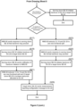
- a first step (S1) of the method of this first embodiment the central unit 10 monitors its connections with each base station in the cellular network 1 to determine a capacity of the connection.
- this includes the central unit 10 monitoring its connection to the second base station 30 and its connection to the third base station 40 to determine their respective capacities.
- the central unit 10 sends a periodic report message to the NMS 60, including data indicating 1) the determined capacity of the central unit's connection with each base station, and 2) the functional split between the central unit 10 and the first distributed unit 20.
- the NMS 60 stores this data in memory.
- the second base station 30 sends a configuration message to the first distributed unit 20 which sets various reporting thresholds for the first distributed unit 20 which, if met, are responded to by the first distributed unit 20 sending a measurement report to the second base station 30.
- the threshold may indicate the Reference Signal Received Power (RSRP) threshold for reference signals from the second base station 30 and, if the RSRP of reference signals from the second base station 30 as measured by the first distributed unit 20 drop below this threshold, then the first distributed unit 20 responds by sending a measurement report to the second base station 30.
- This measurement report identifies other base stations that the first distributed unit 20 receives signals from, and further includes measurements of signals from these other base stations.
- RSRP Reference Signal Received Power
- these reporting thresholds for the first distributed unit 20 are set so that it is more likely that they will be triggered by the first distributed unit 20 (relative to the corresponding reporting thresholds used by UEs of the second base station).
- the threshold for the RSRP of reference signals from the second base station 30 as measured by the first distributed unit 30 may be greater than the threshold for the RSRP of reference signals from the second base station 30 as measured by a UE of the second base station 30, such that it is more likely that this threshold will be met by the first distributed unit 20.
- step S7 the first distributed unit 20 moves into position p 2 (as shown in Figure 4b ) in which a reporting threshold for the first distributed unit 20 to send a measurement report is met.
- the first distributed unit 20 uses a Network Listen (NL) function to identify any base station that it receives signals from.
- position p 2 the first distributed unit 20 is within the coverage area of the third base station 40 and so the first distributed unit 20 identifies and performs one or more measurements of the third base station 40.
- step S9 the first distributed unit 20 compiles and sends a measurement report to the second base station 30.
- the second base station 30 determines which base station should be a donor base station for the first distributed unit 20 based on the measurement report. In this example, the second base station 30 determines that the third base station 40 should be the donor base station, such that the third base station 40 becomes the "target" donor base station.
- step S12 the second base station 30 sets up an inter-base station connection (e.g. an X2 connection) with the third base station 40.
- the second base station 30 requests capacity data from the third base station 40.
- the third base station 30 responds with this capacity data (e.g. information on its current load indicating how many resources are available to support the first distribution unit 20).
- step S13 the second base station 30 sends a request message to the NMS 60 (via the central unit 10), the request message including an identifier for the third base station 40 and data indicating the capacity of the connection between the third base station 40 and the first distributed unit 20.
- the NMS 60 retrieves the latest data indicating the capacity between the central unit 10 and the third base station 40 (from the periodic report message from the central unit 10 in step S3).
- the NMS 60 determines the capacity of an overall connection between the central unit 10 and first distributed unit 20 via the third base station 40, based on both the connection between the central unit 10 and the third base station 40 and the connection between the third base station 40 and the first distributed unit 20.
- step S15 the NMS 60 determines a functional split for the central unit 10 and first distributed unit 20 based on the determined capacity of the overall connection between the central unit 10 and first distributed unit 20 via the third base station 40. In this embodiment, this is based on the following logic:
- the NMS 60 determines that the central unit 10 and first distributed unit 20 should use functional split A. This is because the determined capacity of the overall connection has risen above threshold y, indicating that the connection can accommodate a lower functional split in which more functions are processed in the central unit 10 (such that the central unit 10 may improve coordination of transmissions from several distributed units). As the NMS 60 determines that the functional split is changing from B to A, due to an increase in capacity in the connection via the target donor base station compared to the connection via the source donor base station, the process continues to step S17.
- step S17 the NMS 60 sends a response message to the second base station 30 which indicates that the handover of the first distributed unit 20 to the third base station 40 may continue.
- step S19 the second base station 30 initiates the handover of the first distributed unit 20 to the third base station 40.
- the second base station 30 sends a notification to the NMS 60 that the handover is complete.
- step S21 the NMS 60 sends 1) instruction messages to the central unit 10 and first distributed unit 20 indicating that they should reconfigure to use functional split A (as shown in Figure 4c ), and 2 ) an instruction message to the third base station 40 to increase the amount of resource dedicated to the first distributed unit 20.
- This second instruction message is beneficial as the resources allocated to the third base station's connection with the first distributed unit 20 during the handover only represent the resources required for functional split B but, as this is expected to increase following the change to functional split A, then this second instruction message pre-emptively solves this problem by causing more resources to be allocated to this connection.
- Step S1 to S15 are the same in this embodiment, except the output of the determination in step S15 is that the central unit 10 and first distributed unit 20 should use functional split C (as the determined capacity of the overall connection has dropped below x). The process then continues to step S23.
- step S23 the NMS 60 sends instruction messages to the central unit 10 and first distributed unit 20 indicating that they should reconfigured to use functional split C.
- the central unit 10 and first distributed unit 20 respond by reconfiguring to use functional split C and, following reconfiguration, send a confirmation message to the NMS 60 confirming that the reconfiguration is complete.
- step S25 the NMS 60 receives this confirmation message and sends a response message to the second base station 30 which indicates that the handover of the first distributed unit 20 to the third base station 40 may continue.
- step S27 the second base station initiates the handover of the first distributed unit 20 to the third base station 40.
- the central unit 10 and first distributed unit 20 have already reconfigured to use functional split C, then the connection between these two units via the third base station 40 already accommodates their resource demand. Following these steps, the central unit 10 and first distributed unit 20 are configured as shown in Figure 4d .
- step S29 the third base station 40 sends a configuration message to the distributed unit 20 to set various reporting thresholds.
- These configuration messages are configured so that a handover from a source donor base station having a relatively higher capacity connection to a target donor base station having a relatively lower capacity connection sets a reporting threshold for the first distributed unit 20 that makes it more likely for the first distributed unit 20 to initiate a handover (and vice versa). This encourages the first distributed unit 20 to remain connected to a more suitable serving donor base station.
- the determination of what functional split should be used by the target donor base station may be the same functional split that is currently being used by the source donor base station. In this scenario, the handover may proceed without any change in functional split.
- the first base station is configured to adapt its functional split between its central unit 10 and first distributed unit 20 to implement different proportions of the overall set of functions of the protocol in use (LTE in the above example, although any other cellular/wireless communications protocol may be used).
- LTE Long Term Evolution
- the distributed units may implement the RF functions of the protocol only, and all other functions may be implemented in the central unit.
- these threshold may be dynamic such that the NMS 60 receives feedback on previous functional split reconfigurations indicating whether the reconfiguration was successful or not.
- a successful reconfiguration may be determined as one that does not result in the target base station becoming overloaded immediately or shortly after handover of the distributed unit to the target donor base station.
- the NMS 60 may alter one or more thresholds such that future functional reconfigurations are more likely to be successful.
- the capacity of the connection was determined between the central unit and the first distributed unit via the target donor base station.
- the benefits of the invention may be realised by only using a part of this connection (such as the link between the target donor base station and the first distributed unit).
- the capacity of the connection between the target donor base station and the first distributed unit may be determined by the serving and target donor base stations exchanging messages.
- the first distributed unit may include suitable measurements of the target donor base station in its measurement report which allow the capacity to be determined or estimated. This may include the RSRP of signals between the target donor base station and the first distributed unit, or load information of the target donor base station.
- the reporting thresholds for the first distributed unit are set so that it is more likely that they will be met as compared to those used for UEs of the serving base station.
- the reporting threshold for the first distributed unit may use a relatively higher signal quality (e.g. higher RSRP) to the reporting threshold for the UE. In doing so, there is a greater amount of time between a handover of the first distributed unit to a target base station in order for the functional split change to be effected.
- an NMS makes the determination on whether a functional split change should be made.
- other nodes in the cellular network may implement these steps, including the source donor base station or the central unit.
Landscapes
- Engineering & Computer Science (AREA)
- Computer Networks & Wireless Communication (AREA)
- Signal Processing (AREA)
- Mobile Radio Communication Systems (AREA)
Claims (10)
- Procédé dans un réseau de télécommunications cellulaires (1), le réseau de télécommunications cellulaires (1) comprenant une unité de station de base centrale (10), une première station de base donneuse (30) et une unité de station de base distribuée (20), l'unité de station de base centrale (10) ayant une première interface pour communiquer avec un premier nœud de réseau de cœur cellulaire et une deuxième interface pour communiquer avec la première station de base donneuse (30), la première station de base donneuse (30) ayant une première interface pour communiquer avec l'unité de station de base centrale (10) et une deuxième interface pour communiquer sans fil avec l'unité de station de base distribuée (20), l'unité de station de base distribuée (20) étant mobile et ayant une première interface pour communiquer sans fil avec la première station de base donneuse (30) et une deuxième interface pour communiquer avec un équipement utilisateur, UE, (50), où le trafic utilisateur de l'UE est transmis entre l'unité de station de base centrale (10) et l'UE (50) par l'intermédiaire de la première station de base donneuse (30) et de l'unité de station de base distribuée (20), où il existe une première connexion entre l'unité de station de base centrale (10) et l'unité de station de base distribuée (20) par l'intermédiaire de la première station de base donneuse (30), où l'unité de station de base centrale (10) et l'unité de station de base distribuée (20) mettent en œuvre une première séparation fonctionnelle dans laquelle un premier ensemble de fonctions de protocole est mis en œuvre dans l'unité de station de base distribuée (20) et un deuxième ensemble de fonctions de protocole est mis en œuvre dans l'unité de station de base centrale (10), le procédé comprenant les étapes suivantes :découvrir une deuxième station de base donneuse (40) ayant une première interface pour communiquer avec la première unité de station de base centrale (10) et une deuxième interface pour communiquer sans fil avec l'unité de station de base distribuée (20) ;déterminer une capacité d'une deuxième connexion entre l'unité de station de base centrale (10) et l'unité de station de base distribuée (20) par l'intermédiaire de la deuxième station de base donneuse (40) ;déterminer que la capacité de la deuxième connexion est supérieure ou inférieure à la capacité de la première connexion ; et, en réponse à cette détermination,amener l'unité de station de base centralisée (10) et l'unité de station de base distribuée (20) à mettre en œuvre une deuxième séparation fonctionnelle où un troisième ensemble de fonctions de protocole est mis en œuvre dans l'unité de station de base distribuée (20), le troisième ensemble de fonctions de protocole comprenant moins de fonctions que le premier ensemble de fonctions de protocole si la capacité de la deuxième connexion est supérieure à la capacité de la première connexion ou comprenant plus de fonctions que le premier ensemble de fonctions de protocole si la capacité de la deuxième connexion est inférieure à la capacité de la première connexion, et un quatrième ensemble de fonctions de protocole est mis en œuvre dans l'unité de station de base centrale (10), le quatrième ensemble de fonctions de protocole comprenant plus de fonctions que le deuxième ensemble de fonctions de protocole si la capacité de la deuxième connexion est supérieure à la capacité de la première connexion ou comprenant moins de fonctions que le deuxième ensemble de fonctions de protocole si la capacité de la deuxième connexion est inférieure à la capacité de la première connexion ; etinitier un transfert de l'unité de station de base distribuée (20) de la première station de base donneuse (30) à la deuxième station de base donneuse (40).
- Procédé selon la revendication 1, comprenant en outre les étapes suivantes :
amener la deuxième station de base donneuse (40) à augmenter une proportion de ses ressources globales dédiées à l'unité de station de base distribuée (20). - Procédé selon la revendication 1, dans lequel le transfert est initié et achevé avant que l'unité de station de base centralisée (10) et l'unité de station de base distribuée (20) mettent en œuvre la deuxième séparation fonctionnelle.
- Procédé selon l'une quelconque des revendications précédentes, comprenant en outre les étapes suivantes :
configurer un seuil de signalisation de l'unité de station de base distribuée (20) qui, lorsqu'il est atteint, amène l'unité de station de base distribuée (20) à préparer un rapport de mesure, le seuil étant basé sur la capacité déterminée de la connexion. - Procédé selon l'un quelconque des revendications 1 à 3, comprenant en outre les étapes suivantes :configurer un seuil de signalisation d'un UE de la première station de base donneuse (30) ou de la deuxième station de base donneuse (40) qui, lorsqu'il est satisfait, amène l'UE (50) à préparer un rapport de mesure ; etconfigurer un seuil de signalisation de l'unité de station de base distribuée (20) qui, lorsqu'il est satisfait, amène l'unité de station de base distribuée (20) à préparer un rapport de mesure, où le seuil de signalisation de l'unité de station de base distribuée (20) est basé sur une qualité de signal relativement plus élevée par rapport au seuil de signalisation de l'UE.
- Procédé selon la revendication 5, dans lequel le seuil de signalisation de l'unité de station de base distribuée (20) est en outre basé sur la capacité déterminée de la connexion.
- Procédé selon l'une quelconque des revendications précédentes, dans lequel la capacité de la connexion entre l'unité de station de base centrale (10) et l'unité de station de base distribuée (20) par l'intermédiaire de la deuxième station de base donneuse (40) est déterminée sur la base de la capacité de la connexion entre la deuxième station de base donneuse (40) et l'unité de station de base distribuée (20).
- Produit de programme d'ordinateur comprenant des instructions qui, lorsque le programme est exécuté par un ordinateur, amènent l'ordinateur à exécuter le procédé selon l'une quelconque des revendications précédentes.
- Support de données lisible par ordinateur sur lequel est stocké le programme d'ordinateur de la revendication 8.
- Nœud de réseau pour un réseau de télécommunications cellulaires, le nœud de réseau comprenant un émetteur-récepteur, une mémoire et un processeur adaptés pour coopérer afin de mettre en œuvre les étapes de l'une quelconque des revendications précédentes.
Applications Claiming Priority (2)
| Application Number | Priority Date | Filing Date | Title |
|---|---|---|---|
| EP18190557 | 2018-08-23 | ||
| PCT/EP2019/067971 WO2020038643A1 (fr) | 2018-08-23 | 2019-07-04 | Réseau de télécommunication cellulaire |
Publications (2)
| Publication Number | Publication Date |
|---|---|
| EP3841834A1 EP3841834A1 (fr) | 2021-06-30 |
| EP3841834B1 true EP3841834B1 (fr) | 2025-05-07 |
Family
ID=63556117
Family Applications (1)
| Application Number | Title | Priority Date | Filing Date |
|---|---|---|---|
| EP19736685.9A Active EP3841834B1 (fr) | 2018-08-23 | 2019-07-04 | Réseau de télécommunications cellulaires |
Country Status (7)
| Country | Link |
|---|---|
| US (1) | US11546819B2 (fr) |
| EP (1) | EP3841834B1 (fr) |
| JP (1) | JP7119215B2 (fr) |
| CN (1) | CN112425256B (fr) |
| BR (1) | BR112021003330A2 (fr) |
| ES (1) | ES3034913T3 (fr) |
| WO (1) | WO2020038643A1 (fr) |
Families Citing this family (3)
| Publication number | Priority date | Publication date | Assignee | Title |
|---|---|---|---|---|
| BR112021004878A2 (pt) | 2018-09-21 | 2021-06-01 | British Telecommunications Public Limited Company | rede de telecomunicações celulares |
| WO2024166324A1 (fr) | 2023-02-09 | 2024-08-15 | 本田技研工業株式会社 | Station de base sans fil, dispositif de relais sans fil, corps mobile, système de communication sans fil, procédé de communication sans fil et programme |
| US12556993B2 (en) * | 2023-08-16 | 2026-02-17 | Microsoft Technology Licensing, Llc | Distributed unit architecture for performing handover between distributed units in a VRAN |
Family Cites Families (69)
| Publication number | Priority date | Publication date | Assignee | Title |
|---|---|---|---|---|
| FI88451C (fi) | 1991-07-02 | 1993-05-10 | Telenokia Oy | Foerfarande foer att utfoera positionsdatering fraon ett roerligt cellradiotelefonsystem till ett annat cellradiotelefonsystem |
| GB2317074B (en) | 1996-09-09 | 1998-10-28 | I Co Global Communications | Communications apparatus and method |
| US7400901B2 (en) | 2001-11-19 | 2008-07-15 | At&T Corp. | WLAN having load balancing based on access point loading |
| EP1929713B1 (fr) | 2005-09-16 | 2018-06-13 | Nokia Technologies Oy | Techniques pour fournir des informations de transmission de pilotes de mesures dans des réseaux sans fil |
| EP2082603B1 (fr) | 2006-11-17 | 2018-06-06 | Telefonaktiebolaget LM Ericsson (publ) | Transmission de listes de cellules voisines spéciales |
| CN101686497B (zh) | 2008-09-24 | 2013-04-17 | 华为技术有限公司 | 小区负荷均衡方法、小区负荷评估方法及装置 |
| ES2541291T3 (es) | 2009-03-13 | 2015-07-17 | Nec Corporation | Sistema de comunicación inalámbrica, método, estación de base inalámbrica y estación de control |
| US9432991B2 (en) * | 2009-04-21 | 2016-08-30 | Qualcomm Incorporated | Enabling support for transparent relays in wireless communication |
| CN101909322B (zh) | 2009-06-03 | 2015-05-20 | 中兴通讯股份有限公司 | 一种移动终端及其上报移动状态的方法 |
| GB0917069D0 (en) * | 2009-09-29 | 2009-11-11 | Nokia Siemens Networks Oy | A method and apparatus |
| WO2011066853A1 (fr) * | 2009-12-02 | 2011-06-09 | Nokia Siemens Networks Oy | Transfert de connexions relayées dans un environnement mobile |
| CN102421119A (zh) | 2010-09-28 | 2012-04-18 | 中兴通讯股份有限公司 | 额外测量结果的上报方法及系统 |
| WO2012060608A2 (fr) | 2010-11-01 | 2012-05-10 | 엘지전자 주식회사 | Procédé de coordination de brouillage entre cellules et station de base |
| IL218046B (en) | 2012-02-12 | 2018-11-29 | Elta Systems Ltd | An architecture for a multi-directional relay and the devices and methods of operation useful by the way |
| JP5378629B2 (ja) * | 2011-03-31 | 2013-12-25 | エヌイーシー ヨーロッパ リミテッド | リレー拡張ネットワークにおけるリレーノードの設定および再設定を実行する方法および装置 |
| KR101896001B1 (ko) | 2011-07-12 | 2018-09-06 | 한국전자통신연구원 | 이종 네트워크 환경에서 단말의 이동성 관리 방법 |
| US9883431B2 (en) | 2011-07-22 | 2018-01-30 | Intel Corporation | High speed handovers in a wireless network |
| CN102958174A (zh) | 2011-08-26 | 2013-03-06 | 中兴通讯股份有限公司 | 频谱资源重配方法、装置及系统 |
| US20140220963A1 (en) | 2011-10-02 | 2014-08-07 | Lg Electronics Inc | Method of reporting measurement result in wireless communication system and apparatus for the same |
| KR20130070661A (ko) | 2011-12-14 | 2013-06-28 | 한국전자통신연구원 | 단말간 직접 통신을 위한 제어 방법 |
| CN107135055B (zh) | 2012-01-18 | 2020-06-02 | 华为技术有限公司 | 测量方法,csi-rs资源共享方法和装置 |
| CN109890054B (zh) | 2012-01-21 | 2023-12-15 | 华为技术有限公司 | 无线通信系统中测量增强的方法和装置 |
| CN104067667A (zh) | 2012-01-23 | 2014-09-24 | 英特尔公司 | 用于集成的多rat异类网络的网络辅助的用户关联和卸载技术 |
| EP2818002A4 (fr) | 2012-02-24 | 2015-10-28 | Intel Corp | Réseau d'accès radio coopératif avec groupe de traitement d'unité de bande de base (bbu) de station de base centralisé |
| JP5851914B2 (ja) | 2012-03-30 | 2016-02-03 | 富士通株式会社 | 移動局位置検出方法、移動通信システム、および移動局位置情報管理装置 |
| PT2850902T (pt) | 2012-05-16 | 2017-03-02 | ERICSSON TELEFON AB L M (publ) | Método e configuração numa rede de comunicações |
| US9622123B2 (en) | 2012-06-11 | 2017-04-11 | Telefonaktiebolaget Lm Ericsson (Publ) | Methods for handover configuration |
| KR101708574B1 (ko) | 2012-08-23 | 2017-02-20 | 인터디지탈 패튼 홀딩스, 인크 | 무선 시스템에서의 다중 스케줄러들을 이용한 동작 |
| US8761142B2 (en) | 2012-10-19 | 2014-06-24 | Ubiquiti Networks, Inc. | Distributed seamless roaming in wireless networks |
| CN106211340A (zh) | 2012-12-14 | 2016-12-07 | 华为技术有限公司 | 子母基站簇、集中单元、拉远单元及信息处理方法 |
| EP2753142B1 (fr) | 2013-01-08 | 2015-08-19 | Alcatel Lucent | Appareil, procédé et programme informatique de traitement de données de bande de base de division entre une pluralité d'unités de traitement de bande de base |
| WO2014133589A1 (fr) | 2013-03-01 | 2014-09-04 | Intel Corporation | Décharge de trafic de réseau local sans-fil (wlan) |
| US20160044518A1 (en) | 2013-04-05 | 2016-02-11 | Telefonaktiebolaget L M Ericsson (Publ) | Methods of operating radio access network base stations and related network nodes |
| CN105519167B (zh) | 2013-07-04 | 2020-01-14 | 韩国电子通信研究院 | 移动通信系统中用于支持多连接的控制方法和用于支持多连接的设备 |
| KR102083322B1 (ko) | 2013-08-22 | 2020-03-03 | 삼성전자주식회사 | 이동 통신 시스템에서 고립 사용자 단말기에 대한 디바이스-투-디바이스 통신 기반 서비스 제공 장치 및 방법 |
| ES2458621B1 (es) | 2013-10-15 | 2015-02-10 | Aoife Solutions, S.L. | Sistema de control descentralizado de redes inalámbricas |
| JP6433657B2 (ja) * | 2013-12-18 | 2018-12-05 | 株式会社Nttドコモ | 無線基地局、移動局、及び無線通信方法 |
| CN103813347B (zh) | 2014-02-28 | 2018-01-26 | 电信科学技术研究院 | 一种基站频率资源配置方法及网络设备 |
| EP3195644B1 (fr) | 2014-09-17 | 2018-04-18 | Telefonaktiebolaget LM Ericsson (publ) | Système de virtualisation |
| US10292058B2 (en) | 2014-12-16 | 2019-05-14 | New Jersey Institute Of Technology | Radio over fiber antenna extender systems and methods for high speed trains |
| CN106332129B (zh) | 2015-06-30 | 2020-03-31 | 华为技术有限公司 | 无线网络功能的配置方法、无线网络节点及核心网设备 |
| US11356986B2 (en) | 2015-10-15 | 2022-06-07 | Telefonaktiebolaget Lm Ericsson (Publ) | Methods, apparatuses and computer programs for providing an X2 interface between a network unit and a remote network in wireless communication systems |
| JP6423107B2 (ja) | 2015-11-05 | 2018-11-14 | 京セラ株式会社 | 基地局、プロセッサ、及び終端装置 |
| CN109804569B (zh) | 2016-05-11 | 2021-12-07 | 索尼公司 | 无线系统中的分布式控制 |
| KR102100491B1 (ko) | 2016-07-13 | 2020-04-14 | 주식회사 케이티 | 프론트홀 인터페이스를 이용한 중앙 유닛 구성 방법 및 그 장치 |
| CN107734568A (zh) | 2016-08-11 | 2018-02-23 | 北京三星通信技术研究有限公司 | 在无线通信中支持用户设备移动的方法、装置及设备 |
| GB2552844A (en) | 2016-08-12 | 2018-02-14 | Nec Corp | Communication system |
| US10298313B2 (en) * | 2016-09-13 | 2019-05-21 | Sprint Spectrum L.P. | Systems and methods for selecting a donor for a relay wireless device |
| WO2018063998A1 (fr) * | 2016-09-30 | 2018-04-05 | Intel Corporation | Systèmes, procédés et dispositifs pour interface divisée mac-phy |
| US11019547B1 (en) * | 2016-10-06 | 2021-05-25 | Sprint Spectrum L.P. | Controlling handover parameters based on target base station characteristics |
| US11696218B2 (en) * | 2016-10-21 | 2023-07-04 | Qualcomm Incorporated | Multiplexing initial access and data transmissions in assisted millimeter wave systems |
| WO2018089803A1 (fr) | 2016-11-14 | 2018-05-17 | Intel IP Corporation | Réinitialisation de pile de protocoles dynamique lors d'un transfert radio |
| KR102746233B1 (ko) * | 2017-02-10 | 2024-12-26 | 한국전자통신연구원 | 통신 네트워크에서 통신 노드의 동작 방법 |
| US20180241452A1 (en) * | 2017-02-23 | 2018-08-23 | Qualcomm Incorporated | Beam sweeping for control and data transmissions |
| JP6654590B2 (ja) | 2017-02-28 | 2020-02-26 | 日本電信電話株式会社 | アクセスポイント管理システム、アクセスポイント管理方法、及びアクセスポイント管理装置 |
| US10264622B2 (en) | 2017-03-17 | 2019-04-16 | Ofinno Technologies, Llc | Inactive state data forwarding |
| US10644974B2 (en) | 2017-05-04 | 2020-05-05 | At&T Intellectual Property I, L.P. | Measurements and radio link monitoring in a wireless communications system |
| US10469358B2 (en) | 2017-05-18 | 2019-11-05 | Qualcomm Incorporated | Wireless multihop relay |
| US10680700B2 (en) * | 2017-07-24 | 2020-06-09 | Qualcomm Incorporated | Parameter adjustment for radio link failure (RLF) procedure enhanced by aperiodic beam failure recovery (BFR) triggers |
| US10750453B2 (en) * | 2017-09-07 | 2020-08-18 | Ofinno, Llc | Sounding reference signal transmission for uplink beam management |
| US10660063B2 (en) * | 2017-11-16 | 2020-05-19 | Comcast Cable Communications, Llc | Beam paging assistance |
| US10980051B2 (en) | 2018-01-22 | 2021-04-13 | Qualcomm Incorporated | Physical downlink control channel (PDCCH) repetition and decoding for ultra-reliability low latency communication (URLLC) |
| US20190289478A1 (en) | 2018-03-19 | 2019-09-19 | Qualcomm Incorporated | Physical downlink control channel (pdcch) reliability for ultra-reliability low latency communication (urllc) |
| US11394520B2 (en) | 2018-03-23 | 2022-07-19 | Qualcomm Incorporated | Considerations on bandwidth part (BWP) management for ultra-reliability low latency communication (URLLC) |
| US11303419B2 (en) | 2018-04-06 | 2022-04-12 | Qualcomm Incorporated | Semi-static HARQ-ACK codebook with multiple PDSCH transmissions per slot |
| US11483747B2 (en) * | 2018-04-23 | 2022-10-25 | Beijing Xiaomi Mobile Software Co., Ltd. | Methods of restoring wireless backhaul link and establishing wireless backhaul link, NR wireless backhaul base station, and NR donor base station |
| WO2019246446A1 (fr) * | 2018-06-21 | 2019-12-26 | Google Llc | Maintien d'interfaces de communication et de signalisation par l'intermédiaire d'un transfert intercellulaire de station de base donneuse |
| US11184869B2 (en) * | 2018-06-26 | 2021-11-23 | Qualcomm Incorporated | Timing alignment timer in a wireless communication network |
| BR112021004878A2 (pt) | 2018-09-21 | 2021-06-01 | British Telecommunications Public Limited Company | rede de telecomunicações celulares |
-
2019
- 2019-07-04 WO PCT/EP2019/067971 patent/WO2020038643A1/fr not_active Ceased
- 2019-07-04 EP EP19736685.9A patent/EP3841834B1/fr active Active
- 2019-07-04 CN CN201980047009.9A patent/CN112425256B/zh active Active
- 2019-07-04 BR BR112021003330-0A patent/BR112021003330A2/pt unknown
- 2019-07-04 ES ES19736685T patent/ES3034913T3/es active Active
- 2019-07-04 JP JP2021510035A patent/JP7119215B2/ja active Active
- 2019-07-04 US US17/250,696 patent/US11546819B2/en active Active
Also Published As
| Publication number | Publication date |
|---|---|
| EP3841834A1 (fr) | 2021-06-30 |
| US11546819B2 (en) | 2023-01-03 |
| CN112425256A (zh) | 2021-02-26 |
| WO2020038643A1 (fr) | 2020-02-27 |
| BR112021003330A2 (pt) | 2021-05-11 |
| CN112425256B (zh) | 2024-01-05 |
| ES3034913T3 (en) | 2025-08-26 |
| JP2021536175A (ja) | 2021-12-23 |
| JP7119215B2 (ja) | 2022-08-16 |
| US20210204185A1 (en) | 2021-07-01 |
Similar Documents
| Publication | Publication Date | Title |
|---|---|---|
| US11729700B2 (en) | Communication related to network slice information | |
| US11134427B2 (en) | Terminal, base station, cell access method, and data transmission method for reconfiguring a wireless connection to communicate with a secondary cell | |
| WO2021097801A1 (fr) | Procédés et appareil de routage de paquet pour un relais de liaison latérale | |
| JP7742506B2 (ja) | ランダムアクセスチャネルレス層1/層2トリガモビリティの実現 | |
| CN115280898A (zh) | Ue到网络中继的基于路径切换的服务连续性的方法和设备 | |
| US20190222291A1 (en) | Method and apparatus for supporting movement of user equipment in wireless communications | |
| CN104581854B (zh) | 一种无线连接方法和装置 | |
| KR20200080307A (ko) | 타깃 plmn id 및 타깃 셀 id를 결정하는 노드들 및 방법 | |
| US12464420B2 (en) | Communication method and communication apparatus | |
| CN104468029A (zh) | 一种移动终端通信方法、装置及相关设备 | |
| WO2021168647A1 (fr) | Procédé de fourniture de tranche de réseau, et appareil de communication | |
| JP6658901B2 (ja) | 通信装置、通信システム、方法及びプログラム | |
| US10412665B2 (en) | AP group information processing method and eNB | |
| US20160192283A1 (en) | Method for searching wireless lan and method for transferring wireless lan search information | |
| US11546819B2 (en) | Cellular telecommunications network | |
| WO2021097678A1 (fr) | Procédé et appareil de commande d'accès et de liaison terrestre | |
| US9344928B2 (en) | Neighbouring cell optimization method and mobile communication system | |
| CN114071602B (zh) | 一种节点切换配置方法及装置 | |
| KR20120016572A (ko) | 무선 네트워크에서의 디바이스, 디바이스 자원 관리 장치, 게이트웨이, 및 네트워크 서버, 및 네트워크 서버의 제어 방법 | |
| GB2576554A (en) | Cellular telecommunications network | |
| US20240430714A1 (en) | Reducing small cell downtime during intermittent failures | |
| US20240334265A1 (en) | Methods, apparatuses and systems for pscell measurement activation during nr-dc | |
| WO2026068420A1 (fr) | Gestion de tampon de station pour itinérance | |
| WO2024027993A1 (fr) | Améliorations apportées à la gestion de faisceau | |
| CN121013135A (zh) | 小区切换方法、装置、设备、介质及程序产品 |
Legal Events
| Date | Code | Title | Description |
|---|---|---|---|
| STAA | Information on the status of an ep patent application or granted ep patent |
Free format text: STATUS: UNKNOWN |
|
| STAA | Information on the status of an ep patent application or granted ep patent |
Free format text: STATUS: THE INTERNATIONAL PUBLICATION HAS BEEN MADE |
|
| PUAI | Public reference made under article 153(3) epc to a published international application that has entered the european phase |
Free format text: ORIGINAL CODE: 0009012 |
|
| STAA | Information on the status of an ep patent application or granted ep patent |
Free format text: STATUS: REQUEST FOR EXAMINATION WAS MADE |
|
| 17P | Request for examination filed |
Effective date: 20201211 |
|
| AK | Designated contracting states |
Kind code of ref document: A1 Designated state(s): AL AT BE BG CH CY CZ DE DK EE ES FI FR GB GR HR HU IE IS IT LI LT LU LV MC MK MT NL NO PL PT RO RS SE SI SK SM TR |
|
| DAV | Request for validation of the european patent (deleted) | ||
| DAX | Request for extension of the european patent (deleted) | ||
| RAP3 | Party data changed (applicant data changed or rights of an application transferred) |
Owner name: BRITISH TELECOMMUNICATIONS PUBLIC LIMITED COMPANY |
|
| STAA | Information on the status of an ep patent application or granted ep patent |
Free format text: STATUS: EXAMINATION IS IN PROGRESS |
|
| 17Q | First examination report despatched |
Effective date: 20230216 |
|
| P01 | Opt-out of the competence of the unified patent court (upc) registered |
Effective date: 20230623 |
|
| REG | Reference to a national code |
Ref country code: DE Ref legal event code: R079 Free format text: PREVIOUS MAIN CLASS: H04W0084000000 Ipc: H04W0036080000 Ref document number: 602019069626 Country of ref document: DE |
|
| GRAP | Despatch of communication of intention to grant a patent |
Free format text: ORIGINAL CODE: EPIDOSNIGR1 |
|
| STAA | Information on the status of an ep patent application or granted ep patent |
Free format text: STATUS: GRANT OF PATENT IS INTENDED |
|
| RIC1 | Information provided on ipc code assigned before grant |
Ipc: H04W 36/32 20090101ALN20241128BHEP Ipc: H04W 88/08 20090101ALI20241128BHEP Ipc: H04W 84/00 20090101ALI20241128BHEP Ipc: H04W 36/30 20090101ALI20241128BHEP Ipc: H04W 36/08 20090101AFI20241128BHEP |
|
| INTG | Intention to grant announced |
Effective date: 20241205 |
|
| GRAS | Grant fee paid |
Free format text: ORIGINAL CODE: EPIDOSNIGR3 |
|
| GRAA | (expected) grant |
Free format text: ORIGINAL CODE: 0009210 |
|
| STAA | Information on the status of an ep patent application or granted ep patent |
Free format text: STATUS: THE PATENT HAS BEEN GRANTED |
|
| AK | Designated contracting states |
Kind code of ref document: B1 Designated state(s): AL AT BE BG CH CY CZ DE DK EE ES FI FR GB GR HR HU IE IS IT LI LT LU LV MC MK MT NL NO PL PT RO RS SE SI SK SM TR |
|
| REG | Reference to a national code |
Ref country code: GB Ref legal event code: FG4D |
|
| REG | Reference to a national code |
Ref country code: CH Ref legal event code: EP |
|
| REG | Reference to a national code |
Ref country code: DE Ref legal event code: R096 Ref document number: 602019069626 Country of ref document: DE |
|
| REG | Reference to a national code |
Ref country code: IE Ref legal event code: FG4D |
|
| PGFP | Annual fee paid to national office [announced via postgrant information from national office to epo] |
Ref country code: FR Payment date: 20250620 Year of fee payment: 7 |
|
| REG | Reference to a national code |
Ref country code: ES Ref legal event code: FG2A Ref document number: 3034913 Country of ref document: ES Kind code of ref document: T3 Effective date: 20250826 |
|
| REG | Reference to a national code |
Ref country code: NL Ref legal event code: MP Effective date: 20250507 |
|
| PG25 | Lapsed in a contracting state [announced via postgrant information from national office to epo] |
Ref country code: PT Free format text: LAPSE BECAUSE OF FAILURE TO SUBMIT A TRANSLATION OF THE DESCRIPTION OR TO PAY THE FEE WITHIN THE PRESCRIBED TIME-LIMIT Effective date: 20250908 Ref country code: FI Free format text: LAPSE BECAUSE OF FAILURE TO SUBMIT A TRANSLATION OF THE DESCRIPTION OR TO PAY THE FEE WITHIN THE PRESCRIBED TIME-LIMIT Effective date: 20250507 |
|
| PGFP | Annual fee paid to national office [announced via postgrant information from national office to epo] |
Ref country code: ES Payment date: 20250801 Year of fee payment: 7 |
|
| PGFP | Annual fee paid to national office [announced via postgrant information from national office to epo] |
Ref country code: DE Payment date: 20250620 Year of fee payment: 7 |
|
| REG | Reference to a national code |
Ref country code: LT Ref legal event code: MG9D |
|
| PG25 | Lapsed in a contracting state [announced via postgrant information from national office to epo] |
Ref country code: NO Free format text: LAPSE BECAUSE OF FAILURE TO SUBMIT A TRANSLATION OF THE DESCRIPTION OR TO PAY THE FEE WITHIN THE PRESCRIBED TIME-LIMIT Effective date: 20250807 Ref country code: GR Free format text: LAPSE BECAUSE OF FAILURE TO SUBMIT A TRANSLATION OF THE DESCRIPTION OR TO PAY THE FEE WITHIN THE PRESCRIBED TIME-LIMIT Effective date: 20250808 |
|
| PG25 | Lapsed in a contracting state [announced via postgrant information from national office to epo] |
Ref country code: PL Free format text: LAPSE BECAUSE OF FAILURE TO SUBMIT A TRANSLATION OF THE DESCRIPTION OR TO PAY THE FEE WITHIN THE PRESCRIBED TIME-LIMIT Effective date: 20250507 Ref country code: NL Free format text: LAPSE BECAUSE OF FAILURE TO SUBMIT A TRANSLATION OF THE DESCRIPTION OR TO PAY THE FEE WITHIN THE PRESCRIBED TIME-LIMIT Effective date: 20250507 |
|
| REG | Reference to a national code |
Ref country code: AT Ref legal event code: MK05 Ref document number: 1793870 Country of ref document: AT Kind code of ref document: T Effective date: 20250507 |
|
| PG25 | Lapsed in a contracting state [announced via postgrant information from national office to epo] |
Ref country code: BG Free format text: LAPSE BECAUSE OF FAILURE TO SUBMIT A TRANSLATION OF THE DESCRIPTION OR TO PAY THE FEE WITHIN THE PRESCRIBED TIME-LIMIT Effective date: 20250507 |
|
| PG25 | Lapsed in a contracting state [announced via postgrant information from national office to epo] |
Ref country code: HR Free format text: LAPSE BECAUSE OF FAILURE TO SUBMIT A TRANSLATION OF THE DESCRIPTION OR TO PAY THE FEE WITHIN THE PRESCRIBED TIME-LIMIT Effective date: 20250507 |
|
| PG25 | Lapsed in a contracting state [announced via postgrant information from national office to epo] |
Ref country code: AT Free format text: LAPSE BECAUSE OF FAILURE TO SUBMIT A TRANSLATION OF THE DESCRIPTION OR TO PAY THE FEE WITHIN THE PRESCRIBED TIME-LIMIT Effective date: 20250507 |
|
| PG25 | Lapsed in a contracting state [announced via postgrant information from national office to epo] |
Ref country code: RS Free format text: LAPSE BECAUSE OF FAILURE TO SUBMIT A TRANSLATION OF THE DESCRIPTION OR TO PAY THE FEE WITHIN THE PRESCRIBED TIME-LIMIT Effective date: 20250807 |
|
| PG25 | Lapsed in a contracting state [announced via postgrant information from national office to epo] |
Ref country code: IS Free format text: LAPSE BECAUSE OF FAILURE TO SUBMIT A TRANSLATION OF THE DESCRIPTION OR TO PAY THE FEE WITHIN THE PRESCRIBED TIME-LIMIT Effective date: 20250907 |
|
| PG25 | Lapsed in a contracting state [announced via postgrant information from national office to epo] |
Ref country code: LV Free format text: LAPSE BECAUSE OF FAILURE TO SUBMIT A TRANSLATION OF THE DESCRIPTION OR TO PAY THE FEE WITHIN THE PRESCRIBED TIME-LIMIT Effective date: 20250507 |
|
| PG25 | Lapsed in a contracting state [announced via postgrant information from national office to epo] |
Ref country code: DK Free format text: LAPSE BECAUSE OF FAILURE TO SUBMIT A TRANSLATION OF THE DESCRIPTION OR TO PAY THE FEE WITHIN THE PRESCRIBED TIME-LIMIT Effective date: 20250507 Ref country code: SM Free format text: LAPSE BECAUSE OF FAILURE TO SUBMIT A TRANSLATION OF THE DESCRIPTION OR TO PAY THE FEE WITHIN THE PRESCRIBED TIME-LIMIT Effective date: 20250507 |
|
| PG25 | Lapsed in a contracting state [announced via postgrant information from national office to epo] |
Ref country code: CZ Free format text: LAPSE BECAUSE OF FAILURE TO SUBMIT A TRANSLATION OF THE DESCRIPTION OR TO PAY THE FEE WITHIN THE PRESCRIBED TIME-LIMIT Effective date: 20250507 |
|
| PG25 | Lapsed in a contracting state [announced via postgrant information from national office to epo] |
Ref country code: EE Free format text: LAPSE BECAUSE OF FAILURE TO SUBMIT A TRANSLATION OF THE DESCRIPTION OR TO PAY THE FEE WITHIN THE PRESCRIBED TIME-LIMIT Effective date: 20250507 |
|
| PG25 | Lapsed in a contracting state [announced via postgrant information from national office to epo] |
Ref country code: SK Free format text: LAPSE BECAUSE OF FAILURE TO SUBMIT A TRANSLATION OF THE DESCRIPTION OR TO PAY THE FEE WITHIN THE PRESCRIBED TIME-LIMIT Effective date: 20250507 Ref country code: RO Free format text: LAPSE BECAUSE OF FAILURE TO SUBMIT A TRANSLATION OF THE DESCRIPTION OR TO PAY THE FEE WITHIN THE PRESCRIBED TIME-LIMIT Effective date: 20250507 |
|
| PG25 | Lapsed in a contracting state [announced via postgrant information from national office to epo] |
Ref country code: IT Free format text: LAPSE BECAUSE OF FAILURE TO SUBMIT A TRANSLATION OF THE DESCRIPTION OR TO PAY THE FEE WITHIN THE PRESCRIBED TIME-LIMIT Effective date: 20250507 |
|
| REG | Reference to a national code |
Ref country code: DE Ref legal event code: R097 Ref document number: 602019069626 Country of ref document: DE |
|
| REG | Reference to a national code |
Ref country code: CH Ref legal event code: H13 Free format text: ST27 STATUS EVENT CODE: U-0-0-H10-H13 (AS PROVIDED BY THE NATIONAL OFFICE) Effective date: 20260224 |
|
| PLBE | No opposition filed within time limit |
Free format text: ORIGINAL CODE: 0009261 |
|
| STAA | Information on the status of an ep patent application or granted ep patent |
Free format text: STATUS: NO OPPOSITION FILED WITHIN TIME LIMIT |
|
| PG25 | Lapsed in a contracting state [announced via postgrant information from national office to epo] |
Ref country code: LU Free format text: LAPSE BECAUSE OF NON-PAYMENT OF DUE FEES Effective date: 20250704 |
|
| REG | Reference to a national code |
Ref country code: CH Ref legal event code: L10 Free format text: ST27 STATUS EVENT CODE: U-0-0-L10-L00 (AS PROVIDED BY THE NATIONAL OFFICE) Effective date: 20260318 |
|
| REG | Reference to a national code |
Ref country code: BE Ref legal event code: MM Effective date: 20250731 |
|
| 26N | No opposition filed |
Effective date: 20260210 |
|
| PG25 | Lapsed in a contracting state [announced via postgrant information from national office to epo] |
Ref country code: BE Free format text: LAPSE BECAUSE OF NON-PAYMENT OF DUE FEES Effective date: 20250731 |
|
| PG25 | Lapsed in a contracting state [announced via postgrant information from national office to epo] |
Ref country code: CH Free format text: LAPSE BECAUSE OF NON-PAYMENT OF DUE FEES Effective date: 20250731 |
|
| GBPC | Gb: european patent ceased through non-payment of renewal fee |
Effective date: 20250807 |