EP3841912B1 - Dispositif pour réduire le matériau excédentaire sur les produits de monnaie - Google Patents
Dispositif pour réduire le matériau excédentaire sur les produits de monnaie Download PDFInfo
- Publication number
- EP3841912B1 EP3841912B1 EP21153752.7A EP21153752A EP3841912B1 EP 3841912 B1 EP3841912 B1 EP 3841912B1 EP 21153752 A EP21153752 A EP 21153752A EP 3841912 B1 EP3841912 B1 EP 3841912B1
- Authority
- EP
- European Patent Office
- Prior art keywords
- mint
- processed
- product
- products
- giveaway material
- Prior art date
- Legal status (The legal status is an assumption and is not a legal conclusion. Google has not performed a legal analysis and makes no representation as to the accuracy of the status listed.)
- Active
Links
Images


Classifications
-
- B—PERFORMING OPERATIONS; TRANSPORTING
- B26—HAND CUTTING TOOLS; CUTTING; SEVERING
- B26D—CUTTING; DETAILS COMMON TO MACHINES FOR PERFORATING, PUNCHING, CUTTING-OUT, STAMPING-OUT OR SEVERING
- B26D5/00—Arrangements for operating and controlling machines or devices for cutting, cutting-out, stamping-out, punching, perforating, or severing by means other than cutting
-
- B—PERFORMING OPERATIONS; TRANSPORTING
- B26—HAND CUTTING TOOLS; CUTTING; SEVERING
- B26D—CUTTING; DETAILS COMMON TO MACHINES FOR PERFORATING, PUNCHING, CUTTING-OUT, STAMPING-OUT OR SEVERING
- B26D7/00—Details of apparatus for cutting, cutting-out, stamping-out, punching, perforating, or severing by means other than cutting
- B26D7/01—Means for holding or positioning work
-
- B—PERFORMING OPERATIONS; TRANSPORTING
- B44—DECORATIVE ARTS
- B44B—MACHINES, APPARATUS OR TOOLS FOR ARTISTIC WORK, e.g. FOR SCULPTURING, GUILLOCHING, CARVING, BRANDING, INLAYING
- B44B5/00—Machines or apparatus for embossing decorations or marks, e.g. embossing coins
-
- B—PERFORMING OPERATIONS; TRANSPORTING
- B44—DECORATIVE ARTS
- B44B—MACHINES, APPARATUS OR TOOLS FOR ARTISTIC WORK, e.g. FOR SCULPTURING, GUILLOCHING, CARVING, BRANDING, INLAYING
- B44B5/00—Machines or apparatus for embossing decorations or marks, e.g. embossing coins
- B44B5/02—Dies; Accessories
- B44B5/024—Work piece loading or discharging arrangements
-
- G—PHYSICS
- G01—MEASURING; TESTING
- G01G—WEIGHING
- G01G19/00—Weighing apparatus or methods adapted for special purposes not provided for in the preceding groups
-
- A—HUMAN NECESSITIES
- A44—HABERDASHERY; JEWELLERY
- A44C—PERSONAL ADORNMENTS, e.g. JEWELLERY; COINS
- A44C21/00—Coins; Emergency money; Beer or gambling coins or tokens, or the like
-
- A—HUMAN NECESSITIES
- A44—HABERDASHERY; JEWELLERY
- A44C—PERSONAL ADORNMENTS, e.g. JEWELLERY; COINS
- A44C27/00—Making jewellery or other personal adornments
-
- G—PHYSICS
- G01—MEASURING; TESTING
- G01G—WEIGHING
- G01G19/00—Weighing apparatus or methods adapted for special purposes not provided for in the preceding groups
- G01G19/40—Weighing apparatus or methods adapted for special purposes not provided for in the preceding groups with provisions for indicating, recording, or computing price or other quantities dependent on the weight
- G01G19/413—Weighing apparatus or methods adapted for special purposes not provided for in the preceding groups with provisions for indicating, recording, or computing price or other quantities dependent on the weight using electromechanical or electronic computing means
- G01G19/414—Weighing apparatus or methods adapted for special purposes not provided for in the preceding groups with provisions for indicating, recording, or computing price or other quantities dependent on the weight using electromechanical or electronic computing means using electronic computing means only
-
- Y—GENERAL TAGGING OF NEW TECHNOLOGICAL DEVELOPMENTS; GENERAL TAGGING OF CROSS-SECTIONAL TECHNOLOGIES SPANNING OVER SEVERAL SECTIONS OF THE IPC; TECHNICAL SUBJECTS COVERED BY FORMER USPC CROSS-REFERENCE ART COLLECTIONS [XRACs] AND DIGESTS
- Y10—TECHNICAL SUBJECTS COVERED BY FORMER USPC
- Y10T—TECHNICAL SUBJECTS COVERED BY FORMER US CLASSIFICATION
- Y10T29/00—Metal working
- Y10T29/49—Method of mechanical manufacture
- Y10T29/49995—Shaping one-piece blank by removing material
Definitions
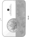
- the present invention relates to a machine for reducing giveaway material on products. More particularly, and according to a preferred embodiment, the present invention relates to a machine for reducing giveaway material on mint products, such as bullion products, investment products, numismatic products, circulation products, medals, medallions, ingots, bars, blanks, cast bars, minted bars, minted coins, and the like.
- mint products such as bullion products, investment products, numismatic products, circulation products, medals, medallions, ingots, bars, blanks, cast bars, minted bars, minted coins, and the like.
- the troy ounce (ozt) is a unit of imperial measure. In the present day, it is most commonly used to gauge the weight and therefore the price of precious metals. One troy ounce is equivalent to 31.1034768 grams. Accordingly, the minimum net weight of a 1-oz bullion product must reflect the purity of the material. For example:
- a mint is an industrial facility which manufactures coins for currency, and other related products.
- the object of the present invention is to provide a machine which satisfies some of the above-mentioned needs and which is thus an improvement over the prior art.
- Another object of the present invention is to reduce and recover, as much as possible, the amount of giveaway material on a given product, particularly on a product made of or containing precious metal, in a substantially precise, systematic and repeatable manner.
- Another object of the present invention is to remove and recover giveaway material from products made of substantially solid precious metals.
- Another object of the present invention is to remove and recover giveaway material from mint products, by processing said mint products in a very precise, systematic and repeatable manner, at a convenient location during a manufacturing process, so as to ensure that removal of giveaway material on the resulting products of said processed mint products is practically unnoticeable, or at the very least, satisfies a given criteria of visual quality assurance.
- the present invention is particularly advantageous in that it can be easily incorporated into a standard manufacturing process for producing mint products made of solid precious metals (such as gold, silver, platinum and palladium, for example), and in that it enables to improve the accuracy of these products by reducing the weight of the products closer to the minimum allowed weight of legal trade, thereby reducing the amount of giveaway material being "given away", which can represent millions and millions of dollars in savings per year.
- solid precious metals such as gold, silver, platinum and palladium, for example
- the present invention was primarily designed to remove (i.e. "recover") giveaway material on "mint” products, such as bullion investment products, for example, it may be used with other types of objects, and in other fields, as apparent to a person skilled in the art.
- “mint”, “giveaway”, “bullion”, “investment”, “product”, etc., used herein should not be taken as to limit the scope of the present invention and includes all other kinds of objects or fields with which the present invention could be used and may be useful (ex. coins or tokens used for recreational purposes and the like), as apparent to a person skilled in the art.
- a precious metal such as gold, silver, platinum and palladium, for example.
- the present invention is advantageous in that it enables to improve the accuracy of these products (107) by reducing the weight of the products (107) closer to the minimum allowed weight of legal trade, or to a given threshold, thereby avoiding that excess extra material of high value from being simply given away.
- the processing assembly (111) of the machine (103) is configured for: a) evaluating at least one physical parameter of a given mint product (107) to be processed; b) comparing said at least one physical parameter of the mint product (107) to be processed with a minimum threshold physical parameter in order to determine an attainable range of giveaway material to be removed; c) projecting or calculating a targeted amount of giveaway material to be removed from the mint product (107) to be processed depending on, or as a function of, the attainable range of giveaway material; and d) removing the targeted amount of giveaway material via at least one surface (115) (portion, etc.) of the mint product (107).
- the processing assembly (111) preferably comprises an evaluating assembly (117) for evaluating at least one physical parameter of the mint product (107) to be processed.
- the at least one physical parameter of the mint product (107) to be processed is weight, to be used to determine an amount of giveaway material to be removed (or any other consideration for that matter), or the best mode in which to do so, as can be easily understood by a person skilled in the art
- the processing assembly (111) comprises a weighing assembly (119) for weighing the mint product (107) to be processed.
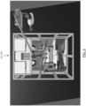
- the weighing assembly (119) comprises at least one scale (121) operatively resting on a ground surface (123) via at least one vibration-dampening assembly (125), and according to a preferred embodiment of the present invention, each scale (121) is operatively isolated from the rest of the machine (102), so as to have precise readings (ex. a tolerance of about +/- 2 mg).
- the weighing assembly (119) comprises an adjustment mechanism (127) for adjusting a value of the weight being measured for a given mint product (107) to be processed depending on previous readings and other previous mint products (107) having been processed, so that the present system (101) can "learn” and “adjust” itself accordingly for achieving even more precise results.
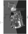
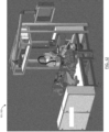
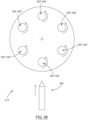
- the processing assembly (111) preferably comprises at least one rotating carrousel (129) having pockets (131) for receiving a plurality of mint products (107) to be processed, and also comprises a manipulating assembly (133) for manipulating the mints products (107) to be processed.
- the manipulating assembly (133) comprises at least one articulated arm (135), and preferably a pair of such articulated arms (135a,135b), and each articulated arm (135) is configured for manipulating a given mint product (107) to be processed to and from a corresponding carrousel (129).
- the manipulating assembly (133) comprises a centering assembly (137) for centering each mint product (107) to be processed with respect a corresponding reference line or point.
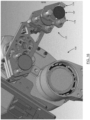
- the processing assembly (111) comprises first and second clamping components (143a,143b) (i.e. clampers) for clamping each mint product (107) to be processed, the clamping components (143) being preferably made of high polished steel.
- the processing assembly (111) is preferably configured for rotating each mint product (107) to be processed with respect to a corresponding reference line (139) or point (141), and the processing assembly (111) is preferably configured for vertical displacing each mint product (107) to be processed with respect to a corresponding reference line (139) or point (141).
- the processing assembly (111) comprises a scanning assembly (145) for scanning the mint product (107) to be processed, and for generating a corresponding profile thereof. This visual information obtained by the scanning assembly (145) can then be advantageously used for calculating an exact amount of targeted giveaway material to be removed.
- the processing assembly (111) further comprises a material-removal assembly (147) for removing giveaway material from the mint product (107) to be processed, which, in its simplest form, may consist of a cutting assembly (149) for cutting away giveaway material from the mint product (107) to be processed, using a cutting tool (151), such as a carbide cutting tool (151) having a given radius of curvature (153), as will be explained in greater detail hereinbelow.
- a material-removal assembly (147) for removing giveaway material from the mint product (107) to be processed which, in its simplest form, may consist of a cutting assembly (149) for cutting away giveaway material from the mint product (107) to be processed, using a cutting tool (151), such as a carbide cutting tool (151) having a given radius of curvature (153), as will be explained in greater detail hereinbelow.
- the processing assembly (111) comprises a computing assembly (155) for receiving and computing data associated with the mints products (107), and for adjusting parameters of the machine (103) according to said data.
- the mint products to be processed such as for example, in our illustrative case, products (107) or blanks for 1-oz silver round coins, are inserted into a blank bunker (157) acting as a feeding hopper.
- the blank bunker (157) is preferably configured so as to avoid jamming of the blanks within the bunker, and so that the blanks fall by gravity, down to a portion of the system (101) where the blanks are fed to an upstream conveyor (159).
- the upstream conveyor (159) brings the blanks to a blank drum (161) which is preferably configured to rotate, and is also provided with pockets (163), so that blanks inserted into said pockets (163) are then individually fed via a rotation of the blank drum (161) into a corresponding chute (165) for aligning singled blanks.
- each blank is then brought from the chute (165) to a conveying belt (167) which brings each blank to a corresponding scale (121a) where an initial weight of each blank is measured. If the blank is under a given predetermined weight, then it will be pushed via a corresponding pusher (169) for reject blanks onto a chute (171) for reject blanks, which will bring the blank down to a corresponding conveyor (173) which will then convey the blank into a box (175) for lightweight reject blanks.
- the blank is above a minimal predetermined weight, and preferably within a certain range of weight (that is, not above a pre-established maximum limit weight), then the blank will be picked up by the articulated arm (135) which will bring the blank onto a corresponding pocket (131) of the carousel (129) of the processing assembly (111).
- each articulated arm (135) preferably comprises appropriate accessories or grippers (177) for manipulating and handling each mint product (107), whether the blank be made of silver, or any other type of product made of another type of material, as can be easily understood by a person skilled in the art.
- each articulated arm (135) preferably comprises a pair of grippers (177a,177b), each containing centering fingers (179) for centering each blank, as can be easily understood when referring to Figures 13-16 .
- each gripper (177) is preferably a vacuum gripper (177).
- each blank will be brought, via an appropriate rotation of the carousel (129), to a processing stage (181) of the processing assembly (111), where the giveaway material having been calculated based on the initial weight of the blank measured on the first scale (121a), will be removed following certain criteria.
- the theoretical obtainable range of giveaway material that can be removed from a given product (107) is the initial weight of a product (107) minus the minimal weight that it should have for its legal trade, taking into consideration any tolerance(s) from the scale (121) which should be factored in, as a preventive measure.
- any processing tool generally involves a certain tolerance or margin of error, which in the case of the present machine (103), is about +/- 20 mg, this tolerance could also be factored in with respect to the amount of giveaway material to be removed, so that when considering both tolerances of the scale (121) and of the process, this ensure that the mint product (107) having been processed will be above the weight that it is intended for, as can be easily understood by a person skilled in the art.
- each articulated arm (135) preferably comprises a pair of grippers (177) for manipulating blanks so that for each pass of the articulated arm (135), the articulated arm (135) takes up a first blank at a loading position (183) (via a first gripper (177a) of the arm (135)), while dropping off a blank having been brought back from the carousel (129) (via the second gripper (177b)) at an unloading position (185), and the first and second articulated arms (135a,135b) are preferably configured to operate in a substantially synchronous manner so as to avoid interference of one with respect to the other.
- the other arm (135b) is generally about its corresponding carousel (129b) dropping off a blank having been previously picked up at the loading position (183), and picking up a product (107) having been processed by the processing station (181) of its corresponding carrousel (129b), in order to drop it off at the unloading position (183) when this second articulated arm (135b) comes back at the pick up/drop off position (183,185), so as to ensure a high output of mint products (107) being produced with said first and second articulated arms (135a,135b) each having first and second grippers (177a,177b).
- the blanks having been processed and dropped off by a corresponding articulated arm (135), whether it be the first articulated arm (135a) or the second articulated arm (135b), and being dropped off at the unloading position (185), will be conveyed along the conveying belt (167b) to a second scale (121b) where the weight of the blank having been processed (either by the first carrousel (129a) or the second carrousel (129b)) will be measured and compared with respect to the minimal weight or other parameter threshold being intended.
- a pusher mechanism (169b) will push the blank down a chute (171) for reject blanks, where in contrast, those blanks having been processed, which are above the minimal threshold, will be conveyed towards corresponding recuperation boxes (187).
- cooling of the mint products (107) being processed is made by a fluid (ex. compressed air, water, etc.), preferably filtered along different stages, which is not only a clean and efficient way of cooling, without introducing impurities onto the mint products (107) being processed, but also, the use of compressed air for example may be used in assisting the evacuation of the giveaway material having been removed from each mint product (107), preferably in the form of shavings.
- a fluid ex. compressed air, water, etc.
- the system (101) is provided with a suction assembly (189) so that giveaway material having been removed from the mint products (107) can be sucked into said suction assembly (189) for recuperation and reprocessing, if need may be, although allowing the shavings to fall simply by gravity onto a corresponding bin or floor could also be used.
- An alternative manner of "cooling” and “evacuating” (or “retrieving") giveaway material being removed from mint products (107) according to the present invention could be the use of a substantially closed fluid circuit (ex.
- the carousel (129) preferably has a first location (191) where each blank is loaded, a second location (193) where each blank is unloaded, and third location (195) where each blank is processed (i.e.
- first scale i.e. "IN” scale (121a)
- first articulated arm (135a) or a second articulated arm (135b) which will in turn bring the pieces to a corresponding carousel (129a,129b) for processing, based on the information obtained and other operation parameters, and once each mint product (107) has been processed, it will be brought back by its same articulated arm (129) back onto the second portion of the conveyor belt (167b) where each mint product (107) will be brought to a second common scale (i.e. "OUT” scale (121b)), for re-evaluation, and depending on the weight of each blank, the blank will be either "accepted” or "rejected”.
- a second common scale i.e. "OUT” scale (121b)
- the rejecting of the blanks via a corresponding chute (171) may not be necessarily limited if the blank simply is under a predetermined weight (i.e. "underweight”), but could also be done if the blank is above a predetermined weight (i.e.
- the same reject chute (171) could be provided with an overweight hatch (197) devised so that if an overweight blank passes thereon, the hatch (197) will be drawn downwardly due to the weight of the blank so as to allow the overweight blank to be brought down to a corresponding conveyor belt (199) which in turn conveys each overweight blank to a corresponding overweight box (201), whereas in contract, if a blank is underweight, it will pass over said hatch (197) and will go down the chute (171) onto a corresponding conveyor belt which will in turn convey each underweight blank onto a corresponding underweight box (175).
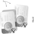
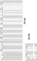
- Figure 69a is a table containing data relating to a few samples (samples No. 99 to 111) of blanks among over 10 000 pieces having been tested on February 7 th , 2012, by the Applicant, using a system and method for reducing giveaway material according to the present disclosure
- Figure 69b is a table summarizing data regarding all of the pieces having been tested/processed that day (the amounts listed in terms of weight are shown in "grams", and once again, this is merely an example shown for 1-ozt silver round coins as a possible "mint product").
- the pieces are sequentially brought or conveyed up to a scale (121), where each piece is weighed a first time. Afterwards, there is a visual recognition of the surface (i.e. outer body) of each piece, this step being optional and added in order to be very precise in the amount of targeted giveaway material being removed. Giveaway material is then removed via an appropriate processing process. In the example shown, a cutting feed is used while the product is being vertical displaced and rotated. Each piece is then weighed again to ensure that it is above a minimum threshold value (ex. in the case of "weight” used as a parameter of evaluation, and in the case of manufacturing 1-ozt silver coins, making sure that it weighs at least 1-ozt, etc.).
- a minimum threshold value ex. in the case of "weight” used as a parameter of evaluation, and in the case of manufacturing 1-ozt silver coins, making sure that it weighs at least 1-ozt, etc.
- an objective is to reduce giveaway material, and not necessarily to completely remove the entire "theoretical" giveaway material, given that the complete removal of the giveaway material on a given mint product (107) is very difficult due to tolerances of measuring and processing devices, as well as various other factors, as can be easily understood by a person skilled in the art.
- the present system (101) or method of reducing giveaway material can be used as an option at different locations of many conventional manufacturing process used in the production of mint products (107) and the like.
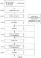
- FIG. 24 there is shown a schematic representation of a conventional multi-step process of manufacturing a mint product (107), such as in the context of the present description, a 1-ozt silver round coin for example, and where the present method of reducing giveaway material may be conveniently and optionally incorporated at different locations without affecting the overall disposition and/or layout of the overall conventional multi-step process.
- Step 1 the ingots or bars, which in the case of the present example, would be made of "silver", are typically melted and made out to take the form of coils. Afterwards, each coil will be typically brought to a desirable thickness via a laminating process. An annealing process usually follows, and blanking generally takes place afterwards, where blanks are cut out from the laminated sheet of precious metal (in our example, "silver”), similarly to what one would expect to see with a "cookie-cutter".
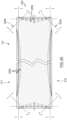
- the blanks In the case of the 1-ozt silver round coins manufactured by the Applicant, the blanks generally have an overall "circular" shape, as better shown in Figure 33A , 59a or 60a , although various suitable shapes may be used according to the present invention, as exemplified in Figures 33B-33J , and as can be easily understood by a person skilled in the art.
- a rim (203) may then be produced on each of the blanks about its peripheral edge, by typically compressing the diameter, the rim (203) being preferably intended to avoid that the obverse and reverse surfaces (205,207) of the resulting coin from being scratched (for example, in subsequent steps of the manufacturing process, etc.).
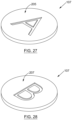
- the mint product (107) according to the present invention need not be provided with rims (203), as exemplified in Figures 34, 36 and 65 , and as can also be easily understood by a person skilled in the art.
- the products (107) may then be pre-washed or "wash-to-anneal" (1 st burnishing).
- the blanks may be subject to a liquid mixture of small ball bearings or pellets, cleaning agent(s) (such as soap, for example) and water in an attempt to remove as much impurities as possible, removing sharp edges, and to provide the blanks with desirable visual features, such as "shininess".
- a "burnish-to-strike" (2 nd burnishing) may take place afterwards, and typically, after this step, products are generally manipulated by workers with gloves and about the peripheral side edges (209) of each product so as to avoid that any oily residues from hands may adversely effect results in subsequent steps, such as in the striking step, for example, given that this type of step is very sensitive to impurities, and the presence of such unwanted impurities may greatly affect in an adverse manner the resulting quality of the product.
- a striking process which may be a "single strike” or a “double strike”, as will be explained in greater detail hereinbelow.
- the giveaway recovery method can be used as an "option" at different locations on a conventional multi-step manufacturing process, without substantially disrupting the layout or the nature of the existing manufacturing process being used.
- the present giveaway recovery method can be easily and conveniently incorporated between two standard steps of a conventional process of manufacturing a mint product (107), without having to substantially modify the sequence or equipment of the overall process.
- the present giveaway reducing method could ultimately be used after the striking step as well.
- Striking is a step within the overall process manufacturing of a mint product (107) where effigy (211) is placed or marked onto the product (107).
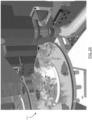
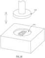
- the piece is inserted into the die (213), and the upper press (215) or clamp strikes down onto the piece so as to create the effigy (211) on the observe and/or reverses sides (205,207), where the effigy (211) can be an engraving and/or an embossment, as can be easily understood when referring to Figures 25-30 .
- the present invention is particularly advantageous in that it works for both "single struck” and “double struck” pieces.
- Single striking allows for a greater output of products (107), but double striking technically allows for products (107) of greater quality, in terms of surface finish, etc.
- Double striking is typically used for numismatic products because striking the product twice enables the material to flow even more within the die (213), and thus also in turns enables the effigy (211) to have a richer and fuller "body” (i.e. more "relief", etc.).
- Double striking could also be used for some bullion investment products, where, as mentioned earlier, the quality of the surface finish may also be sought after.
- the choice of location for removal of giveaway material on a given product (107) to be processed can be varied, as can be easily understood by a person skilled in the art from referring to the accompanying drawings, namely Figures 38 and 65 .
- a method, per se not encompassed by the appended claims, of reducing giveaway material from a plurality of mint products (107) each having different physical parameters comprising the steps of: a) evaluating at least one physical parameter of a given mint product (107) to be processed; b) comparing said at least one physical parameter of the mint product (107) to be processed with a minimum threshold physical parameter in order to determine an attainable range of giveaway material to be removed; c) projecting a targeted amount of giveaway material to be removed from the mint product (107) to be processed depending on, or as a function of, the attainable range of giveaway material; and d) removing the targeted amount of giveaway material via at least one surface of the mint product (107).
- a main object of the present invention is to reduce as much as possible the amount of giveaway material on a given product (107) to be processed, and that this amount is generally evaluated in terms of weight.
- the at least one physical parameter evaluated in step a) is not necessarily limited to "weight" per se , but may be any other type of physical parameters to be used, individually or in combination with others, to establish features of the mint product (107) to be processed, and in order be able to compare them with minimal threshold physical parameter(s), in order to enable to determine the attainable range of giveaway material to be removed, the best manner in which to reduce and/or remove a targeted amount of giveaway material, and other considerations.
- step a instead of just evaluating weight as a physical parameter in step a), one could ultimately evaluate the volume of the mint product (107) to be processed, and using an appropriate density, which could be pre-established or that could also be evaluated in step a), would be able to determine the initial weight of the mint product (107) to be processed.
- step a if one knows that all the given mint products to be processed by the present invention have a substantially same "average" weight, then there is no need to explicitly evaluate said at least one parameter of the mint products (107) to be processed, and at least one other physical parameter of the mint products (107) may be evaluated in step a), if deemed appropriate, such as "hardness” for example, in order to establish the best possible operating parameter to be used afterwards during the processing of the mint product (107) in order to optimally remove the targeted amount of the giveaway material therefrom, etc., as can be easily understood by a person skilled in the art.
- the method of reducing giveaway material can be intended to individually and sequentially evaluate each of the mint products (107) to be processed, this method may be simplified or reduced to approximate steps, in that, for example, one not need to evaluate each physical parameter of each mint product (107) to be processed, in that, one could ultimately carry out the present invention based on 3D models or approximations (using empirical data, averages, etc.).
- step a) instead of individually weighing each mint product (107) to be processed, which could correspond to a given embodiment of step a), such step a) could be simplified to simply assign an average weight (or other average parameter value) to a given batch of mint products (107) to be processed.
- each mint product (107) can be processed with a minimum threshold physical parameter in order to determine an attainable range of giveaway material to be removed
- step c Another variation, not in accordance with the appended claims, could also to not explicitly carry out step c), in that, one may decide to simply pass mint products (107) to be processed according to the present invention through an evaluation step to see how they compare with respect to a minimum threshold physical parameter, and then directly have them proceed to a processing assembly (111) of the machine (103) so as to remove an approximate targeted amount of material via at least one surface of each mint product (107), after which, such mint products (107) having been processed in a first stage, would be reevaluated to see how they compare with respect to said minimum threshold physical parameter to be respected, and depending on the result, another "loop" of processing (i.e. giveaway material reduction) could take place.
- step c) is not a "hard” step of individually calculating, but could also translate into simply approximately or nominally determining, assigning, aiming or projecting the targeted amount of giveaway material to be removed from each product (107) to be processed, whether it be in response to the evaluation of at least one physical parameter of said mint product (107), or based on at least one physical parameter having been approximated or pre-established based on an evaluation of a plurality of mint products (107), or other factors.
- step a) preferably comprises the step of assigning an identifying tag (ex. label, number, etc.) to each one of the plurality of mint products (107) to be processed, and further comprises the step of individually evaluating at least one physical parameter of each one of said mint products (107) to be processed.
- an identifying tag ex. label, number, etc.
- step a) preferably comprises the step of assigning an identifying tag (ex. label, number, etc.) to each one of the plurality of mint products (107) to be processed, and further comprises the step of individually evaluating at least one physical parameter of each one of said mint products (107) to be processed.
- step b) may comprise the step of rejecting a mint product (107) if the at least one physical parameter of said mint product (107) is below the minimum threshold physical parameter.
- evaluating at least one physical parameter of a mint product (107) to be processed consists in evaluating the initial weight of the mint product (107) before it is even processed, then if the weight of such mint product (107) is below the minimum physical threshold physical value that is being sought, such as the minimal legal trade weight for said mint product (107), then the mint product (107) is simply rejected so that it may be reutilized in an appropriate manner (for example, it may be re-melted, so as to be reused again under at least a minimal appropriate weight, etc.).
- step c) comprises the step of scanning the mint product (107) to be processed so as to recreate a geometrical profile thereof, or at the very least, to obtain visual information from the product (107) that can be used for processing thereof.
- step c) comprises the step of scanning the mint product (107) to be processed so as to recreate a geometrical profile thereof, or at the very least, to obtain visual information from the product (107) that can be used for processing thereof.
- scanning of the mint product (107) to be processed is done by relatively rotating the mint product (107) with respect to a scanner (145), and preferably, it is the mint product (107) that is rotated with respect to the scanner (145) for obtaining a dimensional representation of said product (107), but depending on the particular applications and end results for which the present system (101) could be used, it is worth mentioning that other types of assemblies can be employed appropriately.
- step c) would be carried out in a context where the mint product (107) to be processed by the present invention would be conveyed through a scanning assembly (145), and that the mint product (107) would be fixed with respect to the scanning assembly (145) which could be fixed or not. Therefore, it can be easily understood that a relative movement between the mint product (107) to be scanned and the scanning assembly (145) may not be required so as to obtain an appropriate visual information from said product (107) to be processed according to the present invention.
- scanning of the mint product (107) to be processed is preferably done by relatively rotating the mint product (107) with respect to a scanner (145), as can be easily understood when referring to Figures 40 and 41 , for example.
- One of the main advantages of proceeding as such is that, advantageously, the are combined the scanning of the mint product (107) and the processing thereof (for example, cutting or removing of excess giveaway material) at a same given location, which is beneficial for attaining high outputs of processed mint products (107), in that less time is wasted compared to if the mint product (107) was first scanned in a first given location of the system (101), and then displaced in order to be processed or machined in another physical location of the system (101), etc.
- the mint product (107) to be scanned is preferably centered or positioned with respect to a fixed point (141) of reference line (139), but in the event of the mint product (107) being uncentered, preferably scanning of the mint product (107) is carried out in order to take into account such misalignment or uncentering.
- a person skilled in the art will understand that there are various ways of appropriately recreating a dimensional representation of the mint product (107), and compensating for any deviations that may result from the positioning of the mint product (107) or from the equipment being used for scanning.
- the step c) preferably comprises the step of geometrically calculating the targeted amount of giveaway material to be removed. Namely, based on the initial weight of the mint product (107) having been evaluated in step a) for example, and a volumetric or geometric scanning of the product (107), one can determine the amount, which in this case will take the form of volume, of giveaway material to be removed from the mint product (107) to be processed.
- step c) preferably comprises the step of taking into account a tolerance from the process or equipment used in step d) to ensure that the at least one physical parameter of the mint product (107) still exceeds the minimum threshold physical parameter after giveaway material has been removed from said mint product (107). For example, if one always wants 31.109 grams as a minimal value on the final product (107), and taking into account that the tolerance of the process of reducing giveaway material is about +/- 20 mg, this translates into a minimal value that could be targeted of about 31.129 mg, which, as a preventive measure, could be rounded off to about 31.130 mg.
- the method could be simply reduced to a) removing giveaway material from a plurality of mint products (107), and then simply b) evaluating said processed mint products (107) to see which ones are above the minimum threshold, in which case, these processed pieces could be "accepted” (or reprocessed a little bit more, via another passage, if desired, etc.), and to see which ones are below the minimum threshold, in which case these processed pieces could be "rejected”.
- the targeted amount of giveaway material to be removed in step d) will be generally proportional to the attainable range of giveaway material determined in step b), especially if one wants to "maximize” the amount of giveaway material to be reduced/removed from what is possible on each mint product (107) to be processed.
- different modifications or simplifications can be made to the present system (101) or method without departing from the scope of the present invention, which ultimately resides in reducing giveaway material from a given mint product (107), in that, one could decide to only remove a "fixed” amount of giveaway material from each mint product (107) to be processed, irrespectively of the attainable range of giveaway material to be removed in each one of said mint products (107).
- Removal of giveaway material of the mint product (107) to be processed can be carried out in many ways, but according to a preferred embodiment of the present invention, removal of giveaway material in step d) is done by displacing the mint product (107) with respect to a processing tool (227) along at least one degree of motion, whether it be a rotational component, an x-y-z component, a radial component, etc., as can be easily understood by a person skilled in the art.
- removal of giveaway material in step d) is done by relatively displacing the mint product (107) to be processed vertically with respect to a processing tool (227), and preferably also, removal of giveaway material in step d) is done by relatively rotating the mint product (107) to be processed with respect to the processing tool (227).
- a single cutting tool (151) is used as a processing tool (227), and this very same cutting tool (151) could be used for carrying out different cutting profiles thanks to at least two degrees/ranges of motion of the mint product (107), namely a vertical displacement (1 st degree or range of motion) of the mint product (107) to be processed, while said mint product (107) is being rotated (2 nd degree or range of motion).
- the mint product (107) to be processed is rotated at a rate of about 3500rpm.
- the present system (101) can also offer a 3 rd degree or range of motion, in that, according to a preferred embodiment of the machine (103), the cutting tool (151) is meant to move forwards and backwards, therefore, there is a linear displacement of the cutting tool (151), as can be easily understood when referring to Figures 39 and 41 .
- An important advantage of the present invention is that it enables for adaptability in various ways of removing giveaway material from different portions or parts of various different types of mint products (107) to be processed, and as a result, one way of removing giveaway material in step d) could be done using at least one cutting profile (229) selected from a predetermined said of cutting profiles (229) which would cover a wide array of practically all different possibilities that would be required for certain given applications to be intended with the present system (101) or method.
- the present system (101) and method could be simplified, and ultimately, one could decide to have one single cutting profile (229) to be used on all mint products (107) of a given batch to be processed with a system (101) or with the method.
- the present method could ultimately be simplified to the following two (2) steps: a) conveying a plurality of mints products to be processed; and b) processing at least one given mint product at a time, so as to remove an amount of giveaway material from each one of the mint products.
- removal of giveaway material in step d) is preferably done using at least one cutting profile (229) selected depending on an amount of giveaway material to be removed, and more particularly, and preferably also, depending on an amount of giveaway material to be removed on the particular mint product (107) to be processed, after it has been individually evaluated.
- the different cutting profiles (229) being selected in response to the particularities of a given mint product (107) to be processed may be carried out with a single cutting tool (151), or with a plurality of different cutting tools (151) selected based on the array of different cutting profiles (229) provided by the system.
- a single cutting tool 151
- a plurality of different cutting tools 151) selected based on the array of different cutting profiles (229) provided by the system.
- a chamfer cutting profile (229a) may be used when there is a given range (ex. "minimal” range) of amount of giveaway material to be removed from the mint product (107) to be processed.
- a chamfer cutting profile (229a) could be used when there is a range of about 0-100 mg to be removed from each mint product (107) to be processed, this chamfer cutting profile (229a) being illustrated for example in Figures 38 and 65 .
- a curvilinear cutting profile (229b) may be advantageously used when there is another given range (ex. "intermediate" range) of amount of giveaway material to be removed from the mint product (107) to be processed.
- the curvilinear cutting profile (229b) is very useful when having to remove about 100-300 mg from each mint product (107) to be processed.
- a radial-component reducing cutting profile (229c) or flat-edging can also be used when the amount of giveaway material to be removed exceeds a given range (i.e. "maximum” range) of amount of giveaway material to be removed from the mint product (107) to be processed.
- a given range i.e. "maximum” range
- this type of cutting profile (229) is particularly useful when having to remove about 300 mg or more.
- a circular mint product (107) such a blank for example, as used in our illustrative case of a 1-oz silver round coin
- the step of radial-component reducing cutting profile (229c) or flat-edging could correspond to an advance of the cutting tool (151) of about 0.05mm for example, which would correspond to the removal of about 175mg, thereby creating a new reference surface (209) to work with, as can be easily understood by a person skilled in the art.
- chamfering might take a little bit longer to execute, because when a single cutting tool (151) is being used (see for example Figure 41 ), it as to do two passes (top and bottom), whereas in the case of a curvilinear cutting profile (229b), the tool (151) just has to do one pass (going in and coming out while the mint product is being rotated), therefore, in terms of cadence, the curvilinear and radial-component reducing cutting profiles (229b, 229c) might be more advantageous than the chamfering one, for certain applications.
- curvilinear cutting profile (229b) is preferably used to cover both cases ("minimal” range of about 0-100 mg, and “intermediate” range of about 100-300mg).
- minimal range of about 0-100 mg
- intermediate range of about 100-300mg.
- the machine (103) is intended to advance of just a few microns, while removing giveaway material about a wide span (231) of the surface to be processed, and can remove quantities as little as about 30mg.
- the advantage of removing giveaway material along a very wide span (231) of the surface to be processed is that one does not need to going in as deeply into the product (107) for a given amount of material as with a narrower span (231), and the angle of attack or slope on entry point and exit point is not as abrupt, thereby contributing to a better overall visual finish (less likelihood of marks on the final product (107) after striking).
- a radial-component reducing or flat-edging cutting profile (229c) can simply be a special case of a curvilinear cutting profile (229b) where said curvilinear cutting profile is "straight", and introduced radially inwardly into the mint product (107) to be processed, as apparent to a person skilled in the art when referring to Figure 63 .
- the present system (101) or method for reducing giveaway material is not necessarily limited to "circular” mint products (107), and that is why the term “radial-component reducing cutting profile (229c)" has been used instead of a “diameter-reducing cutting profile", because ultimately various other types of suitable forms instead of just circular, such as rectangular shapes, for example, in the case of wafers or bars, could also be processed according to the present invention in which case, a radial-component cutting profile (229c) would be used to reduce an outer edge or portion of such mint product (107). Indeed, one can imagine the use of a router bit, for example.
- step d) removal of giveaway material in step d) is done within a proportion of a full extent (233) of the least one surface of the mint product (107) where giveaway material is removed from.
- the surface about which the giveaway material is to be removed can be any suitable surfaces or portions of the mint products (107), depending on the particular application for which the mint product (107) is intended for, and the desired end results.
- an object of the present invention is also to ensure that removal of giveaway material on the resulting product (107) of said processed mint product (107) is practically unnoticeable, or at the very least, satisfies a given criteria of a visual quality assurance, it has been found that the side surface is an ideal surface (209) for removal of giveaway material, as exemplified in Figure 39 , given that according to a preferred embodiment of the present invention, an ideal location for removing giveaway material within the manufacturing process of a given mint product (107) is just before the striking step, because, following the striking step, there is generally no further loss of material, and the striking step is a convenient way of masking or concealing any giveaway material having been removed from the product (107) according to the present invention.
- the above-mentioned proportion is at least about 60% of the full extent (233) of the least one surface of the mint product (107) where giveaway material is removed from.
- the proportion is at least about 90% of the full extent (233) of the least one surface of the mint product (107) where giveaway material is removed from, and for even better results, it is preferable that the proportion be between about 90% and about 95% of the full extent (233) of the least one surface of the mint product (107) where giveaway material is to be removed from.
- a narrow span (231) of material removal is more likely to be noticeable on the final product (107), and other extensive studies and tests carried out by the Applicant have shown that it is best if material removal is done over the largest span (231) possible of a given surface (ex. around 95% of full extent span (233)). Indeed, one should strive to maximize the span (231) of the surface over which giveaway material is removed.
- the percentage of span (231) with respect to the full extent (233) of the surface is kept a fixed parameter (for example, about 95% of a side surface in the case of a 1-oz silver round coin), and the amount of giveaway material (depth, profile of material removal, etc.) is the variable parameter and is removed as a function of the first parameter and other considerations.
- step d) removal of giveaway material in step d) is done in accordance with at least one operating parameter, having been selected based on the particular applications for which the present invention is intended for, and the desired results.
- the at least one operating parameter is selected depending on at least one physical parameter of the mint product (107) to be processed, which could be the same as that or those evaluated in step a) of the method according to the present disclosure, or based on at least one other physical parameter of the mint product (107) to be processed, such as for example, weight, dimension, geometric profile, type of material, purity of material, material density and material hardness of the mint product (107) to be processed, for example, as can be easily understood by a person skilled in the art.
- a main operating parameter to be considered is the cutting feed rate to be used.
- a cutting tool (151) particularly used for our example of a 1-oz silver round coin, is a carbide cutting tool (151) having a rounded cutting tip (235), the rounded cutting tip (235) having a radius of about 0.02 mm which enables very precise and versatile cutting profiles (229).
- the cutting feed is between about 0.04 mm and about 0.12 mm per rotation of the mint product (107) to be processed.
- this type of such a carbide cutting tool (151) is advantageous in that it is a very inexpensive tool and does not introduce any other elements that may harmful to chemistry of the material (e.g. silver, in the example described herein) of the mint product (107) to be processed. Therefore, it is a very good compromise in terms of durability, performance and cost.
- the cutting tool (151) is also provided with a chip-breaker (237), similar to a "pelican's beak", for cutting the shavings in lengths of a predetermined length, such as about 0.5-1 inch, for example, so as to avoid accumulation and/or forming of nests of shavings within the machine (103) which is undesirable for obvious reasons.
- giveaway material there may be other various ways of removing giveaway material according to the present invention, and as way of example, removal of giveaway material in step d) could be done by a process selected from the group consisting of polishing, brushing, grinding, machining, milling, drilling, chemical etching, using a laser, etc.
- suitable ways of removing giveaway material from a mint product (107) to be processed according to the present invention could be used, as can be easily understood by a person skilled in the art, and furthermore, the giveaway material need not to be limited to be removed in a form of shavings, but it could also be removed in the form of dusts, particles, fumes, liquid extracts, or any other suitable forms, as also apparent to a person skilled in the art.
- removal of giveaway material in step d) is preferably done so as to leave a non-polished surface on the least one surface of the mint product (107) where giveaway material is removed from.
- removal of giveaway material in step d) is done so as to leave a plurality of surface grooves (239) on the least one surface of the mint product (107) where giveaway material is removed from.
- removal of giveaway material in step d) can be done via at least one surface (portion, edge, rim, etc.) of the mint product (107) to be processed, and different types of surfaces (portions, edges, rims, etc.) may be selected, such as for example, a top surface (217), a bottom surface (219), a side surface (209), a rim (203) of the mint product (107) to be processed, or any other suitable surfaces or portions thereof.
- the targeted amount of giveaway material to be removed in step d) is removed from a side surface (209) disposed between opposite obverse and reverse surfaces (205,207) of the mint product (107) to be processed.
- the mint product to be process is generally a substantially solid mint product, having top and bottom surfaces (217,219), and a side surface (209) extending therebetween.
- the mint product (107) may also comprise at least one rim (203) (see different examples illustrated in Figures 45a-45f ), and in such a case, typically comprises top and bottom rims (203a,203b).
- the mint product to be processed by the present invention can take on various different overall geometrical shapes, in that it can be round, polygonal, triangular, rectangular, square, pentagonal, hexagonal, heptagonal and octagonal for example, as exemplified in Figures 33A-33J , but it may also take on various other non-symmetrical shapes, and very different "unusual" shapes, in that, as is well known in the art, numismatic products can take the forms of animals, plants, and various other types of objects, whether 3D, or to a certain extent, could be considered as two-dimensional, in that if the thickness of the main product (107) is substantially "negligible" with respect to a top surface area, for example.
- system (101) and method according to the present disclosure may be used to process each of these different types of mint products (107), in which case, the components of the machine (103), or the steps of the method, could be easily altered or adjusted to accommodate these different types of mint products (107).
- peripheral portion (243) of the product (107) enables it to be properly positioned and secured within the collar (213), as can be easily understood when referring to Figures 59 , 60 , 61 and 64 , where top and bottom peripheral contact portions (243a,243b) of the processed mint product (107) (corresponding, for example, to about 5% of the full extent of the side surface (209)) would abut against an inner wall (245) of the collar (213), so as to avoid jumping of the product (107) during the striking step.
- a preferred embodiment of removing the targeted amount of giveaway material from the mint product (107) in step d) takes on the form of shavings, which can be easily recuperated and reprocessed, but it is worth mentioning that also, according to the present invention, the giveaway material of the mint product (107) to be done can be removed in various different other suitable forms, such as dusts, fumes, liquids (for example, if giveaway material is melted away from the product (107)), etc., as can be easily understood by a person skilled in the art.
- step d) removal of giveaway material in step d) is done using an abrasive assembly (251), for example, the machine (103) or method could be slightly altered to ensure that the mint product (107) to be processed is brought to and maintained with respect to the abrasive assembly (251), in order to appropriately remove the targeted amount of giveaway material, via at least one portion of said mint product (107).
- the mint product is not limited to a circular shape, but may take on various other suitable shapes (ex. rectangular, etc.) as explained earlier, and as can be easily understood by a person skilled in the art.
- the giveaway material removed from the mint product (107) in step d) complies with a given criteria of quality assurance in terms of visual appearance on the final mint product having been processed.
- an object of the present invention was to not only enable the reducing and recovering of giveaway material from products (107) made of solid precious metals, but also to ensure that the removal of the giveaway on the resulting products (107) of said processed mint products (107) was practically unnoticeable, or at the very least, would satisfy a given criteria of visual qualify assurance.
- step d) is carried out in a controlled confined environment in order to prevent loss of giveaway material from said environment
- the method further comprises the step of e) recuperating giveaway material having been removed in step d).
- step e) is carried out in a controlled confined environment in order to prevent loss of giveaway material from said environment.
- the step e) of recuperating giveaway material having been removed in step d) is done by allowing the giveaway material having been removed to fall within a desired location via gravity, so as to subsequently recuperate said giveaway material having been removed.
- step e) could also include the step of sucking giveaway material having been removed in step d) with a suction assembly (189), and step e) could also include the step of filtering giveaway material having been removed in step d) with a filtering assembly (253).
- a looping feature to the system (101) or method of reducing giveaway material in that the method could further comprise the steps of re-evaluating said at least one physical parameter of the mint product (107) (i.e. another step a)); and repeating either one of the subsequent steps (step b, c or d) if the mint product (107) still contains an amount of giveaway material that is outside a predetermined range of allowable tolerances.
- the present system (101) or method of reducing giveaway material can be done on finished mint products, or can be carried out on intermediate mint products (107) not having yet been finished, and according to a preferred embodiment of the present invention, as exemplified in Figure 24 , the system (101) or method is incorporated into a manufacturing process, and the mint product (107) on which giveaway material is removed and recovered is a "blank", preferably before the striking step, although material removal could ultimately be done on a blank at other suitable location(s) within the manufacturing process, as also exemplified in Figure 24 .
- the system and method could be altered or adjusted accordingly.
- step a) could comprise the steps i) providing a blank; and ii) evaluating at least one physical parameter of the blank.
- step i) could comprise the step of providing a plurality of blanks
- step ii) could comprise the step of evaluation at least one physical parameter of each blank on an individual basis, as mentioned earlier when referring to the operation of the machine (103).
- Step b) could comprise the step of rejecting a blank if the at least one physical parameter of said mint product (107) is below the minimum threshold physical parameter, and similarly to what was discussed earlier, the at least one physical parameter of step a) could be selected from the group consisting of weight, dimension, geometric profile, type of material, purity of material, material density and material hardness of the mint product (107) to be processed, and/or other criteria, as can be easily understood by a person skilled in the art.
- the percentage of giveaway material is higher with respect to smaller products (107) (ex. less than about 100 ozt), then with respect to bigger products (107).
- the present invention is particularly advantageous when used with mint products (107) weighing less than about 101 ozt, such as 100 ozt for example, 1 kg, 10 oz, 5 oz, 2 oz, or 1 oz, for example.
- the present invention could also be used on mint products (107) that are even smaller than the above-mentioned examples given.
- the minimum threshold physical parameter according to a preferred embodiment of the present invention is preferably less than about 101 troy ounces (ozt).
- the minimum threshold physical parameter is about 31.1034768 grams.
- the principles of the present invention i.e. "giveaway material reduction" could still be used on such big products, in which case, components and parameters of the system (101) and/or the method could me modified, simplified, altered, omitted and/or interchanged accordingly, as apparent to a person skilled in the art. For example, conveyor belts, scales, etc. being used would be made more robust, etc.
- the minimal threshold physical parameter may be very different depending on the particular applications for which the present invention is intended for, and the different types of objects or materials used therewith.
- the minimum threshold physical parameter is at least about 31.1066 grams when the mint product (107) to be processed is made of silver having a purity of about 99.99%, whereas, the minimum threshold physical parameter is about 31.1346 grams when the mint product (107) to be processed is made of silver having a purity of about 99.9%, and the minimum threshold physical parameter is about 33.9298 grams when the mint product (107) to be processed is made of 22-carat gold.
- the present system (101) or method of reducing giveaway material can be used on various types of different mint products (107), whether they be finished mint products (107), or intermediate products (107) thereof, such as for example, a bullion product, an investment product, a numismatic product, a circulation product, a medal product, a medallion product, a bar product, an ingot product, and a token product.
- the mint product (107) could also be a "blank", that is, an intermediate product (107) used in the overall manufacturing process of a mint product (107), irrespectively of whether it is circular or not.
- the present invention is not limited to "mint products” (107) per se , but could be use on any other types of products (107) made of solid precious metals, where giveaway material is to be reduced/removed and advantageously recovered.
- the present invention could also be used on certain types of products (107), such as coins used for recreational purposes and the like, for example, where the product (107) need not be made of a solid precious metal, etc., as can be easily understood by a person skilled in the art.
- the mint product (107) is a final end product (107) having been processed by a machine according to the present invention, so as to obtain a bullion investment product, which contains or is made of a precious metal, and generally, such mint product (107) is made of solid precious metals selected from the group consisting of gold, silver, platinum and palladium, although other types of precious metals (ex. rhodium, iridium, osmium, rhenium, ruthenium, etc.), and various other types of different forms (ex. sponge-like, powder-like, etc.), could also be processed with the present invention.
- the method is an automated method carried out via a corresponding machine (103) according to the invention, such as the one exemplified in Figures 1-23 , and preferably, this automated method processes a given output of products per minute, such output being adjustable by selectively adjusting corresponding parameters of the machine (103) or process.
- the present system (101) or method of giveaway material recovery can be used as an optional and/or complementary feature, on a conventional multi-step manufacturing process, without substantially disrupting the layout or the nature of the existing manufacturing process being used, and can be introduced at different locations within the manufacturing process.
- the method of reducing giveaway material could be carried out between a blanking step and a rimming step of the multi-step process of the manufacturing the mint product (107).
- the present method could also be carried out between a rimming step and a burnishing step.
- the present method could also be carried out between a burnishing step and an annealing step.
- the present method could be carried out between an annealing step and a burnishing step.
- the method of reducing giveaway material is carried out just before a striking step of the multi-step of process of manufacturing the mint product (107), such as between a second burnishing and a striking step, for example, as exemplified in Figure 24 .
- a giveaway material recovery according to the present invention just before a striking step is advantageous in that following the striking step, there is generally no loss of material, and the striking step is a convenient way of masking or concealing any giveaway material having been removed from the product (107) according to the present invention, for an optimal surface finish of the mint product (107).
- a user of the present invention may decide to apply the present invention at other locations or stages of a manufacturing/processing process, for different reasons, and that the use of a method of giveaway material is not limited to just before a striking step, as can also be easily understood by a person skilled in the art.
- the product when a product material is "hard” (for example, about 56 Rockwell), the product tends to be more visually appealing, and is less likely to be subject to have little surface defects, imperfections, notches, scratches, etc.
- a blank when a blank is hard, it is also more difficult to strike.
- the mark being struck on the product (107) is much more challenging in terms of attaining the desirable end visual effect, especially in the case where the effigy (211) comprises an embossed or elevated portion, etc.
- a much higher tonnage is required, and as a result, the dies have a shorter lifespan.
- an important aspect of the present invention is that the system (101) and method of giveaway material can be used on products having different types of hardness, given that the present method of reducing giveaway material may be conveniently and optionally incorporated at different locations without affecting the overall disposition and/or layout of the overall conventional multi-step process.
- Striking of the mint product (107) can be carried out in various different ways, such as for example: a) a mint product (107) can be single struck during the striking step; b) the mint product (107) can be double struck during the striking step; c) the mint product (107) can be struck with a plain collar (213); d) the mint product (107) can be struck with a serrated collar (213); etc.
- the method of reducing giveaway material could ultimately be carried out after a striking step, if the visual appearance of the material having thus been removed is not a deterrent for the particular applications or purposes for which the mint product (107) is intended for.
- a mint product (107) having been processed with a machine (103) according to the present invention there is also provided a mint product (107) having been processed with a machine (103) according to the present invention.
- the products (107) meant to used with the present invention are not necessarily limited to products (107) manufactured by or for mints, but rather can be any variety of products made of precious metals where there may be a need or an advantage to have giveaway material be removed, etc., and also that, in the case where the products (107) being processed are blanks, the blanks can be manufactured on location, or can be purchased from corresponding providers, etc., as can be easily understood by a person skilled in the art.
- the machine (103) according to the present invention can be used on "new" products (107) or “old” products (107), on “finalized” products (107) or “intermediate” products (107) thereof, at “one” or “several” stages of a manufacturing or processing process of the product (107), and irrespectively of whether the product (107) is provided with a visual mark (ex. effigy, etc.) or not.
- the present invention may be used for by various other types of entities than mints (refiners, smelters, etc.), with various other types of objects (cast bars, minted bars, minted coins, coin blanks, medallions, ingots, etc., even if these products (107) are unmarked or un-engraved, etc.), made of various other types of materials (gold, platinum, palladium, etc.) and in various other types of different forms (substantially solid form, sponge-like, etc.), without departing from the scope of the present invention, as can be easily understood by a person skilled in the art.
- the components of the machine according to the present invention are made of suitable materials, for properly sustaining the different loads to which the station may be subjected to and other parameters to be considered, as apparent to a person skilled in the art.
- the system (101) may include one or several of the following: a collection box (255) for shaving vacuum extraction; at least one robot (257); an electrical cabinet (259); a vacuum generator (261); a main spindle drive (263); a Z-spindle drive (265) for moving blank to tool by a certain distance (ex.
- the present invention is a substantial improvement over the prior art in that, by virtue of its design and components, as briefly explained herein, the machine (103) according to the present invention overcomes several of the aforementioned prior art problems, providing for easy, accurate, functional and versatile system for reducing and/or removing, and recovering, giveaway material.
- the present invention is advantageous over the prior art in that, for example: a) it enables to reduce and to recuperate giveaway material from a product (107) which normally would be simply "given away”; b) depending on the nature of the machine (103) and/or of the method, this manner of reducing and recovering giveaway material can be done in a very precise, systematic and repeatable manner; c) this translates in tremendous savings, particularly when the nature of the giveaway material being recovered is a precious metal; d) removal of the giveaway material can be conveniently carried out at different given location(s) of an existing conventional manufacturing process; e) giveaway material reduction from a given mint product (107) can also be done so as to ensure that the removal of the giveaway material on the resulting product (107) of said processed mint product (107) is practically unnoticeable, particularly when giveaway material is reduced just before a striking step; f) the present system and method can be used on products (107) having different types of hardness; g) the present system and method can be used on products (107) having different types of collars; h)
- Another substantial advantage of the present invention is that the use of the present machine is not limited to the manufacturing or processing of new mint products (107), but ultimately, could be used on existing products (107), that are already in circulation, etc.
Landscapes
- Life Sciences & Earth Sciences (AREA)
- Forests & Forestry (AREA)
- Engineering & Computer Science (AREA)
- Mechanical Engineering (AREA)
- Physics & Mathematics (AREA)
- General Physics & Mathematics (AREA)
- Adornments (AREA)
- General Factory Administration (AREA)
- Multi-Process Working Machines And Systems (AREA)
- User Interface Of Digital Computer (AREA)
- Adjustment And Processing Of Grains (AREA)
Claims (10)
- Machine (103) pour réduire le matériau excédentaire d'une pluralité de produits de monnaie (107) ayant chacun des paramètres physiques différents, selon un procédé de réduction de matériau excédentaire, dans laquelle le procédé comprend les étapes de :a) évaluation d'au moins un paramètre physique d'un produit de monnaie (107) donné à traiter, ledit au moins un paramètre physique étant représentatif d'un poids initial ;b) comparaison dudit au moins un paramètre physique à un seuil minimum de paramètre physique étant également représentatif du poids afin de déterminer une plage atteignable de matériau excédentaire à retirer ;c) projection d'une quantité ciblée de matériau excédentaire à retirer du produit de monnaie (107) à traiter en fonction de la plage atteignable de matériau excédentaire ; etd) élimination de la quantité ciblée de matériau excédentaire par au moins une surface du produit de monnaie (107) ; etdans laquelle la machine (103) comprend :- un ensemble de transport (109) pour transporter une pluralité de produits de monnaie à traiter ;- un ensemble de traitement (111) pour traiter au moins un produit de monnaie (107) donné selon les étapes a) à d), l'ensemble de traitement (111) comprenant un ensemble de pesage (119) pour peser le produit de monnaie (107) à traiter selon l'étape a), un ensemble de balayage (145) pour balayer le produit de monnaie (107) à traiter et pour générer un profil correspondant de celui-ci selon l'étape c), et un ensemble de retrait de matériau (147) pour retirer le matériau excédentaire du produit de monnaie (107) ; dans laquelle ladite étape c) comprend le calcul géométrique, sous forme de volume, de la quantité ciblée de matériau excédentaire à retirer du produit de monnaie (107) à traiter, sur la base du poids initial du produit de monnaie (107) ayant été évalué à l'étape a) et d'un balayage volumétrique ou géométrique du produit de monnaie (107) ; et- un ensemble de récupération (113) pour récupérer les produits de monnaie (107) ayant été traités.
- Machine (103) selon la revendication 1, dans laquelle l'ensemble de pesage (119) comprend au moins une balance (121) reposant de manière opérationnelle sur une surface au sol (123) par l'intermédiaire d'au moins un ensemble d'amortissement des vibrations (125), et dans laquelle ladite balance (121) est isolée de manière opérationnelle du reste de la machine (103).
- Machine (103) selon l'une quelconque des revendications 1 à 2, dans laquelle l'ensemble de traitement (111) comprend au moins un carrousel rotatif (129) ayant des poches (131) pour recevoir une pluralité de produits de monnaie (107) à traiter.
- Machine (103) selon l'une des revendications 1 à 3, dans laquelle l'ensemble de traitement (111) comprend un ensemble de manipulation (133) pour manipuler les produits de monnaie (107) à traiter, et dans laquelle l'ensemble de manipulation (133) comprend de préférence au moins un bras articulé (135).
- Machine (103) selon la revendication 4, dans laquelle l'ensemble de manipulation (133) comprend un ensemble de centrage (137) pour centrer chaque produit de monnaie (107) à traiter par rapport à un point de référence correspondant.
- Machine (103) selon l'une quelconque des revendications 1 à 5, dans laquelle l'ensemble de traitement (111) comprend des pinces (143a, 143b) pour serrer chaque produit de monnaie (107) à traiter.
- Machine (103) selon l'une quelconque des revendications 1 à 6, dans laquelle l'ensemble de traitement (111) est configuré pour faire tourner chaque produit de monnaie (107) à traiter par rapport à un point de référence (141) correspondant.
- Machine (103) selon l'une quelconque des revendications 1 à 7, dans laquelle l'ensemble de traitement (111) est configuré pour déplacer verticalement chaque produit de monnaie (107) à traiter par rapport à un point de référence (141) correspondant.
- Machine (103) selon l'une quelconque des revendications 1 à 8, dans laquelle l'ensemble de retrait de matériau (147) comprend un ensemble de coupe (149) pour couper le matériau excédentaire du produit de monnaie (107) à traiter.
- Machine (103) selon l'une quelconque des revendications 1 à 9, dans laquelle l'ensemble de traitement (111) comprend un ensemble informatique (155) pour la réception et le traitement de données associées aux produits de monnaie (107) et pour l'ajustement des paramètres de la machine (103) en fonction desdites données.
Priority Applications (2)
| Application Number | Priority Date | Filing Date | Title |
|---|---|---|---|
| EP25173730.0A EP4570510A3 (fr) | 2011-03-28 | 2012-03-28 | Système et procédé de réduction de matière à donner du goût sur des produits de menthe |
| SI201232093T SI3841912T1 (sl) | 2011-03-28 | 2012-03-28 | Stroj za zmanjševanje odpadnega materiala pri kovniških izdelkih |
Applications Claiming Priority (6)
| Application Number | Priority Date | Filing Date | Title |
|---|---|---|---|
| US201161468385P | 2011-03-28 | 2011-03-28 | |
| US201161510848P | 2011-07-22 | 2011-07-22 | |
| US201161540813P | 2011-09-29 | 2011-09-29 | |
| US201261603546P | 2012-02-27 | 2012-02-27 | |
| PCT/CA2012/050192 WO2012129691A1 (fr) | 2011-03-28 | 2012-03-28 | Système et procédé pour réduire le matériau excédentaire sur les produits de monnaie |
| EP12763154.7A EP2690981A4 (fr) | 2011-03-28 | 2012-03-28 | Système et procédé pour réduire le matériau excédentaire sur les produits de monnaie |
Related Parent Applications (1)
| Application Number | Title | Priority Date | Filing Date |
|---|---|---|---|
| EP12763154.7A Division EP2690981A4 (fr) | 2011-03-28 | 2012-03-28 | Système et procédé pour réduire le matériau excédentaire sur les produits de monnaie |
Related Child Applications (2)
| Application Number | Title | Priority Date | Filing Date |
|---|---|---|---|
| EP25173730.0A Division-Into EP4570510A3 (fr) | 2011-03-28 | 2012-03-28 | Système et procédé de réduction de matière à donner du goût sur des produits de menthe |
| EP25173730.0A Division EP4570510A3 (fr) | 2011-03-28 | 2012-03-28 | Système et procédé de réduction de matière à donner du goût sur des produits de menthe |
Publications (3)
| Publication Number | Publication Date |
|---|---|
| EP3841912A2 EP3841912A2 (fr) | 2021-06-30 |
| EP3841912A3 EP3841912A3 (fr) | 2021-09-29 |
| EP3841912B1 true EP3841912B1 (fr) | 2025-06-11 |
Family
ID=46929269
Family Applications (3)
| Application Number | Title | Priority Date | Filing Date |
|---|---|---|---|
| EP12763154.7A Ceased EP2690981A4 (fr) | 2011-03-28 | 2012-03-28 | Système et procédé pour réduire le matériau excédentaire sur les produits de monnaie |
| EP21153752.7A Active EP3841912B1 (fr) | 2011-03-28 | 2012-03-28 | Dispositif pour réduire le matériau excédentaire sur les produits de monnaie |
| EP25173730.0A Pending EP4570510A3 (fr) | 2011-03-28 | 2012-03-28 | Système et procédé de réduction de matière à donner du goût sur des produits de menthe |
Family Applications Before (1)
| Application Number | Title | Priority Date | Filing Date |
|---|---|---|---|
| EP12763154.7A Ceased EP2690981A4 (fr) | 2011-03-28 | 2012-03-28 | Système et procédé pour réduire le matériau excédentaire sur les produits de monnaie |
Family Applications After (1)
| Application Number | Title | Priority Date | Filing Date |
|---|---|---|---|
| EP25173730.0A Pending EP4570510A3 (fr) | 2011-03-28 | 2012-03-28 | Système et procédé de réduction de matière à donner du goût sur des produits de menthe |
Country Status (12)
| Country | Link |
|---|---|
| US (4) | US10029378B2 (fr) |
| EP (3) | EP2690981A4 (fr) |
| CN (1) | CN103957742B (fr) |
| AR (1) | AR092287A1 (fr) |
| AU (1) | AU2012234700B2 (fr) |
| CA (1) | CA2831624C (fr) |
| ES (1) | ES3044132T3 (fr) |
| PL (1) | PL3841912T3 (fr) |
| PT (1) | PT3841912T (fr) |
| SI (1) | SI3841912T1 (fr) |
| WO (1) | WO2012129691A1 (fr) |
| ZA (1) | ZA201308071B (fr) |
Families Citing this family (6)
| Publication number | Priority date | Publication date | Assignee | Title |
|---|---|---|---|---|
| ES2544495B1 (es) * | 2012-11-08 | 2016-06-23 | Monnaie Royale Canadienne / Royal Canadian Mint | Tecnicas mejoradas para la produccion de bronce dorado por interdifusion de estaño y cobre en condiciones controladas |
| DE102015117601A1 (de) * | 2015-10-16 | 2017-05-11 | Schuler Pressen Gmbh | Prüfvorrichtung zum Prüfen von Münzrohlingen |
| DE102017007900B3 (de) | 2017-08-19 | 2018-11-29 | Sack & Kiesselbach Maschinenfabrik Gmbh | Vorrichtung und Verfahren zum Prägen von Münzen oder Medaillen |
| IT201900015527A1 (it) * | 2019-09-03 | 2021-03-03 | Tera Automation S R L | Apparato e metodo per la messa a peso di semilavorati, particolarmente per semilavorati in metallo prezioso |
| EP4227653A1 (fr) * | 2022-02-14 | 2023-08-16 | DS4 S.r.l | Système pour amener automatiquement des lingots de métal précieux à un poids nominal |
| CN115061428B (zh) * | 2022-08-18 | 2022-11-01 | 深圳市协和传动器材有限公司 | 一种模具制造的数控加工方法及控制系统 |
Family Cites Families (69)
| Publication number | Priority date | Publication date | Assignee | Title |
|---|---|---|---|---|
| US1374075A (en) | 1919-04-18 | 1921-04-05 | David Stokely Etheridge | Receptacle and separator for particles of gold and other precious metals |
| US2826079A (en) * | 1954-10-22 | 1958-03-11 | Milton L Kuder | Automatic coin weighing machine |
| US3096837A (en) * | 1959-01-26 | 1963-07-09 | Fmc Corp | Weight checking and correcting apparatus |
| GB1421333A (en) * | 1972-07-21 | 1976-01-14 | Taylor & Challen Ltd | Reicprocating feed mechanism |
| DE7314223U (de) * | 1973-04-11 | 1973-08-02 | Inkiess M | Über- und untergewichts-kontrollgerät für gegenstände verschiedener art, insbesondere münzen u dgl |
| US3811522A (en) * | 1973-04-19 | 1974-05-21 | Reliance Electric Co | Machine for weighing, printing and punching workpieces |
| US4006527A (en) | 1974-04-25 | 1977-02-08 | Sivachenko Eugene W | Apparatus for salvaging scrap metal |
| US3908493A (en) | 1974-04-25 | 1975-09-30 | Eugene W Sivachenko | Method for salvaging scrap metal |
| US3956692A (en) * | 1974-12-23 | 1976-05-11 | Wein Products, Inc. | Metal object comparator utilizing a ramp having a V-shaped slot for mounting the object accurately within the test coil |
| FR2303447A7 (fr) * | 1975-03-05 | 1976-10-01 | Monnaies Medailles Monde | Piece de monnaie |
| US4063346A (en) * | 1976-04-29 | 1977-12-20 | Franklin Mint Corporation | Silver color proof coin or medal and method of making the same |
| US4120121A (en) | 1977-02-14 | 1978-10-17 | Stuart A. Surman | Method and apparatus for collecting precious metal particles |
| US4226054A (en) | 1978-04-20 | 1980-10-07 | David Coty | Particle collection system |
| US4223751A (en) * | 1979-03-26 | 1980-09-23 | Modern Controls, Inc. | High speed capacitance apparatus for classifying pharmaceutical capsules |
| US4279968A (en) * | 1979-04-20 | 1981-07-21 | Sherritt Gordon Mines Limited | Coins and similarly disc-shaped articles |
| US4316645A (en) | 1980-05-22 | 1982-02-23 | Korwin Richard M | Pilfer-proof precious metal filings collection box |
| US4373300A (en) | 1980-09-02 | 1983-02-15 | Partridge Lyle D | Apparatus for collecting particles produced during abrading of precious metals |
| ZA82479B (en) | 1981-02-05 | 1983-04-27 | Johnson Matthey Plc | Recovery of precious metals |
| US4426225A (en) | 1982-09-29 | 1984-01-17 | Storage Technology Corporation | Gold recovery method |
| JPS5989739A (ja) | 1982-11-12 | 1984-05-24 | Tokuriki Honten Co Ltd | 金もしくは金合金の地金 |
| US4705401A (en) | 1985-08-12 | 1987-11-10 | Cyberware Laboratory Inc. | Rapid three-dimensional surface digitizer |
| US4668289A (en) | 1985-11-22 | 1987-05-26 | Wisconsin Alumni Research Foundation | Method for reclaiming gold |
| US4868951A (en) * | 1986-03-01 | 1989-09-26 | Nestec S.A. | Cutting of material for obtaining a portion of predetermined weight |
| US4899392A (en) * | 1987-12-03 | 1990-02-06 | Cing Corporation | Method and system for objectively grading and identifying coins |
| US5133019A (en) * | 1987-12-03 | 1992-07-21 | Identigrade | Systems and methods for illuminating and evaluating surfaces |
| FR2633079B1 (fr) | 1988-06-21 | 1991-10-31 | Lehong Son | Dispositif de controle automatique de pieces metalliques, notamment de pieces de monnaie |
| IT1231948B (it) | 1989-09-01 | 1992-01-16 | Zecca Dello Ist Poligrafico | Tondello bimetallico, in particolare per monete e simili |
| US5139886A (en) | 1990-06-21 | 1992-08-18 | Royal Canadian Mint | Coins coated with nickel, copper and nickel |
| US5151167A (en) | 1990-06-21 | 1992-09-29 | Royal Canadian Mint | Coins coated with nickel, copper and nickel and process for making such coins |
| CA2019568C (fr) * | 1990-06-21 | 1998-11-24 | Hieu C. Truong | Pieces de monnaie avec revetement nickel-cuivre-nickel, et nethode de fabrication desdites pieces |
| US5220614A (en) * | 1991-02-22 | 1993-06-15 | Professional Coin Grading Service, Inc. | Automated coin grading system |
| US5615760A (en) | 1991-04-18 | 1997-04-01 | Mars Incorporated | Method and apparatus for validating money |
| JPH0625963U (ja) | 1991-09-11 | 1994-04-08 | 旭精工株式会社 | シュート型コインセレクター |
| KR950702853A (ko) | 1992-09-07 | 1995-08-23 | 다카토시 다케모토 | 코인게임기군 및 코인처리장치(coin game machine island and coin treating device) |
| FR2715807B1 (fr) | 1994-02-04 | 1996-04-26 | Admin Monnaies Medailles | Procédé de fabrication de pièces monétaires, de médailles ou de jetons notamment bimétalliques, pièces, médailles ou jetons obtenus et couronne et insert pour leur fabrication. |
| CA2164495A1 (fr) | 1995-12-05 | 1997-06-06 | Hieu Cong Truong | Piece de monnaie bimetallique |
| PT101828B (pt) | 1996-02-09 | 2003-07-31 | Imprensa Nacional Casa Da Moed | Processo de fabrico de moedas ou medalhas lamelares bi tricolores e respectivos especimes |
| JP2000506297A (ja) | 1996-03-07 | 2000-05-23 | コインスター,インコーポレイテッド | 判別に先立って硬貨を調質する方法及び装置 |
| US6863168B1 (en) | 1996-03-07 | 2005-03-08 | Coinstar, Inc. | Method and apparatus for conditioning coins prior to discrimination |
| US6174230B1 (en) | 1997-02-28 | 2001-01-16 | Coinstar, Inc. | Method and apparatus for conditioning coins prior to discrimination |
| GB2311952B (en) * | 1996-03-16 | 1998-08-12 | Rhodes Joseph Ltd | Improved blank feeding unit for a coining press |
| US6520308B1 (en) * | 1996-06-28 | 2003-02-18 | Coinstar, Inc. | Coin discrimination apparatus and method |
| JP3375545B2 (ja) | 1998-07-15 | 2003-02-10 | 日本サーモケミカル株式会社 | チクソモールディング法射出成形機用チップ製造方法及び装置 |
| US6592769B1 (en) | 1998-10-22 | 2003-07-15 | Roger T. Erickson | Filter and collection device for separating materials and use thereof |
| US6805618B1 (en) | 1999-03-08 | 2004-10-19 | Zuluboy, Inc. | Water jet abrasive recycling apparatus and method |
| CN1236584A (zh) * | 1999-04-19 | 1999-12-01 | 沈阳造币厂 | 双金属硬币的生产方法 |
| AT408528B (de) | 1999-06-08 | 2001-12-27 | Inteco Int Techn Beratung | Verfahren und vorrichtung zur kontinuierlichen herstellung von gegossenen oder umgeschmolzenen strängen nach einem elektroschlacke-verfahren |
| US6560547B1 (en) | 1999-09-28 | 2003-05-06 | Asi Datamyte, Inc. | Real time sampling system and method for measuring an interrupted surface |
| JP2001175912A (ja) | 1999-12-21 | 2001-06-29 | Laurel Bank Mach Co Ltd | 硬貨判別装置 |
| US6340424B1 (en) * | 2000-08-17 | 2002-01-22 | General Electrical Company | Manufacture of complexly shaped articles using an automated design technique |
| US6547649B1 (en) | 2001-11-21 | 2003-04-15 | David J. Andrus | System and method for recovering metals from scrap generated during dental and jewelry manufacturing |
| WO2003049044A2 (fr) | 2001-12-05 | 2003-06-12 | Coinstar, Inc. | Procedes et systemes servant a detecter de fausses pieces dans des machines a compter les pieces de monnaie et d'autres dispositifs |
| ITMI20022109A1 (it) * | 2002-10-04 | 2004-04-05 | Advanced Technologies S R L | Metodo per l'individuazione e la gestione di errori e |
| US6986192B2 (en) | 2002-12-02 | 2006-01-17 | Fitch Michael K | Method for reclamation of precious metals from circuit board scrap |
| JP2004220114A (ja) | 2003-01-09 | 2004-08-05 | Japan Mint | 貨幣状物、およびその識別方法と識別装置 |
| US7279054B2 (en) | 2004-05-14 | 2007-10-09 | The Argen Corporation | Dental prosthesis method and alloys |
| EP2045780A4 (fr) | 2006-07-21 | 2010-11-24 | Glory Kogyo Kk | Dispositif de détection de pièce déformée |
| DE102006052511B3 (de) * | 2006-11-06 | 2008-07-31 | Schuler Pressen Gmbh & Co. Kg | Prägeeinrichtung und Verfahren zur Herstellung eines Prägewerkzeugs |
| CN101003238B (zh) * | 2007-01-19 | 2010-05-19 | 朱培福 | 焊金补口或铜基合金的饰品的生产方法 |
| CN100519077C (zh) * | 2007-09-25 | 2009-07-29 | 盖虎英 | 一种烫钻的加工工艺 |
| CN101144777B (zh) * | 2007-09-28 | 2011-01-19 | 天津钢管集团股份有限公司 | 光谱分析用标准样块的制备方法 |
| US20090288794A1 (en) | 2008-04-17 | 2009-11-26 | Michael Lynn | Method and apparatus for manufacturing metal bars or ingots |
| DE102009021880B4 (de) * | 2009-05-19 | 2013-01-31 | Schuler Pressen Gmbh & Co. Kg | Prägeverfahren und Prägeeinrichtung zur Erzeugung beugungswirksamer Strukturen |
| JP5431909B2 (ja) | 2009-12-22 | 2014-03-05 | 田中貴金属工業株式会社 | 白金の電解溶出方法及び電解処理装置 |
| JP5468401B2 (ja) | 2010-01-28 | 2014-04-09 | グローリー株式会社 | 硬貨センサ、実効値算出方法および硬貨識別装置 |
| US8534580B2 (en) | 2010-08-09 | 2013-09-17 | Tim Rice | Granulator blade |
| WO2012036956A1 (fr) * | 2010-09-15 | 2012-03-22 | Identicoin, Inc. | Procédé et appareil d'identification de pièces |
| ITVI20110076A1 (it) * | 2011-04-01 | 2012-10-02 | Ieco Keeps On Improving S R L | Macchina per la formatura di barre metalliche |
| DE102014000778B3 (de) * | 2014-01-24 | 2015-05-13 | Mcpatent Gmbh | Tafelbarren mit Lang- und Kurznuten |
-
2012
- 2012-03-28 WO PCT/CA2012/050192 patent/WO2012129691A1/fr not_active Ceased
- 2012-03-28 PT PT211537527T patent/PT3841912T/pt unknown
- 2012-03-28 EP EP12763154.7A patent/EP2690981A4/fr not_active Ceased
- 2012-03-28 PL PL21153752.7T patent/PL3841912T3/pl unknown
- 2012-03-28 SI SI201232093T patent/SI3841912T1/sl unknown
- 2012-03-28 EP EP21153752.7A patent/EP3841912B1/fr active Active
- 2012-03-28 CN CN201280026078.XA patent/CN103957742B/zh active Active
- 2012-03-28 AU AU2012234700A patent/AU2012234700B2/en active Active
- 2012-03-28 EP EP25173730.0A patent/EP4570510A3/fr active Pending
- 2012-03-28 ES ES21153752T patent/ES3044132T3/es active Active
- 2012-03-28 CA CA2831624A patent/CA2831624C/fr active Active
- 2012-03-29 AR ARP120101065A patent/AR092287A1/es not_active Application Discontinuation
-
2013
- 2013-09-27 US US14/039,827 patent/US10029378B2/en active Active
- 2013-10-29 ZA ZA2013/08071A patent/ZA201308071B/en unknown
-
2018
- 2018-07-03 US US16/027,003 patent/US20180370057A1/en not_active Abandoned
-
2021
- 2021-01-21 US US17/154,509 patent/US12097631B2/en active Active
-
2024
- 2024-09-20 US US18/891,862 patent/US20250083352A1/en active Pending
Also Published As
| Publication number | Publication date |
|---|---|
| ES3044132T3 (en) | 2025-11-26 |
| US10029378B2 (en) | 2018-07-24 |
| US12097631B2 (en) | 2024-09-24 |
| WO2012129691A1 (fr) | 2012-10-04 |
| SI3841912T1 (sl) | 2026-01-30 |
| CN103957742A (zh) | 2014-07-30 |
| AU2012234700A1 (en) | 2013-11-07 |
| US20210138676A1 (en) | 2021-05-13 |
| EP3841912A2 (fr) | 2021-06-30 |
| CA2831624A1 (fr) | 2012-10-04 |
| PT3841912T (pt) | 2025-09-18 |
| US20140101924A1 (en) | 2014-04-17 |
| CA2831624C (fr) | 2018-10-02 |
| PL3841912T3 (pl) | 2026-01-26 |
| EP2690981A4 (fr) | 2016-08-03 |
| EP2690981A1 (fr) | 2014-02-05 |
| EP4570510A3 (fr) | 2025-12-24 |
| AR092287A1 (es) | 2015-04-15 |
| EP4570510A2 (fr) | 2025-06-18 |
| ZA201308071B (en) | 2015-01-28 |
| AU2012234700B2 (en) | 2016-09-08 |
| CN103957742B (zh) | 2017-07-28 |
| EP3841912A3 (fr) | 2021-09-29 |
| US20180370057A1 (en) | 2018-12-27 |
| US20250083352A1 (en) | 2025-03-13 |
Similar Documents
| Publication | Publication Date | Title |
|---|---|---|
| US12097631B2 (en) | System and method for reducing giveaway material on mint products | |
| US20100163592A1 (en) | Process and apparatus for scoring and breaking ingots | |
| US20050160574A1 (en) | Method for manufacturing hour-symbols and installation for implementing the same | |
| BE1019011A3 (nl) | Inrichtingensamenstel en werkwijze voor het zetten van een steen in een werkstuk. | |
| RU2570862C1 (ru) | Способ изготовления медалей и монетно-жетонных изделий из пластичных при холодном деформировании металлов или сплавов | |
| CN106271853A (zh) | 一种金属加工车床用碎屑自动清理装置 | |
| KR102331773B1 (ko) | 보석 연마 장치 | |
| RU2003113572A (ru) | Способ обработки моноколес | |
| Mass et al. | Quantitative non-destructive analysis of historic silver alloys: X-ray fluorescence approaches and challenges | |
| CN218801065U (zh) | 一种弹簧端面磨床 | |
| Jones | Diemaking and Die Design: A Treatise on the Design and Practical Application of Different Classes of Dies for Blanking, Bending, Forming and Drawing Sheet-metal Parts, Including Modern Diemaking Practice and Funamental Principles of Die Construction | |
| JPS58376A (ja) | 押湯切断装置 | |
| WO2012161626A2 (fr) | Procédé de modification décorative des surfaces de pièces, de médailles, de jetons fabriqués à partir de métaux ou alliages présentant des lamelles lors de la déformation à froid et article fabriqué selon ce procédé | |
| JPS61139741A (ja) | 材料試験片の製作方法 | |
| JP2014182051A (ja) | 金属試験片の製作方法および自動製作装置 | |
| JP2004268044A (ja) | 曲げ金型並びにその加工方法及び加工装置 | |
| Meier | Cleverly arranging | |
| JP6928706B1 (ja) | 時計の針のためのパッケージング | |
| CN110842480B (zh) | 气门座圈的制造工艺及其筛选装置 | |
| SU1681187A1 (ru) | Способ вы влени макроструктуры пластичных металлов и их сплавов | |
| RU77814U1 (ru) | Сборная протяжка | |
| Woodworth | Dies, Their Construction and Use | |
| Furukawa | Machining Principles for Shape Generation of Metals | |
| CN120306708A (zh) | 一种钢型材自动切割装置 | |
| PL238951B1 (pl) | Urządzenie i sposób określania zużycia szczotek |
Legal Events
| Date | Code | Title | Description |
|---|---|---|---|
| PUAI | Public reference made under article 153(3) epc to a published international application that has entered the european phase |
Free format text: ORIGINAL CODE: 0009012 |
|
| STAA | Information on the status of an ep patent application or granted ep patent |
Free format text: STATUS: THE APPLICATION HAS BEEN PUBLISHED |
|
| AC | Divisional application: reference to earlier application |
Ref document number: 2690981 Country of ref document: EP Kind code of ref document: P |
|
| AK | Designated contracting states |
Kind code of ref document: A2 Designated state(s): AL AT BE BG CH CY CZ DE DK EE ES FI FR GB GR HR HU IE IS IT LI LT LU LV MC MK MT NL NO PL PT RO RS SE SI SK SM TR |
|
| PUAL | Search report despatched |
Free format text: ORIGINAL CODE: 0009013 |
|
| AK | Designated contracting states |
Kind code of ref document: A3 Designated state(s): AL AT BE BG CH CY CZ DE DK EE ES FI FR GB GR HR HU IE IS IT LI LT LU LV MC MK MT NL NO PL PT RO RS SE SI SK SM TR |
|
| RIC1 | Information provided on ipc code assigned before grant |
Ipc: B44B 5/02 20060101ALN20210823BHEP Ipc: B44B 5/00 20060101ALI20210823BHEP Ipc: A44C 27/00 20060101ALI20210823BHEP Ipc: A44C 21/00 20060101AFI20210823BHEP |
|
| STAA | Information on the status of an ep patent application or granted ep patent |
Free format text: STATUS: REQUEST FOR EXAMINATION WAS MADE |
|
| 17P | Request for examination filed |
Effective date: 20220329 |
|
| RBV | Designated contracting states (corrected) |
Designated state(s): AL AT BE BG CH CY CZ DE DK EE ES FI FR GB GR HR HU IE IS IT LI LT LU LV MC MK MT NL NO PL PT RO RS SE SI SK SM TR |
|
| STAA | Information on the status of an ep patent application or granted ep patent |
Free format text: STATUS: EXAMINATION IS IN PROGRESS |
|
| 17Q | First examination report despatched |
Effective date: 20230321 |
|
| GRAP | Despatch of communication of intention to grant a patent |
Free format text: ORIGINAL CODE: EPIDOSNIGR1 |
|
| STAA | Information on the status of an ep patent application or granted ep patent |
Free format text: STATUS: GRANT OF PATENT IS INTENDED |
|
| RIC1 | Information provided on ipc code assigned before grant |
Ipc: B44B 5/02 20060101ALN20241212BHEP Ipc: B44B 5/00 20060101ALI20241212BHEP Ipc: A44C 27/00 20060101ALI20241212BHEP Ipc: A44C 21/00 20060101AFI20241212BHEP |
|
| INTG | Intention to grant announced |
Effective date: 20250109 |
|
| GRAS | Grant fee paid |
Free format text: ORIGINAL CODE: EPIDOSNIGR3 |
|
| GRAA | (expected) grant |
Free format text: ORIGINAL CODE: 0009210 |
|
| STAA | Information on the status of an ep patent application or granted ep patent |
Free format text: STATUS: THE PATENT HAS BEEN GRANTED |
|
| AC | Divisional application: reference to earlier application |
Ref document number: 2690981 Country of ref document: EP Kind code of ref document: P |
|
| AK | Designated contracting states |
Kind code of ref document: B1 Designated state(s): AL AT BE BG CH CY CZ DE DK EE ES FI FR GB GR HR HU IE IS IT LI LT LU LV MC MK MT NL NO PL PT RO RS SE SI SK SM TR |
|
| REG | Reference to a national code |
Ref country code: GB Ref legal event code: FG4D |
|
| REG | Reference to a national code |
Ref country code: CH Ref legal event code: EP |
|
| REG | Reference to a national code |
Ref country code: DE Ref legal event code: R096 Ref document number: 602012081565 Country of ref document: DE |
|
| REG | Reference to a national code |
Ref country code: IE Ref legal event code: FG4D |
|
| REG | Reference to a national code |
Ref country code: PT Ref legal event code: SC4A Ref document number: 3841912 Country of ref document: PT Date of ref document: 20250918 Kind code of ref document: T Free format text: AVAILABILITY OF NATIONAL TRANSLATION Effective date: 20250911 |
|
| REG | Reference to a national code |
Ref country code: NL Ref legal event code: FP |
|
| REG | Reference to a national code |
Ref country code: CH Ref legal event code: R17 Free format text: ST27 STATUS EVENT CODE: U-0-0-R10-R17 (AS PROVIDED BY THE NATIONAL OFFICE) Effective date: 20251008 |
|
| PG25 | Lapsed in a contracting state [announced via postgrant information from national office to epo] |
Ref country code: FI Free format text: LAPSE BECAUSE OF FAILURE TO SUBMIT A TRANSLATION OF THE DESCRIPTION OR TO PAY THE FEE WITHIN THE PRESCRIBED TIME-LIMIT Effective date: 20250611 |
|
| REG | Reference to a national code |
Ref country code: LT Ref legal event code: MG9D |
|
| PG25 | Lapsed in a contracting state [announced via postgrant information from national office to epo] |
Ref country code: GR Free format text: LAPSE BECAUSE OF FAILURE TO SUBMIT A TRANSLATION OF THE DESCRIPTION OR TO PAY THE FEE WITHIN THE PRESCRIBED TIME-LIMIT Effective date: 20250912 Ref country code: NO Free format text: LAPSE BECAUSE OF FAILURE TO SUBMIT A TRANSLATION OF THE DESCRIPTION OR TO PAY THE FEE WITHIN THE PRESCRIBED TIME-LIMIT Effective date: 20250911 |
|
| PG25 | Lapsed in a contracting state [announced via postgrant information from national office to epo] |
Ref country code: HR Free format text: LAPSE BECAUSE OF FAILURE TO SUBMIT A TRANSLATION OF THE DESCRIPTION OR TO PAY THE FEE WITHIN THE PRESCRIBED TIME-LIMIT Effective date: 20250611 |
|
| PG25 | Lapsed in a contracting state [announced via postgrant information from national office to epo] |
Ref country code: RS Free format text: LAPSE BECAUSE OF FAILURE TO SUBMIT A TRANSLATION OF THE DESCRIPTION OR TO PAY THE FEE WITHIN THE PRESCRIBED TIME-LIMIT Effective date: 20250911 |
|
| PG25 | Lapsed in a contracting state [announced via postgrant information from national office to epo] |
Ref country code: LV Free format text: LAPSE BECAUSE OF FAILURE TO SUBMIT A TRANSLATION OF THE DESCRIPTION OR TO PAY THE FEE WITHIN THE PRESCRIBED TIME-LIMIT Effective date: 20250611 |
|
| REG | Reference to a national code |
Ref country code: ES Ref legal event code: FG2A Ref document number: 3044132 Country of ref document: ES Kind code of ref document: T3 Effective date: 20251126 |
|
| PG25 | Lapsed in a contracting state [announced via postgrant information from national office to epo] |
Ref country code: IS Free format text: LAPSE BECAUSE OF FAILURE TO SUBMIT A TRANSLATION OF THE DESCRIPTION OR TO PAY THE FEE WITHIN THE PRESCRIBED TIME-LIMIT Effective date: 20251011 |
|
| PG25 | Lapsed in a contracting state [announced via postgrant information from national office to epo] |
Ref country code: SM Free format text: LAPSE BECAUSE OF FAILURE TO SUBMIT A TRANSLATION OF THE DESCRIPTION OR TO PAY THE FEE WITHIN THE PRESCRIBED TIME-LIMIT Effective date: 20250611 |
|
| REG | Reference to a national code |
Ref country code: SK Ref legal event code: T3 Ref document number: E 47567 Country of ref document: SK |
|
| PG25 | Lapsed in a contracting state [announced via postgrant information from national office to epo] |
Ref country code: EE Free format text: LAPSE BECAUSE OF FAILURE TO SUBMIT A TRANSLATION OF THE DESCRIPTION OR TO PAY THE FEE WITHIN THE PRESCRIBED TIME-LIMIT Effective date: 20250611 |
|
| PG25 | Lapsed in a contracting state [announced via postgrant information from national office to epo] |
Ref country code: RO Free format text: LAPSE BECAUSE OF FAILURE TO SUBMIT A TRANSLATION OF THE DESCRIPTION OR TO PAY THE FEE WITHIN THE PRESCRIBED TIME-LIMIT Effective date: 20250611 |
|
| PGFP | Annual fee paid to national office [announced via postgrant information from national office to epo] |
Ref country code: GB Payment date: 20260330 Year of fee payment: 15 |
|
| REG | Reference to a national code |
Ref country code: CH Ref legal event code: U11 Free format text: ST27 STATUS EVENT CODE: U-0-0-U10-U11 (AS PROVIDED BY THE NATIONAL OFFICE) Effective date: 20260410 |
|
| PG25 | Lapsed in a contracting state [announced via postgrant information from national office to epo] |
Ref country code: DK Free format text: LAPSE BECAUSE OF FAILURE TO SUBMIT A TRANSLATION OF THE DESCRIPTION OR TO PAY THE FEE WITHIN THE PRESCRIBED TIME-LIMIT Effective date: 20250611 |
|
| PGFP | Annual fee paid to national office [announced via postgrant information from national office to epo] |
Ref country code: AT Payment date: 20260331 Year of fee payment: 15 |
|
| PGFP | Annual fee paid to national office [announced via postgrant information from national office to epo] |
Ref country code: NL Payment date: 20260330 Year of fee payment: 15 |
|
| PLBE | No opposition filed within time limit |
Free format text: ORIGINAL CODE: 0009261 |
|
| STAA | Information on the status of an ep patent application or granted ep patent |
Free format text: STATUS: NO OPPOSITION FILED WITHIN TIME LIMIT |
|
| PGFP | Annual fee paid to national office [announced via postgrant information from national office to epo] |
Ref country code: FR Payment date: 20260330 Year of fee payment: 15 |
|
| PGFP | Annual fee paid to national office [announced via postgrant information from national office to epo] |
Ref country code: TR Payment date: 20260324 Year of fee payment: 15 |
|
| REG | Reference to a national code |
Ref country code: CH Ref legal event code: L10 Free format text: ST27 STATUS EVENT CODE: U-0-0-L10-L00 (AS PROVIDED BY THE NATIONAL OFFICE) Effective date: 20260423 |