EP3841983B1 - Dispositif d'analyse ultrasonore, procédé d'analyse ultrasonore et programme d'analyse ultrasonore - Google Patents
Dispositif d'analyse ultrasonore, procédé d'analyse ultrasonore et programme d'analyse ultrasonore Download PDFInfo
- Publication number
- EP3841983B1 EP3841983B1 EP19850967.1A EP19850967A EP3841983B1 EP 3841983 B1 EP3841983 B1 EP 3841983B1 EP 19850967 A EP19850967 A EP 19850967A EP 3841983 B1 EP3841983 B1 EP 3841983B1
- Authority
- EP
- European Patent Office
- Prior art keywords
- ultrasonic
- image
- interest
- muscle
- region
- Prior art date
- Legal status (The legal status is an assumption and is not a legal conclusion. Google has not performed a legal analysis and makes no representation as to the accuracy of the status listed.)
- Active
Links
Images





Classifications
-
- A—HUMAN NECESSITIES
- A61—MEDICAL OR VETERINARY SCIENCE; HYGIENE
- A61B—DIAGNOSIS; SURGERY; IDENTIFICATION
- A61B8/00—Diagnosis using ultrasonic, sonic or infrasonic waves
- A61B8/52—Devices using data or image processing specially adapted for diagnosis using ultrasonic, sonic or infrasonic waves
- A61B8/5215—Devices using data or image processing specially adapted for diagnosis using ultrasonic, sonic or infrasonic waves involving processing of medical diagnostic data
- A61B8/5223—Devices using data or image processing specially adapted for diagnosis using ultrasonic, sonic or infrasonic waves involving processing of medical diagnostic data for extracting a diagnostic or physiological parameter from medical diagnostic data
-
- A—HUMAN NECESSITIES
- A61—MEDICAL OR VETERINARY SCIENCE; HYGIENE
- A61B—DIAGNOSIS; SURGERY; IDENTIFICATION
- A61B8/00—Diagnosis using ultrasonic, sonic or infrasonic waves
- A61B8/52—Devices using data or image processing specially adapted for diagnosis using ultrasonic, sonic or infrasonic waves
- A61B8/5207—Devices using data or image processing specially adapted for diagnosis using ultrasonic, sonic or infrasonic waves involving processing of raw data to produce diagnostic data, e.g. for generating an image
-
- A—HUMAN NECESSITIES
- A61—MEDICAL OR VETERINARY SCIENCE; HYGIENE
- A61B—DIAGNOSIS; SURGERY; IDENTIFICATION
- A61B8/00—Diagnosis using ultrasonic, sonic or infrasonic waves
- A61B8/08—Clinical applications
- A61B8/0833—Clinical applications involving detecting or locating foreign bodies or organic structures
-
- A—HUMAN NECESSITIES
- A61—MEDICAL OR VETERINARY SCIENCE; HYGIENE
- A61B—DIAGNOSIS; SURGERY; IDENTIFICATION
- A61B8/00—Diagnosis using ultrasonic, sonic or infrasonic waves
- A61B8/42—Details of probe positioning or probe attachment to the patient
- A61B8/4272—Details of probe positioning or probe attachment to the patient involving the acoustic interface between the transducer and the tissue
-
- A—HUMAN NECESSITIES
- A61—MEDICAL OR VETERINARY SCIENCE; HYGIENE
- A61B—DIAGNOSIS; SURGERY; IDENTIFICATION
- A61B8/00—Diagnosis using ultrasonic, sonic or infrasonic waves
- A61B8/46—Ultrasonic, sonic or infrasonic diagnostic devices with special arrangements for interfacing with the operator or the patient
- A61B8/461—Displaying means of special interest
- A61B8/463—Displaying means of special interest characterised by displaying multiple images or images and diagnostic data on one display
-
- A—HUMAN NECESSITIES
- A61—MEDICAL OR VETERINARY SCIENCE; HYGIENE
- A61B—DIAGNOSIS; SURGERY; IDENTIFICATION
- A61B8/00—Diagnosis using ultrasonic, sonic or infrasonic waves
- A61B8/52—Devices using data or image processing specially adapted for diagnosis using ultrasonic, sonic or infrasonic waves
- A61B8/5215—Devices using data or image processing specially adapted for diagnosis using ultrasonic, sonic or infrasonic waves involving processing of medical diagnostic data
- A61B8/5238—Devices using data or image processing specially adapted for diagnosis using ultrasonic, sonic or infrasonic waves involving processing of medical diagnostic data for combining image data of patient, e.g. merging several images from different acquisition modes into one image
- A61B8/5246—Devices using data or image processing specially adapted for diagnosis using ultrasonic, sonic or infrasonic waves involving processing of medical diagnostic data for combining image data of patient, e.g. merging several images from different acquisition modes into one image combining images from the same or different imaging techniques, e.g. color Doppler and B-mode
-
- A—HUMAN NECESSITIES
- A61—MEDICAL OR VETERINARY SCIENCE; HYGIENE
- A61B—DIAGNOSIS; SURGERY; IDENTIFICATION
- A61B8/00—Diagnosis using ultrasonic, sonic or infrasonic waves
- A61B8/52—Devices using data or image processing specially adapted for diagnosis using ultrasonic, sonic or infrasonic waves
- A61B8/5215—Devices using data or image processing specially adapted for diagnosis using ultrasonic, sonic or infrasonic waves involving processing of medical diagnostic data
- A61B8/5238—Devices using data or image processing specially adapted for diagnosis using ultrasonic, sonic or infrasonic waves involving processing of medical diagnostic data for combining image data of patient, e.g. merging several images from different acquisition modes into one image
- A61B8/5246—Devices using data or image processing specially adapted for diagnosis using ultrasonic, sonic or infrasonic waves involving processing of medical diagnostic data for combining image data of patient, e.g. merging several images from different acquisition modes into one image combining images from the same or different imaging techniques, e.g. color Doppler and B-mode
- A61B8/5253—Devices using data or image processing specially adapted for diagnosis using ultrasonic, sonic or infrasonic waves involving processing of medical diagnostic data for combining image data of patient, e.g. merging several images from different acquisition modes into one image combining images from the same or different imaging techniques, e.g. color Doppler and B-mode combining overlapping images, e.g. spatial compounding
Definitions
- the present invention relates to an ultrasonic analysis apparatus, an ultrasonic analysis method and an ultrasonic analysis program for analyzing the inside of a body by ultrasonic waves.
- the decline of muscle with aging is manifested not only as a decrease in muscle mass but also as a decrease in muscle quality.
- muscle quality There is no clear definition of muscle quality, but the main index includes increased intramuscular fat, fibrosis, fast/slow muscles, pennation angle, aerobic capacity, and neuromuscular junction functioning.
- intramuscular fat is the index of the muscle quality which is related to the motor function degeneracy of the elderly and needs to be measured.
- An increase in the intramuscular fat leads to a decrease in muscle strength that can be exerted without a decrease in muscle mass.
- EP 3 323 352 A1 relates to ultrasound imaging obtaining both linear and sector images.
- CT and MRI systems are complex, expensive, and involve exposure to possibly harmful radiation.
- there is no dedicated software for image analysis it cannot be handled by general engineers.
- An object of the present invention is to provide an ultrasonic analysis apparatus for evaluating the state of a muscle with a relatively simple configuration without being exposed to radiation.
- An ultrasonic analysis apparatus as defined in independent claim 1 is characterized by comprising: an interface module configured to receive signals from a transmitter/receiver which receives ultrasonic waves transmitted from a plurality of mutually different positions on the surface of a body toward muscles inside the body and reflected from inside the body; an ultrasonic image generating module configured to generate ultrasonic images corresponding to the respective positions based on the signals inputted from the interface module; an image compositing module configured to stitch the ultrasonic images at the respective positions to generate a stitched image; an area setting module configured to both set a region of interest for at least one of the stitched image and a secondary region of interest for at least one ultrasonic image of the plurality of ultrasonic images before the stitch, the region of interest set for the stitched image and each secondary region of interest set for the at least one ultrasonic image before the stitch corresponding to each other; and an index calculation module configured to calculate an index related to the muscle, the index corresponding to a muscle quality of the muscle, from
- An ultrasonic analysis method is characterized by comprising the steps of receiving a signal from a transmitter/receiver which receives ultrasonic waves transmitted from a plurality of mutually different positions on a surface of a body toward muscles from inside the body and reflected therein; respectively generating ultrasonic images corresponding to the respective positions based on the received signal; stitching the ultrasonic images at the respective positions to generate a stitched image; setting both a region of interest for the stitched image and a secondary region of interest for at least one ultrasonic image of the plurality of the ultrasonic images before the stitch, the region of interest set for the stitched image and each secondary region of interest set for the ultrasonic image before the stitch corresponding to each other; and calculating an index related to the muscle, the index corresponding to a muscle quality of the muscle, from the secondary region(s) of interest set for the at least one ultrasonic image before the stitch.
- An ultrasonic analysis program as defined in independent claim 9 is configured to cause a computer to execute processing, the computer controlling an ultrasonic analysis apparatus as defined above, which program comprises instructions, which when run on the computer, cause the ultrasonic analysis apparatus to carry out the method as defined above.
- the state of the muscle can be evaluated with a relatively simple configuration and without being exposed to radiation.
- the quadriceps femoris is the analysis subject of muscle quality, but the type of muscle is not particularly limited in the present invention.
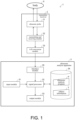
- FIG. 1 is a block diagram of an ultrasonic analysis system 1 according to an embodiment of the present invention.
- the ultrasonic analysis system 1 includes a transmitter /receiver 2 and an ultrasonic analysis apparatus 3 connected to the transmitter/receiver 2.
- the transmitter/receiver 2 is a device for transmitting ultrasonic waves toward muscles inside a body 9 and receiving echo signals reflected from inside the body 9.
- the transmitter/receiver 2 includes an ultrasonic probe 21, a transmitting and receiving module 22, and an A/D conversion module 23.
- the ultrasonic probe 21 is a device for transmitting ultrasonic waves from a plurality of different positions on a surface of the body 9 toward the inside of the body 9 and receiving the ultrasonic waves reflected from the inside of the body 9.
- the ultrasonic probe 21 is configured to be gripped and moved by a user, and an ultrasonic transmission/reception surface is provided on a lower end surface of the ultrasonic probe 21.
- An ultrasonic array sensor constituted by arranging a plurality of ultrasonic vibrators in a line, is arranged on the ultrasonic transmission/reception surface.
- the user When acquiring a tomographic image of the body 9 (or a cross-sectional image), the user makes contact between the body 9 and the ultrasonic transmission/reception surface of the ultrasonic probe 21, and moves the ultrasonic probe 21 along the surface of the body 9 (scans with the ultrasonic probe 21). Meanwhile, the ultrasonic probe 21 intermittently transmits ultrasonic waves from the ultrasonic transmission/reception surface toward the inside of the body 9, and receives the ultrasonic waves reflected from the inside of the body 9 on the ultrasonic transmission/reception surface. Thus, the ultrasonic probe 21 outputs an electric signal (echo signal) indicating the received ultrasonic wave.
- echo signal an electric signal
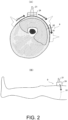
- the ultrasonic probe 21 is attached to a probe adapter 24, and a contacting surface of the probe adapter 24 contacts on the surface of a thigh 91 of the body 9.
- the user moves the ultrasonic probe 21 and the probe adapter 24 along an outer periphery of a transverse section of the thigh 91 that is to be imaged.
- ultrasonic waves are transmitted at predetermined time intervals from the plurality of ultrasonic vibrators of the ultrasonic probe 21.
- the ultrasonic probe 21 transmits ultrasonic waves from different positions toward a quadriceps femoris 92 a plurality of times.
- the ultrasonic probe 21 or the probe adapter 24 may be provided with an inclination sensor.
- the inclination sensor detects an inclination of the ultrasonic probe 21 with respect to a vertical direction, that is, a direction in which the ultrasonic transmission/reception surface is facing.
- the ultrasonic image may be acquired by moving only the ultrasonic probe 21 without using the probe adapter 24.
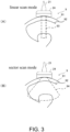
- the ultrasonic probe 21 is operable in two modes, a linear scan mode for acquiring a linear scan image and a sector scan mode for acquiring a sector scan image.
- the ultrasonic analysis apparatus 3 can generate an ultrasonic image in which the zonal region 93 is clearly imaged.
- the ultrasonic analysis apparatus 3 can generate an ultrasonic image obtained by imaging the fan-shaped region 94.
- the ultrasonic probe 21 operates while alternately repeating the linear scan mode and the sector scan mode, and acquires multiple linear scan images and sector scan images, for example, 200 images are acquired during the linear scan mode and the sector scan mode, thus a total of 400 images are acquired.
- the number of the images is only one example, and is set to an arbitrary value. The number may be determined according to the operation and the condition of the subject.
- the ultrasonic probe 21 may be configured to acquire either a linear scan image or a sector scan image at a given time.
- the transmitter/receiver 2 shown in FIG. 1 forms a waveform of a carrier wave that constitutes a frequency of an ultrasonic band into a pulse shape to generate a transmission pulse, and outputs the generated transmission pulse to the ultrasonic probe 21.
- ultrasonic waves are transmitted from the plurality of ultrasonic vibrators of the ultrasonic probe 21 in a depth direction of the body 9.
- the transmitting and receiving module 22 receives the echo signal received by the plurality of ultrasonic vibrators of the ultrasonic probe 21 from the inside of the body 9.
- the A/D conversion module 23 converts the echo signal transmitted from the transmitting and receiving module 22 from an analog format to a digital format, and transmits the converted echo signal to the ultrasonic analysis apparatus 3.
- the ultrasonic analysis apparatus 3 includes an input module 31, a signal processing module 32, and an output module 33.
- the ultrasonic analysis apparatus 3 is constituted by a known personal computer, and includes, as a hardware configuration, a processor (not shown) such as a CPU for performing data processing, a memory (not shown) used by the processor in a work area for data processing, a recording module 34 for recording processing data, a bus (not shown) for transmitting data between each module, and an interface module (hereinafter referred to as I/F module 35) for inputting/outputting data to/from an external apparatus.
- the ultrasonic analysis apparatus 3 can be connected to an external server via a network such as the Internet.
- the input module 31 receives input of an operation from a user.
- the input module 31 may be a keyboard, a mouse, a touch panel, or the like.
- the signal processing module 32 is a functional block that receives an echo signal converted into the digital format from the transmitter/receiver 2 and performs various arithmetic processing functions such as calculation of an index corresponding to a muscle quality of the quadriceps femoris 92 to be analyzed.
- the signal processing module 32 may be implemented in hardware by a logic circuit formed on an integrated circuit, but in this embodiment, the signal processing module 32 is implemented in software by the processor executing an ultrasonic analysis program P previously recorded in the recording module 34 or the memory.
- the ultrasonic analysis program P may be installed in the ultrasonic analysis apparatus 3 via a network.
- the ultrasonic analysis program P may be installed in the ultrasonic analysis apparatus 3 by causing the ultrasonic analysis apparatus 3 to read a computer-readable non-temporary tangible recording medium, such as a CD-ROM, in which the ultrasonic analysis program P is recorded. Details of the signal processing module 32 will be described later with reference to FIG. 4 .
- the output module 33 outputs a calculation result of the signal processing module 32.
- the output module 33 can be configured with a monitor, a printer, or the like.
- the I/F module 35 receives a signal (the converted echo signal) from the transmitter/receiver 2.
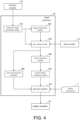
- FIG. 4 is a functional block diagram of the signal processing module 32.
- the signal processing module 32 includes an ultrasonic image generating module 321, an image compositing module 322, an area setting module 323, an index calculation module 324, a muscle quality evaluation module 325, a cross-sectional area calculator 326, and a decision module 327.
- the ultrasonic image generating module 321 generates an ultrasonic image of the inside of the body 9 based on the echo signal input from the I/F module 35.
- the transmitter/receiver 2 transmits ultrasonic waves a plurality of times while alternately repeating the linear scan mode and the sector scan mode, and receives the echo signals reflected from inside the body 9. Therefore, each time the transmitter/receiver 2 receives the echo signal, the I/F module 35 receives the converted echo signal.
- the ultrasonic image generating module 321 generates a linear scan image as an ultrasonic image from the echo signal received in the linear scan mode, and generates a sector scan image as an ultrasonic image from the echo signal received in the sector scan mode.
- the ultrasonic image generating module 321 generates multiple linear scan images and multiple sector scan images, for example, 200 linear scan images and 200 sector scan images, thus, a total of 400 ultrasonic images.
- the ultrasonic image generating module 321 may correct the deformation caused by the pressing of the ultrasonic probe 21 against the cross section of the body 9 in the ultrasonic image, based on a force of the ultrasonic probe 21 pressing the body 9 and a position and direction of the ultrasonic probe 21.
- FIG. 5 is a diagram for explaining generation of a linear scan image.
- FIG. 5A is a partial sectional view of the thigh 91, and the thigh 91 is divided into the quadriceps femoris 92 and other portions for convenience.
- a real image region of the linear scan image also becomes the zonal region 93.
- the linear scan image Li1 as shown in FIG. 5B is generated
- the linear scan image Li2 as shown in FIG. 5C is generated
- the linear scan image Li3 as shown in FIG. 5D is generated.
- FIG. 6 is a diagram for explaining generation of a sector scan image.
- FIG. 6A is a partial sectional view of the thigh 91, and similarly to FIG. 5A , the thigh 91 is divided into the quadriceps femoris 92 and other portions for convenience.
- the ultrasonic wave is directed to the fan-shaped region 94, a real image region in the sector scan image Se is fan-shaped as shown in FIG. 6B .
- the image compositing module 322 stitches a plurality of ultrasonic images (linear scan image and sector scan image) generated by the ultrasonic image generating module 321 to generate a stitched image.
- the method for stitching the ultrasonic image is not particularly limited, and any known method can be used.
- the image compositing module 322 detects and matches a feature amount between regions included in each of the plurality of ultrasonic images, thereby determining a position at which the plurality of ultrasonic images overlap.
- the image compositing module 322 rotates each ultrasonic image on the basis of a detection angle obtained from the inclination sensor, and performs matching on the basis of the rotated ultrasonic image.
- a rotation angle of each ultrasonic image can be accurately corrected, and an overlapped position of a fragment image can be determined with higher accuracy.
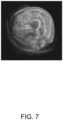
- FIG. 7 is an example of a stitched image of the thigh 91.
- the area setting module 323 shown in FIG. 4 is a functional block for setting a region of interest (ROI: Region of Interest) for at least one of the stitched image and the ultrasonic image.
- ROI Region of Interest
- the area setting module 323 is a functional block that sets a region of interest for the stitched image and sets a region of interest for the ultrasonic image corresponding to the region of interest of the stitched image before the generation of the stitched image.
- the area setting module 323 may set one region of interest for the entire quadriceps femoris 92 included in the stitched image, or may evaluate the muscle qualities of each of a rectus femoris, vastus lateralis, vastus intermedius, and vastus medialis constituting the quadriceps femoris 92 in order to accurately evaluate the muscle qualities of the quadriceps femoris 92. Therefore, in this embodiment, the area setting module 323 sets a region of interest for each of the rectus femoris, vastus lateralis, vastus intermedius, and vastus medialis.
- the area setting module 323 sets the region of interest in the stitched image in response to a user's operation via the input module 31.
- a specific example of setting a region of interest in the stitched image shown in FIG. 7 will be described.
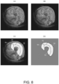
- the user operates the mouse or the like while viewing the stitched image shown in FIG. 7 , and as shown in FIG. 8A , hits a point at the boundary position of the rectus femoris, vastus lateralis, vastus intermedius, and vastus medialis.
- a color of the point may be different depending on a type of the adjacent tissue.
- the points shown in FIG. 8A may be automatically set by a method for automatically detecting the boundaries of the rectus femoris, vastus lateralis, vastus intermedius, and vastus medialis.
- the quadriceps femoris 92 is divided into 4 regions such as the rectus femoris, the vastus lateralis, the vastus intermedius, and the vastus medialis, and the area setting module 323 sets 4 regions as regions of interest R1 to R4, respectively.
- the area setting module 323 extracts a mask image (masked image) comprising the set regions of interest R1 to R4 from the stitched image. As described above, setting of the region of interest for the stitched image is completed.
- the regions of interest R1 to R4 are divided by hatching, a type of hatching is independent of brightness, which will be described later.
- the area setting module 323 sets a region of interest corresponding to the region of interest of the stitched image also for the ultrasonic image before the stitch.
- the area setting module 323 overlaps the mask images composed of the regions of interest R1 to R4 extracted from the stitched image with the ultrasonic images. At this time, the mask image is rotated according to the rotation angle of each ultrasonic image.
- the area setting module 323 can specify the boundary of the region of interest in each ultrasonic image and also set the region of interest for each ultrasonic image.
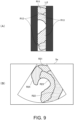
- the regions of interest R11, R12 and R13 included in the linear scan image Li3 are set as shown in FIG. 9A .
- regions of interest R21, R22, R23 and R24 included in the sector scan image Se are set as shown in FIG. 9B .
- region of interest (For example, regions of interest R11 to R13 and R21 to R24) set in the ultrasonic image before synthesis is sometimes referred to as "secondary region of interest”.
- the index calculation module 324 shown in FIG. 4 calculates an index related to the muscle from the secondary region(s) of interest set for the ultrasonic images before the stitch.
- the index calculation module 324 calculates an index corresponding to the muscle quality of the muscle based on the image (here, it is an ultrasonic image, more specifically, a linear scan image or a sector scan image) corresponding to the secondary region of interest set for the ultrasonic image before synthesis. Since the brightness of the image of the muscle increases as the intramuscular fat content increases, the index calculation module 324 calculates the average value of the brightness of the secondary region of interest of the ultrasonic image as an index. A specific example of the calculation method of the index is described below.
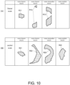
- the index calculation module 324 extracts the secondary region of interest set in each ultrasonic image. For example, from the linear scan image Li3 shown in FIG. 5D , secondary regions of interest R11, R12, and R13 corresponding to the rectus femoris, vastus lateralis, and vastus intermedius, respectively, are extracted as shown in FIG. 10 (A) . Further, from the sector scan image Se shown in FIG. 6B , secondary regions of interest R21, R22, R23, and R24 corresponding to the rectus femoris, vastus lateralis, vastus intermedius, and vastus medialis, respectively, are extracted as shown in FIG. 10 (B) . The index calculation module 324 performs the extraction process for all the linear scan images and the sector scan images.
- an outer peripheral edge of the region of interest may be removed (For example, a few pixels) for extraction.
- line enhancement image filters, binarization, and high brightness line detection by the Dijkstra's algorithm can be used.
- FIGs. 11 (A) and (B) are graphs showing the brightness of the secondary regions of interest R11 to R13 extracted from the 200 linear scan images
- FIGS. 11 (C) and (D) are graphs showing the brightness of the secondary region of interests R21 to R24 extracted from the 200 sector scan images.
- the horizontal axis represents a number assigned to the acquisition order of the linear scan image or the sector scan image
- the vertical axis represents the brightness of the secondary region of interest.
- a portion where the brightness is 70% or more of the maximum brightness of the secondary region of interest is indicated by a thick line.
- the index calculation module 324 calculates an average value of brightness indicated by a thick line for each secondary region of interest, and outputs the calculated average value as an index corresponding to the muscle quality. In calculating the index, all the secondary regions of interest may be used, but the index may be calculated by selectively using either the linear scan image or the sector scan image depending on the part of the muscle.
- the linear scan images and sector scan images have the following advantages and disadvantages.
- the linear scan image has the advantage of being less influenced by the characteristics of the echo and having high reliability.
- the linear scan image has the following disadvantages. Since the observation range at a given time is narrow and each secondary region of interest is only partially reflected, the linear scan image is easily affected by unevenness in the secondary region of interest. It is difficult to distinguish an image having a correct value from an image to be removed due to unevenness. In particular, the latter disadvantage is prominent in a linear scan image of the vastus medialis. In addition, the vastus medialis muscle has a smaller variation range than other muscles (with low sensitivity), and the effect of the directionality to which ultrasonic waves hit is greater.
- the sector scan image has the following advantages. Since an observation range at a given time is wide and many images include all or most part of the secondary region of interest, the sector scan image is averaged even if there is unevenness in the secondary region of interest. It is easy to distinguish an image having a correct value from an image having an abnormal value (when the secondary region of interest is not reflected behind the bone).
- the vastus medialis muscle which shows a large change in the linear scan image, shows the same change as other muscles in the sector scan image.
- the sector scan image is easily affected by the characteristics of the echo, and has a disadvantage that the deeper the sector scan image is, the worse the echo characteristics become.
- an image for calculating the index may be selected for each muscle region.
- the correlation between the brightness of the secondary region of interest and the equivalent CT value tends to be higher in the linear scan image than in the sector scan image. Therefore, for the vastus lateralis and vastus intermedius, an index may be calculated using the linear scan image.
- the correlation between the brightness of the secondary region of interest and the CT value equivalent tends to be higher in the sector scan image than in the linear scan image. Therefore, for the rectus femoris and vastus medialis, an index may be calculated using the sector scan image.
- the brightness can be expressed in 0 ⁇ 255 gradations.
- a brightness correction technique may be used to calculate a corrected brightness.
- the calculation of the corrected brightness is possible by a) correcting for scaling according to the part in order to evaluate a tendency of the part that is bright and the part that is dark appears in the same order, and b) correcting for differences of trends when using a mix of results from different scanning methods.
- it is not necessary to standardize settings related to image quality and brightness such as a gain of the transmitter/receiver 2.
- the brightness is an image processing value under a specific condition, it can be generalized by converting it into a physical index.
- brightness can be converted to dB as an echo reflection level.
- a reference can be determined by a substance corresponding to 0 dB (For example, a phantom for quality control), and the brightness can be converted to dB from measurement or calculation. This makes it possible to correct variations in mass production through inspection and correction, and to standardize indices for multiple models.
- the index calculation module 324 may calculate a CT value equivalent value (HU), an MRI equivalent value (T1, T2), or a muscle tissue evaluation value (Fat equivalent (%), effective muscle cross-sectional area, etc.) of the image as an index corresponding to the muscle quality, instead of the average value of the brightness.
- HU CT value equivalent value
- T1, T2 MRI equivalent value
- Fat equivalent (%), effective muscle cross-sectional area, etc. a muscle tissue evaluation value
- These values can be correlated with clinically significant data, such as CT and MRI measurements and the actual anatomic and medical condition of the muscle.
- the muscle quality evaluation module 325 shown in FIG. 4 evaluates the muscle quality based on the index calculated by the index calculation module 324.
- the index is an average value of brightness, it can be evaluated that the larger the average value is, the larger the amount of fat in the muscle and lower is the muscle quality.
- a histogram representing the brightness distribution can also be used to evaluate the muscle quality. For example, as shown in FIGs. 12 (A) and 12 (B) , since a ratio of the number of pixels to a specific brightness value is different between the elderly and the young, the muscle quality can be evaluated based on the ratio.
- the muscle quality can be evaluated by a size relationship of the region of the brightness distribution. Since the brightness distribution differs as the muscle quality decreases from the healthy state, for example, as shown in FIG. 13 , the brightness values in the gray area and the areas before and after the gray area are judged in 3 stages of ⁇ (abound), ⁇ (intermediate), and ⁇ (little), and the muscle quality is evaluated by the combination of the size relation.
- the vertical axis and the horizontal axis represent brightness and image number, respectively.
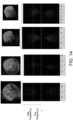
- patterns and spatial frequencies can be used to evaluate muscle quality.
- a two-dimensional fast Fourier transform FFT: Fast Fourier Transform
- the upper four images shown in FIG. 14 are images before conversion, and the lower four images are images after conversion.
- a high frequency component of the brightness in the converted image is larger than a low frequency component, and the low frequency component is at a low level, but the distribution of the brightness moves to the low frequency side with the lowering of the muscle quality. Therefore, the muscle quality can be evaluated based on the high frequency component and the low frequency component.
- this evaluation method can improve the evaluation accuracy by additionally performing the above-mentioned muscle quality evaluation using the average value or histogram of brightness.
- the cross-sectional area calculator 326 shown in FIG. 4 calculates the cross-sectional areas of the rectus femoris, vastus lateralis, vastus intermedius, and vastus medialis of the quadriceps femoris 92.
- the calculation result is an input to the muscle quality evaluation module 325 together with the evaluation result of the decision module 327.
- the decision module 327 also receives subject information T such as the age, sex, height, and weight of the body 9 stored in the recording module 34.
- the cross-sectional area calculator 326 and the subject information T may have any configuration.
- the decision module 327 presents the evaluation result of the muscle quality, the muscle cross-sectional area, and reference data based on the subject information T inputted from the muscle quality evaluation module 325 and the cross-sectional area calculator 326, respectively. Further, the decision module 327 performs calculation (e.g., T-SCORE) in comparison with the reference data for determination. These results are output to the output module 33 and can be confirmed by the user.
- calculation e.g., T-SCORE
- FIG. 15 is a flow chart showing a flow of processing in an ultrasonic analysis method according to the present embodiment.
- the ultrasonic analysis method according to the present embodiment can be implemented by the transmitter/receiver 2 and the ultrasonic analysis apparatus 3.
- step S1 the transmitter/receiver 2 shown in FIG. 1 transmits ultrasonic waves from different positions from the transducer of the ultrasonic probe 21 toward the muscles inside of the body 9, and receives the echo signals reflected from inside of the body 9 by the transducer of the ultrasonic probe 21.
- the muscle is the quadriceps femoris 92.
- the transmitter/receiver 2 digitally converts the received echo signal and transmits it to the ultrasonic analysis apparatus 3, and the I/F module 35 of the ultrasonic analysis apparatus 3 receives the echo signal from the transmitter/receiver 2.
- step S2 the ultrasonic image generating module 321 shown in FIG. 4 generates an ultrasonic image of the inside of the body 9 based on the received echo signal.
- the ultrasonic image generating module 321 generates a linear scan image and a sector scan image as ultrasonic images.
- step S3 the image compositing module 322 stitches the ultrasonic images to generate a stitched image.
- step S4 the area setting module 323 sets a region of interest for the stitched image and the ultrasonic image before the stitching.
- a region of interest is set for each of the rectus femoris, vastus lateralis, vastus intermedius, and vastus medialis constituting the quadriceps femoris 92.
- step S5 the index calculation module 324 calculates an index corresponding to the muscle quality based on the image corresponding to the secondary region of interest set for the ultrasonic image before the stitching.
- the index is, for example, an average value of brightness of an image.
- step S6 the muscle quality evaluation module 325 evaluates the muscle quality based on the index.
- the evaluation of the muscle quality can be performed based on the average value of the brightness, the histogram of the brightness, the ratio of the number of pixels of a specific brightness value, etc.
- the cross-sectional area calculating module 326 calculates a muscle cross-sectional area.
- the cross-sectional area calculation module 326 calculates the cross-sectional areas of the rectus femoris, vastus lateralis, vastus intermedius, and vastus medialis of the quadriceps femoris 92.
- step S7 the decision module 327 presents the evaluation result of the muscle quality, the muscle cross-sectional area, and reference data based on the subject information T.
- the ultrasonic analysis apparatus 3 and the ultrasonic analysis method according to the present embodiment it is possible to evaluate the muscle quality by analyzing an ultrasonic image without using a CT apparatus or an MRI apparatus having a complicated configuration as in the prior art. Therefore, it is possible to evaluate the muscle quality with a relatively simple constitution without accompanying exposure to possibly harmful radiations.
- the index calculation module 324 calculates the index corresponding to the muscle quality from the secondary region of interest set for the ultrasonic image before synthesis, in accordance with the invention but the index could have been calculated from the region of interest set for the stitched image in an example outside the scope of the present invention.
- the brightness decreases according to the depth in the ultrasonic image, and thus, the brightness is affected in the stitched image. Therefore, in accordance with the invention, the index is calculated from the secondary region of interest set for the ultrasonic image before synthesis.
- a plurality of ultrasonic images are acquired by transmitting ultrasonic waves from different positions toward the quadriceps femoris 92 a plurality of times, but the method for acquiring the plurality of ultrasonic images is not limited thereto.
- a plurality of ultrasonic probes similar to the ultrasonic probe 21, may be disposed around the thigh 91, and ultrasonic waves may be simultaneously transmitted from each ultrasonic probe toward the quadriceps femoris 92 to obtain the plurality of ultrasonic images.
- the ultrasonic image generating module 321 may generate the linear scan image and the sector scan image as ultrasonic images in the aforementioned embodiment, the ultrasonic image generating module 321 may generate only one of the linear scan image and the sector scan image in various other embodiments.
- the ultrasonic image generating module 321 may generate a convex image as an ultrasonic image.
- the region of interest may be set in the convex image, and the index corresponding to the muscle quality may be calculated from the image corresponding to the region of interest.
- 200 linear scan images and 200 sector scan images are used for calculating the index respectively, but the number of ultrasonic images used for calculating the index is not particularly limited, and a part of the acquired ultrasonic images may be selected and used for calculating the index. For example, 50 images may be selected at predetermined intervals from the total 400 ultrasonic images arranged in an order of acquisition.
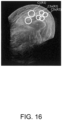
- the quadriceps femoris 92 is divided into four regions of the rectus femoris, vastus lateralis, vastus intermedius, and vastus medialis, but it may be difficult to manually find the boundary of the region depending on the subject. Therefore, for example, as shown in FIG. 16 , a typical position of the muscle may be surrounded by a frame having a simple shape such as a circular frame, and an area within the frame may be set as a region of interest. In the example shown in FIG. 16 , a circular frame C1 including the rectus femoris is set as a region of interest R1.
- a region within the muscle may be surrounded by a plurality of circular frames C2a and C2b, and a region within the circular frames C2a and C2b may be set as a region of interest R2.
- one region of interest may be set for the entire quadriceps femoris 92, or at least one of the rectus femoris, vastus lateralis, vastus intermedius, and vastus medialis constituting the quadriceps femoris 92.
- the analysis subject of the muscle is the quadriceps femoris 92, but the present invention is not limited thereto, and any muscle such as the back of the thigh 91, the calf, and the upper arm muscle can be included in the analysis subject.
- the ultrasonic wave is intermittently transmitted from the ultrasonic probe 21 while the ultrasonic probe 21 is moved along the surface of the body 9, the embodiments for obtaining ultrasound images are not limited thereto.
- a plurality of ultrasonic probes 21 may be arranged in the body 9, and ultrasonic waves may be transmitted simultaneously from each ultrasonic probe 21.
Landscapes
- Health & Medical Sciences (AREA)
- Life Sciences & Earth Sciences (AREA)
- Engineering & Computer Science (AREA)
- Physics & Mathematics (AREA)
- Heart & Thoracic Surgery (AREA)
- Surgery (AREA)
- Nuclear Medicine, Radiotherapy & Molecular Imaging (AREA)
- Pathology (AREA)
- Radiology & Medical Imaging (AREA)
- Biomedical Technology (AREA)
- Veterinary Medicine (AREA)
- Medical Informatics (AREA)
- Molecular Biology (AREA)
- Biophysics (AREA)
- Animal Behavior & Ethology (AREA)
- General Health & Medical Sciences (AREA)
- Public Health (AREA)
- Computer Vision & Pattern Recognition (AREA)
- Physiology (AREA)
- Acoustics & Sound (AREA)
- Ultra Sonic Daignosis Equipment (AREA)
Claims (9)
- Appareil d'analyse ultrasonore (3), comprenant :un module d'interface (35) configuré pour recevoir des signaux en provenance d'un émetteur/récepteur (2) qui reçoit des ondes ultrasonores émises à partir d'une pluralité de positions mutuellement différentes sur une surface d'un corps (9) vers un muscle à l'intérieur du corps (9) et réfléchies depuis l'intérieur du corps (9) ;un module de génération d'images ultrasonores (321) configuré pour générer une pluralité d'images ultrasonores correspondant aux positions respectives sur la base des signaux entrés en provenance du module d'interface (35) ;un module de composition d'images (322) configuré pour assembler la pluralité d'images ultrasonores aux positions respectives pour générer une image assemblée ;un module de définition de zone (323) configuré pour définir à la fois une région d'intérêt pour l'image assemblée et unerégion d'intérêt secondaire pour au moins une image ultrasonore de la pluralité d'images ultrasonores avant l'assemblage, la région d'intérêt définie pour l'image assemblée et chaque région d'intérêt secondaire définie pour l'au moins une image ultrasonore avant l'assemblage correspondant l'une à l'autre ; etun module de calcul d'indice (324) configuré pour calculer un indice se rapportant au muscle, l'indice correspondant à une qualité musculaire du muscle, à partir de la ou des région(s) d'intérêt secondaire(s) définie(s) pour l'au moins une image ultrasonore avant l'assemblage.
- Appareil d'analyse ultrasonore (3) selon la revendication 1, dans lequel :
la pluralité d'images ultrasonores comportent au moins l'une parmi une image de balayage linéaire et une image de balayage sectoriel. - Appareil d'analyse ultrasonore (3) selon l'une des revendications 1 à 2, dans lequel :
l'indice est une valeur moyenne d'une luminosité de la ou des région(s) d'intérêt secondaire(s). - Appareil d'analyse ultrasonore (3) selon l'une des revendications 1 à 3, dans lequel :
le muscle est un muscle quadriceps fémoral (92). - Appareil d'analyse ultrasonore (3) selon la revendication 4, dans lequel :le module de définition de zone (323) définit la région d'intérêt et une ou des région(s) d'intérêt secondaire(s) pour chacun parmi un muscle droit fémoral, un muscle vaste latéral, un muscle vaste intermédiaire et un muscle vaste médial du muscle quadriceps fémoral (92), etle module de calcul d'indice (324) calcule l'indice se rapportant à chaque muscle parmi le muscle droit fémoral, le muscle vaste latéral, le muscle vaste intermédiaire et le muscle vaste médial.
- Appareil d'analyse ultrasonore (3) selon la revendication 5, dans lequel :la pluralité d'images ultrasonores comportent une image de balayage sectoriel et une image de balayage linéaire, etle module de calcul d'indice (324) calcule l'indice se rapportant à chaque muscle parmi le muscle vaste latéral et le muscle vaste intermédiaire à partir de la ou des région(s) d'intérêt secondaire(s) définie(s) dans l'image de balayage linéaire, et calcule l'indice se rapportant à chaque muscle parmi le muscle droit fémoral et le muscle vaste médial à partir de la ou des région(s) d'intérêt secondaire(s) définie(s) dans l'image de balayage sectoriel.
- Appareil d'analyse ultrasonore (3) selon l'une des revendications 1 à 6, dans lequel :
le module de définition de zone (323) extrait une image de masque comprenant la région d'intérêt définie dans l'image assemblée à partir de l'image assemblée et définit la région d'intérêt secondaire pour l'au moins une image ultrasonore avant l'assemblage par la superposition de l'image de masque sur l'image ultrasonore. - Procédé d'analyse ultrasonore, comprenant les étapes de :la réception de signaux en provenance d'un émetteur/récepteur (2) qui reçoit des ondes ultrasonores émises à partir d'une pluralité de positions mutuellement différentes sur une surface d'un corps (9) vers un muscle à l'intérieur du corps (9) et réfléchies depuis l'intérieur du corps (9) ;la génération d'une pluralité d'images ultrasonores correspondant aux positions respectives sur la base des signaux reçus ;l'assemblage de la pluralité d'images ultrasonores aux positions respectives pour générer une image assemblée ;la définition à la fois d'une région d'intérêt pour l'image assemblée et d'une région d'intérêt secondaire pour au moins une image ultrasonore de la pluralité d'images ultrasonores avant l'assemblage, la région d'intérêt définie pour l'image assemblée et chaque région d'intérêt secondaire définie pour l'au moins une image ultrasonore avant l'assemblage correspondant l'une à l'autre ; etle calcul d'un indice se rapportant au muscle, l'indice correspondant à une qualité musculaire du muscle, à partir de la ou des région(s) d'intérêt secondaire(s) définie(s) pour l'au moins une image ultrasonore avant l'assemblage.
- Programme d'analyse ultrasonore configuré pour amener un ordinateur à exécuter un traitement, l'ordinateur commandant un appareil d'analyse ultrasonore selon l'une des revendications 1 à 7, lequel programme comprend des instructions, qui lors de leur lancement sur l'ordinateur, amènent l'appareil d'analyse ultrasonore à mettre en œuvre le procédé selon la revendication 8.
Applications Claiming Priority (2)
| Application Number | Priority Date | Filing Date | Title |
|---|---|---|---|
| JP2018155356 | 2018-08-22 | ||
| PCT/JP2019/027884 WO2020039796A1 (fr) | 2018-08-22 | 2019-07-16 | Dispositif d'analyse ultrasonore, procédé d'analyse ultrasonore et programme d'analyse ultrasonore |
Publications (3)
| Publication Number | Publication Date |
|---|---|
| EP3841983A1 EP3841983A1 (fr) | 2021-06-30 |
| EP3841983A4 EP3841983A4 (fr) | 2022-05-18 |
| EP3841983B1 true EP3841983B1 (fr) | 2024-01-10 |
Family
ID=69592509
Family Applications (1)
| Application Number | Title | Priority Date | Filing Date |
|---|---|---|---|
| EP19850967.1A Active EP3841983B1 (fr) | 2018-08-22 | 2019-07-16 | Dispositif d'analyse ultrasonore, procédé d'analyse ultrasonore et programme d'analyse ultrasonore |
Country Status (5)
| Country | Link |
|---|---|
| US (1) | US20210169454A1 (fr) |
| EP (1) | EP3841983B1 (fr) |
| JP (1) | JP7179860B2 (fr) |
| CN (1) | CN112367922B (fr) |
| WO (1) | WO2020039796A1 (fr) |
Families Citing this family (4)
| Publication number | Priority date | Publication date | Assignee | Title |
|---|---|---|---|---|
| CN117119968A (zh) * | 2021-05-11 | 2023-11-24 | 古野电气株式会社 | 超声波拍摄装置、超声波拍摄方法、超声波拍摄系统及超声波拍摄程序 |
| CN118265489A (zh) * | 2021-11-19 | 2024-06-28 | 古野电气株式会社 | 超声波拍摄装置、超声波拍摄系统、超声波拍摄方法、以及超声波拍摄程序 |
| TWI797976B (zh) * | 2022-01-26 | 2023-04-01 | 國立成功大學 | 測量肌肉量的方法 |
| CN116977184B (zh) * | 2023-08-01 | 2024-03-19 | 南方电网数字电网研究院股份有限公司 | 输电线路图像获取方法、装置、计算机设备和存储介质 |
Family Cites Families (12)
| Publication number | Priority date | Publication date | Assignee | Title |
|---|---|---|---|---|
| CN100393283C (zh) * | 2002-09-12 | 2008-06-11 | 株式会社日立医药 | 生物体组织动状态跟踪方法、使用该方法的图像诊断装置 |
| US7092749B2 (en) * | 2003-06-11 | 2006-08-15 | Siemens Medical Solutions Usa, Inc. | System and method for adapting the behavior of a diagnostic medical ultrasound system based on anatomic features present in ultrasound images |
| JP2009247739A (ja) * | 2008-04-09 | 2009-10-29 | Toshiba Corp | 医用画像処理表示装置、そのコンピュータ処理プログラム及び超音波診断装置。 |
| JP5596393B2 (ja) * | 2010-03-31 | 2014-09-24 | 古野電気株式会社 | 画素データ生成装置、画像表示装置、レーダ装置、画素データ生成方法及び画素データ生成プログラム |
| CN102324094A (zh) * | 2011-05-30 | 2012-01-18 | 复旦大学 | 骨骼肌损伤超声图像纹理定量分析的强度界面多级分解法 |
| US9179890B2 (en) * | 2011-07-14 | 2015-11-10 | Siemens Aktiengesellschaft | Model-based positioning for intracardiac echocardiography volume stitching |
| JP2014188149A (ja) * | 2013-03-27 | 2014-10-06 | Seiko Epson Corp | 超音波測定装置、超音波画像装置及び超音波測定方法 |
| KR101797042B1 (ko) * | 2015-05-15 | 2017-11-13 | 삼성전자주식회사 | 의료 영상 합성 방법 및 장치 |
| CN107835663B (zh) * | 2015-07-13 | 2022-02-08 | 古野电气株式会社 | 探头附加器、超声波摄像装置、超声波摄像方法及存储介质 |
| CN106264573B (zh) * | 2016-07-26 | 2019-03-22 | 吉林大学 | 便携式肌肉力学参数及肌肉力在体超声检测装置及方法 |
| CN110022774B (zh) * | 2016-11-29 | 2022-08-30 | 皇家飞利浦有限公司 | 超声成像系统和方法 |
| US11064971B2 (en) * | 2016-11-30 | 2021-07-20 | Musclesound, Inc. | Non-Invasive determination of muscle tissue quality and intramuscular fat |
-
2019
- 2019-07-16 CN CN201980045489.5A patent/CN112367922B/zh active Active
- 2019-07-16 EP EP19850967.1A patent/EP3841983B1/fr active Active
- 2019-07-16 WO PCT/JP2019/027884 patent/WO2020039796A1/fr not_active Ceased
- 2019-07-16 JP JP2020538231A patent/JP7179860B2/ja active Active
-
2021
- 2021-02-22 US US17/182,103 patent/US20210169454A1/en not_active Abandoned
Also Published As
| Publication number | Publication date |
|---|---|
| CN112367922A (zh) | 2021-02-12 |
| US20210169454A1 (en) | 2021-06-10 |
| JPWO2020039796A1 (ja) | 2021-08-12 |
| EP3841983A1 (fr) | 2021-06-30 |
| WO2020039796A1 (fr) | 2020-02-27 |
| CN112367922B (zh) | 2024-09-17 |
| JP7179860B2 (ja) | 2022-11-29 |
| EP3841983A4 (fr) | 2022-05-18 |
Similar Documents
| Publication | Publication Date | Title |
|---|---|---|
| EP3841983B1 (fr) | Dispositif d'analyse ultrasonore, procédé d'analyse ultrasonore et programme d'analyse ultrasonore | |
| JP5730979B2 (ja) | 超音波診断装置、及び弾性評価方法 | |
| US10743845B2 (en) | Ultrasound diagnostic apparatus and method for distinguishing a low signal/noise area in an ultrasound image | |
| US7985182B2 (en) | Ultrasonic diagnostic apparatus and ultrasonic image acquiring method | |
| JP6216736B2 (ja) | 超音波診断装置、及び超音波診断方法 | |
| US20130046168A1 (en) | Method and system of characterization of carotid plaque | |
| US20100249590A1 (en) | Ultrasonic diagnosis apparatus and ultrasonic image generating method | |
| US20100014738A1 (en) | Method and system for breast cancer screening | |
| JP5192921B2 (ja) | 超音波診断装置 | |
| US20100256493A1 (en) | Ultrasonic diagostic apparatus, operation method thereof, and ultrasonic diagnostic program | |
| US20120065512A1 (en) | Ultrasonic diagnostic apparatus and ultrasonic image processng apparatus | |
| US20050129297A1 (en) | Classification of breast lesion method and system | |
| JP5235103B2 (ja) | 超音波診断装置 | |
| US20050283076A1 (en) | Non-invasive diagnosis of breast cancer using real-time ultrasound strain imaging | |
| US20020178833A1 (en) | Method and system for improving the spatial resolution for strain imaging | |
| CN109069117B (zh) | 超声波诊断装置 | |
| JP7712189B2 (ja) | 超音波画像分析装置、超音波診断装置および超音波画像分析装置の制御方法 | |
| US8083679B1 (en) | Ultrasonic imaging apparatus | |
| CN113491535B (zh) | 超声波诊断装置、信号处理装置以及记录介质 | |
| JP4217542B2 (ja) | 超音波診断装置 | |
| JP7187734B1 (ja) | 画像処理装置及びプログラム | |
| JP7238164B2 (ja) | 超音波観測装置、超音波観測システム、超音波観測方法、超音波観測プログラム、及び超音波内視鏡システム | |
| WO2024203331A1 (fr) | Dispositif de diagnostic par ultrasons et procédé de commande pour dispositif de diagnostic par ultrasons | |
| CN121667753A (zh) | 超声波诊断装置、衰减图生成方法及程序产品 | |
| CN120514420A (zh) | 一种用于超声膈肌的自动测量方法、计算机设备及介质 |
Legal Events
| Date | Code | Title | Description |
|---|---|---|---|
| STAA | Information on the status of an ep patent application or granted ep patent |
Free format text: STATUS: THE INTERNATIONAL PUBLICATION HAS BEEN MADE |
|
| PUAI | Public reference made under article 153(3) epc to a published international application that has entered the european phase |
Free format text: ORIGINAL CODE: 0009012 |
|
| STAA | Information on the status of an ep patent application or granted ep patent |
Free format text: STATUS: REQUEST FOR EXAMINATION WAS MADE |
|
| 17P | Request for examination filed |
Effective date: 20210319 |
|
| AK | Designated contracting states |
Kind code of ref document: A1 Designated state(s): AL AT BE BG CH CY CZ DE DK EE ES FI FR GB GR HR HU IE IS IT LI LT LU LV MC MK MT NL NO PL PT RO RS SE SI SK SM TR |
|
| DAV | Request for validation of the european patent (deleted) | ||
| DAX | Request for extension of the european patent (deleted) | ||
| REG | Reference to a national code |
Ref country code: DE Free format text: PREVIOUS MAIN CLASS: A61B0008140000 Ipc: A61B0008000000 Ref country code: DE Ref legal event code: R079 Ref document number: 602019045020 Country of ref document: DE Free format text: PREVIOUS MAIN CLASS: A61B0008140000 Ipc: A61B0008000000 |
|
| A4 | Supplementary search report drawn up and despatched |
Effective date: 20220420 |
|
| RIC1 | Information provided on ipc code assigned before grant |
Ipc: A61B 8/08 20060101ALI20220412BHEP Ipc: A61B 8/14 20060101ALI20220412BHEP Ipc: A61B 8/00 20060101AFI20220412BHEP |
|
| GRAP | Despatch of communication of intention to grant a patent |
Free format text: ORIGINAL CODE: EPIDOSNIGR1 |
|
| STAA | Information on the status of an ep patent application or granted ep patent |
Free format text: STATUS: GRANT OF PATENT IS INTENDED |
|
| INTG | Intention to grant announced |
Effective date: 20230927 |
|
| GRAS | Grant fee paid |
Free format text: ORIGINAL CODE: EPIDOSNIGR3 |
|
| GRAA | (expected) grant |
Free format text: ORIGINAL CODE: 0009210 |
|
| STAA | Information on the status of an ep patent application or granted ep patent |
Free format text: STATUS: THE PATENT HAS BEEN GRANTED |
|
| AK | Designated contracting states |
Kind code of ref document: B1 Designated state(s): AL AT BE BG CH CY CZ DE DK EE ES FI FR GB GR HR HU IE IS IT LI LT LU LV MC MK MT NL NO PL PT RO RS SE SI SK SM TR |
|
| REG | Reference to a national code |
Ref country code: GB Ref legal event code: FG4D |
|
| REG | Reference to a national code |
Ref country code: CH Ref legal event code: EP |
|
| REG | Reference to a national code |
Ref country code: DE Ref legal event code: R096 Ref document number: 602019045020 Country of ref document: DE |
|
| REG | Reference to a national code |
Ref country code: IE Ref legal event code: FG4D |
|
| REG | Reference to a national code |
Ref country code: LT Ref legal event code: MG9D |
|
| REG | Reference to a national code |
Ref country code: NL Ref legal event code: MP Effective date: 20240110 |
|
| REG | Reference to a national code |
Ref country code: AT Ref legal event code: MK05 Ref document number: 1648240 Country of ref document: AT Kind code of ref document: T Effective date: 20240110 |
|
| PG25 | Lapsed in a contracting state [announced via postgrant information from national office to epo] |
Ref country code: NL Free format text: LAPSE BECAUSE OF FAILURE TO SUBMIT A TRANSLATION OF THE DESCRIPTION OR TO PAY THE FEE WITHIN THE PRESCRIBED TIME-LIMIT Effective date: 20240110 |
|
| PG25 | Lapsed in a contracting state [announced via postgrant information from national office to epo] |
Ref country code: NL Free format text: LAPSE BECAUSE OF FAILURE TO SUBMIT A TRANSLATION OF THE DESCRIPTION OR TO PAY THE FEE WITHIN THE PRESCRIBED TIME-LIMIT Effective date: 20240110 |
|
| PG25 | Lapsed in a contracting state [announced via postgrant information from national office to epo] |
Ref country code: IS Free format text: LAPSE BECAUSE OF FAILURE TO SUBMIT A TRANSLATION OF THE DESCRIPTION OR TO PAY THE FEE WITHIN THE PRESCRIBED TIME-LIMIT Effective date: 20240510 |
|
| PG25 | Lapsed in a contracting state [announced via postgrant information from national office to epo] |
Ref country code: LT Free format text: LAPSE BECAUSE OF FAILURE TO SUBMIT A TRANSLATION OF THE DESCRIPTION OR TO PAY THE FEE WITHIN THE PRESCRIBED TIME-LIMIT Effective date: 20240110 |
|
| PG25 | Lapsed in a contracting state [announced via postgrant information from national office to epo] |
Ref country code: GR Free format text: LAPSE BECAUSE OF FAILURE TO SUBMIT A TRANSLATION OF THE DESCRIPTION OR TO PAY THE FEE WITHIN THE PRESCRIBED TIME-LIMIT Effective date: 20240411 |
|
| PG25 | Lapsed in a contracting state [announced via postgrant information from national office to epo] |
Ref country code: HR Free format text: LAPSE BECAUSE OF FAILURE TO SUBMIT A TRANSLATION OF THE DESCRIPTION OR TO PAY THE FEE WITHIN THE PRESCRIBED TIME-LIMIT Effective date: 20240110 Ref country code: RS Free format text: LAPSE BECAUSE OF FAILURE TO SUBMIT A TRANSLATION OF THE DESCRIPTION OR TO PAY THE FEE WITHIN THE PRESCRIBED TIME-LIMIT Effective date: 20240410 |
|
| PG25 | Lapsed in a contracting state [announced via postgrant information from national office to epo] |
Ref country code: ES Free format text: LAPSE BECAUSE OF FAILURE TO SUBMIT A TRANSLATION OF THE DESCRIPTION OR TO PAY THE FEE WITHIN THE PRESCRIBED TIME-LIMIT Effective date: 20240110 |
|
| PG25 | Lapsed in a contracting state [announced via postgrant information from national office to epo] |
Ref country code: AT Free format text: LAPSE BECAUSE OF FAILURE TO SUBMIT A TRANSLATION OF THE DESCRIPTION OR TO PAY THE FEE WITHIN THE PRESCRIBED TIME-LIMIT Effective date: 20240110 |
|
| PG25 | Lapsed in a contracting state [announced via postgrant information from national office to epo] |
Ref country code: RS Free format text: LAPSE BECAUSE OF FAILURE TO SUBMIT A TRANSLATION OF THE DESCRIPTION OR TO PAY THE FEE WITHIN THE PRESCRIBED TIME-LIMIT Effective date: 20240410 Ref country code: NO Free format text: LAPSE BECAUSE OF FAILURE TO SUBMIT A TRANSLATION OF THE DESCRIPTION OR TO PAY THE FEE WITHIN THE PRESCRIBED TIME-LIMIT Effective date: 20240410 Ref country code: LT Free format text: LAPSE BECAUSE OF FAILURE TO SUBMIT A TRANSLATION OF THE DESCRIPTION OR TO PAY THE FEE WITHIN THE PRESCRIBED TIME-LIMIT Effective date: 20240110 Ref country code: IS Free format text: LAPSE BECAUSE OF FAILURE TO SUBMIT A TRANSLATION OF THE DESCRIPTION OR TO PAY THE FEE WITHIN THE PRESCRIBED TIME-LIMIT Effective date: 20240510 Ref country code: HR Free format text: LAPSE BECAUSE OF FAILURE TO SUBMIT A TRANSLATION OF THE DESCRIPTION OR TO PAY THE FEE WITHIN THE PRESCRIBED TIME-LIMIT Effective date: 20240110 Ref country code: GR Free format text: LAPSE BECAUSE OF FAILURE TO SUBMIT A TRANSLATION OF THE DESCRIPTION OR TO PAY THE FEE WITHIN THE PRESCRIBED TIME-LIMIT Effective date: 20240411 Ref country code: ES Free format text: LAPSE BECAUSE OF FAILURE TO SUBMIT A TRANSLATION OF THE DESCRIPTION OR TO PAY THE FEE WITHIN THE PRESCRIBED TIME-LIMIT Effective date: 20240110 Ref country code: BG Free format text: LAPSE BECAUSE OF FAILURE TO SUBMIT A TRANSLATION OF THE DESCRIPTION OR TO PAY THE FEE WITHIN THE PRESCRIBED TIME-LIMIT Effective date: 20240110 Ref country code: AT Free format text: LAPSE BECAUSE OF FAILURE TO SUBMIT A TRANSLATION OF THE DESCRIPTION OR TO PAY THE FEE WITHIN THE PRESCRIBED TIME-LIMIT Effective date: 20240110 |
|
| PG25 | Lapsed in a contracting state [announced via postgrant information from national office to epo] |
Ref country code: PT Free format text: LAPSE BECAUSE OF FAILURE TO SUBMIT A TRANSLATION OF THE DESCRIPTION OR TO PAY THE FEE WITHIN THE PRESCRIBED TIME-LIMIT Effective date: 20240510 Ref country code: PL Free format text: LAPSE BECAUSE OF FAILURE TO SUBMIT A TRANSLATION OF THE DESCRIPTION OR TO PAY THE FEE WITHIN THE PRESCRIBED TIME-LIMIT Effective date: 20240110 |
|
| PG25 | Lapsed in a contracting state [announced via postgrant information from national office to epo] |
Ref country code: SE Free format text: LAPSE BECAUSE OF FAILURE TO SUBMIT A TRANSLATION OF THE DESCRIPTION OR TO PAY THE FEE WITHIN THE PRESCRIBED TIME-LIMIT Effective date: 20240110 Ref country code: PT Free format text: LAPSE BECAUSE OF FAILURE TO SUBMIT A TRANSLATION OF THE DESCRIPTION OR TO PAY THE FEE WITHIN THE PRESCRIBED TIME-LIMIT Effective date: 20240510 Ref country code: PL Free format text: LAPSE BECAUSE OF FAILURE TO SUBMIT A TRANSLATION OF THE DESCRIPTION OR TO PAY THE FEE WITHIN THE PRESCRIBED TIME-LIMIT Effective date: 20240110 Ref country code: LV Free format text: LAPSE BECAUSE OF FAILURE TO SUBMIT A TRANSLATION OF THE DESCRIPTION OR TO PAY THE FEE WITHIN THE PRESCRIBED TIME-LIMIT Effective date: 20240110 |
|
| PG25 | Lapsed in a contracting state [announced via postgrant information from national office to epo] |
Ref country code: DK Free format text: LAPSE BECAUSE OF FAILURE TO SUBMIT A TRANSLATION OF THE DESCRIPTION OR TO PAY THE FEE WITHIN THE PRESCRIBED TIME-LIMIT Effective date: 20240110 |
|
| REG | Reference to a national code |
Ref country code: DE Ref legal event code: R097 Ref document number: 602019045020 Country of ref document: DE |
|
| PG25 | Lapsed in a contracting state [announced via postgrant information from national office to epo] |
Ref country code: SM Free format text: LAPSE BECAUSE OF FAILURE TO SUBMIT A TRANSLATION OF THE DESCRIPTION OR TO PAY THE FEE WITHIN THE PRESCRIBED TIME-LIMIT Effective date: 20240110 |
|
| PG25 | Lapsed in a contracting state [announced via postgrant information from national office to epo] |
Ref country code: CZ Free format text: LAPSE BECAUSE OF FAILURE TO SUBMIT A TRANSLATION OF THE DESCRIPTION OR TO PAY THE FEE WITHIN THE PRESCRIBED TIME-LIMIT Effective date: 20240110 Ref country code: EE Free format text: LAPSE BECAUSE OF FAILURE TO SUBMIT A TRANSLATION OF THE DESCRIPTION OR TO PAY THE FEE WITHIN THE PRESCRIBED TIME-LIMIT Effective date: 20240110 |
|
| PG25 | Lapsed in a contracting state [announced via postgrant information from national office to epo] |
Ref country code: SK Free format text: LAPSE BECAUSE OF FAILURE TO SUBMIT A TRANSLATION OF THE DESCRIPTION OR TO PAY THE FEE WITHIN THE PRESCRIBED TIME-LIMIT Effective date: 20240110 |
|
| PG25 | Lapsed in a contracting state [announced via postgrant information from national office to epo] |
Ref country code: SM Free format text: LAPSE BECAUSE OF FAILURE TO SUBMIT A TRANSLATION OF THE DESCRIPTION OR TO PAY THE FEE WITHIN THE PRESCRIBED TIME-LIMIT Effective date: 20240110 Ref country code: SK Free format text: LAPSE BECAUSE OF FAILURE TO SUBMIT A TRANSLATION OF THE DESCRIPTION OR TO PAY THE FEE WITHIN THE PRESCRIBED TIME-LIMIT Effective date: 20240110 Ref country code: RO Free format text: LAPSE BECAUSE OF FAILURE TO SUBMIT A TRANSLATION OF THE DESCRIPTION OR TO PAY THE FEE WITHIN THE PRESCRIBED TIME-LIMIT Effective date: 20240110 Ref country code: EE Free format text: LAPSE BECAUSE OF FAILURE TO SUBMIT A TRANSLATION OF THE DESCRIPTION OR TO PAY THE FEE WITHIN THE PRESCRIBED TIME-LIMIT Effective date: 20240110 Ref country code: DK Free format text: LAPSE BECAUSE OF FAILURE TO SUBMIT A TRANSLATION OF THE DESCRIPTION OR TO PAY THE FEE WITHIN THE PRESCRIBED TIME-LIMIT Effective date: 20240110 Ref country code: CZ Free format text: LAPSE BECAUSE OF FAILURE TO SUBMIT A TRANSLATION OF THE DESCRIPTION OR TO PAY THE FEE WITHIN THE PRESCRIBED TIME-LIMIT Effective date: 20240110 |
|
| PLBE | No opposition filed within time limit |
Free format text: ORIGINAL CODE: 0009261 |
|
| STAA | Information on the status of an ep patent application or granted ep patent |
Free format text: STATUS: NO OPPOSITION FILED WITHIN TIME LIMIT |
|
| PG25 | Lapsed in a contracting state [announced via postgrant information from national office to epo] |
Ref country code: IT Free format text: LAPSE BECAUSE OF FAILURE TO SUBMIT A TRANSLATION OF THE DESCRIPTION OR TO PAY THE FEE WITHIN THE PRESCRIBED TIME-LIMIT Effective date: 20240110 |
|
| 26N | No opposition filed |
Effective date: 20241011 |
|
| PG25 | Lapsed in a contracting state [announced via postgrant information from national office to epo] |
Ref country code: IT Free format text: LAPSE BECAUSE OF FAILURE TO SUBMIT A TRANSLATION OF THE DESCRIPTION OR TO PAY THE FEE WITHIN THE PRESCRIBED TIME-LIMIT Effective date: 20240110 |
|
| PG25 | Lapsed in a contracting state [announced via postgrant information from national office to epo] |
Ref country code: MC Free format text: LAPSE BECAUSE OF FAILURE TO SUBMIT A TRANSLATION OF THE DESCRIPTION OR TO PAY THE FEE WITHIN THE PRESCRIBED TIME-LIMIT Effective date: 20240110 |
|
| REG | Reference to a national code |
Ref country code: CH Ref legal event code: PL |
|
| PG25 | Lapsed in a contracting state [announced via postgrant information from national office to epo] |
Ref country code: LU Free format text: LAPSE BECAUSE OF NON-PAYMENT OF DUE FEES Effective date: 20240716 |
|
| GBPC | Gb: european patent ceased through non-payment of renewal fee |
Effective date: 20240716 |
|
| PG25 | Lapsed in a contracting state [announced via postgrant information from national office to epo] |
Ref country code: LU Free format text: LAPSE BECAUSE OF NON-PAYMENT OF DUE FEES Effective date: 20240716 |
|
| PG25 | Lapsed in a contracting state [announced via postgrant information from national office to epo] |
Ref country code: BE Free format text: LAPSE BECAUSE OF NON-PAYMENT OF DUE FEES Effective date: 20240731 Ref country code: CH Free format text: LAPSE BECAUSE OF NON-PAYMENT OF DUE FEES Effective date: 20240731 Ref country code: SI Free format text: LAPSE BECAUSE OF FAILURE TO SUBMIT A TRANSLATION OF THE DESCRIPTION OR TO PAY THE FEE WITHIN THE PRESCRIBED TIME-LIMIT Effective date: 20240110 |
|
| PG25 | Lapsed in a contracting state [announced via postgrant information from national office to epo] |
Ref country code: FR Free format text: LAPSE BECAUSE OF NON-PAYMENT OF DUE FEES Effective date: 20240731 |
|
| PG25 | Lapsed in a contracting state [announced via postgrant information from national office to epo] |
Ref country code: GB Free format text: LAPSE BECAUSE OF NON-PAYMENT OF DUE FEES Effective date: 20240716 |
|
| REG | Reference to a national code |
Ref country code: BE Ref legal event code: MM Effective date: 20240731 |
|
| PG25 | Lapsed in a contracting state [announced via postgrant information from national office to epo] |
Ref country code: IE Free format text: LAPSE BECAUSE OF NON-PAYMENT OF DUE FEES Effective date: 20240716 |
|
| PG25 | Lapsed in a contracting state [announced via postgrant information from national office to epo] |
Ref country code: FI Free format text: LAPSE BECAUSE OF FAILURE TO SUBMIT A TRANSLATION OF THE DESCRIPTION OR TO PAY THE FEE WITHIN THE PRESCRIBED TIME-LIMIT Effective date: 20240110 |
|
| PGFP | Annual fee paid to national office [announced via postgrant information from national office to epo] |
Ref country code: DE Payment date: 20250528 Year of fee payment: 7 |
|
| PG25 | Lapsed in a contracting state [announced via postgrant information from national office to epo] |
Ref country code: CY Free format text: LAPSE BECAUSE OF FAILURE TO SUBMIT A TRANSLATION OF THE DESCRIPTION OR TO PAY THE FEE WITHIN THE PRESCRIBED TIME-LIMIT; INVALID AB INITIO Effective date: 20190716 |
|
| PG25 | Lapsed in a contracting state [announced via postgrant information from national office to epo] |
Ref country code: HU Free format text: LAPSE BECAUSE OF FAILURE TO SUBMIT A TRANSLATION OF THE DESCRIPTION OR TO PAY THE FEE WITHIN THE PRESCRIBED TIME-LIMIT; INVALID AB INITIO Effective date: 20190716 |