EP3842022B1 - Pédale de commutation de chaise dentaire - Google Patents
Pédale de commutation de chaise dentaire Download PDFInfo
- Publication number
- EP3842022B1 EP3842022B1 EP18930897.6A EP18930897A EP3842022B1 EP 3842022 B1 EP3842022 B1 EP 3842022B1 EP 18930897 A EP18930897 A EP 18930897A EP 3842022 B1 EP3842022 B1 EP 3842022B1
- Authority
- EP
- European Patent Office
- Prior art keywords
- dental
- dental chair
- foot switch
- chair
- unit
- Prior art date
- Legal status (The legal status is an assumption and is not a legal conclusion. Google has not performed a legal analysis and makes no representation as to the accuracy of the status listed.)
- Active
Links
Images

Classifications
-
- A—HUMAN NECESSITIES
- A61—MEDICAL OR VETERINARY SCIENCE; HYGIENE
- A61G—TRANSPORT, PERSONAL CONVEYANCES OR ACCOMMODATION SPECIALLY ADAPTED FOR PATIENTS OR DISABLED PERSONS; OPERATING TABLES OR CHAIRS; CHAIRS FOR DENTISTRY; FUNERAL DEVICES
- A61G15/00—Operating chairs; Dental chairs; Accessories specially adapted therefor, e.g. work stands
- A61G15/02—Chairs with means to adjust position of patient; Controls therefor
-
- A—HUMAN NECESSITIES
- A61—MEDICAL OR VETERINARY SCIENCE; HYGIENE
- A61G—TRANSPORT, PERSONAL CONVEYANCES OR ACCOMMODATION SPECIALLY ADAPTED FOR PATIENTS OR DISABLED PERSONS; OPERATING TABLES OR CHAIRS; CHAIRS FOR DENTISTRY; FUNERAL DEVICES
- A61G15/00—Operating chairs; Dental chairs; Accessories specially adapted therefor, e.g. work stands
Definitions
- the present disclosure relates to a dental chair for use in dental medical facilities and to a dental chair foot switch equipped on the dental chair.
- a dental chair equipped so far in dental medical facilities, such as dental clinics, includes an operating controller to perform, for example, an operation of lifting or lowering the chair and an operation of inclining or raising a backrest.
- the operating controller is attached to, for example, a doctor table or a panel disposed around the dental chair.
- the operating controller is constituted as a foot switch that can be operated by a dentist or a dental hygienist (hereinafter collectively called an "operator") with use of a foot.
- Patent Literature 1 For example, in a dental chair disclosed in Patent Literature (PTL) 1 listed below, various components including a seat, a backrest, a leg rest, and a footrest are coupled to each other.
- a lift is coupled to a lower portion of the seat and is further coupled to a base that is installed on an installation surface.
- a foot switch is disposed on the base at a position allowing the operator to easily operate the foot switch during medical treatment, namely a position on a rear side of the backrest and behind the lift.
- a seat and a leg rest are formed integrally with each other, and a patient sits on the chair with legs stretching in an initial posture. Therefore, this dental chair cannot be lifted and lowered in a similar manner to that in the dental chair disclosed in PTL 1 (hereinafter called the "vertical dental chair”).
- the dental chair disclosed in PTL 2 (hereinafter called the “linkage dental chair”) needs to be lifted and lowered by using a link mechanism or the like from the viewpoint of not only balancing weight between the leg rest extending from a seat in the initial state and the inclined backrest, but also securing, between the inclined backrest and the installation surface, a space into which the operator can put his or her legs.
- the link mechanism is disposed in a leg unit coupled to a lower portion of the dental chair, and the leg unit is coupled to a base that is installed on the installation surface.
- a foot switch is separately prepared as a wired switch and is placed on the installation surface at any desired position.
- the disclosed dental chairs are both lifted and lowered, the arrangement and the type of the foot switch are different for each of the dental chairs because those chairs are different in the structure and the lifting/lowering mechanism.
- the foot switch for the vertical dental chair is disposed on the base, various types of switches can be optionally used.
- a joystick switch for example, when an operating stick is horizontally arranged, a tilting direction of the operating stick and a lifting/lowering direction of the vertical dental chair match with each other. Therefore, the operator can easily envisage a motion of the vertical dental chair in accordance with a foot operation on the stick. More specifically, when the operating stick is tilted upward, the vertical dental chair is lifted, and when the operating stick is tilted downward, the vertical dental chair is lowered.
- the foot switch for the linkage dental chair is separately prepared and placed on the installation surface at any desired position, and hence it should not be constituted as a joystick type switch.
- the foot switch of the joystick type since the operating stick is vertically arranged, there is a possibility that the foot switch itself may be unintentionally moved relative to the installation surface with the tilting of the operating stick when operated. Furthermore, since the tilting direction of the operating stick and the lifting/lowering direction of the linkage dental chair do not match with each other, it is hard for the operator to envisage the motion of the linkage dental chair in accordance with the foot operation on the stick.
- an object of the present disclosure is to provide a dental chair foot switch being easy to operate when applied to a dental chair that is lifted and lowered with a link mechanism, and a dental chair equipped with the dental chair foot switch.
- the present disclosure provides a dental chair foot switch for changing a state of a dental chair including a base that is installed on an installation surface, a leg unit that is coupled to the base and that is laid down toward or raised up from the installation surface, and a chair unit that is coupled to the leg unit and that is lowered with the leg unit being laid down and is lifted with the leg unit being raised up, wherein the dental chair foot switch is formed on part of the base around the laid-down leg unit.
- the dental chair foot switch is disposed at a rear end of the base on a side where the leg unit is laid down.
- the dental chair foot switch includes a main body that is elongate in a widthwise direction of the chair unit, and multiple operating controllers that are disposed side by side in a lengthwise direction of the main body, and at least one of the operating controllers is a joystick type controller.
- the main body preferably includes a cover that is removably attached to the base, and selection means that is covered by the cover and that is used to select the state of the dental chair in interlock with the operating controller.
- a dental chair according to the present disclosure includes the above-described dental chair foot switch.
- the dental chair foot switch according to the present disclosure is formed on part of the base around the laid-down leg unit.
- the dental chair foot switch is disposed at a position at which the dental chair foot switch does not interfere with the leg unit in the state laid down toward the installation surface, and hence the foot switch does not interfere with the dental chair that is lifted and lowered.
- the dental chair foot switch is formed on part of the base portion, the dental foot switch itself is kept from being unintentionally moved when operated. As a result, a foot switch of the type enabling an operator to easily operate can be selected to constitute the dental chair foot switch.
- the dental chair foot switch according to the present disclosure is disposed at the rear end of the base on the side where the leg unit is laid down. With this feature, the dental chair foot switch is positioned near a backrest of the dental chair on a rear side, and such a position substantially matches with a position at which the leg of an operator is put during medical treatment. As a result, it is easy for the operator to operate the foot switch.
- the dental chair foot switch includes the main body that is elongate in a widthwise direction of the chair unit, and multiple operating controllers that are disposed side by side in a lengthwise direction of the main body.
- the multiple operating controllers are disposed at positions at which the operating controllers do not interfere with lifting/lowering of the dental chair and at which the operator can easily operate the controllers.
- various functions can be optionally interlocked with the operating controllers for each controller.
- At least one of the operating controllers is a joystick type controller.
- the main body preferably includes a cover that is removably attached to the base, and selection means that is covered by the cover and that is used to select the state of the dental chair in interlock with the operating controller.
- the dental chair according to the present disclosure can provide similar advantageous effects to those obtained with the above-described dental chair foot switch.
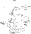
- Fig. 1 represents an external appearance of a dental medical device 1 including a dental chair 10.
- Figs. 2A and 2B represent external appearances of the dental chair 10, and
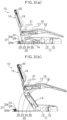
- Figs. 3A and 3B represent a side cross-section of the dental chair 10.
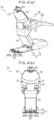
- Figs. 24 and 4B represent an embodiment of a dental foot switch 27 in the dental chair 10. In the following description, it is assumed, as illustrated in Fig.
- the dental medical device 1 includes the dental chair 10 over which a subject, namely a patient, lies, a spittoon 2 into which the patient exhales water in the mouth, a dental light 3 that illuminates the mouth of the patient, an instrument holder 4 that holds various instruments (not illustrated), and a doctor table 5 that holds instruments as with the instrument holder 4 and that includes a panel for controlling the dental light 3, the instruments, and so on.
- the spittoon 2, the dental light 3, the instrument holder 4, and the doctor table 5 are supported by a main unit 6.
- the main unit 6 is installed adjacent to the dental chair 10.
- the spittoon 2 is a bowl and is mounted on the main unit 6.
- the dental light 3 is connected to a tip end of a first movable arm 7 that is attached to the main unit 6.
- the instrument holder 4 is connected to a tip end of a second movable arm 8 that is attached to the main unit 6.
- the doctor table 5 is connected to a tip end of a third movable arm 9 that is attached to the main unit 6.
- Each of the movable arms 7, 8 and 9 has multiple joints. Therefore, the dental light 3, the instrument holder 4, and the doctor table 5 are freely movable through the movable arms 7, 8 and 9.
- the instruments are, for example, a turbine, a micromotor, an air motor, a scaler, a syringe, and so on.
- the dental chair 10 includes a base 11 installed on an installation surface, a leg unit 14 coupled to the base 11, a chair unit 15 coupled to the leg unit 14, a lift 22 that lifts and lowers the chair unit 15, and the dental foot switch 27 that is operated to change a state of the dental chair 10.
- the chair unit 15 includes a lower body supporting portion 16 extending forward, a backrest 19 that is disposed behind the lower body supporting portion 16, a headrest 20 that is coupled to an upper end of the backrest 19, and elbow rests 21 disposed on both sides of the lower body supporting portion 16.
- the lower body supporting portion 16 includes a rear-side supporting portion 17 on which the buttocks and the thighs of the patient are laid, and a front-side supporting portion 18 on which the lower legs of the patient are laid, those portions 17 and 18 being formed integrally with each other.
- the backrest 19 is inclined or raised relative to the lower body supporting portion 16.
- the headrest 20 is inclined or raised and lifted or lowered relative to the backrest 19.
- the dental chair 10 performs lifting and lowering motions and inclining (laying-down) and rising motions.
- the dental chair 10 takes a state in which the chair unit 15 is lowered and arranged at a lowermost position, a state in which the chair unit 15 is lifted and arranged at an uppermost position, a state in which the backrest 19 is raised, a state in which the backrest 19 is inclined, a state in which the head rest 20 is raised, a state in which the head rest 20 is inclined, a state in which the head rest 20 is lowered and arranged at a lowermost position, a state in which the head rest 20 is lifted and arranged at an uppermost position, and states in which the individual components are arranged at optional positions between the lowermost position and the uppermost position for each of the above-mentioned states.
- the state of the dental chair 10 is changed from one to another among various states depending on combinations of the above-mentioned states.
- a dental chair in which the head rest 20 is not operated does not take
- the state of the dental chair 10 is further changed depending on, for example, illuminance of the dental light 3, control of the instrument, coming-out of water from the spittoon 2, and so on.
- the base 11 includes a plate-shaped base portion 12 in the form of a flat plate, and a base main body 13 that is attached to an upper front portion of the plate-shaped base portion 12.
- the plate-shaped base portion 12 has a substantially rectangular shape that is elongate in a front-rear direction and includes a line path (not illustrated) formed therein.
- the base main body 13 incorporates, for example, a power supply unit (not illustrated), a control unit (not illustrated), and so on for driving drive units to change the state of the dental chair 10.
- the leg unit 14 is constituted to be laid down toward the installation surface or to be raised up away from the installation surface with the base 11 serving as a fulcrum. Thus, the dental chair 10 is lifted and lowered.
- the leg unit 14 includes the lift 22, and the lift 22 is realized by a parallel link and a drive unit 26 that drives the parallel link.
- the parallel link is constituted by an elongate drive link 23, an elongate driven link 24, and a chair-side link 25 that is coupled to a lower portion of the chair unit 15.
- Each of the drive link 23 and the driven link 24 is coupled to the base 11 at one end and to the chair-side link 25 at the other end.
- the drive unit 26 is, for example, a hydraulic or pneumatic piston cylinder and is connected to the base 11 at one end and to the drive link 23 at the other end.
- the driven link 24 When the piston cylinder extends, the driven link 24 is raised together with the drive link 23 and, at the same time, the chair-side link 25 (the chair unit 15) departs away from the installation surface. Accordingly, the chair unit 15 is lifted. Because the chair unit 15 is lifted with the leg unit 14 being raised up, the chair unit 15 is lifted while advancing along an arc-shaped locus.
- the driven link 24 When the piston cylinder contracts, the driven link 24 is inclined together with the drive link 23 and, at the same time, the chair-side link 25 (the chair unit 15) comes closer to the installation surface. Accordingly, the chair unit 15 is lowered. A locus of the chair unit 15 when lowered is the same as that when the chair unit 15 is lifted.
- the dental foot switch 27 is disposed at a rear end of the base 11 and is constituted as part of the plate-shaped base portion 12. More specifically, the dental foot switch 27 is disposed behind the leg unit 14 in the laid-down state in which the chair unit 15 is lowered to the lowermost position. In other words, the dental foot switch 27 is disposed at a position at which the dental foot switch 27 does not interfere with the leg unit 14 and the chair unit 15.
- the dental foot switch 27 includes a main body 28 that is elongate in the widthwise direction and that projects rearward while curving, and multiple operating controllers 30a, 30b and 30c that are disposed side by side in a lengthwise direction of the main body 28.
- the main body 28 includes a cover 29 that is removably attached to the plate-shaped base portion 12 of the base 11, and selection means 31 that is covered by the cover 29 and that is used to select the state of the dental chair 10 in interlock with the operating controller 30.
- the cover 29 has a shape protruding upward from the plate-shaped base portion 12, and multiple holes corresponding to the number of the operating controllers 30a, 30b and 30c are formed in a rear surface of the cover 29.
- the operating controllers 30a, 30b and 30c are, for example, joystick type controllers.
- the rod-shaped operating controllers 30a, 30b and 30c project rearward from the main body 28 slightly upward relative to the horizontal and are slightly radially oriented in directions away from each other.
- the operating controllers 30a, 30b and 30c are each tilted upward, downward, leftward, and rightward.
- the number, spacing, and angle of the operating controllers are optionally set.
- the selection means 31 correlates the operating controllers 30a, 30b and 30c with the lifting/lowering of the dental chair 10, the motion of the backrest 19, and the motion of the head rest 20.
- the selection means 31 is, for example, a circuit board, a dip switch, or a connector for connecting wirings.
- the operating controllers 30a, 30b and 30c which one of the motions of the dental chair 10 is to be interlocked with the operating controller is set by changing connection of the wirings, selectively turning on/off the dip switch, or connecting the wirings.
- the first operating controller 30a is interlocked with the lifting/lowering of the dental chair 10
- the second operating controller 30b is interlocked with the motion of the backrest 19
- the third operating controller 30c is interlocked with the motion of the head rest 20.
- the first operating controller 30a is interlocked with an operation of establishing a state specified by a height of the dental chair 10 and an angle of the backrest 19, the height and the angle being previously recorded in the control unit, and the second operating controller 30b is interlocked with an operation of returning the dental chair 10 to the previous state.
- the first operating controller 30a is interlocked with adjustment of the illuminance of the dental light 3
- the second operating controller 30b is interlocked with control of the instrument
- the third operating controller 30c is interlocked with the coming-out of water from the spittoon 2.
- the wirings are passed through the line path in the plate-shaped base portion 12 and are connected to the control unit in the base main body 13.
- the dental foot switch 27 and the dental chair 10 are constituted as described above. The advantageous effects of the dental foot switch 27 and the dental chair 10 will be described below.
- the dental foot switch 27 is disposed at the rear end of the base 11 in the dental chair 10 behind the leg unit 14 in the laid-down state in which the chair unit 15 is lowered to the lowermost position, and it is constituted as part of the plate-shaped base portion 12 (see Figs. 2A and 2B ). In other words, the dental foot switch 27 is disposed at the position at which the dental foot switch 27 does not interfere with the leg unit 14 and the chair unit 15. Thus, even in the so-called linkage dental chair, the chair unit 15 and the dental foot switch 27 do not interfere with each other.
- the dental foot switch 27 is constituted as part of the plate-shaped base portion 12, the dental foot switch 27 itself is kept from being unintentionally moved when operated. As a result, a foot switch of the type enabling the operator to easily operate can be selected to constitute the dental foot switch 27.
- a tilting direction of each of the operating controllers 30a, 30b and 30c and a moving direction of the dental chair 10 match with each other. Therefore, the operator can easily envisage a motion of the dental chair 10 in accordance with a foot operation on the operating controller. For example, when the first operating controller 30a is tilted upward, the dental chair 10 is lifted, and when the first operating controller 30a is tilted downward, the dental chair 10 is lowered. When the second operating controller 30b is tilted upward, the backrest 19 is raised, and when the second operating controller 30b is tilted downward, the backrest 19 is inclined.
- the third operating controller 30c When the third operating controller 30c is tilted upward, the head rest 20 is raised or lifted, and when the third operating controller 30c is tilted downward, the head rest 20 is inclined or lowered. Accordingly, the operator can operate the dental chair foot switch 27 during medical treatment without looking at the foot switch.
- the dental chair 10 may be operated by laterally tilting the operating controllers 30a, 30b and 30c leftward or rightward.
- the dental foot switch 27 is disposed at the rear end of the base 11 and hence it is positioned near the backrest 19 of the dental chair 10 on the rear side. Such a position substantially matches with a position at which the leg of the operator is put during the medical treatment. Accordingly, it is easy for the operator to operate the foot switch.
- the dental chair foot switch 27 includes the main body 28 that is elongate in the widthwise direction, and the multiple operating controllers 30a, 30b and 30c that are disposed side by side in the lengthwise direction of the main body 28 (see Figs. 2A and 2B ).
- the multiple operating controllers 30a, 30b and 30c are disposed at positions at which the operating controllers do not interfere with the lifting/lowering of the dental chair 10 and at which the operator can easily operate the controllers.
- the various motions of the dental chair 10 can be optionally interlocked with the operating controllers 30a, 30b and 30c for each controller in accordance with the preference of the operator.
- the main body 28 includes the cover 29 that is removably attached to the plate-shaped base portion 12 of the base 11, and the selection means 31 that is covered by the cover 29 and that is used to select the motion of the dental chair 10 in interlock with the operating controller 30 (see Figs. 3A, 3B , 4A and 4B ). Therefore, after removing the cover 29, the operator or a worker can easily operate the selection means 31 and can simply set, for each of the operating controllers 30a, 30b and 30c, which one of the motions of the dental chair 10 is to be interlocked with the operating controller.
- the dental chair 10 can provide similar advantageous effects to the above-described ones obtained with the dental chair foot switch 27.
- the dental foot switch may be retrofitted to an existing dental chair.
- the dental foot switch is disposed at a position at which the dental foot switch does not interfere with a leg unit and a chair unit of the existing dental chair.
- the operating controller may be oriented laterally, or the dental foot switch may be disposed on a lateral side of the base. Such an embodiment is premised on that the operating controller or the dental foot switch does not interfere with movements of the operator.
- the dental foot switch may be a push switch.
- At least one of the operating controllers is a joystick type controller and other one or more operating controllers may be controllers of, for example, the step-on type to be depressed downward, the volume switch type, the push type continuously operating the dental chair while being pushed, or the ON/OFF type switching the operation and the stop of the dental chair each time pushed.
Landscapes
- Health & Medical Sciences (AREA)
- Life Sciences & Earth Sciences (AREA)
- Animal Behavior & Ethology (AREA)
- General Health & Medical Sciences (AREA)
- Public Health (AREA)
- Veterinary Medicine (AREA)
- Dental Tools And Instruments Or Auxiliary Dental Instruments (AREA)
- Accommodation For Nursing Or Treatment Tables (AREA)
Claims (3)
- Pédale de commutation de chaise dentaire (27) destinée à changer un état d'une chaise dentaire ; la chaise dentaire comprenant :une base (11) qui est installée sur une surface d'installation ;une unité de jambe (14) qui est couplée à la base (11) et qui est reposée vers la surface d'installation ou relevée à partir de celle-ci ; etune unité de chaise (15) qui est couplée à l'unité de jambe (14) et qui est abaissée avec l'unité de jambe (14) quand celle-ci est reposée et est soulevée avec l'unité de jambe (14) quand celle-ci est relevée,caractérisée en ce quela pédale de commutation de chaise dentaire (27) est formée sur une partie de la base (11) autour de l'unité de jambe reposée (14),la pédale de commutation de chaise dentaire (27) est disposée au niveau d'une extrémité arrière de la base (11) sur un côté où l'unité de jambe (14) est reposée, etla pédale de commutation dentaire (27) comporte :un corps principal (28) qui est allongé dans une direction dans le sens de la largeur de l'unité de chaise (15) ; etde multiples moyens de commande de fonctionnement (30a, 30b, 30c) qui sont disposés côte-à-côte dans une direction dans le sens de la longueur du corps principal (28),dans lequel au moins un des moyens de commande de fonctionnement (30a, 30b, 30c) est un moyen de commande de type joystick.
- Pédale de commutation de chaise dentaire (27) destinée à changer un état d'une chaise dentaire selon la revendication 1, caractérisée en ce que le corps principal (28) comporte :un couvercle (29) qui est attaché de manière amovible à la base (11) ; etun moyen de sélection (31) qui est recouvert par le couvercle (29) et qui est utilisé pour sélectionner un mouvement de la chaise dentaire en enclenchement avec le moyen de commande de fonctionnement (30a, 30b, 30c).
- Chaise dentaire comprenant la pédale de commutation de chaise dentaire (27) selon la revendication 1 ou 2.
Applications Claiming Priority (1)
| Application Number | Priority Date | Filing Date | Title |
|---|---|---|---|
| PCT/JP2018/031398 WO2020039585A1 (fr) | 2018-08-24 | 2018-08-24 | Pédale de commutation de chaise dentaire |
Publications (3)
| Publication Number | Publication Date |
|---|---|
| EP3842022A1 EP3842022A1 (fr) | 2021-06-30 |
| EP3842022A4 EP3842022A4 (fr) | 2022-04-06 |
| EP3842022B1 true EP3842022B1 (fr) | 2023-02-08 |
Family
ID=69592920
Family Applications (1)
| Application Number | Title | Priority Date | Filing Date |
|---|---|---|---|
| EP18930897.6A Active EP3842022B1 (fr) | 2018-08-24 | 2018-08-24 | Pédale de commutation de chaise dentaire |
Country Status (3)
| Country | Link |
|---|---|
| EP (1) | EP3842022B1 (fr) |
| JP (1) | JP6784832B2 (fr) |
| WO (1) | WO2020039585A1 (fr) |
Families Citing this family (1)
| Publication number | Priority date | Publication date | Assignee | Title |
|---|---|---|---|---|
| KR102512763B1 (ko) * | 2016-07-15 | 2023-03-22 | 서지박스 인코포레이티드 | 외과 수술 환경들에서의 수술 중에 행하는 격리 및 통제를 위한 울트라포터블 시스템 |
Family Cites Families (7)
| Publication number | Priority date | Publication date | Assignee | Title |
|---|---|---|---|---|
| JPS589136U (ja) * | 1981-07-06 | 1983-01-21 | 株式会社吉田製作所 | 歯科用治療椅子 |
| DE10014063A1 (de) * | 2000-03-22 | 2001-09-27 | Kaltenbach & Voigt | Medizinischer oder dentalmedizinischer Behandlungsstuhl oder eine Kopfstütze für einen solchen Behandlungsstuhl |
| DE20105249U1 (de) | 2001-03-26 | 2001-07-05 | Kaltenbach & Voigt GmbH & Co., 88400 Biberach | Dentaler Behandlungsstuhl mit einer schwenkbar gelagerten Speischale |
| JP4200042B2 (ja) * | 2003-04-24 | 2008-12-24 | 株式会社モリタ製作所 | 医療用診療台及び医療用診療台用のフートコントローラ |
| DE102006057306A1 (de) * | 2006-12-05 | 2008-06-12 | Kg Brumaba | Vorrichtung zur selektiven Betätigung mehrerer Schalter oder Schaltkontakte |
| JP2009022512A (ja) * | 2007-07-19 | 2009-02-05 | Osada Res Inst Ltd | 歯科用治療椅子 |
| JP6250348B2 (ja) | 2013-09-27 | 2017-12-20 | 株式会社ジーシー | 歯科ユニット |
-
2018
- 2018-08-24 WO PCT/JP2018/031398 patent/WO2020039585A1/fr not_active Ceased
- 2018-08-24 JP JP2019514043A patent/JP6784832B2/ja active Active
- 2018-08-24 EP EP18930897.6A patent/EP3842022B1/fr active Active
Also Published As
| Publication number | Publication date |
|---|---|
| EP3842022A1 (fr) | 2021-06-30 |
| WO2020039585A1 (fr) | 2020-02-27 |
| EP3842022A4 (fr) | 2022-04-06 |
| JP6784832B2 (ja) | 2020-11-11 |
| JPWO2020039585A1 (ja) | 2020-08-27 |
Similar Documents
| Publication | Publication Date | Title |
|---|---|---|
| JP5594768B2 (ja) | 電動式ベッドの操作機構 | |
| US20230221748A1 (en) | Foot pedal apparatus for use with a workstation controlling a robotic surgery system | |
| JP2597326Y2 (ja) | 歯科の患者用椅子 | |
| JP5694853B2 (ja) | ヘッドレストを備える椅子 | |
| EP3842022A1 (fr) | Pédale de commutation de chaise dentaire | |
| JP2005124796A (ja) | ヘッドレスト装置及びそれを備えた医療用椅子並びに医療用ベッド | |
| JP2009006023A (ja) | 医療用椅子 | |
| NO339533B1 (en) | Operator chair | |
| CN115590717A (zh) | 一种牙科治疗椅 | |
| JP5373529B2 (ja) | 歯科ユニット | |
| KR101990314B1 (ko) | 치과 의사용 의자 어셈블리 및 이를 포함하는 유니트 체어 시스템 | |
| JP2009022512A (ja) | 歯科用治療椅子 | |
| JP2002345905A (ja) | 歯科用ユニット | |
| JP6074654B2 (ja) | ロボット | |
| JP2011036589A (ja) | 歯科ユニット | |
| JP2011229715A (ja) | 歯科用治療椅子 | |
| US3280462A (en) | Dental unit | |
| CN212997229U (zh) | 椅旁式牙科移动治疗车 | |
| JP2005124798A (ja) | 椅子 | |
| WO2009073027A1 (fr) | Fauteuil dentaire avec positionnement amélioré du patient | |
| CN223111934U (zh) | 控制调节结构及牙科椅 | |
| JP2001204768A (ja) | 車椅子 | |
| JP5294478B2 (ja) | 歯科診療台 | |
| CN115813557A (zh) | 一种脚踏组件、脚踏控制台及其控制方法、手术控制台及手术机器人系统 | |
| JP4796762B2 (ja) | 医療用診療装置 |
Legal Events
| Date | Code | Title | Description |
|---|---|---|---|
| STAA | Information on the status of an ep patent application or granted ep patent |
Free format text: STATUS: THE INTERNATIONAL PUBLICATION HAS BEEN MADE |
|
| PUAI | Public reference made under article 153(3) epc to a published international application that has entered the european phase |
Free format text: ORIGINAL CODE: 0009012 |
|
| STAA | Information on the status of an ep patent application or granted ep patent |
Free format text: STATUS: REQUEST FOR EXAMINATION WAS MADE |
|
| 17P | Request for examination filed |
Effective date: 20210323 |
|
| AK | Designated contracting states |
Kind code of ref document: A1 Designated state(s): AL AT BE BG CH CY CZ DE DK EE ES FI FR GB GR HR HU IE IS IT LI LT LU LV MC MK MT NL NO PL PT RO RS SE SI SK SM TR |
|
| DAV | Request for validation of the european patent (deleted) | ||
| DAX | Request for extension of the european patent (deleted) | ||
| A4 | Supplementary search report drawn up and despatched |
Effective date: 20220307 |
|
| RIC1 | Information provided on ipc code assigned before grant |
Ipc: A61G 15/10 20060101ALI20220301BHEP Ipc: A61G 15/00 20060101AFI20220301BHEP |
|
| REG | Reference to a national code |
Ref country code: DE Ref legal event code: R079 Ref document number: 602018046075 Country of ref document: DE Free format text: PREVIOUS MAIN CLASS: A61G0015000000 Ipc: A61G0015020000 |
|
| GRAP | Despatch of communication of intention to grant a patent |
Free format text: ORIGINAL CODE: EPIDOSNIGR1 |
|
| STAA | Information on the status of an ep patent application or granted ep patent |
Free format text: STATUS: GRANT OF PATENT IS INTENDED |
|
| RIC1 | Information provided on ipc code assigned before grant |
Ipc: A61G 15/10 20060101ALI20220808BHEP Ipc: A61G 15/02 20060101AFI20220808BHEP |
|
| INTG | Intention to grant announced |
Effective date: 20220901 |
|
| GRAS | Grant fee paid |
Free format text: ORIGINAL CODE: EPIDOSNIGR3 |
|
| GRAA | (expected) grant |
Free format text: ORIGINAL CODE: 0009210 |
|
| STAA | Information on the status of an ep patent application or granted ep patent |
Free format text: STATUS: THE PATENT HAS BEEN GRANTED |
|
| AK | Designated contracting states |
Kind code of ref document: B1 Designated state(s): AL AT BE BG CH CY CZ DE DK EE ES FI FR GB GR HR HU IE IS IT LI LT LU LV MC MK MT NL NO PL PT RO RS SE SI SK SM TR |
|
| REG | Reference to a national code |
Ref country code: GB Ref legal event code: FG4D |
|
| REG | Reference to a national code |
Ref country code: CH Ref legal event code: EP Ref country code: AT Ref legal event code: REF Ref document number: 1547296 Country of ref document: AT Kind code of ref document: T Effective date: 20230215 |
|
| REG | Reference to a national code |
Ref country code: IE Ref legal event code: FG4D |
|
| REG | Reference to a national code |
Ref country code: DE Ref legal event code: R096 Ref document number: 602018046075 Country of ref document: DE |
|
| REG | Reference to a national code |
Ref country code: LT Ref legal event code: MG9D |
|
| REG | Reference to a national code |
Ref country code: NL Ref legal event code: MP Effective date: 20230208 |
|
| REG | Reference to a national code |
Ref country code: AT Ref legal event code: MK05 Ref document number: 1547296 Country of ref document: AT Kind code of ref document: T Effective date: 20230208 |
|
| PG25 | Lapsed in a contracting state [announced via postgrant information from national office to epo] |
Ref country code: RS Free format text: LAPSE BECAUSE OF FAILURE TO SUBMIT A TRANSLATION OF THE DESCRIPTION OR TO PAY THE FEE WITHIN THE PRESCRIBED TIME-LIMIT Effective date: 20230208 Ref country code: PT Free format text: LAPSE BECAUSE OF FAILURE TO SUBMIT A TRANSLATION OF THE DESCRIPTION OR TO PAY THE FEE WITHIN THE PRESCRIBED TIME-LIMIT Effective date: 20230609 Ref country code: NO Free format text: LAPSE BECAUSE OF FAILURE TO SUBMIT A TRANSLATION OF THE DESCRIPTION OR TO PAY THE FEE WITHIN THE PRESCRIBED TIME-LIMIT Effective date: 20230508 Ref country code: NL Free format text: LAPSE BECAUSE OF FAILURE TO SUBMIT A TRANSLATION OF THE DESCRIPTION OR TO PAY THE FEE WITHIN THE PRESCRIBED TIME-LIMIT Effective date: 20230208 Ref country code: LV Free format text: LAPSE BECAUSE OF FAILURE TO SUBMIT A TRANSLATION OF THE DESCRIPTION OR TO PAY THE FEE WITHIN THE PRESCRIBED TIME-LIMIT Effective date: 20230208 Ref country code: LT Free format text: LAPSE BECAUSE OF FAILURE TO SUBMIT A TRANSLATION OF THE DESCRIPTION OR TO PAY THE FEE WITHIN THE PRESCRIBED TIME-LIMIT Effective date: 20230208 Ref country code: HR Free format text: LAPSE BECAUSE OF FAILURE TO SUBMIT A TRANSLATION OF THE DESCRIPTION OR TO PAY THE FEE WITHIN THE PRESCRIBED TIME-LIMIT Effective date: 20230208 Ref country code: ES Free format text: LAPSE BECAUSE OF FAILURE TO SUBMIT A TRANSLATION OF THE DESCRIPTION OR TO PAY THE FEE WITHIN THE PRESCRIBED TIME-LIMIT Effective date: 20230208 Ref country code: AT Free format text: LAPSE BECAUSE OF FAILURE TO SUBMIT A TRANSLATION OF THE DESCRIPTION OR TO PAY THE FEE WITHIN THE PRESCRIBED TIME-LIMIT Effective date: 20230208 |
|
| PG25 | Lapsed in a contracting state [announced via postgrant information from national office to epo] |
Ref country code: SE Free format text: LAPSE BECAUSE OF FAILURE TO SUBMIT A TRANSLATION OF THE DESCRIPTION OR TO PAY THE FEE WITHIN THE PRESCRIBED TIME-LIMIT Effective date: 20230208 Ref country code: PL Free format text: LAPSE BECAUSE OF FAILURE TO SUBMIT A TRANSLATION OF THE DESCRIPTION OR TO PAY THE FEE WITHIN THE PRESCRIBED TIME-LIMIT Effective date: 20230208 Ref country code: IS Free format text: LAPSE BECAUSE OF FAILURE TO SUBMIT A TRANSLATION OF THE DESCRIPTION OR TO PAY THE FEE WITHIN THE PRESCRIBED TIME-LIMIT Effective date: 20230608 Ref country code: GR Free format text: LAPSE BECAUSE OF FAILURE TO SUBMIT A TRANSLATION OF THE DESCRIPTION OR TO PAY THE FEE WITHIN THE PRESCRIBED TIME-LIMIT Effective date: 20230509 Ref country code: FI Free format text: LAPSE BECAUSE OF FAILURE TO SUBMIT A TRANSLATION OF THE DESCRIPTION OR TO PAY THE FEE WITHIN THE PRESCRIBED TIME-LIMIT Effective date: 20230208 |
|
| PG25 | Lapsed in a contracting state [announced via postgrant information from national office to epo] |
Ref country code: SM Free format text: LAPSE BECAUSE OF FAILURE TO SUBMIT A TRANSLATION OF THE DESCRIPTION OR TO PAY THE FEE WITHIN THE PRESCRIBED TIME-LIMIT Effective date: 20230208 Ref country code: RO Free format text: LAPSE BECAUSE OF FAILURE TO SUBMIT A TRANSLATION OF THE DESCRIPTION OR TO PAY THE FEE WITHIN THE PRESCRIBED TIME-LIMIT Effective date: 20230208 Ref country code: EE Free format text: LAPSE BECAUSE OF FAILURE TO SUBMIT A TRANSLATION OF THE DESCRIPTION OR TO PAY THE FEE WITHIN THE PRESCRIBED TIME-LIMIT Effective date: 20230208 Ref country code: DK Free format text: LAPSE BECAUSE OF FAILURE TO SUBMIT A TRANSLATION OF THE DESCRIPTION OR TO PAY THE FEE WITHIN THE PRESCRIBED TIME-LIMIT Effective date: 20230208 Ref country code: CZ Free format text: LAPSE BECAUSE OF FAILURE TO SUBMIT A TRANSLATION OF THE DESCRIPTION OR TO PAY THE FEE WITHIN THE PRESCRIBED TIME-LIMIT Effective date: 20230208 |
|
| REG | Reference to a national code |
Ref country code: DE Ref legal event code: R097 Ref document number: 602018046075 Country of ref document: DE |
|
| PG25 | Lapsed in a contracting state [announced via postgrant information from national office to epo] |
Ref country code: SK Free format text: LAPSE BECAUSE OF FAILURE TO SUBMIT A TRANSLATION OF THE DESCRIPTION OR TO PAY THE FEE WITHIN THE PRESCRIBED TIME-LIMIT Effective date: 20230208 |
|
| PLBE | No opposition filed within time limit |
Free format text: ORIGINAL CODE: 0009261 |
|
| STAA | Information on the status of an ep patent application or granted ep patent |
Free format text: STATUS: NO OPPOSITION FILED WITHIN TIME LIMIT |
|
| 26N | No opposition filed |
Effective date: 20231109 |
|
| PG25 | Lapsed in a contracting state [announced via postgrant information from national office to epo] |
Ref country code: SI Free format text: LAPSE BECAUSE OF FAILURE TO SUBMIT A TRANSLATION OF THE DESCRIPTION OR TO PAY THE FEE WITHIN THE PRESCRIBED TIME-LIMIT Effective date: 20230208 |
|
| PG25 | Lapsed in a contracting state [announced via postgrant information from national office to epo] |
Ref country code: MC Free format text: LAPSE BECAUSE OF FAILURE TO SUBMIT A TRANSLATION OF THE DESCRIPTION OR TO PAY THE FEE WITHIN THE PRESCRIBED TIME-LIMIT Effective date: 20230208 |
|
| REG | Reference to a national code |
Ref country code: CH Ref legal event code: PL |
|
| PG25 | Lapsed in a contracting state [announced via postgrant information from national office to epo] |
Ref country code: MC Free format text: LAPSE BECAUSE OF FAILURE TO SUBMIT A TRANSLATION OF THE DESCRIPTION OR TO PAY THE FEE WITHIN THE PRESCRIBED TIME-LIMIT Effective date: 20230208 |
|
| PG25 | Lapsed in a contracting state [announced via postgrant information from national office to epo] |
Ref country code: LU Free format text: LAPSE BECAUSE OF NON-PAYMENT OF DUE FEES Effective date: 20230824 |
|
| PG25 | Lapsed in a contracting state [announced via postgrant information from national office to epo] |
Ref country code: LU Free format text: LAPSE BECAUSE OF NON-PAYMENT OF DUE FEES Effective date: 20230824 Ref country code: CH Free format text: LAPSE BECAUSE OF NON-PAYMENT OF DUE FEES Effective date: 20230831 |
|
| REG | Reference to a national code |
Ref country code: BE Ref legal event code: MM Effective date: 20230831 |
|
| REG | Reference to a national code |
Ref country code: IE Ref legal event code: MM4A |
|
| PG25 | Lapsed in a contracting state [announced via postgrant information from national office to epo] |
Ref country code: IE Free format text: LAPSE BECAUSE OF NON-PAYMENT OF DUE FEES Effective date: 20230824 |
|
| PG25 | Lapsed in a contracting state [announced via postgrant information from national office to epo] |
Ref country code: IE Free format text: LAPSE BECAUSE OF NON-PAYMENT OF DUE FEES Effective date: 20230824 |
|
| PG25 | Lapsed in a contracting state [announced via postgrant information from national office to epo] |
Ref country code: BE Free format text: LAPSE BECAUSE OF NON-PAYMENT OF DUE FEES Effective date: 20230831 |
|
| PG25 | Lapsed in a contracting state [announced via postgrant information from national office to epo] |
Ref country code: BG Free format text: LAPSE BECAUSE OF FAILURE TO SUBMIT A TRANSLATION OF THE DESCRIPTION OR TO PAY THE FEE WITHIN THE PRESCRIBED TIME-LIMIT Effective date: 20230208 |
|
| PG25 | Lapsed in a contracting state [announced via postgrant information from national office to epo] |
Ref country code: BG Free format text: LAPSE BECAUSE OF FAILURE TO SUBMIT A TRANSLATION OF THE DESCRIPTION OR TO PAY THE FEE WITHIN THE PRESCRIBED TIME-LIMIT Effective date: 20230208 |
|
| PG25 | Lapsed in a contracting state [announced via postgrant information from national office to epo] |
Ref country code: CY Free format text: LAPSE BECAUSE OF FAILURE TO SUBMIT A TRANSLATION OF THE DESCRIPTION OR TO PAY THE FEE WITHIN THE PRESCRIBED TIME-LIMIT; INVALID AB INITIO Effective date: 20180824 |
|
| PG25 | Lapsed in a contracting state [announced via postgrant information from national office to epo] |
Ref country code: HU Free format text: LAPSE BECAUSE OF FAILURE TO SUBMIT A TRANSLATION OF THE DESCRIPTION OR TO PAY THE FEE WITHIN THE PRESCRIBED TIME-LIMIT; INVALID AB INITIO Effective date: 20180824 |
|
| PGFP | Annual fee paid to national office [announced via postgrant information from national office to epo] |
Ref country code: DE Payment date: 20250820 Year of fee payment: 8 |
|
| PGFP | Annual fee paid to national office [announced via postgrant information from national office to epo] |
Ref country code: IT Payment date: 20250825 Year of fee payment: 8 |
|
| PGFP | Annual fee paid to national office [announced via postgrant information from national office to epo] |
Ref country code: GB Payment date: 20250820 Year of fee payment: 8 |
|
| PGFP | Annual fee paid to national office [announced via postgrant information from national office to epo] |
Ref country code: FR Payment date: 20250828 Year of fee payment: 8 |
|
| PG25 | Lapsed in a contracting state [announced via postgrant information from national office to epo] |
Ref country code: TR Free format text: LAPSE BECAUSE OF FAILURE TO SUBMIT A TRANSLATION OF THE DESCRIPTION OR TO PAY THE FEE WITHIN THE PRESCRIBED TIME-LIMIT Effective date: 20230208 |