EP3842142A1 - Abgasreinigungskatalysator - Google Patents
Abgasreinigungskatalysator Download PDFInfo
- Publication number
- EP3842142A1 EP3842142A1 EP19852457.1A EP19852457A EP3842142A1 EP 3842142 A1 EP3842142 A1 EP 3842142A1 EP 19852457 A EP19852457 A EP 19852457A EP 3842142 A1 EP3842142 A1 EP 3842142A1
- Authority
- EP
- European Patent Office
- Prior art keywords
- catalyst
- exhaust gas
- catalyst layer
- partition wall
- layer
- Prior art date
- Legal status (The legal status is an assumption and is not a legal conclusion. Google has not performed a legal analysis and makes no representation as to the accuracy of the status listed.)
- Granted
Links
Images


Classifications
-
- F—MECHANICAL ENGINEERING; LIGHTING; HEATING; WEAPONS; BLASTING
- F01—MACHINES OR ENGINES IN GENERAL; ENGINE PLANTS IN GENERAL; STEAM ENGINES
- F01N—GAS-FLOW SILENCERS OR EXHAUST APPARATUS FOR MACHINES OR ENGINES IN GENERAL; GAS-FLOW SILENCERS OR EXHAUST APPARATUS FOR INTERNAL-COMBUSTION ENGINES
- F01N3/00—Exhaust or silencing apparatus having means for purifying, rendering innocuous, or otherwise treating exhaust
- F01N3/08—Exhaust or silencing apparatus having means for purifying, rendering innocuous, or otherwise treating exhaust for rendering innocuous
- F01N3/10—Exhaust or silencing apparatus having means for purifying, rendering innocuous, or otherwise treating exhaust for rendering innocuous by thermal or catalytic conversion of noxious components of exhaust
- F01N3/24—Exhaust or silencing apparatus having means for purifying, rendering innocuous, or otherwise treating exhaust for rendering innocuous by thermal or catalytic conversion of noxious components of exhaust characterised by constructional aspects of converting apparatus
- F01N3/28—Construction of catalytic reactors
- F01N3/2803—Construction of catalytic reactors characterised by structure, by material or by manufacturing of catalyst support
- F01N3/2807—Metal other than sintered metal
- F01N3/281—Metallic honeycomb monoliths made of stacked or rolled sheets, foils or plates
- F01N3/2821—Metallic honeycomb monoliths made of stacked or rolled sheets, foils or plates the support being provided with means to enhance the mixing process inside the converter, e.g. sheets, plates or foils with protrusions or projections to create turbulence
-
- B—PERFORMING OPERATIONS; TRANSPORTING
- B01—PHYSICAL OR CHEMICAL PROCESSES OR APPARATUS IN GENERAL
- B01J—CHEMICAL OR PHYSICAL PROCESSES, e.g. CATALYSIS OR COLLOID CHEMISTRY; THEIR RELEVANT APPARATUS
- B01J23/00—Catalysts comprising metals or metal oxides or hydroxides, not provided for in group B01J21/00
- B01J23/38—Catalysts comprising metals or metal oxides or hydroxides, not provided for in group B01J21/00 of noble metals
- B01J23/54—Catalysts comprising metals or metal oxides or hydroxides, not provided for in group B01J21/00 of noble metals combined with metals, oxides or hydroxides provided for in groups B01J23/02 - B01J23/36
- B01J23/56—Platinum group metals
- B01J23/63—Platinum group metals with rare earths or actinides
-
- B—PERFORMING OPERATIONS; TRANSPORTING
- B01—PHYSICAL OR CHEMICAL PROCESSES OR APPARATUS IN GENERAL
- B01D—SEPARATION
- B01D53/00—Separation of gases or vapours; Recovering vapours of volatile solvents from gases; Chemical or biological purification of waste gases, e.g. engine exhaust gases, smoke, fumes, flue gases, aerosols
- B01D53/34—Chemical or biological purification of waste gases
- B01D53/92—Chemical or biological purification of waste gases of engine exhaust gases
- B01D53/94—Chemical or biological purification of waste gases of engine exhaust gases by catalytic processes
- B01D53/9445—Simultaneously removing carbon monoxide, hydrocarbons or nitrogen oxides making use of three-way catalysts [TWC] or four-way-catalysts [FWC]
- B01D53/945—Simultaneously removing carbon monoxide, hydrocarbons or nitrogen oxides making use of three-way catalysts [TWC] or four-way-catalysts [FWC] characterised by a specific catalyst
-
- B—PERFORMING OPERATIONS; TRANSPORTING
- B01—PHYSICAL OR CHEMICAL PROCESSES OR APPARATUS IN GENERAL
- B01D—SEPARATION
- B01D53/00—Separation of gases or vapours; Recovering vapours of volatile solvents from gases; Chemical or biological purification of waste gases, e.g. engine exhaust gases, smoke, fumes, flue gases, aerosols
- B01D53/34—Chemical or biological purification of waste gases
- B01D53/92—Chemical or biological purification of waste gases of engine exhaust gases
- B01D53/94—Chemical or biological purification of waste gases of engine exhaust gases by catalytic processes
- B01D53/9459—Removing one or more of nitrogen oxides, carbon monoxide, or hydrocarbons by multiple successive catalytic functions; systems with more than one different function, e.g. zone coated catalysts
- B01D53/9463—Removing one or more of nitrogen oxides, carbon monoxide, or hydrocarbons by multiple successive catalytic functions; systems with more than one different function, e.g. zone coated catalysts with catalysts positioned on one brick
- B01D53/9468—Removing one or more of nitrogen oxides, carbon monoxide, or hydrocarbons by multiple successive catalytic functions; systems with more than one different function, e.g. zone coated catalysts with catalysts positioned on one brick in different layers
-
- B—PERFORMING OPERATIONS; TRANSPORTING
- B01—PHYSICAL OR CHEMICAL PROCESSES OR APPARATUS IN GENERAL
- B01D—SEPARATION
- B01D53/00—Separation of gases or vapours; Recovering vapours of volatile solvents from gases; Chemical or biological purification of waste gases, e.g. engine exhaust gases, smoke, fumes, flue gases, aerosols
- B01D53/34—Chemical or biological purification of waste gases
- B01D53/92—Chemical or biological purification of waste gases of engine exhaust gases
- B01D53/94—Chemical or biological purification of waste gases of engine exhaust gases by catalytic processes
- B01D53/9459—Removing one or more of nitrogen oxides, carbon monoxide, or hydrocarbons by multiple successive catalytic functions; systems with more than one different function, e.g. zone coated catalysts
- B01D53/9463—Removing one or more of nitrogen oxides, carbon monoxide, or hydrocarbons by multiple successive catalytic functions; systems with more than one different function, e.g. zone coated catalysts with catalysts positioned on one brick
- B01D53/9472—Removing one or more of nitrogen oxides, carbon monoxide, or hydrocarbons by multiple successive catalytic functions; systems with more than one different function, e.g. zone coated catalysts with catalysts positioned on one brick in different zones
-
- B—PERFORMING OPERATIONS; TRANSPORTING
- B01—PHYSICAL OR CHEMICAL PROCESSES OR APPARATUS IN GENERAL
- B01J—CHEMICAL OR PHYSICAL PROCESSES, e.g. CATALYSIS OR COLLOID CHEMISTRY; THEIR RELEVANT APPARATUS
- B01J35/00—Catalysts, in general, characterised by their form or physical properties
- B01J35/50—Catalysts, in general, characterised by their form or physical properties characterised by their shape or configuration
- B01J35/56—Foraminous structures having flow-through passages or channels, e.g. grids or three-dimensional [3D] monoliths
-
- B—PERFORMING OPERATIONS; TRANSPORTING
- B01—PHYSICAL OR CHEMICAL PROCESSES OR APPARATUS IN GENERAL
- B01J—CHEMICAL OR PHYSICAL PROCESSES, e.g. CATALYSIS OR COLLOID CHEMISTRY; THEIR RELEVANT APPARATUS
- B01J35/00—Catalysts, in general, characterised by their form or physical properties
- B01J35/60—Catalysts, in general, characterised by their form or physical properties characterised by their surface properties or porosity
-
- F—MECHANICAL ENGINEERING; LIGHTING; HEATING; WEAPONS; BLASTING
- F01—MACHINES OR ENGINES IN GENERAL; ENGINE PLANTS IN GENERAL; STEAM ENGINES
- F01N—GAS-FLOW SILENCERS OR EXHAUST APPARATUS FOR MACHINES OR ENGINES IN GENERAL; GAS-FLOW SILENCERS OR EXHAUST APPARATUS FOR INTERNAL-COMBUSTION ENGINES
- F01N3/00—Exhaust or silencing apparatus having means for purifying, rendering innocuous, or otherwise treating exhaust
- F01N3/02—Exhaust or silencing apparatus having means for purifying, rendering innocuous, or otherwise treating exhaust for cooling, or for removing solid constituents of, exhaust
- F01N3/021—Exhaust or silencing apparatus having means for purifying, rendering innocuous, or otherwise treating exhaust for cooling, or for removing solid constituents of, exhaust by means of filters
- F01N3/033—Exhaust or silencing apparatus having means for purifying, rendering innocuous, or otherwise treating exhaust for cooling, or for removing solid constituents of, exhaust by means of filters in combination with other devices
- F01N3/035—Exhaust or silencing apparatus having means for purifying, rendering innocuous, or otherwise treating exhaust for cooling, or for removing solid constituents of, exhaust by means of filters in combination with other devices with catalytic reactors
-
- F—MECHANICAL ENGINEERING; LIGHTING; HEATING; WEAPONS; BLASTING
- F01—MACHINES OR ENGINES IN GENERAL; ENGINE PLANTS IN GENERAL; STEAM ENGINES
- F01N—GAS-FLOW SILENCERS OR EXHAUST APPARATUS FOR MACHINES OR ENGINES IN GENERAL; GAS-FLOW SILENCERS OR EXHAUST APPARATUS FOR INTERNAL-COMBUSTION ENGINES
- F01N3/00—Exhaust or silencing apparatus having means for purifying, rendering innocuous, or otherwise treating exhaust
- F01N3/08—Exhaust or silencing apparatus having means for purifying, rendering innocuous, or otherwise treating exhaust for rendering innocuous
- F01N3/10—Exhaust or silencing apparatus having means for purifying, rendering innocuous, or otherwise treating exhaust for rendering innocuous by thermal or catalytic conversion of noxious components of exhaust
- F01N3/24—Exhaust or silencing apparatus having means for purifying, rendering innocuous, or otherwise treating exhaust for rendering innocuous by thermal or catalytic conversion of noxious components of exhaust characterised by constructional aspects of converting apparatus
- F01N3/28—Construction of catalytic reactors
-
- F—MECHANICAL ENGINEERING; LIGHTING; HEATING; WEAPONS; BLASTING
- F01—MACHINES OR ENGINES IN GENERAL; ENGINE PLANTS IN GENERAL; STEAM ENGINES
- F01N—GAS-FLOW SILENCERS OR EXHAUST APPARATUS FOR MACHINES OR ENGINES IN GENERAL; GAS-FLOW SILENCERS OR EXHAUST APPARATUS FOR INTERNAL-COMBUSTION ENGINES
- F01N3/00—Exhaust or silencing apparatus having means for purifying, rendering innocuous, or otherwise treating exhaust
- F01N3/08—Exhaust or silencing apparatus having means for purifying, rendering innocuous, or otherwise treating exhaust for rendering innocuous
- F01N3/10—Exhaust or silencing apparatus having means for purifying, rendering innocuous, or otherwise treating exhaust for rendering innocuous by thermal or catalytic conversion of noxious components of exhaust
- F01N3/24—Exhaust or silencing apparatus having means for purifying, rendering innocuous, or otherwise treating exhaust for rendering innocuous by thermal or catalytic conversion of noxious components of exhaust characterised by constructional aspects of converting apparatus
- F01N3/28—Construction of catalytic reactors
- F01N3/2803—Construction of catalytic reactors characterised by structure, by material or by manufacturing of catalyst support
- F01N3/2825—Ceramics
- F01N3/2828—Ceramic multi-channel monoliths, e.g. honeycombs
-
- B—PERFORMING OPERATIONS; TRANSPORTING
- B01—PHYSICAL OR CHEMICAL PROCESSES OR APPARATUS IN GENERAL
- B01D—SEPARATION
- B01D2255/00—Catalysts
- B01D2255/10—Noble metals or compounds thereof
- B01D2255/102—Platinum group metals
- B01D2255/1023—Palladium
-
- B—PERFORMING OPERATIONS; TRANSPORTING
- B01—PHYSICAL OR CHEMICAL PROCESSES OR APPARATUS IN GENERAL
- B01D—SEPARATION
- B01D2255/00—Catalysts
- B01D2255/10—Noble metals or compounds thereof
- B01D2255/102—Platinum group metals
- B01D2255/1025—Rhodium
-
- B—PERFORMING OPERATIONS; TRANSPORTING
- B01—PHYSICAL OR CHEMICAL PROCESSES OR APPARATUS IN GENERAL
- B01D—SEPARATION
- B01D2255/00—Catalysts
- B01D2255/20—Metals or compounds thereof
- B01D2255/209—Other metals
- B01D2255/2092—Aluminium
-
- B—PERFORMING OPERATIONS; TRANSPORTING
- B01—PHYSICAL OR CHEMICAL PROCESSES OR APPARATUS IN GENERAL
- B01D—SEPARATION
- B01D2255/00—Catalysts
- B01D2255/40—Mixed oxides
- B01D2255/407—Zr-Ce mixed oxides
-
- Y—GENERAL TAGGING OF NEW TECHNOLOGICAL DEVELOPMENTS; GENERAL TAGGING OF CROSS-SECTIONAL TECHNOLOGIES SPANNING OVER SEVERAL SECTIONS OF THE IPC; TECHNICAL SUBJECTS COVERED BY FORMER USPC CROSS-REFERENCE ART COLLECTIONS [XRACs] AND DIGESTS
- Y02—TECHNOLOGIES OR APPLICATIONS FOR MITIGATION OR ADAPTATION AGAINST CLIMATE CHANGE
- Y02T—CLIMATE CHANGE MITIGATION TECHNOLOGIES RELATED TO TRANSPORTATION
- Y02T10/00—Road transport of goods or passengers
- Y02T10/10—Internal combustion engine [ICE] based vehicles
- Y02T10/12—Improving ICE efficiencies
Definitions
- the present invention relates to an exhaust gas purifying catalyst.
- GDI engines gasoline direct injection engines
- PM particulate matter
- GPF gasoline particulate filter
- an exhaust gas purifying catalyst In general, the space for installing an exhaust gas purifying catalyst in vehicles is limited, and thus, in view of space-saving, an exhaust gas purifying catalyst has come into use in recent years that includes a filter as described above and a noble metal three-way catalyst component such as Pd, Pt, or Rh supported on the filter to collect PM and purify nitrogen oxide (NO x ), carbon monoxide (CO), hydrocarbon (HC), and the like.
- a noble metal three-way catalyst component such as Pd, Pt, or Rh supported on the filter to collect PM and purify nitrogen oxide (NO x ), carbon monoxide (CO), hydrocarbon (HC), and the like.
- Patent Literature 1 discloses a treatment system for a gasoline engine exhaust gas stream including a particulate filter, the particulate filter including a particulate filter substrate, an inlet layer disposed on the exhaust gas inlet surface of the filter substrate, and an outlet layer disposed on the exhaust gas outlet surface of the filter substrate, wherein the inlet layer includes Rh and/or Pd and the outlet layer includes Rh and/or a zeolite.
- Patent Literature 1 US 20110030346A1
- the inventors of the present invention have conducted in-depth studies on the configuration of a filter catalyst that has a wall flow structure. As a result, they have found that a filter catalyst that has better exhaust gas purification performance than a conventional filter catalyst can be obtained by arranging an oxidizing catalyst layer and a reducing catalyst layer under specific conditions on an inlet side and an outlet side of a substrate.
- the present invention has been made based on the findings described above, and provides an exhaust gas purifying catalyst including a substrate and catalyst portions provided in the substrate, the substrate including:
- a filter catalyst that has superior exhaust gas purification performance to that of a conventional filter catalyst.
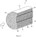
- Figs. 1 to 5 show an example of an exhaust gas purifying catalyst 10 according to the present embodiment.
- the drawings merely show a schematic example of an exhaust gas purifying catalyst, and are not intended to limit the present invention in any way.
- the exhaust gas purifying catalyst 10 is provided in an exhaust path of an internal combustion engine such as a gasoline engine, in particular, a GDI engine for vehicles.
- the exhaust gas purifying catalyst 10 is used as, for example, a GPF.
- the exhaust gas purifying catalyst 10 includes a substrate 11 that has a so-called wall flow structure.
- a substrate made of any material can be used.
- a substrate formed of ceramic such as cordierite or silicon carbide (SiC) can be favorably used.
- the substrate has a column-like outer shape as shown in Fig. 1 , and is disposed in the exhaust path of the internal combustion engine such that the axis direction of the column-like outer shape substantially matches an exhaust gas flow direction X.
- Fig. 1 shows a substrate that has a cylindrical column-like outer shape.
- the outer shape of the substrate as a whole may be an elliptic column-like shape or a polygonal column-like shape, instead of a cylindrical column-like shape.
- the substrate 11 includes inflow-side cells 21 and outflow-side cells 22.
- Each inflow-side cell 21 is a space, the space extending in the exhaust gas flow direction X and having an open end on the inflow side thereof and a closed end on the outflow side thereof in the flow direction X.
- Each outflow-side cell 22 is a space, the space extending in the flow direction X and having a closed end on the inflow side thereof and an open end on the outflow side thereof in the flow direction X.
- the inflow-side cell 21 and the outflow-side cell 22 have the shape of a hole with a bottom.
- the inflow-side cell 21 is closed by a sealing portion 24 at the end on the exhaust gas outflow-side in a downstream end portion R2 in the exhaust gas flow direction X, but is open at the end on the exhaust gas inflow-side in an upstream end portion R1.
- the outflow-side cell 22 is closed by a sealing portion 25 at the end on the exhaust gas inflow-side in the upstream end portion R1, but is open at the end on the exhaust gas outflow-side in the downstream end portion R2.
- the inflow-side cell 21 and the outflow-side cell 22 are configured such that a gas, a liquid, and the like can flow through an opening end (hereinafter also referred to as "opening"), but the flow of exhaust gas is blocked at the sealing portion 24 and the sealing portion 25, which are closed portion.
- the inflow-side cell 21 and the outflow-side cell 22 are each a space having the shape of a hole with a bottom and extending in the axis direction of the substrate 11.
- the cross-sectional shape of each of the inflow-side cell 21 and the outflow-side cell 22 on a cross section perpendicular to the axis direction of the substrate 11 may be any geometric shape such as a quadrilateral including a square, a parallelogram, a rectangle, and a trapezoid, a polygon including a triangle, a hexagon, and an octagon, a circular shape, and an elliptic shape.
- the partition wall 23 serves as a side wall of the inflow-side cell 21 and the outflow-side cell 22.
- the partition wall 23 has a porous structure to allow a gas such as exhaust gas to pass therethrough.
- the thickness of the partition wall 23 is preferably 150 ⁇ m to 400 ⁇ m, for example.
- the term "thickness" refers to the thickness of a thinnest portion when the partition wall 23 between the inflow-side cell 21 and the outflow-side cell 22 does not have a uniform thickness.
- the opening of one inflow-side cell 21 at the inflow-side end portion R1 and the opening of one outflow-side cell 22 at the outflow-side end portion R2 may have the same area or different areas.
- the area of the opening refers to the area on a plane that is perpendicular to the axis direction of the substrate 11.
- the catalyst portions include: first catalyst portions 14, each first catalyst portion 14 being in the form of a layer and provided at least on the upstream side in the exhaust gas flow direction X (hereinafter also referred to as "X direction") on the surface of the partition wall 23 that faces the inflow-side cell 21 (herein, the first catalyst portions are also collectively referred to as group A), and second catalyst portions 15, each second catalyst portion 15 being in the form of a layer and provided at least on the downstream side in the exhaust gas flow direction X on the surface of the partition wall 23 that faces the outflow-side cell 22 (herein, the second catalyst portions are also collectively referred to as group B).
- the hatching in Figs. 2 to 5 does not limit the positions of an oxidizing catalyst layer and a reducing catalyst layer, which will be described later.
- exhaust gas flows into the inflow-side cell 21 of the substrate 11, as shown in Fig. 2 .
- the exhaust gas flowing into the inflow-side cell 21 passes through the porous partition wall 23 and reaches the outflow-side cell 22.
- a path along which the exhaust gas flowing into the inflow-side cell 21 passes through the partition wall 23 and reaches the outflow-side cell 22 is indicated by an arrow. Since the partition wall 23 has a porous structure, PM is collected on the surfaces of the partition wall 23 and in the pores inside the partition wall 23 while the exhaust gas passes through the partition wall 23.
- the exhaust gas passes through the inside of and the surfaces of the partition wall 23, the exhaust gas comes into contact with a catalytically active component of the first catalyst portion 14 and the second catalyst portion 15, and harmful components in the exhaust gas are thus purified.
- the exhaust gas passing through the partition wall 23 and reaching the outflow-side cell 22 is then discharged from the opening of the outflow-side cell 22 to the outside of the exhaust gas purifying catalyst 10.
- each catalyst portion of one of group A (the first catalyst portions 14) and group B (the second catalyst portions 15) includes at least one oxidizing catalyst layer and at least one reducing catalyst layer
- each catalyst portion of the other of group A and group B includes either one or both of at least one oxidizing catalyst layer and at least one reducing catalyst layer.
- An oxidizing catalyst layer refers to a catalyst layer that contains mainly an oxidation catalyst among catalytically active components.
- the oxidation catalyst is a catalyst having properties such that its catalytic effect of oxidizing hydrocarbon (HC) and carbon monoxide (CO) is greater than its catalytic effect of reducing NO x (nitrogen oxide).
- HC oxidizing hydrocarbon
- CO carbon monoxide
- One or two selected from palladium (Pd) and platinum (Pt) may be used as the oxidation catalyst.
- a reducing catalyst layer refers to a catalyst layer that contains mainly a reduction catalyst among catalytically active components.
- the reduction catalyst is a catalyst having properties such that its catalytic effect of reducing NO x (nitrogen oxide) is greater than its catalytic effect of oxidizing hydrocarbon (HC) and carbon monoxide (CO). Rhodium (Rh) may be used as the reduction catalyst.
- the oxidizing catalyst layer may also contain a reduction catalyst and other catalytically active components in addition to an oxidation catalyst, but the amount of the oxidation catalyst is larger than the total amount of the reduction catalyst and the other catalytically active components.
- the “amount” here refers to an amount in terms of a metal element on a mass basis. In particular, the proportion of the sum of the amounts of Pd and Pt as the oxidation catalyst is more preferably higher than 50 mass% based on the total amount of catalytically active components contained in the oxidizing catalyst layer.
- the other catalytically active components as used herein refer to components other than the oxidation catalyst and the reduction catalyst described above, and may be one or more selected from ruthenium (Ru), iridium (Ir), osmium (Os), gold (Au), and silver (Ag).
- the reducing catalyst layer may also contain an oxidation catalyst and other catalytically active components in addition to a reduction catalyst, but the amount of the reduction catalyst is larger than the total amount of the oxidation catalyst and the other catalytically active components.
- the "amount” as used herein refers to an amount in terms of a metal element on a mass basis. In particular, the proportion of the amount of Rh as the reduction catalyst is more preferably higher than 50 mass% based on the total amount of catalytically active components contained in the reducing catalyst layer.
- the other catalytically active components as used herein include the above-described components as well as Pt and Pd.
- each catalyst portion of one of group A (the first catalyst portions 14) and group B (the second catalyst portions 15) includes at least one oxidizing catalyst layer and at least one reducing catalyst layer
- each catalyst portion of the other of group A and group B includes either one or both of at least one oxidizing catalyst layer and at least one reducing catalyst layer. That is to say, in the exhaust gas purifying catalyst 10 of the present embodiment, each catalyst portion of one of group A and group B includes both an oxidizing catalyst layer and a reducing catalyst layer, whereas each catalyst portion of the other of group A and group B includes at least one selected from the group consisting of an oxidizing catalyst layer and a reducing catalyst layer.
- the exhaust gas purifying catalyst 10 allows exhaust gas to come into contact with a total of three or more of the oxidizing catalyst layer and the reducing catalyst layer.
- the mechanism of improving exhaust gas purification performance by such a configuration is not clear, the inventors of the present invention consider that one of the reasons might be that the increase in probability of exhaust gas coming into contact with an oxidizing catalyst layer or a reducing catalyst layer activates the oxidation/reduction reaction in the oxidizing catalyst layer or/and the reducing catalyst layer.
- an oxidizing catalyst layer is first formed on the partition wall 23 and a reducing catalyst layer is then formed on the oxidizing catalyst layer; or alternatively, a reducing catalyst layer is first formed on the partition wall 23 and an oxidizing catalyst layer is then formed on the reducing catalyst layer.
- the oxidizing catalyst layer or the reducing catalyst layer that is formed on the partition wall 23 may be formed on the partition wall 23 so as to be in direct contact with the partition wall 23 or may be formed on the partition wall 23 via an intermediate layer.
- the intermediate layer does not contain a catalytically active component and may be, for example, a layer that is formed mainly of metal oxide particles, which will be described later.
- a predetermined catalyst layer is formed on the partition wall 23 includes a case where the catalyst layer is formed on a surface of the partition wall 23 and a case where the catalyst layer is formed on an outer side of the partition wall 23 on a surface side of the partition wall 23.
- the expression "a catalyst layer B is stacked on a catalyst layer A” includes a case where the catalyst layer B is formed on a surface of the catalyst layer A and a case where the catalyst layer B is formed on an outer side of the catalyst layer A on a surface side of the catalyst layer A.
- an oxidizing catalyst layer or a reducing catalyst layer that is provided in direct contact with the partition wall 23 may be present inside the partition wall 23 or may be present on the surface of the partition wall 23, depending on the particle diameter and the other features of constituent particles of that catalyst layer.
- the boundary between the oxidizing catalyst layer and the reducing catalyst layer is preferably located over a surface of the partition wall 23 that faces the inflow-side cell 21, rather than being located inside the partition wall 23.
- the boundary between the oxidizing catalyst layer and the reducing catalyst layer is preferably located over a surface of the partition wall 23 that faces the outflow-side cell 22, rather than being located inside the partition wall 23.
- Whether or not a catalyst layer is in direct contact with the partition wall 23 can be checked in the following manner: the catalyst 10 is cut along a cross section that is perpendicular to the exhaust gas flow direction; the exposed cross section is observed using a scanning electron microscope (for example, "JEM-ARM200F” available from JEOL, Ltd.); and also energy dispersive X-ray spectrometry (EDS) is performed thereon to line-analyze the distribution of elements (for example, Si and Mg) that are present only in the substrate and the distribution of elements (for example, Pd, Pt, and Rh) that are present only in the catalyst layer.
- EDS energy dispersive X-ray spectrometry
- the catalyst including the substrate is cut using a band saw or the like.
- the catalyst that has been cut is embedded in an epoxy resin to prepare a sample in which the above-described cross section is exposed on the surface thereof. It can be checked in the same manner as above whether or not the layer boundary between an oxidizing catalyst layer and a reducing catalyst layer in a stack of the oxidizing catalyst layer and the reducing catalyst layer is located over a surface of the partition wall 23 that faces the cell 21 or 22 rather than being located inside the partition wall 23.
- metal oxide particles having a particle diameter that makes it difficult for the particles to pass through the pores of the partition wall can be used as catalyst-supporting metal oxide particles for the lower catalyst layer, or a pore-forming material having a particle diameter that makes it difficult for the material to pass through the pores of the partition wall can be included in a slurry for forming the lower layer.
- the total number of oxidizing catalyst layers and reducing catalyst layers is 2 or more.
- the total number of oxidizing catalyst layers and reducing catalyst layers in the first catalyst portion 14 and the second catalyst portion 15 is preferably 4 or less, and more preferably 3 or less, in view of the production cost of the exhaust gas purifying catalyst 10 and the prevention of pressure loss. If oxidizing catalyst layers are stacked with no reducing catalyst layer provided therebetween, the number of such oxidizing catalyst layers is counted as 1, and not as 2 or more. Likewise, if reducing catalyst layers are stacked with no oxidizing catalyst layer provided therebetween, the number of such reducing catalyst layers is counted as 1, and not as 2 or more.
- one catalyst layer (also referred to as "a single (catalyst) layer) does not need to have a uniform composition.
- a single catalyst layer may include portions containing different catalytically active components, as long as these portions have the same tendency in terms of which of the oxidizing properties and the reducing properties are the stronger.
- the other of the first catalyst portion 14 and the second catalyst portion 15 may be a single oxidizing catalyst layer, a single reducing catalyst layer, or a stack of an oxidizing catalyst layer and a reducing catalyst layer.
- the number of layers of a stacking structure in each of the first catalyst portion 14 and the second catalyst portion 15 can be determined by analyzing the distributions of the reduction catalyst component(s) and the oxidation catalyst component(s) through line-analysis (Pd, Pt, Rh, and the like) using EDS or the like.
- the total number of the oxidizing catalyst layer(s) and the reducing catalyst layer(s) included in the first catalyst portion 14 is different from the total number of the oxidizing catalyst layer(s) and reducing catalyst layer(s) included in the second catalyst portion 15.
- the total number of layers herein is 1.
- the catalyst portion including the smaller number of layers contributes to reducing pressure loss, while the catalyst portion including the larger number of layers contributes to improving exhaust gas purification performance, and it is therefore easy to provide both a reduction in pressure loss and an improvement in purification performance.
- a preferred configuration in this case may be as follows: one of the first catalyst portion 14 and the second catalyst portion 15 consists of a single reducing catalyst layer or a single oxidizing catalyst layer and the other of the first catalyst portion 14 and the second catalyst portion 15 is a stack of two or more layers including an oxidizing catalyst layer and a reducing catalyst layer.
- Figs. 3 and 4 show examples of such a configuration.
- the first catalyst portion 14 consists of a single reducing catalyst layer or a single oxidizing catalyst layer and the other catalyst portion is a stack of two or more layers including an oxidizing catalyst layer and a reducing catalyst layer.
- both the exhaust gas (1) passing through the first catalyst portion 14 and the gas (2) passing through the partition wall 23 downstream of the first catalyst portion 14 in the X direction can come into contact with the second catalyst portion 15, which is a stack of two or more layers. Accordingly, this configuration can provide an increased probability of contact of exhaust gas with both an oxidizing catalyst layer and a reducing catalyst layer.
- the total number of the reducing catalyst layer(s) and the oxidizing catalyst layer(s) included in the first catalyst portion 14 is different from the total number of the reducing catalyst layer(s) and the oxidizing catalyst layer(s) included in the second catalyst portion 15, the total number of the layers of the second catalyst portion 15 is preferably larger than the total number of the layers of the first catalyst portion 14.
- exhaust gas purification performance can be even more readily improved with limited amounts of the catalytically active components, and also that an increase in pressure loss can also be readily suppressed.
- the advantage of suppressing an increase in pressure loss after PM and ash have accumulated can also be provided.
- both the total number of the reducing catalyst layer(s) and the oxidizing catalyst layer(s) included in the first catalyst portion 14 and the total number of the reducing catalyst layer(s) and the oxidizing catalyst layer(s) included in the second catalyst portion 15 are 2 or more.
- Fig. 5 shows an example of such a configuration.
- an oxidizing catalyst layer and a reducing catalyst layer are present in both the first catalyst portion 14 and the second catalyst portion 15. Accordingly, this configuration can provide an increased probability of contact of exhaust gas with both an oxidizing catalyst layer and a reducing catalyst layer, and the purification performance for the gas species NO x , HC, and CO can be even more readily improved.
- this configuration can readily improve the PM collection rate.
- a reducing catalyst layer containing Rh is included in each of the first catalyst portion 14 and the second catalyst portion 15.
- the proportion of portions where a reducing catalyst layer containing Rh is disposed in the substrate increases when viewed in the X direction, and therefore, the probability of contact of exhaust gas with a reducing catalyst layer containing Rh is effectively increased, so that NO x purification performance can be significantly improved. Since NO x emission restrictions have become especially strict in recent years, the exhaust gas purifying catalyst 10 in this case has especially high industrial applicability.
- Preferred configurations in the case where a reducing catalyst layer is included in each of the first catalyst portion 14 and the second catalyst portion 15 are configurations (I) and (II) below.
- exhaust gas comes into contact with a reducing catalyst layer, an oxidizing catalyst layer, and a reducing catalyst layer in this order.
- the supply of a reduction substance to the reducing catalyst layers is facilitated, and the amount of reduction substance that is to be purified through an oxidation reaction decreases. Therefore, oxidation/reduction of exhaust gas proceeds smoothly.
- each oxidizing catalyst layer contains Pd and that each reducing catalyst layer contain Rh, because exhaust gas purification performance can be improved even more.
- the reason for this is probably because oxidation of HC and CO by Pd and reduction of NO x by Rh can be performed in a favorably balanced manner due to the effects of Pd and Rh.
- the reducing catalyst layers are present over a wide area in the exhaust gas purifying catalyst 10 in the X direction. Therefore, NO x purification can be performed efficiently, and excellent NO x purification performance is obtained particularly during high speed driving. Thus, the amount of NO x emitted can be effectively reduced by installing the exhaust gas purifying catalyst 10 in a vehicle.
- an oxidizing catalyst layer or a reducing catalyst layer formed on the partition wall 23 may be formed on the partition wall 23 so as to be in direct contact with the partition wall 23, or may be formed on the partition wall 23 via an intermediate layer.
- the oxidizing catalyst layer or reducing catalyst layer is preferably formed on the partition wall 23 so as to be in direct contact therewith.
- an oxidizing catalyst layer that is in direct contact with the partition wall 23 and contains Pd and a reducing catalyst layer that is in contact with the partition wall 23 and contains Rh be arranged with the partition wall 23 therebetween, as in the configuration A or B below.
- the configuration A or B is preferable because the configuration allows an efficient purification reaction in the exhaust gas flow direction of the catalyst 10 throughout.
- the length L1 (see Fig. 2 ) of the first catalyst portion 14 in the exhaust gas flow direction is preferably 10% or greater based on the length L (see Fig. 2 ) of the substrate in the same direction.
- the length L2 (see Fig. 2 ) of the second catalyst portion 15 in the exhaust gas flow direction is preferably 30% or greater based on the length L of the substrate in the same direction.
- L1 be 80% or less based on L and that L2 be 90% or less based on L, because the amounts of catalytically active components and the others can be reduced. In view of these, it is more preferable that L1 be 30% to 60% based on L, and that L2 be 50% to 80% based on L.
- the lengths of the first catalyst portion 14 and the second catalyst portion 15 can be measured by the following preferable method: the exhaust gas purifying catalyst 10 is cut in the axis direction of the substrate 11 along a cross section containing the central axis thereof; the central axis portion of the cross section is visually observed to identify the boundary of the first catalyst portion 14 and the boundary of the second catalyst portion 15; and the length of the first catalyst portion 14 and the length of the second catalyst portion 15 are measured.
- the composition is analyzed at a plurality of (for example, 8 to 16) positions in the exhaust gas flow direction of the exhaust gas purifying catalyst, and the lengths of the first catalyst portion 14 and the second catalyst portion 15 can be determined on the basis of the content of a catalytically active component in the composition at each position .
- the content of a catalytically active component at each position can be determined through, for example, X-ray fluorescence analysis (XRF) or ICP emission spectroscopic analysis (ICP-AES).
- the first catalyst portion 14 is preferably formed so as to extend from the upstream end portion R1 of the substrate 11 in the X direction toward the downstream side in view of both ease of production of the catalyst portion and exhaust gas purification performance.
- the second catalyst portion 15 is preferably formed so as to extend from the downstream end portion R2 of the substrate 11 in the X direction toward the upstream side.
- the amount of the catalytically active component(s) contained in the first catalyst portion 14 is generally preferably 0.01 g or more, and more preferably 0.05 g or more per liter of volume of the substrate.
- the amount of the catalytically active component(s) contained in the second catalyst portion 15 is generally preferably 0.01 g or more, and more preferably 0.05 g or more per liter of volume of the substrate.
- the amount of the catalytically active component(s) contained in the first catalyst portion 14 and the second catalyst portion 15 is preferably 10 g or less per liter of volume of the substrate, and may be 5 g or less, or 3 g/L or less in some cases.
- the volume of the substrate refers to an apparent volume that includes not only the volume of the substrate portion but also the volumes of the first catalyst portion 14, the second catalyst portion 15, the pores of the partition wall 23, and the spaces in the cells 21 and 22.
- the amount of Rh contained in a reducing catalyst layer of the first catalyst portion 14 is generally preferably from 0.01 to 1 g, and more preferably from 0.05 to 0.5 g, per liter of volume of the substrate. Also, the total amount of Pd and Pt contained in an oxidizing catalyst layer of the first catalyst portion 14 is generally preferably from 0.1 to 5 g/L, and more preferably from 0.5 to 3 g/L, per liter of volume of the substrate. The same applies to the amount of Rh contained in a reducing catalyst layer of the second catalyst portion 15 and the total amount of Pd and Pt contained in an oxidizing catalyst layer of the second catalyst portion 15.
- the mass ratio between the catalytically active components in the plurality of oxidizing catalyst layers is preferably 1:0.3 to 1, and more preferably 1:0.5 to 1.
- the mass ratio here refers to the ratio of the amount of the catalytically active component in a layer that contains the catalytically active component in the smallest amount to the amount of the catalytically active component in a layer that contains the catalytically active component in the largest amount.
- the same is also applied mutatis mutandis to the mass ratio between the catalytically active components in the plurality of reducing catalyst layers when a plurality of reducing catalyst layers are provided.
- the amount of a catalytically active component can be determined by, for example, completely dissolving a catalyst layer to obtain a solution and measuring the amount of noble metals in the solution using ICP-AES.
- the amount of a catalytically active component can be determined by subtracting the amount of noble metals contained in a solution obtained by completely dissolving only the substrate from the amount of noble metals contained in a solution obtained by completely dissolving the catalyst layer and the substrate.
- each of the first catalyst portion 14 and the second catalyst portion 15 further contain a catalyst-supporting component, which supports the catalytically active component, in view of causing the catalytically active component to efficiently exhibit exhaust gas purification performance.
- Metal oxide particles may be used as the catalyst-supporting component.
- the metal oxide for forming the metal oxide particles may be an inorganic oxide that acts as an oxygen storage component (also referred to as "OSC material”; wherein OSC stands for oxygen storage capacity), or an inorganic oxide other than the oxygen storage component.
- OSC material also referred to as "OSC material”; wherein OSC stands for oxygen storage capacity
- the term "metal oxide particles” used herein encompasses not only individual particles but also calcined bodies formed of metal oxide particles bonded to each other through calcining.
- a state in which a catalytically active component is "supported” on metal oxide particles refers to a state in which the catalytically active component is physically or chemically adsorbed or held on the outer surfaces of the metal oxide particles or the inner surfaces of the pores of the metal oxide particles.
- whether a catalytically active component is supported on metal oxide particles can be judged in the following manner, for example: a cross section of the exhaust gas purifying catalyst 10 is analyzed using EDS to obtain an element map, and if the presence of a metal oxide component and a catalytically active component is confirmed in the same region of the element map, it is determined that the catalytically active component is "supported” on the metal oxide particles.
- the inorganic oxide as an oxygen storage component, a metal oxide that is multivalent and is capable of storing oxygen can be used.
- a metal oxide that is multivalent and is capable of storing oxygen examples thereof include CeO 2 and CZ material (a ceria-zirconia composite oxide containing Ce and Zr, and a solid solution of CeO 2 and ZrO 2 ), iron oxide, and copper oxide.
- An oxide of a rare earth element other than Ce is also preferably used in view of thermal stability.
- Examples of the oxide of a rare earth element other than Ce include Sc 2 O 3 , Y 2 O 3 , La 2 O 3 , Pr 6 O 11 , Nd 2 O 3 , Sm 2 O 3 , Eu 2 O 3 , Gd 2 O 3 , Tb 4 O 7 , Dy 2 O 3 , Ho 2 O 3 , Er 2 O 3 , Tm 2 O 3 , Yb 2 O 3 , and Lu 2 O 3 .
- CeO 2 -ZrO 2 herein refers to a solid solution of CeO 2 and ZrO 2 , and whether a solid solution of CeO 2 and ZrO 2 has been formed can be confirmed by checking whether or not a single phase derived from CeO 2 -ZrO 2 is formed, using an X-ray diffraction (XRD) apparatus.
- CeO 2 -ZrO 2 may be a solid solution that also contains the oxide of a rare earth element other than Ce.
- the amount of CeO 2 contained in the first catalyst portion 14 or the second catalyst portion 15 is preferably 5 to 40 mass%.
- the amount of ZrO 2 contained in the first catalyst portion 14 or the second catalyst portion 15 is preferably 10 to 80 mass%.
- the preferred amounts of CeO 2 and ZrO 2 herein include the amounts of CeO 2 and ZrO 2 in the form of a solid solution, as well as the amount of Ce, in terms of CeO 2 , in a ceria-zirconia composite oxide and the amount of Zr, in terms of ZrO 2 , in a ceria-zirconia composite oxide, respectively.
- the amounts of CeO 2 and ZrO 2 can be determined by, for example, completely dissolving the catalyst layer to obtain a solution, measuring the amounts of Ce and Zr contained in the solution using ICP-AES, and converting them to amounts in terms of oxide.
- the amounts of CeO 2 and ZrO 2 can be determined by subtracting the amounts of Ce and Zr in a solution obtained by completely dissolving only the substrate from the amounts of Ce and Zr contained in a solution obtained by completely dissolving the catalyst layer and the substrate.
- the inorganic oxide other than the oxygen storage component that can be contained in the first catalyst portion 14 may be a metal oxide other than the oxygen storage component.
- examples thereof include alumina, silica, silica-alumina, titanium, and aluminosilicate.
- alumina is preferably used in view of excellent heat resistance.
- the amount of the inorganic oxide other than the oxygen storage component contained in the first catalyst portion 14 or the second catalyst portion 15 is preferably 4 to 50 mass%.
- the amount of alumina can be determined by, for example, completely dissolving the catalyst layer to obtain a solution, measuring the amount of aluminum contained in the solution using ICP-AES, and converting it to an amount in terms of oxide.
- the amount of alumina can be determined by subtracting the amount of Al contained in a solution obtained by completely dissolving only the substrate from the amount of Al contained in a solution obtained by completely dissolving the catalyst layer and the substrate.
- the first catalyst portion 14 is preferably present mainly on the surface of the partition wall 23, rather than the inside of the partition wall 23.
- the expression "the first catalyst portion 14 is present mainly on the surface of the partition wall 23" means a state in which, in a cross section of the substrate 11 having the first catalyst portion 14, the mass of the first catalyst portion 14 present on the surface of the partition wall 23 of the substrate 11 is larger than the mass of the first catalyst portion 14 present inside the partition wall 23.
- first catalyst portion 14 is present mainly on the surface of the partition wall 23
- whether the first catalyst portion 14 is present mainly on the surface of the partition wall 23 can be checked by observing a cross section of the partition wall where the first catalyst portion 14 is provided, under the above-described scanning electron microscope, and performing an EDS analysis to line-analyze the boundaries between elements (for example, Si and Mg) that are present only in the substrate and elements (for example, Ce and Zr) that are present only in the catalyst layer; or by performing an analysis on a cross section of the partition wall where the first catalyst portion 14 is provided using an electron probe micro analyzer (EPMA).
- the second catalyst portion 15 is preferably present mainly on the surface of the partition wall 23, rather than the inside of the partition wall 23.
- Figs. 3 to 5 each schematically show a state in which the first catalyst portion 14 is present mainly on the surface of the partition wall 23 and the second catalyst portion 15 is present mainly on the surface of the partition wall 23.
- the first catalyst portion 14 In order for the first catalyst portion 14 to be present mainly on the surface of the partition wall 23 instead of inside the partition wall 23, for example, metal oxide particles having a particle diameter that makes it difficult for the particles to pass through the pores of the partition wall 23 can be used as the catalyst-supporting metal oxide particles to be included in the first catalyst portion 14 and the second catalyst portion 15. Moreover, the amount of a catalyst layer that is present on the surface of the partition wall 23 can be easily increased relative to the amount of the catalyst layer that is present inside the partition wall 23 by using an organic pore-forming material with a larger particle diameter than the pores of the partition wall 23 when forming the catalyst layer.
- a preferred method of producing the exhaust gas purifying catalyst 10 according to, for example, the embodiment shown in Fig. 3 includes the following steps (1) to (3).
- the step (1) and the steps (2) and (3) may be performed in any order.
- Rh is used as a catalytically active component in one of these steps and Pd or Pt is used as a catalytically active component in the other of these steps.
- the particles of an inorganic oxide as an oxygen storage component or an inorganic oxide other than the oxygen storage component, which have been described above as a constituent component of the first catalyst portion 14 and the second catalyst portion 15, can be used.
- the catalytically active components used in the above-described steps may each be in a state of a water-soluble salt such as a nitrate, and thus be mixed with metal oxide particles to obtain a slurry for forming the first catalyst portion 14 and slurries for forming the second catalyst portion 15, and the obtained slurries may be applied to the substrate 11, and then dried or calcined.
- a catalytically active component may be supported on metal oxide particles in advance, and the resulting metal oxide particles supporting the catalytically active component thereon may be used to form a slurry.
- a method may be used in which the metal oxide particles are impregnated with an aqueous solution of the catalytically active component in a state of a water-soluble salt, and then calcined at a temperature of 350°C to 550°C.
- Each of the above-described slurries may contain a binder for the purpose of attaching the metal oxide particles supporting the catalytically active component to the substrate.
- the binder include an alumina sol, a zirconia sol, a titania sol, and a silica sol.
- Each of the above-described slurries may contain a pore-forming material.
- the pore-forming material cross-linked polymethyl(meth)acrylate particles, cross-linked polybutyl(meth)acrylate particles, cross-linked polystyrene particles, cross-linked polyacrylic acid ester particles, or the like can be used.
- a method may be used in which the upstream side or the downstream side of the substrate 11 in the exhaust gas flow direction is immersed in the slurry.
- the slurry may be drawn by suction from the other side of the substrate simultaneously with the immersion of the substrate 11. In this manner, the slurry can be applied to a desired position.
- the temperature for drying the slurries is preferably 40°C to 120°C
- the temperature for calcining the slurries is preferably 350°C to 550°C.
- the mass of the first catalyst portion 14 may be tailored according to the amount of the catalytically active component.
- the mass of the first catalyst portions 14 on a dry mass basis is preferably 10 g or more, and more preferably 20 g or more per liter of volume of the substrate in a portion where the first catalyst portions 14 are formed.
- the mass of the first catalyst portions 14 on a dry mass basis is preferably 80 g or less, and more preferably 60 g or less per liter of volume of the substrate in view of reducing pressure loss and improving exhaust gas purification performance during high speed driving.
- the mass of the second catalyst portion 15 may be tailored according to the amount of the catalytically active component.
- the mass of the second catalyst portions 15 on a dry mass basis is preferably 20 g or more, and more preferably 30 g or more per liter of volume of the substrate.
- the mass of the second catalyst portions 15 on a dry mass basis is preferably 80 g or less, and more preferably 60 g or less per liter of volume of the substrate in a portion where the second catalyst portions 15 are formed.
- the mass ratio of the mass of a layer with the largest mass to the mass of a layer with the smallest mass is preferably 1:0.2 to 1, and more preferably 1:0.5 to 1 in view of further improving exhaust gas purification performance.
- the exhaust gas purifying catalyst 10 produced in the manner described above can be used in various applications as an exhaust gas purifying catalyst for internal combustion engines that use fossil fuel as a power source, such as gasoline engines, by utilizing the exhaust gas purification performance thereof.
- the present embodiment can also provide an exhaust gas purification method that uses an exhaust gas purifying catalyst 10 as described above.
- the exhaust gas purifying catalyst 10 may be provided in an exhaust path of an internal combustion engine such as a gasoline engine, in particular, a GDI engine in a vehicle and used as a GPF or the like, and the exhaust gas from the gasoline engine can thus be favorably purified.
- Fig. 6 shows an example of a treatment system for purifying an exhaust gas that includes the exhaust gas purifying catalyst 10 of the present invention.
- the exhaust gas purifying catalyst 10 is provided in an exhaust system of an internal combustion engine.
- Fig. 6 is a diagram schematically illustrating an internal combustion engine 100 and the exhaust gas purifying catalyst 10 provided in an exhaust system of the internal combustion engine 100.
- a gas mixture containing oxygen and a fuel gas is supplied to an engine, which is an internal combustion engine according to the present embodiment.
- the internal combustion engine burns the gas mixture and converts the combustion energy into mechanical energy.
- the burnt gas mixture is discharged as exhaust gas into an exhaust system.
- the internal combustion engine 100 having the configuration shown in Fig. 6 includes mainly a gasoline engine in an automobile.
- An exhaust manifold 3 is connected to an exhaust port (not shown) via which the internal combustion engine 100 is in communication with the exhaust system.
- the exhaust manifold 3 is connected to an exhaust pipe 4 through which the exhaust gas flows.
- the exhaust manifold 3 and the exhaust pipe 4 form a flow path for the exhaust gas from the internal combustion engine 100.
- the arrow in Fig. 6 indicates the exhaust gas flow direction.
- the exhaust gas purifying catalyst 10 is provided in the exhaust system of the internal combustion engine 100.
- a treatment system 1 for purifying an exhaust gas includes the exhaust gas purifying catalyst 10 according to the present embodiment and also includes another exhaust gas purifying catalyst 2 which is not of the present embodiment.
- the exhaust gas purifying catalyst 10 is located downstream of the other exhaust gas purifying catalyst 2 in the exhaust gas flow direction and provided adjacent to the other exhaust gas purifying catalyst 2.
- the exhaust gas purifying catalyst 2 is configured to purify three major pollutants (NO x , HC, and CO) contained in exhaust gas.
- the type of the exhaust gas purifying catalyst 2 is not limited, and, for example, may be a catalyst that supports a noble metal such as platinum (Pt), palladium (Pd), or rhodium (Rd).
- a catalyst that does not have a wall flow structure can be used as the exhaust gas purifying catalyst 2.
- the exhaust gas purifying catalyst 10 has PM collecting performance and acts as a GPF.
- both ends of the stacked oxidizing catalyst layer in the X direction were located at substantially the same longitudes as both ends of the stacked reducing catalyst layer in the X direction, respectively (in other words, the oxidizing catalyst layer and the reducing catalyst layer that were stacked had substantially equal lengths).
- a CeO 2 -ZrO 2 solid solution powder (the CeO 2 -ZrO 2 solid solution contained 15 mass% of CeO 2 , 70 mass% of ZrO 2 , and 15 mass% of an oxide of a rare earth element other than Ce) and an alumina powder were provided.
- the CeO 2 -ZrO 2 solid solution powder and the alumina powder were mixed at a mass ratio of 10:1, and the mixture was impregnated with an aqueous solution of rhodium nitrate.
- the resulting mixed solution was mixed with 10 mass% of a pore-forming material (cross-linked polymethyl(meth)acrylate particles), 3 mass% of an alumina sol, and 5 mass% of a zirconia sol, all relative to the solid content of the mixed solution, and also water as a liquid medium, to thereby prepare a first slurry.
- a pore-forming material cross-linked polymethyl(meth)acrylate particles
- 3 mass% of an alumina sol 3 mass% of an alumina sol
- 5 mass% of a zirconia sol all relative to the solid content of the mixed solution, and also water as a liquid medium, to thereby prepare a first slurry.
- a CeO 2 -ZrO 2 solid solution powder (the CeO 2 -ZrO 2 solid solution contained 40 mass% of CeO 2 , 50 mass% of ZrO 2 , and 10 mass% of an oxide of a rare earth element other than Ce) and an alumina powder were mixed at a mass ratio of 3:1, and the mixture was impregnated with an aqueous solution of palladium nitrate.
- the resulting mixed solution was mixed with 25 mass% of a pore-forming material (cross-linked polymethyl(meth)acrylate particles), 3 mass% of an alumina sol, 3 mass% of a zirconia sol, all relative to the solid content of the mixed solution, and also water as a liquid medium, to thereby prepare a second slurry.
- a pore-forming material cross-linked polymethyl(meth)acrylate particles
- 3 mass% of an alumina sol 3 mass% of a zirconia sol, all relative to the solid content of the mixed solution, and also water as a liquid medium, to thereby prepare a second slurry.
- a substrate was used that had the structure shown in Fig. 1 , included 300 cells/inch 2 on a plane perpendicular to the axis direction, each cell being defined by partition walls with a thickness of 200 ⁇ m and extending in the axis direction, and had a volume of 1.4 L.
- the opening of a single inflow-side cell 21 formed in the end face on the inflow-side and the opening of a single outflow-side cell 22 formed in the end face on the outflow-side had roughly the same area.
- the upstream end portion of the substrate 11 in the exhaust gas flow direction was immersed in the first slurry, and the slurry was drawn by suction from the downstream side. Then, the substrate was dried at 70°C for 10 minutes. In this manner, layers (first catalyst portions before calcining) were formed of the solid content of the first slurry, each layer being provided on a surface of the partition wall 23 that faced the inflow-side cell 21.
- the downstream end portion of the dried substrate 11 in the exhaust gas flow direction was immersed in the second slurry, and the slurry was drawn by suction from the upstream side. Then, the substrate was dried at 70°C for 10 minutes. In this manner, lower layers were formed of the solid content of the second slurry, each lower layer being provided on a surface of the partition wall 23 that faced the outflow-side cell 22.
- the downstream end portion of the substrate 11 in the exhaust gas flow direction after the second slurry was dried was immersed in the first slurry, and the first slurry was drawn by suction from the upstream side. Then, the substrate was dried at 70°C for 10 minutes. In this manner, stacks (second catalyst portions before calcining) were formed, each stack being of the lower layer and an upper layer formed of the solid content of the first slurry.
- an exhaust gas purifying catalyst 10 of Example 1 in which the first catalyst portions 14 and the second catalyst portions 15 were formed on the substrate 11, was obtained.
- Each of the obtained first catalyst portions 14 was a single reducing catalyst layer.
- Each of the second catalyst portions 15 was a stack of a lower layer 15A, which was an oxidizing catalyst layer, and an upper layer 15B, which was a reducing catalyst layer stacked on the outer surface of the lower layer 15A.
- each first catalyst portion 14 of the exhaust gas purifying catalyst 10 was formed on the surface of the partition wall 23 facing the inflow-side cell 21 so as to extend from the upstream end portion R1 toward the downstream side in the exhaust gas flow direction X to 45% of the overall length L, and the mass of the first catalyst portions 14 per volume of the substrate in the portion where the first catalyst portions 14 were formed was 55 g/L on a dry mass basis.
- the first catalyst portion 14 is indicated as "lower layer” of "first catalyst portion”
- the mass of the first catalyst portions 14 was indicated as the "amount of WC" (amount of wash coat).
- the lower layer 15A and the upper layer 15B of each second catalyst portion 15 of the exhaust gas purifying catalyst 10 were formed on the surface of the partition wall 23 facing the outflow-side cell 22 so as to extend from the downstream end portion R2 toward the upstream side in the exhaust gas flow direction X to 70% of the overall length L.
- the mass of the lower layers 15A per volume of the substrate in the portion where the second catalyst portions 15 were formed was 33 g/L on a dry mass basis, and that of the upper layers 15B was 17 g/L on a dry mass basis.
- the lower layer 15A is indicated as "lower layer” of "second catalyst portion”
- the upper layer 15B is indicated as "upper layer” of "second catalyst portion”
- the mass of each layer is indicated as "amount of WC" (amount of wash coat).
- An exhaust gas purifying catalyst 10 of Example 2 was obtained in the same manner as in Example 1 except that, in "3. Formation of Second Catalyst Portion Before Calcining", the order in which the first slurry and the second slurry were applied was reversed.
- An exhaust gas purifying catalyst 10 of Example 3 was obtained in the same manner as in Example 1 except for the following.
- Second Catalyst Portion Before Calcining the downstream end portion of the substrate 11 in the exhaust gas flow direction was immersed in the first slurry, the slurry was drawn by suction from the upstream side, and then the substrate was dried at 70°C for 10 minutes. In this manner, the lower layer was formed. The upper layer was not formed.
- Each layer had a mass (amount of WC) shown in Table 1.
- An exhaust gas purifying catalyst 10 of Example 4 was obtained in the same manner as in Example 1 except that "2. Formation of First Catalyst Portion Before Calcining" in Example 1 was changed to the same steps as those of Example 3.
- An exhaust gas purifying catalyst 10 of Comparative Example 1 was obtained in the same manner as in Example 1 except for the following.
- An exhaust gas purifying catalyst 10 of Comparative Example 2 was obtained in the same manner as in Example 1 except for the following.
- An exhaust gas purifying catalyst 10 of Comparative Example 3 was obtained in the same manner as in Comparative Example 2 except that the first catalyst portion and the second catalyst portion were interchanged.
- a vehicle in which the exhaust gas purifying catalyst 10 was included was driven in accordance with the driving conditions of the Worldwide Harmonized Light Vehicles Test Cycles (WLTC).
- the number of PM particles contained in the exhaust gas passing through the exhaust gas purifying catalyst, PNcat was counted for each of the following periods: a low speed driving period (from 0 to 589 seconds after the start of driving); a medium speed driving period (from 589 seconds to 1022 seconds after the start of driving); a high speed driving period (from 1022 seconds to 1477 seconds after the start of driving); and an extra-high speed driving period (from 1477 seconds to 1800 seconds after the start of driving).
- the number of PM particles discharged directly from the engine, PN all was also counted.
- the PM collection rate was determined by the following equation. The results are shown in Table 1.
- PM collection rate % 100 ⁇ PN cat / PN all ⁇ 100
- Each of the exhaust gas purifying catalysts of Examples and Comparative Examples was placed in an exhaust path of the engine, and the engine with the exhaust gas purifying catalyst were each exposed to the following degradation conditions for a durability test comparable to driving 100,000 to 200,000 kilometers.
- each of the exhaust gas purifying catalysts that had undergone the durability test was installed in a vehicle described below. Next, the vehicle was driven in accordance with the driving conditions of the Worldwide Harmonized Light Vehicles Test Cycles (WLTC).
- WLTC Worldwide Harmonized Light Vehicles Test Cycles
- the respective amounts emitted (emission values) of nitrogen oxide (NO x ), non-methane hydrocarbon (NMHC), and carbon monoxide (CO) contained in the exhaust gas passing through the exhaust gas purifying catalyst 10 were measured for each of the following periods: a low speed driving period (from 0 to 589 seconds after the start of driving); a medium speed driving period (from 589 seconds to 1022 seconds after the start of driving); a high speed driving period (from 1022 seconds to 1477 seconds after the start of driving); and an extra-high speed driving period (from 1477 seconds to 1800 seconds after the start of driving).
- the respective total amounts of NO x , NMHC, and CO emitted is shown in Table 1.
- the amount of NO x emitted only in the extra-high speed driving period was also measured. The amount emitted is indicated by "NO x Ex-high" in Table 1.
Landscapes
- Chemical & Material Sciences (AREA)
- Engineering & Computer Science (AREA)
- Chemical Kinetics & Catalysis (AREA)
- Combustion & Propulsion (AREA)
- Health & Medical Sciences (AREA)
- Materials Engineering (AREA)
- Organic Chemistry (AREA)
- Mechanical Engineering (AREA)
- General Engineering & Computer Science (AREA)
- Toxicology (AREA)
- Biomedical Technology (AREA)
- Environmental & Geological Engineering (AREA)
- Analytical Chemistry (AREA)
- General Chemical & Material Sciences (AREA)
- Oil, Petroleum & Natural Gas (AREA)
- Ceramic Engineering (AREA)
- Catalysts (AREA)
- Exhaust Gas Treatment By Means Of Catalyst (AREA)
- Exhaust Gas After Treatment (AREA)
- Processes For Solid Components From Exhaust (AREA)
Applications Claiming Priority (2)
| Application Number | Priority Date | Filing Date | Title |
|---|---|---|---|
| JP2018155776 | 2018-08-22 | ||
| PCT/JP2019/016537 WO2020039650A1 (ja) | 2018-08-22 | 2019-04-17 | 排ガス浄化用触媒 |
Publications (3)
| Publication Number | Publication Date |
|---|---|
| EP3842142A1 true EP3842142A1 (de) | 2021-06-30 |
| EP3842142A4 EP3842142A4 (de) | 2021-06-30 |
| EP3842142B1 EP3842142B1 (de) | 2024-11-06 |
Family
ID=69591939
Family Applications (2)
| Application Number | Title | Priority Date | Filing Date |
|---|---|---|---|
| EP19850873.1A Active EP3842141B1 (de) | 2018-08-22 | 2019-04-17 | Abgasreinigungskatalysator |
| EP19852457.1A Active EP3842142B1 (de) | 2018-08-22 | 2019-04-17 | Abgasreinigungskatalysator |
Family Applications Before (1)
| Application Number | Title | Priority Date | Filing Date |
|---|---|---|---|
| EP19850873.1A Active EP3842141B1 (de) | 2018-08-22 | 2019-04-17 | Abgasreinigungskatalysator |
Country Status (5)
| Country | Link |
|---|---|
| US (2) | US11208931B2 (de) |
| EP (2) | EP3842141B1 (de) |
| JP (2) | JP7214740B2 (de) |
| CN (2) | CN112004599A (de) |
| WO (2) | WO2020039649A1 (de) |
Cited By (1)
| Publication number | Priority date | Publication date | Assignee | Title |
|---|---|---|---|---|
| EP4079401B1 (de) | 2019-12-18 | 2024-03-27 | Mitsui Mining & Smelting Co., Ltd. | Abgasreinigungskatalysator |
Families Citing this family (16)
| Publication number | Priority date | Publication date | Assignee | Title |
|---|---|---|---|---|
| EP3501648B1 (de) | 2017-12-19 | 2023-10-04 | Umicore Ag & Co. Kg | Katalytisch aktives partikelfilter |
| EP3505246B1 (de) | 2017-12-19 | 2019-10-23 | Umicore Ag & Co. Kg | Katalytisch aktives partikelfilter |
| EP3505245B1 (de) * | 2017-12-19 | 2019-10-23 | Umicore Ag & Co. Kg | Katalytisch aktives partikelfilter |
| JP2020142165A (ja) * | 2019-03-04 | 2020-09-10 | 東京濾器株式会社 | フィルタ |
| WO2020200398A1 (de) | 2019-03-29 | 2020-10-08 | Umicore Ag & Co. Kg | Katalytisch aktives partikelfilter |
| WO2020254208A1 (en) * | 2019-06-21 | 2020-12-24 | Climeworks Ag | Adsorber structure for gas separation processes |
| CN115210196A (zh) * | 2020-03-13 | 2022-10-18 | 日本碍子株式会社 | 蜂窝结构体及电加热式载体 |
| JP7178432B2 (ja) * | 2021-01-18 | 2022-11-25 | 本田技研工業株式会社 | 排気浄化フィルタ |
| DE102021107129A1 (de) | 2021-03-23 | 2022-09-29 | Umicore Ag & Co. Kg | Partikelfilter für Benzinmotorenabgas |
| EP4406649A4 (de) * | 2021-09-22 | 2024-12-18 | Mitsui Mining & Smelting Co., Ltd. | Abgasreinigungskatalysator |
| JP2023072745A (ja) * | 2021-11-15 | 2023-05-25 | エヌ・イーケムキャット株式会社 | 排ガス浄化用触媒及びその製造方法 |
| JP7144105B1 (ja) | 2022-03-03 | 2022-09-29 | 浅田化学工業株式会社 | 中空多孔質アルミナ粒子の製造方法 |
| WO2023182481A1 (ja) * | 2022-03-25 | 2023-09-28 | 三井金属鉱業株式会社 | 排ガス浄化用触媒 |
| EP4420764B1 (de) * | 2023-02-23 | 2025-07-30 | Johnson Matthey Public Limited Company | Katalytischer wandstromfilter |
| JP7525760B1 (ja) * | 2023-03-28 | 2024-07-30 | 三井金属鉱業株式会社 | 排ガス浄化用触媒及びその製造方法 |
| JPWO2024204078A1 (de) * | 2023-03-30 | 2024-10-03 |
Family Cites Families (47)
| Publication number | Priority date | Publication date | Assignee | Title |
|---|---|---|---|---|
| GB9919013D0 (en) * | 1999-08-13 | 1999-10-13 | Johnson Matthey Plc | Reactor |
| DE602005015610D1 (de) * | 2004-10-12 | 2009-09-03 | Ibiden Co Ltd | Keramische wabenstruktur |
| WO2007094379A1 (ja) * | 2006-02-14 | 2007-08-23 | Ngk Insulators, Ltd. | ハニカム構造体及びハニカム触媒体 |
| JP5372494B2 (ja) * | 2006-03-17 | 2013-12-18 | 日本碍子株式会社 | ハニカム構造体の製造方法 |
| JP2007252997A (ja) | 2006-03-21 | 2007-10-04 | Toyota Central Res & Dev Lab Inc | フィルタ型排ガス浄化用触媒 |
| JP4845795B2 (ja) | 2007-04-09 | 2011-12-28 | トヨタ自動車株式会社 | 排ガス浄化フィルタとその製造方法 |
| DE502007002874D1 (de) | 2007-09-28 | 2010-04-01 | Umicore Ag & Co Kg | Entfernung von Partikeln aus dem Abgas von mit überwiegend stöchiometrischem Luft/Kraftstoff-Gemisch betriebenen Verbrennungsmotoren |
| WO2009141878A1 (ja) * | 2008-05-20 | 2009-11-26 | イビデン株式会社 | ハニカム構造体 |
| KR101028548B1 (ko) * | 2008-09-05 | 2011-04-11 | 기아자동차주식회사 | 배기가스 정화장치 |
| US8758695B2 (en) | 2009-08-05 | 2014-06-24 | Basf Se | Treatment system for gasoline engine exhaust gas |
| JP5726414B2 (ja) * | 2009-11-18 | 2015-06-03 | 日本碍子株式会社 | 触媒担持フィルタ、及び排ガス浄化システム |
| US8802016B2 (en) * | 2009-11-20 | 2014-08-12 | BASF Catalyst Germany GmbH | Zoned catalyzed soot filter |
| JP5405538B2 (ja) * | 2010-09-01 | 2014-02-05 | 日本碍子株式会社 | ハニカム構造体 |
| US8323599B2 (en) * | 2010-11-22 | 2012-12-04 | Umicore Ag & Co. Kg | Three-way catalyst having an upstream multi-layer catalyst |
| US8557204B2 (en) | 2010-11-22 | 2013-10-15 | Umicore Ag & Co. Kg | Three-way catalyst having an upstream single-layer catalyst |
| JP5287884B2 (ja) * | 2011-01-27 | 2013-09-11 | トヨタ自動車株式会社 | 排ガス浄化用触媒 |
| US8722000B2 (en) * | 2011-03-29 | 2014-05-13 | Basf Corporation | Multi-component filters for emissions control |
| DE102011050788A1 (de) * | 2011-06-01 | 2012-12-06 | Ford Global Technologies, Llc. | Abgasnachbehandlungsvorrichtung und -verfahren für einen Ottomotor |
| JP5889756B2 (ja) * | 2012-09-14 | 2016-03-22 | 三井金属鉱業株式会社 | 排気ガス浄化用触媒担体 |
| JP5846137B2 (ja) * | 2013-02-13 | 2016-01-20 | トヨタ自動車株式会社 | 触媒コンバーター |
| BR112015029664A2 (pt) | 2013-05-31 | 2017-07-25 | Johnson Matthey Plc | filtro de particulado de diesel, sistema para tratamento de um gás de escape de queima pobre, e, método para reduzir fuligem em um gás de escape de queima pobre |
| JP6197994B2 (ja) | 2013-07-29 | 2017-09-20 | 三菱自動車工業株式会社 | 内燃機関の排気浄化装置 |
| EP3192584B1 (de) * | 2014-09-10 | 2024-08-21 | Cataler Corporation | Abgasreinigungskatalysator |
| JP6564637B2 (ja) * | 2014-10-09 | 2019-08-21 | 株式会社キャタラー | 排ガス浄化装置 |
| WO2016060050A1 (ja) * | 2014-10-16 | 2016-04-21 | 株式会社キャタラー | 排ガス浄化用触媒 |
| CN115155668B (zh) * | 2014-10-16 | 2025-10-24 | 株式会社科特拉 | 废气净化用催化剂 |
| JP6353918B2 (ja) * | 2014-10-16 | 2018-07-04 | 株式会社キャタラー | 排ガス浄化用触媒 |
| JP6293638B2 (ja) * | 2014-10-17 | 2018-03-14 | 株式会社キャタラー | 排ガス浄化装置 |
| JP6279448B2 (ja) * | 2014-10-17 | 2018-02-14 | 株式会社キャタラー | 排ガス浄化装置 |
| US10159934B2 (en) * | 2015-02-17 | 2018-12-25 | Cataler Corporation | Exhaust gas purification catalyst |
| JP2016175045A (ja) * | 2015-03-20 | 2016-10-06 | 日本碍子株式会社 | 目封止ハニカム構造体 |
| JP6805161B2 (ja) | 2015-03-26 | 2020-12-23 | ビーエーエスエフ コーポレーション | 排ガス処理システム |
| US10344643B2 (en) | 2015-09-24 | 2019-07-09 | Honda Motor Co., Ltd. | Exhaust purification system of internal combustion engine |
| JP6594163B2 (ja) * | 2015-10-30 | 2019-10-23 | 株式会社キャタラー | 排ガス浄化装置 |
| JP6577895B2 (ja) * | 2016-03-30 | 2019-09-18 | 日本碍子株式会社 | ハニカム構造体 |
| JP6622134B2 (ja) * | 2016-03-31 | 2019-12-18 | 日本碍子株式会社 | ハニカム構造体及びハニカム構造体の製造方法 |
| JP6738185B2 (ja) | 2016-04-07 | 2020-08-12 | 株式会社キャタラー | 排ガス浄化装置 |
| KR20190025028A (ko) * | 2016-07-28 | 2019-03-08 | 바스프 코포레이션 | 바이메탈 백금족 금속 나노입자를 포함하는 촉매 |
| JP6346642B2 (ja) * | 2016-09-26 | 2018-06-20 | 株式会社キャタラー | 排ガス浄化用触媒 |
| JP6788515B2 (ja) * | 2017-02-02 | 2020-11-25 | 日本碍子株式会社 | 目封止ハニカム構造体 |
| EP3708253B1 (de) * | 2017-06-09 | 2026-02-25 | BASF Mobile Emissions Catalysts LLC | Abgasbehandlungssysteme |
| JP6771119B2 (ja) * | 2018-03-30 | 2020-10-21 | 三井金属鉱業株式会社 | 排ガス浄化触媒 |
| CN111770794B (zh) | 2018-03-30 | 2021-08-13 | 三井金属矿业株式会社 | 废气净化催化剂 |
| JP7777727B2 (ja) * | 2018-06-12 | 2025-12-01 | ビーエーエスエフ コーポレーション | 燃料カットNOx制御用TWCシステム |
| US11433377B2 (en) * | 2019-08-09 | 2022-09-06 | Mitsui Mining & Smelting Co., Ltd. | Exhaust gas purification catalyst and production method therefor |
| EP4079401B1 (de) * | 2019-12-18 | 2024-03-27 | Mitsui Mining & Smelting Co., Ltd. | Abgasreinigungskatalysator |
| JP6751831B1 (ja) * | 2020-03-09 | 2020-09-09 | 三井金属鉱業株式会社 | 排ガス浄化用触媒 |
-
2019
- 2019-04-17 CN CN201980026282.3A patent/CN112004599A/zh active Pending
- 2019-04-17 EP EP19850873.1A patent/EP3842141B1/de active Active
- 2019-04-17 WO PCT/JP2019/016526 patent/WO2020039649A1/ja not_active Ceased
- 2019-04-17 EP EP19852457.1A patent/EP3842142B1/de active Active
- 2019-04-17 WO PCT/JP2019/016537 patent/WO2020039650A1/ja not_active Ceased
- 2019-04-17 US US17/046,517 patent/US11208931B2/en active Active
- 2019-04-17 JP JP2020538166A patent/JP7214740B2/ja active Active
- 2019-04-17 JP JP2020538167A patent/JP7142705B2/ja active Active
- 2019-04-17 US US17/046,584 patent/US11913367B2/en active Active
- 2019-04-17 CN CN201980026296.5A patent/CN112055615B/zh active Active
Cited By (2)
| Publication number | Priority date | Publication date | Assignee | Title |
|---|---|---|---|---|
| EP4079401B1 (de) | 2019-12-18 | 2024-03-27 | Mitsui Mining & Smelting Co., Ltd. | Abgasreinigungskatalysator |
| US12465908B2 (en) | 2019-12-18 | 2025-11-11 | Mitsui Mining & Smelting Co., Ltd. | Exhaust gas purification catalyst |
Also Published As
| Publication number | Publication date |
|---|---|
| JP7214740B2 (ja) | 2023-01-30 |
| WO2020039650A1 (ja) | 2020-02-27 |
| JPWO2020039650A1 (ja) | 2021-09-24 |
| WO2020039649A1 (ja) | 2020-02-27 |
| US20210164378A1 (en) | 2021-06-03 |
| JP7142705B2 (ja) | 2022-09-27 |
| EP3842141A1 (de) | 2021-06-30 |
| CN112004599A (zh) | 2020-11-27 |
| US11208931B2 (en) | 2021-12-28 |
| EP3842141C0 (de) | 2025-03-12 |
| EP3842142B1 (de) | 2024-11-06 |
| EP3842141B1 (de) | 2025-03-12 |
| US11913367B2 (en) | 2024-02-27 |
| JPWO2020039649A1 (ja) | 2021-09-30 |
| EP3842142A4 (de) | 2021-06-30 |
| CN112055615A (zh) | 2020-12-08 |
| EP3842141A4 (de) | 2021-06-30 |
| CN112055615B (zh) | 2023-06-09 |
| US20210164377A1 (en) | 2021-06-03 |
Similar Documents
| Publication | Publication Date | Title |
|---|---|---|
| EP3842142B1 (de) | Abgasreinigungskatalysator | |
| EP3778018B1 (de) | Abgasreinigungsvorrichtung | |
| US10814311B2 (en) | Exhaust gas purifying catalyst | |
| JP6738185B2 (ja) | 排ガス浄化装置 | |
| JP6386697B1 (ja) | 排ガス浄化用触媒 | |
| EP3778020B1 (de) | Abgasreinigungskatalysator | |
| EP3205388A1 (de) | Abgasreinigungsvorrichtung | |
| JP6955573B2 (ja) | 排ガス浄化用触媒 | |
| EP4079401B1 (de) | Abgasreinigungskatalysator | |
| US12303831B2 (en) | Exhaust gas purification system |
Legal Events
| Date | Code | Title | Description |
|---|---|---|---|
| STAA | Information on the status of an ep patent application or granted ep patent |
Free format text: STATUS: THE INTERNATIONAL PUBLICATION HAS BEEN MADE |
|
| PUAI | Public reference made under article 153(3) epc to a published international application that has entered the european phase |
Free format text: ORIGINAL CODE: 0009012 |
|
| STAA | Information on the status of an ep patent application or granted ep patent |
Free format text: STATUS: REQUEST FOR EXAMINATION WAS MADE |
|
| 17P | Request for examination filed |
Effective date: 20201016 |
|
| A4 | Supplementary search report drawn up and despatched |
Effective date: 20210512 |
|
| AK | Designated contracting states |
Kind code of ref document: A1 Designated state(s): AL AT BE BG CH CY CZ DE DK EE ES FI FR GB GR HR HU IE IS IT LI LT LU LV MC MK MT NL NO PL PT RO RS SE SI SK SM TR |
|
| DAV | Request for validation of the european patent (deleted) | ||
| DAX | Request for extension of the european patent (deleted) | ||
| REG | Reference to a national code |
Ref country code: DE Ref legal event code: R079 Ref document number: 602019061661 Country of ref document: DE Free format text: PREVIOUS MAIN CLASS: B01J0035100000 Ipc: B01J0035600000 |
|
| GRAP | Despatch of communication of intention to grant a patent |
Free format text: ORIGINAL CODE: EPIDOSNIGR1 |
|
| STAA | Information on the status of an ep patent application or granted ep patent |
Free format text: STATUS: GRANT OF PATENT IS INTENDED |
|
| RIC1 | Information provided on ipc code assigned before grant |
Ipc: F01N 3/035 20060101ALI20240628BHEP Ipc: F01N 3/28 20060101ALI20240628BHEP Ipc: B01J 35/56 20240101ALI20240628BHEP Ipc: B01J 23/63 20060101ALI20240628BHEP Ipc: B01D 53/94 20060101ALI20240628BHEP Ipc: B01J 35/60 20240101AFI20240628BHEP |
|
| INTG | Intention to grant announced |
Effective date: 20240715 |
|
| GRAS | Grant fee paid |
Free format text: ORIGINAL CODE: EPIDOSNIGR3 |
|
| GRAA | (expected) grant |
Free format text: ORIGINAL CODE: 0009210 |
|
| STAA | Information on the status of an ep patent application or granted ep patent |
Free format text: STATUS: THE PATENT HAS BEEN GRANTED |
|
| AK | Designated contracting states |
Kind code of ref document: B1 Designated state(s): AL AT BE BG CH CY CZ DE DK EE ES FI FR GB GR HR HU IE IS IT LI LT LU LV MC MK MT NL NO PL PT RO RS SE SI SK SM TR |
|
| REG | Reference to a national code |
Ref country code: GB Ref legal event code: FG4D |
|
| REG | Reference to a national code |
Ref country code: CH Ref legal event code: EP |
|
| REG | Reference to a national code |
Ref country code: DE Ref legal event code: R096 Ref document number: 602019061661 Country of ref document: DE |
|
| REG | Reference to a national code |
Ref country code: IE Ref legal event code: FG4D |
|
| REG | Reference to a national code |
Ref country code: LT Ref legal event code: MG9D |
|
| REG | Reference to a national code |
Ref country code: NL Ref legal event code: MP Effective date: 20241106 |
|
| PG25 | Lapsed in a contracting state [announced via postgrant information from national office to epo] |
Ref country code: HR Free format text: LAPSE BECAUSE OF FAILURE TO SUBMIT A TRANSLATION OF THE DESCRIPTION OR TO PAY THE FEE WITHIN THE PRESCRIBED TIME-LIMIT Effective date: 20241106 Ref country code: IS Free format text: LAPSE BECAUSE OF FAILURE TO SUBMIT A TRANSLATION OF THE DESCRIPTION OR TO PAY THE FEE WITHIN THE PRESCRIBED TIME-LIMIT Effective date: 20250306 Ref country code: PT Free format text: LAPSE BECAUSE OF FAILURE TO SUBMIT A TRANSLATION OF THE DESCRIPTION OR TO PAY THE FEE WITHIN THE PRESCRIBED TIME-LIMIT Effective date: 20250306 |
|
| PG25 | Lapsed in a contracting state [announced via postgrant information from national office to epo] |
Ref country code: FI Free format text: LAPSE BECAUSE OF FAILURE TO SUBMIT A TRANSLATION OF THE DESCRIPTION OR TO PAY THE FEE WITHIN THE PRESCRIBED TIME-LIMIT Effective date: 20241106 Ref country code: NL Free format text: LAPSE BECAUSE OF FAILURE TO SUBMIT A TRANSLATION OF THE DESCRIPTION OR TO PAY THE FEE WITHIN THE PRESCRIBED TIME-LIMIT Effective date: 20241106 |
|
| REG | Reference to a national code |
Ref country code: AT Ref legal event code: MK05 Ref document number: 1738776 Country of ref document: AT Kind code of ref document: T Effective date: 20241106 |
|
| PG25 | Lapsed in a contracting state [announced via postgrant information from national office to epo] |
Ref country code: BG Free format text: LAPSE BECAUSE OF FAILURE TO SUBMIT A TRANSLATION OF THE DESCRIPTION OR TO PAY THE FEE WITHIN THE PRESCRIBED TIME-LIMIT Effective date: 20241106 |
|
| PG25 | Lapsed in a contracting state [announced via postgrant information from national office to epo] |
Ref country code: ES Free format text: LAPSE BECAUSE OF FAILURE TO SUBMIT A TRANSLATION OF THE DESCRIPTION OR TO PAY THE FEE WITHIN THE PRESCRIBED TIME-LIMIT Effective date: 20241106 |
|
| PG25 | Lapsed in a contracting state [announced via postgrant information from national office to epo] |
Ref country code: NO Free format text: LAPSE BECAUSE OF FAILURE TO SUBMIT A TRANSLATION OF THE DESCRIPTION OR TO PAY THE FEE WITHIN THE PRESCRIBED TIME-LIMIT Effective date: 20250206 |
|
| PG25 | Lapsed in a contracting state [announced via postgrant information from national office to epo] |
Ref country code: LV Free format text: LAPSE BECAUSE OF FAILURE TO SUBMIT A TRANSLATION OF THE DESCRIPTION OR TO PAY THE FEE WITHIN THE PRESCRIBED TIME-LIMIT Effective date: 20241106 Ref country code: GR Free format text: LAPSE BECAUSE OF FAILURE TO SUBMIT A TRANSLATION OF THE DESCRIPTION OR TO PAY THE FEE WITHIN THE PRESCRIBED TIME-LIMIT Effective date: 20250207 Ref country code: AT Free format text: LAPSE BECAUSE OF FAILURE TO SUBMIT A TRANSLATION OF THE DESCRIPTION OR TO PAY THE FEE WITHIN THE PRESCRIBED TIME-LIMIT Effective date: 20241106 |
|
| PG25 | Lapsed in a contracting state [announced via postgrant information from national office to epo] |
Ref country code: PL Free format text: LAPSE BECAUSE OF FAILURE TO SUBMIT A TRANSLATION OF THE DESCRIPTION OR TO PAY THE FEE WITHIN THE PRESCRIBED TIME-LIMIT Effective date: 20241106 |
|
| PG25 | Lapsed in a contracting state [announced via postgrant information from national office to epo] |
Ref country code: RS Free format text: LAPSE BECAUSE OF FAILURE TO SUBMIT A TRANSLATION OF THE DESCRIPTION OR TO PAY THE FEE WITHIN THE PRESCRIBED TIME-LIMIT Effective date: 20250206 |
|
| PG25 | Lapsed in a contracting state [announced via postgrant information from national office to epo] |
Ref country code: SM Free format text: LAPSE BECAUSE OF FAILURE TO SUBMIT A TRANSLATION OF THE DESCRIPTION OR TO PAY THE FEE WITHIN THE PRESCRIBED TIME-LIMIT Effective date: 20241106 |
|
| PGFP | Annual fee paid to national office [announced via postgrant information from national office to epo] |
Ref country code: DE Payment date: 20250305 Year of fee payment: 7 |
|
| PG25 | Lapsed in a contracting state [announced via postgrant information from national office to epo] |
Ref country code: DK Free format text: LAPSE BECAUSE OF FAILURE TO SUBMIT A TRANSLATION OF THE DESCRIPTION OR TO PAY THE FEE WITHIN THE PRESCRIBED TIME-LIMIT Effective date: 20241106 |
|
| PG25 | Lapsed in a contracting state [announced via postgrant information from national office to epo] |
Ref country code: EE Free format text: LAPSE BECAUSE OF FAILURE TO SUBMIT A TRANSLATION OF THE DESCRIPTION OR TO PAY THE FEE WITHIN THE PRESCRIBED TIME-LIMIT Effective date: 20241106 |
|
| RAP4 | Party data changed (patent owner data changed or rights of a patent transferred) |
Owner name: MITSUI MINING & SMELTING CO., LTD. Owner name: HONDA MOTOR CO., LTD. |
|
| PG25 | Lapsed in a contracting state [announced via postgrant information from national office to epo] |
Ref country code: RO Free format text: LAPSE BECAUSE OF FAILURE TO SUBMIT A TRANSLATION OF THE DESCRIPTION OR TO PAY THE FEE WITHIN THE PRESCRIBED TIME-LIMIT Effective date: 20241106 |
|
| PG25 | Lapsed in a contracting state [announced via postgrant information from national office to epo] |
Ref country code: SK Free format text: LAPSE BECAUSE OF FAILURE TO SUBMIT A TRANSLATION OF THE DESCRIPTION OR TO PAY THE FEE WITHIN THE PRESCRIBED TIME-LIMIT Effective date: 20241106 |
|
| PG25 | Lapsed in a contracting state [announced via postgrant information from national office to epo] |
Ref country code: CZ Free format text: LAPSE BECAUSE OF FAILURE TO SUBMIT A TRANSLATION OF THE DESCRIPTION OR TO PAY THE FEE WITHIN THE PRESCRIBED TIME-LIMIT Effective date: 20241106 |
|
| PG25 | Lapsed in a contracting state [announced via postgrant information from national office to epo] |
Ref country code: IT Free format text: LAPSE BECAUSE OF FAILURE TO SUBMIT A TRANSLATION OF THE DESCRIPTION OR TO PAY THE FEE WITHIN THE PRESCRIBED TIME-LIMIT Effective date: 20241106 |
|
| REG | Reference to a national code |
Ref country code: DE Ref legal event code: R097 Ref document number: 602019061661 Country of ref document: DE |
|
| PG25 | Lapsed in a contracting state [announced via postgrant information from national office to epo] |
Ref country code: SE Free format text: LAPSE BECAUSE OF FAILURE TO SUBMIT A TRANSLATION OF THE DESCRIPTION OR TO PAY THE FEE WITHIN THE PRESCRIBED TIME-LIMIT Effective date: 20241106 |
|
| PLBE | No opposition filed within time limit |
Free format text: ORIGINAL CODE: 0009261 |
|
| STAA | Information on the status of an ep patent application or granted ep patent |
Free format text: STATUS: NO OPPOSITION FILED WITHIN TIME LIMIT |
|
| 26N | No opposition filed |
Effective date: 20250807 |
|
| REG | Reference to a national code |
Ref country code: CH Ref legal event code: H13 Free format text: ST27 STATUS EVENT CODE: U-0-0-H10-H13 (AS PROVIDED BY THE NATIONAL OFFICE) Effective date: 20251125 |
|
| PG25 | Lapsed in a contracting state [announced via postgrant information from national office to epo] |
Ref country code: LU Free format text: LAPSE BECAUSE OF NON-PAYMENT OF DUE FEES Effective date: 20250417 |
|
| PG25 | Lapsed in a contracting state [announced via postgrant information from national office to epo] |
Ref country code: MC Free format text: LAPSE BECAUSE OF FAILURE TO SUBMIT A TRANSLATION OF THE DESCRIPTION OR TO PAY THE FEE WITHIN THE PRESCRIBED TIME-LIMIT Effective date: 20241106 |
|
| PG25 | Lapsed in a contracting state [announced via postgrant information from national office to epo] |
Ref country code: CH Free format text: LAPSE BECAUSE OF NON-PAYMENT OF DUE FEES Effective date: 20250430 |
|
| REG | Reference to a national code |
Ref country code: DE Ref legal event code: R081 Ref document number: 602019061661 Country of ref document: DE Owner name: HONDA MOTOR CO., LTD., JP Free format text: FORMER OWNERS: HONDA MOTOR CO., LTD., TOKYO, JP; MITSUI MINING & SMELTING CO., LTD., TOKYO, JP Ref country code: DE Ref legal event code: R081 Ref document number: 602019061661 Country of ref document: DE Owner name: MITSUI KINZOKU COMPANY, LIMITED, JP Free format text: FORMER OWNERS: HONDA MOTOR CO., LTD., TOKYO, JP; MITSUI MINING & SMELTING CO., LTD., TOKYO, JP |
|
| PGFP | Annual fee paid to national office [announced via postgrant information from national office to epo] |
Ref country code: GB Payment date: 20260313 Year of fee payment: 8 |
|
| PG25 | Lapsed in a contracting state [announced via postgrant information from national office to epo] |
Ref country code: IE Free format text: LAPSE BECAUSE OF NON-PAYMENT OF DUE FEES Effective date: 20250417 |
|
| PGFP | Annual fee paid to national office [announced via postgrant information from national office to epo] |
Ref country code: BE Payment date: 20260317 Year of fee payment: 8 |
|
| PGFP | Annual fee paid to national office [announced via postgrant information from national office to epo] |
Ref country code: FR Payment date: 20260309 Year of fee payment: 8 |