EP3842184B1 - Schlagschrauber mit aufprallmechanismus - Google Patents
Schlagschrauber mit aufprallmechanismus Download PDFInfo
- Publication number
- EP3842184B1 EP3842184B1 EP20214371.5A EP20214371A EP3842184B1 EP 3842184 B1 EP3842184 B1 EP 3842184B1 EP 20214371 A EP20214371 A EP 20214371A EP 3842184 B1 EP3842184 B1 EP 3842184B1
- Authority
- EP
- European Patent Office
- Prior art keywords
- impact
- impact mechanism
- striker
- rotation
- axis
- Prior art date
- Legal status (The legal status is an assumption and is not a legal conclusion. Google has not performed a legal analysis and makes no representation as to the accuracy of the status listed.)
- Active
Links
Images


Classifications
-
- B—PERFORMING OPERATIONS; TRANSPORTING
- B25—HAND TOOLS; PORTABLE POWER-DRIVEN TOOLS; MANIPULATORS
- B25B—TOOLS OR BENCH DEVICES NOT OTHERWISE PROVIDED FOR, FOR FASTENING, CONNECTING, DISENGAGING OR HOLDING
- B25B21/00—Portable power-driven screw or nut setting or loosening tools; Attachments for drilling apparatus serving the same purpose
- B25B21/02—Portable power-driven screw or nut setting or loosening tools; Attachments for drilling apparatus serving the same purpose with means for imparting impact to screwdriver blade or nut socket
- B25B21/026—Impact clutches
-
- B—PERFORMING OPERATIONS; TRANSPORTING
- B25—HAND TOOLS; PORTABLE POWER-DRIVEN TOOLS; MANIPULATORS
- B25B—TOOLS OR BENCH DEVICES NOT OTHERWISE PROVIDED FOR, FOR FASTENING, CONNECTING, DISENGAGING OR HOLDING
- B25B23/00—Details of, or accessories for, spanners, wrenches, screwdrivers
- B25B23/14—Arrangement of torque limiters or torque indicators in wrenches or screwdrivers
- B25B23/147—Arrangement of torque limiters or torque indicators in wrenches or screwdrivers specially adapted for electrically operated wrenches or screwdrivers
- B25B23/1475—Arrangement of torque limiters or torque indicators in wrenches or screwdrivers specially adapted for electrically operated wrenches or screwdrivers for impact wrenches or screwdrivers
Definitions
- the field of the invention is that of the design and manufacture of impact screwing/unscrewing (or tightening/loosening) devices.
- the invention relates in particular, but not exclusively, to impact wrenches, and more particularly to impact wrenches with an impact mechanism.
- impact wrench users have expectations, particularly in terms of ergonomics, efficiency, and durability.
- Patent documents US3661217 And US4287956 describe examples of pneumatic impact wrenches with rebound impact mechanism.
- the document US3661217 discloses a tool according to the preamble of claim 1.
- impact wrenches with a rebound impact mechanism generally include a motor (pneumatic or electric) equipped with a rotor and a stator, an impact mechanism driven by the motor rotor and an output square, also called an output shaft, capable of cooperating with a component to be tightened/loosened.
- a motor pneumatic or electric
- an impact mechanism driven by the motor rotor and an output square, also called an output shaft, capable of cooperating with a component to be tightened/loosened.
- the impact mechanism comprises a striking system comprising in particular a striking element, such as a hammer for example, driven in rotation by the rotor and capable of colliding with the output square to generate shocks.
- a striking element such as a hammer for example
- the striking system is driven by the motor. During this rotation, the striking element is brought into collision with the output square. At each collision, the impact mechanism transmits a torque to the output square in a shock which drives the member to be screwed/unscrewed into rotation.
- the kinematic chain between the motor and the output square is deformed and thus accumulates potential energy. This potential energy is restored when the kinematic chain relaxes, inducing a rebound of the impact mechanism in the opposite direction to the direction of work, i.e. the direction of the screwing/unscrewing operation.
- the motor rotor rotates in the opposite direction to that for which the motor is powered. Then, the motor is then re-accelerated in the direction of the screwing/unscrewing operation so as to cause the impact mechanism to transmit, again, a torque at the output square. The cycles are thus repeated to complete the screwing/unscrewing operation.
- FIG. 9 schematically represents the arrangement of the motor, impact mechanism and output square of an impact wrench with rebound impact mechanism.
- the impact wrench 1000 arranged in a reference frame X, Y, Z, comprises a housing 1001, also called a casing, inside which is arranged a mechanical system composed of a motor 1002 (pneumatic or electric) and an impact mechanism 1003 driven by this motor 1002. Furthermore, the mechanical system is rotatable relative to the housing 1001. More precisely, this mechanical system is coupled to the housing 1001 by pivot connections, formed by bearings 1001 1 , 1001 2 , 1001 3 , allowing this assembly to be rotatable along the rotation axis AR oriented along the Z axis of the reference frame.
- the impact mechanism 1003 also carries an output square 1004 oriented along the rotation axis AR.
- the motor 1002 generates forces on the casing 1001, corresponding to the engine torque, symbolized by the spring 1005.
- figure 10 which is a schematic representation of the mechanical system, illustrates theoretically, for the sake of clarity, the distribution of the forces of the mechanical system on a bearing of the housing during an impact phase. Obviously, in the presence of a plurality of bearings, the forces of the mechanical system are distributed over all of the bearings.
- FIGS. 11A to 11B are perspective and schematic representations respectively of a Maurer-type “Single Hammer” rebounding impact mechanism.
- a “Single Hammer” rebounding impact mechanism of the Maurer 1100 type comprises a cage 1101, intended to be driven in rotation by a motor, a hammer 1102, arranged in the cage 1101 and driven in rotation by the latter by means of rods 1103.
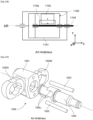
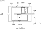
- FIGS. 12A And 12B are perspective and schematic representations respectively of an impact wrench equipped with a Maurer-type “Twin Hammer” rebound impact mechanism.
- a Maurer 1200 type "Twin Hammer” rebounding impact mechanism is distinguished from a Maurer type “Single Hammer” rebounding impact mechanism by the implementation, in the cage 1201, of two striking elements 1202A, 1202B diametrically opposed and offset from each other, i.e. arranged on separate planes.
- the two striking elements 1202A, 1202B are rotated symmetrically relative to the output square 1204.
- impact wrenches with a rebounding impact mechanism whether pneumatic or electric, generate, through the presence of known impact mechanisms, a high level of vibrations perceived by the user.
- the proposed technique aims in particular to provide an effective solution to at least some of these different problems.
- an objective of the proposed technique is to optimize impact wrenches with an impact mechanism.
- the proposed technique aims, according to at least one embodiment, to provide an impact wrench with an impact mechanism which, during the impact phase in particular, reduces or even eliminates the level of vibrations perceived by the user of such a wrench.
- an objective of the proposed technique is, according to at least one embodiment, to provide such an impact wrench which is simple to design and/or simple to implement.
- Another objective of the proposed technique is, according to at least one embodiment, to provide such an impact wrench which is lightweight and/or compact.
- anti-vibration means having such a configuration makes it possible, for impact mechanisms fixed in translation along their axis of rotation and comprising a striking system generating a strike at most once per revolution thereof, to reduce, or even eliminate, at least during the impact phase, the level of vibrations perceived by the user at lower cost. This therefore results in a reduction in the risk of the occurrence of diseases, or of discomfort, caused by such vibrations and therefore by an improvement in the comfort of use of the screwing/unscrewing tool.
- striking element is in contact with said striking receiving surface of said at least one striking receiving element so as to generate said impact torque.
- anti-vibration means can be implemented in transverse engagement systems allowing, thanks to the rebound, more than one acceleration revolution between two impacts, and therefore more energy per impact, as can be the case in particular in “Maurer” type impact mechanisms.
- this configuration allows the striking system to be equally dynamically balanced during acceleration phases, followed between two successive impact phases, and rotation phases.
- the anti-vibration means make it possible to reduce, or even eliminate, the level of vibrations perceived by the user for all operating phases of the screwing/unscrewing tool and not only during the impact phase. This results in a general improvement in the comfort and experience of using such a screwing/unscrewing tool. As a result, the risk of diseases or discomfort caused by vibrations is further minimised.
- said striking system comprises at least three striking elements having identical cross-sections in a plane essentially perpendicular to said axis of rotation, and in that said at least three striking elements constitute said anti-vibration means.
- Such a counterweight constitutes a simple solution to implement, making it possible to reduce or even eliminate, during the impact phase, the level of vibrations perceived by the user at a lower cost. Furthermore, such counterweights can be attached, via appropriate fixing means, to existing impact mechanisms.
- said at least one counterweight arranged in the impact mechanism, said at least one counterweight being positioned at 180°, along the axis of rotation of the impact mechanism, from said at least one striking element and from said at least one striking receiving element.
- impact wrenches with impact mechanisms of the electric type or of the pneumatic type, are known, implementing various types of impact mechanisms generating a high level of vibrations perceived by the user.
- the proposed technique (detailed below) is intended to be implemented in impact wrenches whose impact mechanism has these two cumulative technical characteristics. In other words, these two technical characteristics constitute prerequisites for the proposed technique.
- the inventor of the present application has identified a new and inventive technique allowing, for the types of impact mechanisms satisfying the prerequisites cited above, to minimize, or even eliminate, the level of vibrations perceived by the user.
- Such a configuration makes it possible to eliminate all or part of the undesirable external forces generated by the impact mechanism. This results in a reduction, or even elimination, of the level of vibrations perceived by the user during the operation of an impact wrench conforming to the proposed technique.
- the inventor of the present application has therefore established that by positioning the center of gravity G of the mechanical system on the axis of rotation Z , acceleration a G of the mechanical system at this point is, upon impact, zero. This results in the suppression of the reaction force F and therefore by a reduction in the level of vibration perceived by the user. This reasoning applies to each level holding the mechanical system.
- the inventor of the present application has found that the portion M z of the moment of the portion of the housing retaining the retaining the mechanical system M along the axis Z is low, because it corresponds to the friction in the bearing, and therefore negligible.
- the inventor of the present application has therefore established that in order to reduce, or even eliminate, the level of vibrations perceived by the user, the reactions M x and M y , corresponding to the reactions of the moment M according to the axes X And Y respectively, must be reduced or even eliminated.
- the inventor of the present application has therefore established that by defining, upon impact, the axis of rotation Z as the main axis of inertia of the system, the inertia products J xz and J yz , and therefore the associated reactions M x and M y , are reduced or even eliminated.
- the inventor of the present application has found that the rotors of the motors, whether electric or pneumatic, have substantially symmetry along their respective axis of revolution and therefore the axis of rotation. Z .
- the rotor's center of gravity is initially positioned on, or near, the Z axis of rotation which itself constitutes a principal axis of inertia.
- each component of the impact mechanism must satisfy these two criteria, namely positioning the center of gravity of the impact mechanism on the axis of rotation of the latter and having the axis of rotation as a principal axis of inertia of the impact mechanism.
- FIGS. 1 to 3 are schematic representations of examples of Maurer-type rebound impact mechanisms according to a first embodiment of the proposed technique.
- the principle of this first embodiment consists in implementing, in the impact mechanism, one or more counterweights, forming the anti-vibration means, configured so that, during an impact, the center of gravity of the impact mechanism is substantially positioned on its axis of rotation, and that the axis of rotation of the impact mechanism is substantially one of its principal axes of inertia.
- the impact mechanism comprises at least one counterweight diametrically opposed, i.e. positioned at 180°, from the striking element, relative to the axis of rotation of the impact mechanism.
- the counterweight and the striking element are at least partially arranged in the same plane transverse to the axis of rotation of the impact mechanism (plane normal to this axis of rotation).
- FIG. 1 illustrates a first example of the first embodiment of the proposed technique applied to a rebounding impact mechanism of the “Maurer Single Hammer” type.
- the rebounding impact mechanism of the "Maurer Single Hammer” type 110 is furthermore mounted rotatably, by means of bearings 110 1 , inside the housing 100 of the impact wrench.
- the cage 111 of the rebounding impact mechanism of the “Maurer Single Hammer” type 110 is intended to be driven in rotation by a motor (not visible).
- the motor, the cage 111 and the output square 112 are coaxial along an AR rotation axis oriented along the Z axis of the reference frame.
- the cage 111 is equipped with a striking system comprising a striking element 111 2 having a striking surface intended to be brought into collision against a striking receiving surface belonging to a striking receiving element 112 1 carried by the output square 112.
- the rebounding impact mechanism of the “Maurer Single Hammer” type 110 comprises several counterweights 111 3 , 112 2 configured so that, during an impact, the center of gravity G 1 of the rebounding impact mechanism of the “Maurer Single Hammer” type 110 is positioned on its axis of rotation AR, and that the axis of rotation AR of the impact mechanism is one of its main axes of inertia Z.
- the cage 111 carries a first counterweight 111 3 configured to return, during an impact, the center of gravity of the cage 111 and of the striking element 111 2 to the axis of rotation AR and that this axis of rotation AR is one of its main axes of inertia.
- the first counterweight 111 3 is configured to cancel, by counterbalancing, the radial forces at the axis of rotation AR induced by the cage 111 and the striking element 111 2 , that is to say the forces oriented along the axes X, Y of the reference frame.
- the cage 111 alone, i.e. without the striking element 111 2 , has from its manufacture a center of gravity on the AR rotation axis and that this AR rotation axis is one of its main axes of inertia.
- This observation results in a simplification of the configuration of the first counterweight 111 3 , namely only bringing the center of gravity of the striking element 111 2 onto the AR rotation axis and that this AR rotation axis is one of its main axes of inertia.
- the output square 112 carries second counterweights 112 2 configured to return, during an impact, the center of gravity of the strike receiving element 112 1 to the AR rotation axis and that this AR rotation axis is one of its main axes of inertia.
- the second counterweights 112 2 are configured to cancel, by counterbalancing, the radial forces at the axis of rotation AR induced by the striking receiving element 112 1 , that is to say the forces oriented along the axes X, Y of the reference frame.
- the first counterweight 111 3 is positioned on the cage 111 opposite the striking element 111 2 and facing the latter.
- the dimensioning of the first counterweight 111 3 is a function of the dimensioning of the striking element 111 2 , and therefore of the radial forces at the axis of rotation AR induced by the latter.
- the second counterweights 112 2 are positioned on the output square 112 diametrically opposite the strike receiving element 112 1 .
- the dimensioning of the second counterweights 112 2 is a function of the dimensioning of the strike receiving element 112 1 , and therefore of the radial forces at the axis of rotation AR induced by the latter.
- FIG. 2 illustrates a second example of the first embodiment of the proposed technique applied to a rebounding impact mechanism of the “Maurer Single Hammer” type.
- This second example of realization differs from the first only by the configuration of the counterweights.
- the rebounding impact mechanism of the “Maurer Single Hammer” type 200 comprises a single counterweight 211 3 configured so that, during an impact, the center of gravity G 2 of the rebounding impact mechanism of the “Maurer Single Hammer” type 110 is positioned on its axis of rotation AR, and that the axis of rotation AR of the impact mechanism is one of its main axes of inertia Z.
- the single counterweight 211 3 is therefore configured to return, during an impact, the center of gravity of the striking element 211 2 and the striking receiving element 212 1 to the axis of rotation AR and that this axis of rotation AR is one of its main axes of inertia.
- the single counterweight 211 3 is therefore configured to cancel, by counterbalancing, the radial forces to the axis of rotation AR induced by the striking element 111 2 and the striking receiving element 212 1 , that is to say the forces oriented according to the axes X, Y of the reference frame.
- the single counterweight 211 3 is positioned on the cage 211 at 180° from the striking element 211 2 (and therefore from the striking receiving element 212 1 upon impact).
- the dimensioning of the single counterweight 211 3 is a function of the dimensioning of the striking element 211 2 and of the striking receiving element 112 1 , and therefore of the radial forces at the axis of rotation AR induced by them.
- FIG. 3 illustrates a second example of the first embodiment of the proposed technique applied to a rebounding impact mechanism of the “Maurer Twin Hammer” type.
- This third example of realization is distinguished from the first by the structure of the impact mechanism and by the configuration of the counterweights.
- a rebounding impact mechanism of the "Maurer Twin Hammer” type is distinguished from a rebounding impact mechanism of the "Maurer Single Hammer” type by the implementation of two striking elements diametrically opposed and offset from each other.
- the rebounding impact mechanism of the “Maurer Twin Hammer” type 310 arranged in a reference X, Y, Z, comprises a cage 311 inside which is mounted mobile in rotation, by means of a retaining portion 311 1 , an output square 312.
- the rebounding impact mechanism of the "Maurer Twin Hammer” type 310 is furthermore mounted rotatably, by means of bearings 310 1 , inside the housing 300 of the impact wrench.
- the cage 311 of the rebounding impact mechanism of the “Maurer Twin Hammer” type 310 is intended to be driven in rotation by a motor (not visible).
- the motor, the cage 311 and the output square 312 are coaxial along an AR rotation axis oriented along the Z axis of the reference frame.
- the cage 311 is equipped with a striking system comprising two striking elements 311 2A , 311 2B located at 180° from each other and arranged in different radial planes to the axis of rotation AR.
- Each striking element 311 2A , 311 2B has a striking surface intended to be brought into collision with a striking receiving surface belonging to a striking receiving element 312 1A , 312 1B respectively, carried by the output square 112
- the rebounding impact mechanism of the “Maurer Twin Hammer” type 310 comprises several counterweights 311 3A , 311 3B , 312 2A , 312 2B configured so that, during an impact, the center of gravity G 3 of the rebounding impact mechanism of the “Maurer Twin Hammer” type 310 is positioned on its axis of rotation AR, and that the axis of rotation AR of the impact mechanism is one of its principal axes of inertia Z.
- the cage 111 carries two first counterweights 311 2A , 311 2B configured to return, during an impact, the center of gravity of the striking elements 311 2A , 311 2B to the AR rotation axis and that this AR rotation axis is one of its main axes of inertia.
- the first counterweights 311 3A , 311 3B are configured to cancel, by counterbalancing, the radial forces at the AR rotation axis induced by the striking elements 311 2A , 311 2B , that is to say the forces oriented according to the X, Y axes of the reference frame.
- each striking element 311 2A , 311 2B is associated with a first counterweight 311 3A , 311 3B , integral with the cage 311, which is diametrically opposite it.
- the dimensioning of the first counterweights 311 3A , 311 3B is a function of the dimensioning of the striking elements 311 2A , 311 2B , and therefore of the radial forces at the axis of rotation AR induced by the latter.
- the output square 312 carries two second counterweights 312 2A , 312 2B configured to return, during an impact, the center of gravity of the strike receiving elements 312 1A , 312 1B to the AR rotation axis and that this AR rotation axis is one of its main axes of inertia.
- the second counterweights 312 1A , 312 1B are configured to cancel, by counterbalancing, the radial forces at the rotation axis AR induced by the striking receiving elements 312 1A , 312 18 , that is to say the forces oriented along the axes X, Y of the reference frame.
- each strike receiving element 312 1A , 312 1B is associated with a second counterweight 312 2A , 312 2B , integral with the output square 312 , which is diametrically opposite it.
- the dimensioning of the second counterweights 312 2A , 312 2B is a function of the dimensioning of the strike receiving elements 312 1A , 312 18 , and therefore of the radial forces at the axis of rotation AR induced by the latter.
- FIGS. 4 to 11 are representations of several examples of the implementation of an impact mechanism of the “Maurer” type according to a second embodiment of the proposed technique.
- the principle of this second embodiment of the proposed technique consists in proposing an impact mechanism comprising a striking system equipped with at least three striking elements, having identical cross-sections, arranged in such a way that, during impact in particular, the center of gravity of the impact mechanism is positioned on its axis of rotation, and that the axis of rotation of the impact mechanism is one of its main axes of inertia.
- the inventor of the present application has found that when striking elements have identical cross-sections, the inertia and relative mass of each striking element are only proportional to its thickness. This finding arises from the fact that, when arranged in the cage, the striking elements have the same radial position of their center of gravity at all times.
- This second embodiment is therefore based on obtaining anti-vibration means via a particular arrangement of at least three striking elements having identical cross-sections.
- this particular arrangement consists in positioning two lateral striking elements having identical thickness values, on either side, along the axis of rotation of the impact mechanism (i.e. along the axis of rotation of the impact mechanism), of a central striking element having a total thickness value equal to twice the thickness value of a lateral striking element.
- the at least one central striking element is diametrically opposed to the two lateral striking elements with respect to the axis of rotation of the impact mechanism.
- This second embodiment makes it possible to further reduce the level of vibrations perceived by the user. Indeed, this second embodiment makes it possible to reduce, or even eliminate, the level of vibrations perceived by the user during the different operating phases of the impact mechanism.
- the axis of rotation of the impact mechanism is permanently one of the main axes of inertia of the impact mechanism.
- the central striking element comprises several juxtaposed elementary central striking elements, at least two for example, the sum of the thickness of which along the axis of the elementary central striking elements defines the total thickness value.
- FIG 4 is a schematic representation of a first example of the second embodiment of the proposed technique applied to a “Maurer” type rebounding impact mechanism.
- the “Maurer” type rebounding impact mechanism 410 arranged in an X, Y, Z reference frame, comprises a cage 411 inside which is mounted mobile in rotation, by means of a retaining portion 411 1 , an output square 412.
- the rebounding impact mechanism of the “Maurer” type 410 is furthermore mounted to be rotatable, by means of bearings 410 1 , inside the casing 400 of the impact wrench.
- the cage 411 of the mechanism 410 is intended to be driven in rotation by a motor (not visible).
- the motor, the cage 411 and the output square 412 are coaxial along an axis of rotation AR oriented along the Z axis of the reference frame.
- the impact mechanism 410 carries three striking elements 411 2A , 411 2B , 411 2C , having identical cross sections, arranged so that the center of gravity G 4 of the impact mechanism 410 is positioned on its axis of rotation AR, and that the axis of rotation AR of the impact mechanism is one of its main axes of inertia.
- the impact mechanism 410 has two identical lateral striking elements 411 2A , 411 2C arranged, along the axis of rotation AR of the impact mechanism, on either side of a central striking element 411 2B consisting of a single elementary central striking element.
- the three striking elements 411 2A , 411 2B , 411 2C are arranged in three distinct planes radial to the AR axis of rotation.
- central striking element 411 2B is 180° opposite the two lateral striking elements 411 2A , 411 2C relative to the AR axis of rotation of the impact mechanism.
- each lateral striking element 411 2A , 411 2C has a first thickness value e.
- the central striking element 411 2B has a second thickness value 2e.
- the second thickness value 2e is equal to twice the first thickness value e.
- the output square 412 carries three strike receiving elements 412 1A , 412 1B , 412 1C configured to cooperate with the three strike elements 411 2A , 411 2B , 411 2C respectively.
- FIG 5 is a perspective view of a model of a rebounding impact mechanism of the “Maurer” type according to the first example of the second embodiment described in relation to the figure 4 .
- FIG 6 is a longitudinal sectional view of the modeling of a “Maurer” type rebounding impact mechanism of the figure 5 .
- FIG. 7 illustrates a second example of the second embodiment of the proposed technique applied to a “Maurer” type rebounding impact mechanism.
- This second example of realization is distinguished from the first by the number and structure of the striking elements.
- the impact mechanism 710 comprises four striking elements 711 2A to 711 2D having identical cross sections and thickness values.
- two elementary lateral striking elements 711 2A , 711 2D are positioned juxtaposed, on either side, along the axis of rotation AR of the impact mechanism, of a central striking element consisting of two elementary central striking elements 711 2B , 711 2C .
- the four striking elements 711 2A to 711 2D having an identical thickness value, the total thickness value of the central striking elements 711 2A , 711 2D is therefore indeed equal to twice the thickness value of each lateral striking element 711 2A , 711 2D .
- the implementation of four identical striking elements 711 2A to 711 2D makes it possible to minimize the manufacturing costs of an impact wrench conforming to the proposed technique.
- FIG 8 illustrates a third example of the second embodiment of the proposed technique applied to a “Maurer” type rebounding impact mechanism.
- This third example of realization is distinguished from the first by the number and structure of the striking elements.
- the principle of the second embodiment of the proposed technique is satisfied and allows the center of gravity G of the impact mechanism to be positioned on its axis of rotation, and that the axis of rotation of the impact mechanism is one of its principal axes of inertia.
- the proposed technique is not intended to be applied to impact wrenches comprising impact mechanisms having components that move in translation along the axis of rotation of the output square, such as "Pin Clutch” or “Two Jaws” type mechanisms in particular.
- the proposed technique is also not intended to be applied to impact wrenches comprising impact mechanisms generating an impact more than once per revolution of the output square, such as the "Double Rocking Dog” type mechanism, for example, which rotates only half a revolution of the output square between each impact.
- the proposed technique is nevertheless intended to be applied to impact wrenches using “Maurer Single Hammer”, “Maurer Twin Hammer”, “Single Rocking Dog” mechanisms.
- the proposed technique was described and illustrated by retaining a theoretical modeling of the different components constituting the impact wrench: non-deformable bodies, non-existent play in the connections, etc.
- This theoretical modeling makes it possible to eliminate the vibrations perceived by the user by proposing an impact mechanism configured so that, at least during the impact, its center of gravity G is positioned on its axis of rotation, and that the axis of rotation is one of its main axes of inertia.
- the person skilled in the art will of course be able to adapt the shapes, dimensions and materials of the components of the impact mechanism, such as the output square, the hammer(s), the counterweight(s) in particular, to make it compliant with the proposed technique.
Landscapes
- Engineering & Computer Science (AREA)
- Mechanical Engineering (AREA)
- Percussive Tools And Related Accessories (AREA)
Claims (8)
- Schraub/Abschraubwerkzeug, das umfasst:- einen Antriebsmotor- einen zurückprallenden Schlagmechanismus vom Typ Maurer (110, 200, 310, 410, 810), der durch den Motor entlang einer Drehachse (AR) angetrieben wird und entlang der Drehachse (AR) translatorisch fest gehalten wird, wobei der Schlagmechanismus (110, 200, 310, 410, 710, 810) umfasst:- ein Schlagsystem, das entlang der Drehachse (AR) drehbar angetrieben wird und mindestens ein Schlagelement (1112, 2112, 3112A-B, 4112A-C, 7112A-D, 8112A-E) umfasst,- ein Abtriebsvierkant (112, 312, 412), das mindestens ein Schlagaufnahmeelement (1121, 2121, 3121A-B, 4121A-C) umfasst,wobei das mindestens eine Schlagelement (1112, 2112, 3112A-B, 4112A-C, 7112A-D, 8112A-E) dazu ausgestaltet ist, mit dem mindestens einen Schlagaufnahmeelement (1121, 2121, 3121A-B, 4121A-C) in Berührung zu gelangen, um ein Schlagmoment zu erzeugen,wobei das Schlagsystem dazu ausgestaltet ist, vor dem Schlag über mindestens 200° drehbar entlang der Drehachse (AR) angetrieben zu werden,dadurch gekennzeichnet, dass der Schlagmechanismus (110, 200, 310, 410, 810) Antivibrationsmittel umfasst, die derart ausgestaltet sind, dass zumindest bei einem Schlag:- der Schwerpunkt (G1, G2, G4, G3, G7) des Schlagmechanismus (110, 200, 310, 410, 710, 810) im Wesentlichen auf der Drehachse (AR) positioniert ist, und- die Drehachse (AR) des Schlagmechanismus (110, 200, 310, 410, 710, 810) im Wesentlichen eine seiner Hauptträgheitsachsen ist.
- Schraub/Abschraubwerkzeug nach Anspruch 1, dadurch gekennzeichnet, dass das mindestens eine Schlagelement (1112, 2112, 3112A-B, 4112A-C, 7112A-D, 8112A-E) eine Schlagfläche umfasst, und dadurch, dass das mindestens eine Schlagaufnahmeelement (1121, 2121, 3121A-B, 4121A-C) eine Schlagaufnahmefläche umfasst, und
dadurch, dass das mindestens eine Schlagelement (1112, 2112, 3112A-B, 4112A-C, 7112A-D, 8112A-E) dazu ausgestaltet ist, auf zyklische Weise abzuwechseln zwischen:- einer außer Eingriff gebrachten Position, in der das mindestens eine Schlagelement (1112, 2112, 3112A-B, 4112A-C, 7112A-D, 8112A-E) nicht mit dem mindestens einen Schlagaufnahmeelement (1121, 2121, 3121A-B, 4121A-C) in Berührung ist, und- einer in Eingriff gebrachten Position, in der die Schlagfläche des mindestens einen Schlagelements (1112, 2112, 3112A-B, 4112A-C, 7112A-D, 8112A-E) mit der Schlagaufnahmefläche des mindestens einen Schlagaufnahmeelements (1121, 2121, 3121A-B, 4121A-C) in Berührung ist, derart dass das Schlagmoment erzeugt wird. - Schraub/Abschraubwerkzeug nach einem der Ansprüche 1 und 2, dadurch gekennzeichnet, dass die Antivibrationsmittel derart ausgestaltet sind, dass:- der Schwerpunkt (G1, G2, G4, G3, G7) des Schlagmechanismus ständig im Wesentlichen auf seiner Drehachse (AR) positioniert ist, und- die Drehachse (AR) des Schlagmechanismus ständig im Wesentlichen eine seiner Hauptträgheitsachsen ist.
- Schraub/Abschraubwerkzeug nach Anspruch 3, dadurch gekennzeichnet, dass das Schlagsystem mindestens drei Schlagelemente (1112, 2112, 3112A-B, 4112A-C, 7112A-D, 8112A-E) umfasst, die in einer Ebene, die im Wesentlichen senkrecht zur Drehachse (AR) ist, identische Querschnitte aufweisen, und dadurch, dass die mindestens drei Schlagelemente (1112, 2112, 3112A-B, 4112A-C, 7112A-D, 8112A-E) die Antivibrationsmittel bilden.
- Schraub/Abschraubwerkzeug nach Anspruch 4, dadurch gekennzeichnet, dass das Schlagsystem entlang der Drehachse (AR) des Schlagmechanismus angeordnet Folgendes umfasst:- ein mittleres Schlagelement (4112B, 7112B-C, 8112B-D), das entlang der Drehachse (AR) des Schlagmechanismus (110, 200, 310, 410, 710, 810) einen Gesamtdickenwert (2e) aufweist, und- zwei seitliche Schlagelemente (4112A, 4112C, 7112A,D, 8112A,E), die auf beiden Seiten des mindestens einen mittleren Schlagelements (4112B, 7112B-C, 8112B-D) entlang der Drehachse (AR) des Schlagmechanismus (110, 200, 310, 410, 710, 810) angeordnet sind, wobei die seitlichen Schlagelemente (4112A, 4112C, 7112A,D, 8112A,E) jeweils einen Dickenwert (e) aufweisen, der gleich der Hälfte des Gesamtdickenwerts (2e) des mindestens einen mittleren Schlagelements (4112B, 7112B-C, 8112B-D) entlang der Drehachse (AR) ist, und dadurch, dass das mindestens eine mittlere Schlagelement (4112B, 7112B-C, 8112B-D) auf in Bezug auf die Drehachse (AR) des Schlagmechanismus (110, 200, 310, 410, 710, 810) diametral entgegengesetzte Weise zu den seitlichen Schlagelementen (4112A, 4112C, 7112A,D, 8112A,E) angeordnet ist.
- Schraub/Abschraubwerkzeug nach Anspruch 5, dadurch gekennzeichnet, dass das mittlere Schlagelement (4112B, 7112B-C, 8112B-D) mindestens zwei nebeneinanderliegende mittlere Elementarschlagelemente umfasst, wobei die Summe der Dicke entlang der Achse der mittleren Elementarschlagelemente gleich dem Gesamtdickenwert ist.
- Schraub/Abschraubwerkzeug nach Anspruch 1, dadurch gekennzeichnet, dass die Antivibrationsmittel mindestens ein Gegengewicht (1113, 1122, 2113, 3113A-B, 3122A-B) umfassen, das in dem Schlagmechanismus (110, 200, 310, 410, 710, 810) angeordnet ist, wobei das mindestens eine Gegengewicht (1113, 1122, 2113, 3113A-B, 3122A-B) dazu ausgestaltet ist, radialen Beanspruchungen an der Drehachse (AR), die durch das mindestens eine Schlagelement (1112, 2112, 3112A-B, 4112A-C, 7112A-D, 8112A-E) und durch das mindestens eine Schlagaufnahmeelement (1121, 2121, 3121A-B, 4121A-C) bewirkt werden, aufzuheben.
- Schraub/Abschraubwerkzeug nach Anspruch 7, dadurch gekennzeichnet, dass das mindestens eine Gegengewicht (1113, 1122, 2113, 3113A-B, 3122A-B) in dem Schlagmechanismus (110, 200, 310, 410, 710, 810) angeordnet ist, wobei das mindestens eine Gegengewicht (1113, 1122, 2113, 3113A-B, 3122A-B) in 180° entlang der Drehachse des Schlagmechanismus (110, 200, 310, 410, 710, 810) des mindestens einen Schlagelements (1112, 2112, 3112A-B, 4112A-C, 7112A-D, 8112A-E) und des mindestens einen Schlagaufnahmeelements (1121, 2121, 3121A-B, 4121A-C) positioniert ist.
Applications Claiming Priority (1)
| Application Number | Priority Date | Filing Date | Title |
|---|---|---|---|
| FR1915581A FR3105052B1 (fr) | 2019-12-24 | 2019-12-24 | Clé à choc à mécanisme d’impact |
Publications (2)
| Publication Number | Publication Date |
|---|---|
| EP3842184A1 EP3842184A1 (de) | 2021-06-30 |
| EP3842184B1 true EP3842184B1 (de) | 2024-10-23 |
Family
ID=70228191
Family Applications (1)
| Application Number | Title | Priority Date | Filing Date |
|---|---|---|---|
| EP20214371.5A Active EP3842184B1 (de) | 2019-12-24 | 2020-12-15 | Schlagschrauber mit aufprallmechanismus |
Country Status (3)
| Country | Link |
|---|---|
| US (1) | US11794316B2 (de) |
| EP (1) | EP3842184B1 (de) |
| FR (1) | FR3105052B1 (de) |
Families Citing this family (5)
| Publication number | Priority date | Publication date | Assignee | Title |
|---|---|---|---|---|
| FR3105052B1 (fr) * | 2019-12-24 | 2021-12-17 | Renault Georges Ets | Clé à choc à mécanisme d’impact |
| EP4212281A1 (de) * | 2021-10-27 | 2023-07-19 | Black & Decker Inc. | Mutterkanalzubehör für elektrowerkzeug |
| US12466037B2 (en) | 2021-10-27 | 2025-11-11 | Black & Decker Inc. | Nut runner accessory for power tool |
| US12521850B2 (en) | 2021-10-27 | 2026-01-13 | Black & Decker Inc. | Nut runner accessory for power tool |
| FR3131551B1 (fr) * | 2021-12-30 | 2024-02-09 | Renault Georges Ets | Procédé de réalisation d’une opération de vissage/dévissage comprenant une étape de détermination de la vitesse maximal de rebond du rotor |
Citations (1)
| Publication number | Priority date | Publication date | Assignee | Title |
|---|---|---|---|---|
| US20130264087A1 (en) * | 2010-12-28 | 2013-10-10 | Hitachi Koki Co., Ltd. | Driving Tool |
Family Cites Families (20)
| Publication number | Priority date | Publication date | Assignee | Title |
|---|---|---|---|---|
| US2285638A (en) * | 1939-11-22 | 1942-06-09 | Chicago Pneumatic Tool Co | Impact clutch |
| US2663395A (en) * | 1951-10-16 | 1953-12-22 | Reed Roller Bit Co | Impact hammer element |
| US3661217A (en) | 1970-07-07 | 1972-05-09 | Spencer B Maurer | Rotary impact tool and clutch therefor |
| US4287956A (en) | 1979-08-10 | 1981-09-08 | Maurer Spencer B | Impact wrench mechanism and pivot clutch |
| US4321973A (en) * | 1979-08-10 | 1982-03-30 | Maurer Spencer B | Rotary impact clutch |
| US5906244A (en) * | 1997-10-02 | 1999-05-25 | Ingersoll-Rand Company | Rotary impact tool with involute profile hammer |
| US6527061B2 (en) * | 2001-08-06 | 2003-03-04 | Hale Liao | Driving mechanism for pneumatic tools |
| US6782956B1 (en) * | 2003-03-07 | 2004-08-31 | Ingersoll-Rand Company | Drive system having an inertial valve |
| TWM308153U (en) * | 2006-08-24 | 2007-03-21 | Mobiletron Electronics Co Ltd | Punching spindle of electric tool |
| RU2534322C2 (ru) * | 2009-07-29 | 2014-11-27 | Хитачи Коки Ко., Лтд. | Импульсно-силовая ручная машина |
| TWM426477U (en) * | 2011-12-27 | 2012-04-11 | Hyphone Machine Ind Co Ltd | Striking block and striking tool head including the same |
| US20140069674A1 (en) * | 2012-09-07 | 2014-03-13 | Super Power Tools Co., Ltd. | Percussive hammer for pneumatic or electric tools |
| TW201406501A (zh) * | 2013-10-31 | 2014-02-16 | Quan-Zheng He | 氣動工具的衝擊組 |
| CN104608099B (zh) * | 2013-11-04 | 2017-04-19 | 南京德朔实业有限公司 | 一种输出扭矩的电动工具 |
| US9669526B2 (en) * | 2014-01-07 | 2017-06-06 | Ingersoll-Rand Company | Tools with socket retainers |
| US9539715B2 (en) * | 2014-01-16 | 2017-01-10 | Ingersoll-Rand Company | Controlled pivot impact tools |
| US20150343616A1 (en) * | 2014-06-03 | 2015-12-03 | Soartec Industrial Corp. | Hammering set for an impact tool |
| US20160214238A1 (en) * | 2015-01-23 | 2016-07-28 | Storm Pneumtic Tool Co., Ltd. | Pneumatic tool having an impact module with dual impact |
| CN110587550A (zh) * | 2018-06-12 | 2019-12-20 | 筌诚机械股份有限公司 | 用于动力工具冲击组件的冲击块以及与其配合的保持件 |
| FR3105052B1 (fr) * | 2019-12-24 | 2021-12-17 | Renault Georges Ets | Clé à choc à mécanisme d’impact |
-
2019
- 2019-12-24 FR FR1915581A patent/FR3105052B1/fr active Active
-
2020
- 2020-12-15 EP EP20214371.5A patent/EP3842184B1/de active Active
- 2020-12-22 US US17/130,620 patent/US11794316B2/en active Active
Patent Citations (1)
| Publication number | Priority date | Publication date | Assignee | Title |
|---|---|---|---|---|
| US20130264087A1 (en) * | 2010-12-28 | 2013-10-10 | Hitachi Koki Co., Ltd. | Driving Tool |
Also Published As
| Publication number | Publication date |
|---|---|
| EP3842184A1 (de) | 2021-06-30 |
| US11794316B2 (en) | 2023-10-24 |
| FR3105052A1 (fr) | 2021-06-25 |
| FR3105052B1 (fr) | 2021-12-17 |
| US20210187708A1 (en) | 2021-06-24 |
Similar Documents
| Publication | Publication Date | Title |
|---|---|---|
| EP3842184B1 (de) | Schlagschrauber mit aufprallmechanismus | |
| EP3908512B1 (de) | Elektrische unterstützungsvorrichtung für ein fahrrad | |
| WO2014199034A2 (fr) | Mecanisme d'articulation et siege de vehicule comportant un tel mecanisme | |
| WO2018002477A1 (fr) | Transmission, notamment pour engin roulant, et engin roulant équipe d'une telle transmission | |
| EP3365544B1 (de) | Wärmekraftmaschine mit system zur veränderung der verdichtung | |
| EP3667431A1 (de) | Mobile anzeigeeinheit einer uhr mit reibungsregulierungsmechanismus | |
| WO2021001636A1 (fr) | Siège d'aéronef | |
| EP3705949A1 (de) | Drehmomentbegrenzungsmechanismus eines uhrwerks | |
| EP3435173A1 (de) | Mechanisches uhrwerk mit sich drehendem isochronem resonator, der positionsunempfindlich ist | |
| EP1695907A1 (de) | Vorrichtung zur Verriegelung der Befestigungstruktur eines Blattes an der Nabe eines Drehflüglerrotors | |
| EP2951464B1 (de) | Vorrichtung zur unterdrückung von lageabweichungen in einem untersetzungsgetriebe mit einem umlaufenden rad | |
| EP0188164B1 (de) | Lenkungsblock für ein Kraftfahrzeug mit festem zentralem Kissen | |
| WO2020020656A1 (fr) | Poignée d'ouvrant de véhicule automobile munie d'un système de sécurité inertiel | |
| FR3033543A1 (fr) | Systeme de suspension antivibratoire d'une barre de maintien d'une boite de transmission de puissance d'aeronef, dispositif de suspension antivibratoire, et aeronef | |
| EP0366563B1 (de) | Selbstsperrendes Differential | |
| FR3067430B1 (fr) | Dispositif d'amortissement pendulaire | |
| FR2959291A1 (fr) | Differentiel autobloquant | |
| EP4296540B1 (de) | Mehrzwecksystem mit einem paar von mechanismen mit drehbaren exzentrischen elementen | |
| EP0600781A1 (de) | Verfahren zur Nachstellung und dynamischen Ausgleichens einer Übersetzungsvorrichtung | |
| EP1493945A1 (de) | Vorrichtung zum Umwandlen einer Winkelbewegung in einer linearen Bewegung | |
| CA2271093C (fr) | Moteur a combustion interne | |
| FR3143065A1 (fr) | Système de verrouillage /déverrouillage d’un actionneur à mouvement perdu d’inverseur de poussée et actionneur comportant un tel système | |
| CH612725A5 (en) | Hammer drill | |
| FR3141738A1 (fr) | Agencement pour l’entraînement d’une vis de reglage | |
| FR2742197A1 (fr) | Accouplement a liberation |
Legal Events
| Date | Code | Title | Description |
|---|---|---|---|
| PUAI | Public reference made under article 153(3) epc to a published international application that has entered the european phase |
Free format text: ORIGINAL CODE: 0009012 |
|
| STAA | Information on the status of an ep patent application or granted ep patent |
Free format text: STATUS: THE APPLICATION HAS BEEN PUBLISHED |
|
| AK | Designated contracting states |
Kind code of ref document: A1 Designated state(s): AL AT BE BG CH CY CZ DE DK EE ES FI FR GB GR HR HU IE IS IT LI LT LU LV MC MK MT NL NO PL PT RO RS SE SI SK SM TR |
|
| STAA | Information on the status of an ep patent application or granted ep patent |
Free format text: STATUS: REQUEST FOR EXAMINATION WAS MADE |
|
| 17P | Request for examination filed |
Effective date: 20210706 |
|
| RBV | Designated contracting states (corrected) |
Designated state(s): AL AT BE BG CH CY CZ DE DK EE ES FI FR GB GR HR HU IE IS IT LI LT LU LV MC MK MT NL NO PL PT RO RS SE SI SK SM TR |
|
| STAA | Information on the status of an ep patent application or granted ep patent |
Free format text: STATUS: EXAMINATION IS IN PROGRESS |
|
| 17Q | First examination report despatched |
Effective date: 20221017 |
|
| GRAP | Despatch of communication of intention to grant a patent |
Free format text: ORIGINAL CODE: EPIDOSNIGR1 |
|
| STAA | Information on the status of an ep patent application or granted ep patent |
Free format text: STATUS: GRANT OF PATENT IS INTENDED |
|
| INTG | Intention to grant announced |
Effective date: 20240116 |
|
| GRAS | Grant fee paid |
Free format text: ORIGINAL CODE: EPIDOSNIGR3 |
|
| GRAJ | Information related to disapproval of communication of intention to grant by the applicant or resumption of examination proceedings by the epo deleted |
Free format text: ORIGINAL CODE: EPIDOSDIGR1 |
|
| GRAL | Information related to payment of fee for publishing/printing deleted |
Free format text: ORIGINAL CODE: EPIDOSDIGR3 |
|
| STAA | Information on the status of an ep patent application or granted ep patent |
Free format text: STATUS: EXAMINATION IS IN PROGRESS |
|
| GRAP | Despatch of communication of intention to grant a patent |
Free format text: ORIGINAL CODE: EPIDOSNIGR1 |
|
| STAA | Information on the status of an ep patent application or granted ep patent |
Free format text: STATUS: GRANT OF PATENT IS INTENDED |
|
| INTC | Intention to grant announced (deleted) | ||
| INTG | Intention to grant announced |
Effective date: 20240422 |
|
| GRAS | Grant fee paid |
Free format text: ORIGINAL CODE: EPIDOSNIGR3 |
|
| GRAA | (expected) grant |
Free format text: ORIGINAL CODE: 0009210 |
|
| STAA | Information on the status of an ep patent application or granted ep patent |
Free format text: STATUS: THE PATENT HAS BEEN GRANTED |
|
| AK | Designated contracting states |
Kind code of ref document: B1 Designated state(s): AL AT BE BG CH CY CZ DE DK EE ES FI FR GB GR HR HU IE IS IT LI LT LU LV MC MK MT NL NO PL PT RO RS SE SI SK SM TR |
|
| REG | Reference to a national code |
Ref country code: GB Ref legal event code: FG4D Free format text: NOT ENGLISH |
|
| REG | Reference to a national code |
Ref country code: CH Ref legal event code: EP |
|
| REG | Reference to a national code |
Ref country code: DE Ref legal event code: R096 Ref document number: 602020039822 Country of ref document: DE |
|
| REG | Reference to a national code |
Ref country code: IE Ref legal event code: FG4D Free format text: LANGUAGE OF EP DOCUMENT: FRENCH |
|
| REG | Reference to a national code |
Ref country code: LT Ref legal event code: MG9D |
|
| REG | Reference to a national code |
Ref country code: NL Ref legal event code: MP Effective date: 20241023 |
|
| REG | Reference to a national code |
Ref country code: AT Ref legal event code: MK05 Ref document number: 1734472 Country of ref document: AT Kind code of ref document: T Effective date: 20241023 |
|
| PG25 | Lapsed in a contracting state [announced via postgrant information from national office to epo] |
Ref country code: NL Free format text: LAPSE BECAUSE OF FAILURE TO SUBMIT A TRANSLATION OF THE DESCRIPTION OR TO PAY THE FEE WITHIN THE PRESCRIBED TIME-LIMIT Effective date: 20241023 |
|
| PG25 | Lapsed in a contracting state [announced via postgrant information from national office to epo] |
Ref country code: NL Free format text: LAPSE BECAUSE OF FAILURE TO SUBMIT A TRANSLATION OF THE DESCRIPTION OR TO PAY THE FEE WITHIN THE PRESCRIBED TIME-LIMIT Effective date: 20241023 |
|
| PG25 | Lapsed in a contracting state [announced via postgrant information from national office to epo] |
Ref country code: IS Free format text: LAPSE BECAUSE OF FAILURE TO SUBMIT A TRANSLATION OF THE DESCRIPTION OR TO PAY THE FEE WITHIN THE PRESCRIBED TIME-LIMIT Effective date: 20250223 Ref country code: HR Free format text: LAPSE BECAUSE OF FAILURE TO SUBMIT A TRANSLATION OF THE DESCRIPTION OR TO PAY THE FEE WITHIN THE PRESCRIBED TIME-LIMIT Effective date: 20241023 Ref country code: PT Free format text: LAPSE BECAUSE OF FAILURE TO SUBMIT A TRANSLATION OF THE DESCRIPTION OR TO PAY THE FEE WITHIN THE PRESCRIBED TIME-LIMIT Effective date: 20250224 |
|
| PG25 | Lapsed in a contracting state [announced via postgrant information from national office to epo] |
Ref country code: FI Free format text: LAPSE BECAUSE OF FAILURE TO SUBMIT A TRANSLATION OF THE DESCRIPTION OR TO PAY THE FEE WITHIN THE PRESCRIBED TIME-LIMIT Effective date: 20241023 |
|
| PG25 | Lapsed in a contracting state [announced via postgrant information from national office to epo] |
Ref country code: BG Free format text: LAPSE BECAUSE OF FAILURE TO SUBMIT A TRANSLATION OF THE DESCRIPTION OR TO PAY THE FEE WITHIN THE PRESCRIBED TIME-LIMIT Effective date: 20241023 |
|
| PG25 | Lapsed in a contracting state [announced via postgrant information from national office to epo] |
Ref country code: ES Free format text: LAPSE BECAUSE OF FAILURE TO SUBMIT A TRANSLATION OF THE DESCRIPTION OR TO PAY THE FEE WITHIN THE PRESCRIBED TIME-LIMIT Effective date: 20241023 |
|
| PG25 | Lapsed in a contracting state [announced via postgrant information from national office to epo] |
Ref country code: NO Free format text: LAPSE BECAUSE OF FAILURE TO SUBMIT A TRANSLATION OF THE DESCRIPTION OR TO PAY THE FEE WITHIN THE PRESCRIBED TIME-LIMIT Effective date: 20250123 |
|
| PG25 | Lapsed in a contracting state [announced via postgrant information from national office to epo] |
Ref country code: AT Free format text: LAPSE BECAUSE OF FAILURE TO SUBMIT A TRANSLATION OF THE DESCRIPTION OR TO PAY THE FEE WITHIN THE PRESCRIBED TIME-LIMIT Effective date: 20241023 Ref country code: LV Free format text: LAPSE BECAUSE OF FAILURE TO SUBMIT A TRANSLATION OF THE DESCRIPTION OR TO PAY THE FEE WITHIN THE PRESCRIBED TIME-LIMIT Effective date: 20241023 Ref country code: GR Free format text: LAPSE BECAUSE OF FAILURE TO SUBMIT A TRANSLATION OF THE DESCRIPTION OR TO PAY THE FEE WITHIN THE PRESCRIBED TIME-LIMIT Effective date: 20250124 |
|
| PG25 | Lapsed in a contracting state [announced via postgrant information from national office to epo] |
Ref country code: PL Free format text: LAPSE BECAUSE OF FAILURE TO SUBMIT A TRANSLATION OF THE DESCRIPTION OR TO PAY THE FEE WITHIN THE PRESCRIBED TIME-LIMIT Effective date: 20241023 |
|
| PG25 | Lapsed in a contracting state [announced via postgrant information from national office to epo] |
Ref country code: RS Free format text: LAPSE BECAUSE OF FAILURE TO SUBMIT A TRANSLATION OF THE DESCRIPTION OR TO PAY THE FEE WITHIN THE PRESCRIBED TIME-LIMIT Effective date: 20250123 |
|
| PG25 | Lapsed in a contracting state [announced via postgrant information from national office to epo] |
Ref country code: SM Free format text: LAPSE BECAUSE OF FAILURE TO SUBMIT A TRANSLATION OF THE DESCRIPTION OR TO PAY THE FEE WITHIN THE PRESCRIBED TIME-LIMIT Effective date: 20241023 |
|
| PG25 | Lapsed in a contracting state [announced via postgrant information from national office to epo] |
Ref country code: MC Free format text: LAPSE BECAUSE OF FAILURE TO SUBMIT A TRANSLATION OF THE DESCRIPTION OR TO PAY THE FEE WITHIN THE PRESCRIBED TIME-LIMIT Effective date: 20241023 |
|
| PG25 | Lapsed in a contracting state [announced via postgrant information from national office to epo] |
Ref country code: DK Free format text: LAPSE BECAUSE OF FAILURE TO SUBMIT A TRANSLATION OF THE DESCRIPTION OR TO PAY THE FEE WITHIN THE PRESCRIBED TIME-LIMIT Effective date: 20241023 |
|
| PG25 | Lapsed in a contracting state [announced via postgrant information from national office to epo] |
Ref country code: EE Free format text: LAPSE BECAUSE OF FAILURE TO SUBMIT A TRANSLATION OF THE DESCRIPTION OR TO PAY THE FEE WITHIN THE PRESCRIBED TIME-LIMIT Effective date: 20241023 |
|
| PG25 | Lapsed in a contracting state [announced via postgrant information from national office to epo] |
Ref country code: RO Free format text: LAPSE BECAUSE OF FAILURE TO SUBMIT A TRANSLATION OF THE DESCRIPTION OR TO PAY THE FEE WITHIN THE PRESCRIBED TIME-LIMIT Effective date: 20241023 |
|
| REG | Reference to a national code |
Ref country code: DE Ref legal event code: R097 Ref document number: 602020039822 Country of ref document: DE |
|
| PG25 | Lapsed in a contracting state [announced via postgrant information from national office to epo] |
Ref country code: SK Free format text: LAPSE BECAUSE OF FAILURE TO SUBMIT A TRANSLATION OF THE DESCRIPTION OR TO PAY THE FEE WITHIN THE PRESCRIBED TIME-LIMIT Effective date: 20241023 |
|
| PG25 | Lapsed in a contracting state [announced via postgrant information from national office to epo] |
Ref country code: CZ Free format text: LAPSE BECAUSE OF FAILURE TO SUBMIT A TRANSLATION OF THE DESCRIPTION OR TO PAY THE FEE WITHIN THE PRESCRIBED TIME-LIMIT Effective date: 20241023 |
|
| PG25 | Lapsed in a contracting state [announced via postgrant information from national office to epo] |
Ref country code: IT Free format text: LAPSE BECAUSE OF FAILURE TO SUBMIT A TRANSLATION OF THE DESCRIPTION OR TO PAY THE FEE WITHIN THE PRESCRIBED TIME-LIMIT Effective date: 20241023 |
|
| REG | Reference to a national code |
Ref country code: CH Ref legal event code: PL |
|
| PG25 | Lapsed in a contracting state [announced via postgrant information from national office to epo] |
Ref country code: LU Free format text: LAPSE BECAUSE OF NON-PAYMENT OF DUE FEES Effective date: 20241215 |
|
| PLBE | No opposition filed within time limit |
Free format text: ORIGINAL CODE: 0009261 |
|
| STAA | Information on the status of an ep patent application or granted ep patent |
Free format text: STATUS: NO OPPOSITION FILED WITHIN TIME LIMIT |
|
| PG25 | Lapsed in a contracting state [announced via postgrant information from national office to epo] |
Ref country code: SE Free format text: LAPSE BECAUSE OF FAILURE TO SUBMIT A TRANSLATION OF THE DESCRIPTION OR TO PAY THE FEE WITHIN THE PRESCRIBED TIME-LIMIT Effective date: 20241023 |
|
| 26N | No opposition filed |
Effective date: 20250724 |
|
| REG | Reference to a national code |
Ref country code: BE Ref legal event code: MM Effective date: 20241231 |
|
| PG25 | Lapsed in a contracting state [announced via postgrant information from national office to epo] |
Ref country code: BE Free format text: LAPSE BECAUSE OF NON-PAYMENT OF DUE FEES Effective date: 20241231 |
|
| PG25 | Lapsed in a contracting state [announced via postgrant information from national office to epo] |
Ref country code: CH Free format text: LAPSE BECAUSE OF NON-PAYMENT OF DUE FEES Effective date: 20241231 |
|
| PG25 | Lapsed in a contracting state [announced via postgrant information from national office to epo] |
Ref country code: IE Free format text: LAPSE BECAUSE OF NON-PAYMENT OF DUE FEES Effective date: 20241215 |
|
| PGFP | Annual fee paid to national office [announced via postgrant information from national office to epo] |
Ref country code: DE Payment date: 20251219 Year of fee payment: 6 |
|
| PGFP | Annual fee paid to national office [announced via postgrant information from national office to epo] |
Ref country code: GB Payment date: 20251224 Year of fee payment: 6 |
|
| PGFP | Annual fee paid to national office [announced via postgrant information from national office to epo] |
Ref country code: FR Payment date: 20251218 Year of fee payment: 6 |