EP3842358B1 - Abdeckvorrichtung zur befestigung an einem hals eines behälters - Google Patents
Abdeckvorrichtung zur befestigung an einem hals eines behälters Download PDFInfo
- Publication number
- EP3842358B1 EP3842358B1 EP20383111.0A EP20383111A EP3842358B1 EP 3842358 B1 EP3842358 B1 EP 3842358B1 EP 20383111 A EP20383111 A EP 20383111A EP 3842358 B1 EP3842358 B1 EP 3842358B1
- Authority
- EP
- European Patent Office
- Prior art keywords
- cap
- ring
- neck
- capping device
- fixing element
- Prior art date
- Legal status (The legal status is an assumption and is not a legal conclusion. Google has not performed a legal analysis and makes no representation as to the accuracy of the status listed.)
- Active
Links
Images



Classifications
-
- B—PERFORMING OPERATIONS; TRANSPORTING
- B65—CONVEYING; PACKING; STORING; HANDLING THIN OR FILAMENTARY MATERIAL
- B65D—CONTAINERS FOR STORAGE OR TRANSPORT OF ARTICLES OR MATERIALS, e.g. BAGS, BARRELS, BOTTLES, BOXES, CANS, CARTONS, CRATES, DRUMS, JARS, TANKS, HOPPERS, FORWARDING CONTAINERS; ACCESSORIES, CLOSURES, OR FITTINGS THEREFOR; PACKAGING ELEMENTS; PACKAGES
- B65D47/00—Closures with filling and discharging, or with discharging, devices
- B65D47/04—Closures with discharging devices other than pumps
- B65D47/06—Closures with discharging devices other than pumps with pouring spouts or tubes; with discharge nozzles or passages
- B65D47/08—Closures with discharging devices other than pumps with pouring spouts or tubes; with discharge nozzles or passages having articulated or hinged closures
- B65D47/0857—Closures with discharging devices other than pumps with pouring spouts or tubes; with discharge nozzles or passages having articulated or hinged closures made separately from the base element provided with the spout or discharge passage
- B65D47/0876—Hinges without elastic bias
- B65D47/088—Hinges without elastic bias located at an edge of the base element
- B65D47/0885—Hinges without elastic bias located at an edge of the base element one part of the hinge being integral with the hinged closure and the other part with the base element, without any other additional hinge element
-
- B—PERFORMING OPERATIONS; TRANSPORTING
- B65—CONVEYING; PACKING; STORING; HANDLING THIN OR FILAMENTARY MATERIAL
- B65D—CONTAINERS FOR STORAGE OR TRANSPORT OF ARTICLES OR MATERIALS, e.g. BAGS, BARRELS, BOTTLES, BOXES, CANS, CARTONS, CRATES, DRUMS, JARS, TANKS, HOPPERS, FORWARDING CONTAINERS; ACCESSORIES, CLOSURES, OR FITTINGS THEREFOR; PACKAGING ELEMENTS; PACKAGES
- B65D41/00—Caps, e.g. crown caps or crown seals, i.e. members having parts arranged for engagement with the external periphery of a neck or wall defining a pouring opening or discharge aperture; Protective cap-like covers for closure members, e.g. decorative covers of metal foil or paper
- B65D41/32—Caps or cap-like covers with lines of weakness, tearing-strips, tags, or like opening or removal devices, e.g. to facilitate formation of pouring openings
- B65D41/34—Threaded or like caps or cap-like covers provided with tamper elements formed in, or attached to, the closure skirt
- B65D41/3442—Threaded or like caps or cap-like covers provided with tamper elements formed in, or attached to, the closure skirt with rigid bead or projections formed on the tamper element and coacting with bead or projections on the container
- B65D41/3447—Threaded or like caps or cap-like covers provided with tamper elements formed in, or attached to, the closure skirt with rigid bead or projections formed on the tamper element and coacting with bead or projections on the container the tamper element being integrally connected to the closure by means of bridges
-
- B—PERFORMING OPERATIONS; TRANSPORTING
- B65—CONVEYING; PACKING; STORING; HANDLING THIN OR FILAMENTARY MATERIAL
- B65D—CONTAINERS FOR STORAGE OR TRANSPORT OF ARTICLES OR MATERIALS, e.g. BAGS, BARRELS, BOTTLES, BOXES, CANS, CARTONS, CRATES, DRUMS, JARS, TANKS, HOPPERS, FORWARDING CONTAINERS; ACCESSORIES, CLOSURES, OR FITTINGS THEREFOR; PACKAGING ELEMENTS; PACKAGES
- B65D55/00—Accessories for container closures not otherwise provided for
- B65D55/16—Devices preventing loss of removable closure members
-
- B—PERFORMING OPERATIONS; TRANSPORTING
- B65—CONVEYING; PACKING; STORING; HANDLING THIN OR FILAMENTARY MATERIAL
- B65D—CONTAINERS FOR STORAGE OR TRANSPORT OF ARTICLES OR MATERIALS, e.g. BAGS, BARRELS, BOTTLES, BOXES, CANS, CARTONS, CRATES, DRUMS, JARS, TANKS, HOPPERS, FORWARDING CONTAINERS; ACCESSORIES, CLOSURES, OR FITTINGS THEREFOR; PACKAGING ELEMENTS; PACKAGES
- B65D2251/00—Details relating to container closures
- B65D2251/10—Details of hinged closures
- B65D2251/1008—Means for locking the closure in open position
-
- B—PERFORMING OPERATIONS; TRANSPORTING
- B65—CONVEYING; PACKING; STORING; HANDLING THIN OR FILAMENTARY MATERIAL
- B65D—CONTAINERS FOR STORAGE OR TRANSPORT OF ARTICLES OR MATERIALS, e.g. BAGS, BARRELS, BOTTLES, BOXES, CANS, CARTONS, CRATES, DRUMS, JARS, TANKS, HOPPERS, FORWARDING CONTAINERS; ACCESSORIES, CLOSURES, OR FITTINGS THEREFOR; PACKAGING ELEMENTS; PACKAGES
- B65D2401/00—Tamper-indicating means
- B65D2401/15—Tearable part of the closure
- B65D2401/30—Tamper-ring remaining connected to closure after initial removal
Definitions
- the invention relates to a device for capping a container and an assembly comprising a container equipped with such a capping device.
- the invention relates more particularly to a capping device that makes it possible to keep a cap attached to the neck of a container, thus avoiding losing the cap in nature.
- the capping device comprises a ring that is intended to be retained on the neck of the container, a cap that is intended to cover the orifice of the container to seal it, two elastic sheets that join the cap with the lower ring and a locking device installed to lock the cap in a tilted open position.
- capping device is not fully satisfactory.
- this cap is intended to snap fit into the neck of the container and cannot be adapted to other types of neck.
- the movement of the cap between the closed position and the tilted open position is a simple pivot movement, which limits the height of the cap and / or neck that can be used. This limits the applications of said capping device.
- it is not suitable for containers intended to receive carbonated beverages because the pressure inside such containers would lead to unwanted openings of the cap.
- the locking device is not adapted for all types of cap and does not ensure sufficient reliability to maintain the tilted open position in screw caps, for example.
- One idea on which the invention is based is to propose a capping device that allows keeping a cap attached to the neck of the container that is easy to manufacture and use and that allows the cap to be kept in the tilted open position in a reliable and robust manner.
- the invention provides a capping device, intended to be fixed to a neck of a container in order to seal an orifice of said neck, said neck comprising an engaging collar, the capping device comprising:
- the capping device makes it possible to propose a cap that can remain attached to the neck with the help of the ring and the articulation device.
- the articulation of the ring allows, for its part, to adapt the capping device to long necks, for example, for the use of a cap to be screwed on.
- the male fixing element and the female fixing element allow providing a robust locking device that adapts to any type of cap, for example, that is to be screwed or snap fit.
- the arrangement of the lug in the housing and its orientation relative to the heel allow the tilted open position to be robustly maintained.
- the relative position of the female fixing element with respect to the articulation device is constant, which makes it possible to ensure a precise positioning of the male fixing element with respect to the female fixing element. during the pivoting of the cap towards its tilted open position.
- a capping device of this type may comprise one or more of the following features.
- the housing comprises a beveled lower part that forms said lower surface.
- the lug and the heel extend parallel to the axis of rotation.
- the lug and the heel thus form a snap-fit connection made in the same direction as the axis of rotation, thus, it is referred to as a horizontal snap-fit.
- a horizontal snap-fit Unlike a vertical snap fit, for example, such a snap fit allows for a better grip in the tilted open position due to its orientation relative to the kinematics of the cap. Otherwise, because the snap-fit extends in this direction, the grip is further improved.
- the male fixing element comprises a main portion connecting the lug to the outer peripheral skirt of the cap, the lug and the main portion being inclined relative to each other to form a hook.
- the hook shape of the male fixing element allows better retention in the housing of the female fixing element when the cap is in the tilted open position.
- the capping device is made by molding with the help of two half-shells that are joined at the level of a radial joint plane, the male fixing element of the cap and the female fixing element of the ring being made each one on both sides of said joint plan.
- the design of the capping device allows an unmolding with a mold with two half-shells without leaving any residues.
- the joint plane is oriented to pass through a central axis X of the capping device and through the center of the articulation device.
- the male fixing element of the cap is formed in line and centered above the articulation device.
- the female fixing element of the ring is formed in line and centered below the articulation device.
- the articulation device comprises a deformable sheet connecting the outer peripheral skirt and the second section of the ring.
- the deformable sheet has the function of a hinge by elastic deformation thereof during the movement of the cap from the released position towards the tilted open position.
- the deformable sheet comprises a predetermined pivot area configured so that the axis of rotation of the capping device is located in this predetermined pivot area.
- the predetermined pivot area is made with the aid of a zigzag portion of the deformable sheet.
- the first section and the second section are separated from each other by two thin areas in which the ring locally has a radial thickness decrease to allow the second section to articulate with respect to the first section.
- the ring is intended to be mounted movably in rotation on the neck around a central axis X of the capping device and the outer peripheral skirt of the cap has a helical thread intended to cooperate with a helical thread provided on the neck of the container to allow screwing or unscrewing of the cap on the neck around the central axis X.
- the ring comprises a notch configured to locally deflect the ring from the engaging collar, the notch being diametrically opposite to the articulation device
- the cap comprises a closing element that protrudes axially from the outer peripheral skirt and that it is diametrically opposite to the articulation device, the closing element being intended to cooperate with the engaging collar provided on the neck to position the closing element in the notch and to keep the cap in the closed position.
- the lower ring is connected to the outer peripheral skirt by frangible bridges.
- the second section extends over the entire height of the ring.
- the second section extends over an angular range comprised between 120 and 200°, and preferably comprised between 160 and 190°.
- the articulation device is connected to the second section in a central area of the second section.
- the capping device is made by molding in a single piece.
- the invention also provides an assembly comprising a container equipped with a neck comprising a engaging collar and an orifice, and equipped with a capping device mentioned above, the first section of the ring of the capping device being retained axially into the engaging collar of the neck.
- the first section comprises one or more retaining elements that project radially towards the interior of the ring; they are arranged below the engaging collar and are configured to axially retain the ring on the neck of the container.
- the housing is delimited downwards by a lower surface against which the lug is intended to be supported during the movement of the cap towards the tilted open position, which makes it possible to exert a downwardly directed force on the ring and which allows the second section of the ring to be brought back to the lowered position where it is aligned with the first section.
- the X axis corresponds to a central axis of the capping device intended to be positioned orthogonally to the plane of the orifice to be sealed when the capping device is in the closing position and seals said orifice.
- the X axis thus corresponds to the axis of rotation of the cap of the capping device when it is screwed onto the neck of the container.
- the "radial” orientation is orthogonal to the X axis.
- the terms "external” and “internal” are used to define the relative position of an element with respect to another, by reference to the X axis, an element close to the X axis is thus qualified as internal as opposed to an external element located radially on the periphery.
- upper and lower are used to define the relative position of one element with respect to another by reference to a position in which the orifice in the neck is directed upwards and the cap is in a closed position on the neck of the container, an element intended to be positioned lower being designated as lower element and an element intended to be positioned higher being designated as upper element.
- the capping device 1 is intended to be assembled on the neck 2 or throat of a container, as shown in Figures 1 to 4 .
- the container is, for example, a bottle.
- the capping device 1 comprises a so-called tamper-evident ring 3 that is intended to be retained on the neck 2 of the container, a cap 4 that is intended to cover the orifice 5 of the container to seal it and an articulation device 6 that joins the cap 4 with the lower ring 3. Furthermore, the capping device 1 also comprises a locking device composed of a male fixing element 7a formed in the cap 4 and a female fixing element 7b formed in the ring 3, the locking device 7a, 7b being arranged to lock the cap 4 in a tilted open position, shown in Figures 3 and 4 , wherein the cap 4 is disengaged from the orifice 5 of the container and does not hinder the pouring of the contents of the container.
- the capping device 1 is made by molding with the help of two half-shells that are joined at the level of a joint plane, as well as a mold that is placed on top of the half-shells.
- the half-shells make it possible to mold, in particular, the peripheral skirt 9 and the ring 3, while the mold allows the upper wall 8 of the capping device 1 to be molded.
- the joint plane is oriented to pass through the X axis of the capping device 1 and through the center of the articulation device 6.
- the ring 3 is held axially in the neck 2 of the container by means of an engaging collar 18, in particular, represented in Figures 1 to 3 .
- the engaging collar 18 has a frusto-conical external surface that tapers upwards, that is, in direction of the orifice 5 of the container.
- the engaging collar 18 delimits, downwards, that is, in a direction opposite to the orifice 5, a projection.
- the cap 4 comprises an upper wall 8 intended to be arranged substantially orthogonal to the axis X, opposite the orifice 5 of the neck 2 when said cap 4 is in the closed position.
- the cap 4 further comprises an outer peripheral skirt 9 intended to surround the neck 2 of the container when the cap 4 is in the closed position.
- the outer peripheral skirt 9 extends, downward, perpendicular to the upper wall 8, from the outer periphery of said upper wall 8.
- the outer peripheral skirt 9 has, on its internal face, a thread 10 formed by a series of helical ribs and intended to cooperate with a complementary thread 11, that is visible, specifically, in Figures 2 and 3 , formed by a series of helical ribs, and provided on the external surface of the neck 2.
- the cap 4 is suitable to be screwed onto neck 2 in order to close the container and to be unscrewed from the neck 2 in order to open the container.
- the cap 4 is thus movable between the closing position, represented in figure 1 , and a released position, represented in figure 2 . In said released position, the cap 4 is no longer inside the neck 2 of the container. In this way it is suitable to be tilted towards the open tilted position, shown in Figures 3 and 4 , wherein the cap 4 is released from the orifice 5 of the neck 2 so as not to hinder the pouring of the contents of the container.
- the cap 4 is not screwed onto the neck 2, but is snap fit onto it.
- Ring 3 comprises a notch configured to locally deflect the ring 3 from the engaging collar 18.
- the notch is diametrically opposite to the articulation device 6.
- the cap 4 comprises a closing element which projects axially from the outer peripheral skirt 9 and which is also diametrically opposite to the articulation device to be in line with the notch in the closed position.
- the closing element comprises a projection directed towards the inside of the cap 4 at one end of the closing element and which is intended to cooperate with the engaging collar 18 provided on the neck 2 to position the closing element in the notch and to maintain the cap 4 in closed position.
- the projection generates the elastic deformation of the closing element to return to its initial state after having passed the engaging collar 18 and thus maintain the cap 4 with respect to the neck 2 in the closed position in the form of a snap-fit connection.
- the outer peripheral skirt 9 has, on its outer face, a series of grooves distributed around the X axis and extending parallel to said X axis.
- the grooves thus provide a rough surface that facilitates the grip of the cap 4 by the user or by the assembly device of the bottling chain.
- the cap 4 also comprises an internal skirt 12, represented in particular in Figure 4 , which extends perpendicularly downward from the upper wall 8 of the cap 4 and is sized to be inserted inside the orifice 5 of the neck 2.
- the cap 4 also comprises an annular lip 13, also visible in figure 4 , which extends, from the upper wall 8, radially between the inner skirt 12 and the outer peripheral skirt 9.
- the inner skirt 12 and the annular lip 13 are sized in such a way that, when the cap 4 is in the closed position, on the neck 2 of the container, the inner skirt 12 is in contact against the inner face of the neck 2, while the annular lip 13 is in contact against the outer face neck 2. In this way, the inner skirt 12 and the annular lip 13 make it possible to ensure the sealing of the closure.
- the ring 3 is connected, before the first opening of the container, to the cap 4 by frangible bridges 14, visible in Figure 1 , intended to break during the first opening of the cap 4.
- frangible bridges 14 constitute, in this way, tamper-evident signs, hence the term tamper-evident ring 3. More particularly, the frangible bridges 14 are distributed around the axis X and connect the upper edge of the ring 3 and the lower edge of the outer peripheral skirt 9.
- the ring 3 and the cap 4 are connected to each other by means of a tearable strip which is interposed axially between the cap 4 and the ring 3 and which is connected, on the one part, to the lower ring. 3 by frangible bridges and, on the other part, connected to the cap 4 by other frangible bridges.
- the ring 3 is held axially on the neck 2 of the container while being able to rotate with respect to it about the axis X.
- the ring 3 comprises two parts that are articulated to each other, namely a first section 15 and a second section 16 at the level of which the ring 3 is connected to the cap 4 by means of the articulation device 6.
- the ring 3 comprises two thin areas 17, that is, the radial thickness of which is less than the radial thickness of the ring 3 outside of said thin areas 17.
- the two thin areas 17 delimit the first section 15 and the second section 16.
- the thin areas 17 thus form pivots that allow articulation of the second section 16 with respect to the first section 15.
- the cap 4 can thus move from the closed position illustrated in Figure 1 to the released position illustrated in Figure 2 by moving axially away from the first section 15, which generates the inclination of the second section 16 in an increasingly inclined position with respect to the first section 15 as the cap 4 is opened to reach an inclined position of the second section 16 with the cap 4 in the released position. Otherwise, when the cap 4 passes from the released position to the tilted open position illustrated in figure 3 , the second section 16 returns to its original position aligned with the first section 15.
- the first section 15 of the ring 3 comprises retention elements 19 that cooperate with the engaging collar 18 provided on the container in order to axially retain the ring 3 on the neck 2 of the container.
- the retaining elements 19 are protrusions, visible in figure 6 , which protrude radially inward from the first section 15 of the ring 3.
- the second section 16 of the ring 3 comprises a clamping element 20 that cooperates with the engaging collar 18 provided on the container in order to axially maintain the ring 3 on the neck 2 of the container in the closing position of the cap.
- the clamping element 20 is a protrusion that protrudes radially inward from the second section 16 of the ring 3, below the articulation device 6.
- the clamping element 20 is designed so that, from the moment the cap is moved from the closed position towards the released position, the clamping element 20 is ejected from under the engaging collar 18 in order to allow the second section 16 to pivot with respect to the first section 15.
- the articulation device 6 is configured to allow the cap 4 to pivot between the released position, represented in Figure 2 , and the tilted open position, represented in Figures 3 and 4 .
- the articulation device 6 comprises a single deformable sheet 21 that connects the cap 4, and more particularly the outer peripheral skirt 9 of the cap 4 to the second section 16 of the ring 3.
- the deformable sheet 21 acts as a hinge by elastic deformation of the latter during the pivoting of the cap 4 and is positioned in the center of the second section 16.
- the deformable sheet 21 is attached to the outer peripheral skirt 9 in a recessed portion, so that the deformable sheet extends above the lower limit of the outer peripheral skirt 9.
- the deformable sheet 21 comprises a predetermined pivot area 22 configured so that the axis of rotation of the capping device is located in this predetermined pivot area 22.
- the predetermined pivot area 22 is made with the help of a zigzag portion 23 of the deformable sheet 21 which ensures that the axis of rotation is located in this area.
- the deformable sheet 21 that forms the articulation device 6 is formed differently from the embodiment in Figure 1 . Indeed, in this embodiment, the deformable sheet 21 has been reduced in height and increased in width to make sheet 21 stronger and more rigid than in the previous embodiment. Furthermore, the deformable sheet also includes a predetermined pivot area 22, which is made herein with the aid of lateral edges of the deformable sheet that have a flared portion 24. Indeed, the pivot area 22 is thus made at the level of the section of the deformable sheet 21 which is located at the beginning of the flared portion 24.
- the narrowing in height of the deformable sheet 21 makes it possible, as can be seen in Figure 7 , to preserve two levels of threads 10 that allow the cap 4 to better anchor to the neck during uncapping, for example.
- the size in the radial direction of the male fixing element 7a has been increased to increase the grip of the cap 4 in the tilted open position.
- the deformable sheet 21 may comprise a lower thickness in the pivot area 22 in the radial direction compared to outside the pivot area 22.
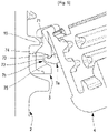
- the locking device is composed of a male fixing element 7a formed on the cap 4 and a female fixing element 7b formed on the ring 3.
- the male fixing element 7a of the cap 4 and the female fixing element 7b of the ring 3 cooperate with each other to keep the cap 4 with respect to ring 3 in the tilted open position illustrated in figures 3 and 4 .
- the male fixing element 7a comprises a main portion 71 protruding radially from the outer peripheral skirt 9, a first end of the main portion 71 being connected to the outer peripheral skirt 9, and also comprises a lug 72 connected to the main portion 71 at a second end of the main portion 71 opposite the first end.
- the lug 72 and the main portion 71 are inclined with respect to each other in a radial plane passing through the male fixing element 7a so that the male fixing element 7a is in the form of a hook.
- the male fixing element 7a is thus formed in line and centered above the articulation device 6.
- the male fixing element 7a is made to be formed on both sides of said joint plane in order to facilitate molding of the capping device 1.
- the female fixing element 7b comprises a housing 73 provided on the ring 3 and a heel 74 made on an outer surface of the ring 3.
- the heel 74 is designed to partially cover the housing 73 by projecting axially downward.
- an internal wall of the ring 3 the housing 73, then the heel 74 is located from the inside to the outside of the ring 3.
- the lug 72 is in front of the housing 73 at the level of the heel 74, then it is inserted after elastic deformation of the male fixing element 7a to the passage of the heel 74 in the housing 73.
- the lug 74 thus protrudes axially upwards when the cap 4 is in the tilted open position and is retained by the lug 74 thus forming a stop in the housing 73.
- the housing 73 comprises a beveled lower portion 75.
- the male fixing element 7a and the female fixing element 7b are made so that their greatest size is formed parallel to the axis of rotation of the capping device 1. In this way, the cooperation of the male fixing element 7a with the female fixing element 7b forms a long snap fit in this direction, more efficient for maintaining the tilted open position of the cap 4.
- the housing 73 is delimited downwards by a lower surface against which the lug 72 is intended to be supported during the movement of the cap 4 towards its tilted open position, which makes it possible to exert a downward force on the ring 3 and allows the second section 16 of the ring 3 to be brought back into the lowered position.
- the assembly of the capping device results from a single-piece molding of synthetic material, such as polyethylene and advantageously high-density polyethylene, for example.
- the capping device is molded in the configuration of figure 1 , that is, in a closed position, a position in which it can be mounted directly on the neck 2 of the container.
Landscapes
- Engineering & Computer Science (AREA)
- Mechanical Engineering (AREA)
- Closures For Containers (AREA)
Claims (14)
- Verschlussvorrichtung (1), die dazu bestimmt ist, auf einem Hals (2) eines Behälters befestigt zu werden, um eine Öffnung (5) des Halses (2) zu verschließen, wobei der Hals (2) einen Eingriffskragen (18) aufweist,wobei die Verschlussvorrichtung (1) umfasst:- eine Kappe (4) mit einer oberen Wand (8) und einer äußeren Umfangsschürze (9), wobei die Kappe (4) geeignet ist, in einer geschlossenen Position angeordnet zu werden, in der die obere Wand (8) die Öffnung (5) des Halses (2) verschließt und die Umfangsschürze (9) den Hals (2) umgibt;- einen Ring (3), der in der Verschlussposition unter der Kappe (4) angeordnet ist und einen ersten Abschnitt (15), der dazu bestimmt ist, axial im Eingriffskragen (18) des Halses (2) gehalten zu werden, und einen zweiten Abschnitt (16) umfasst, wobei der erste Abschnitt (15) und der zweite Abschnitt (16) des Rings (3) gelenkig miteinander verbunden sind, so dass der zweite Abschnitt (16) in Bezug auf den ersten Abschnitt (15) von einer abgesenkten Position in eine angehobene Position schwenkt, um es zu ermöglichen, dass sich die Kappe (4) axial vom Hals (2) weg von der geschlossenen Position in eine freigegebene Position bewegen kann, in der sich die Kappe (4) nicht mehr im Inneren des Halses (2) des Behälters befindet; und- eine Gelenkvorrichtung (6), die die Kappe (4) mit dem zweiten Abschnitt (16) des Rings (3) verbindet, wobei die Gelenkvorrichtung (6) so gestaltet ist, dass es möglich ist, dass die Kappe (4) entlang einer Drehachse zwischen der freigegebenen Position und einer gekippten offenen Position schwenken kann, in der der Stopfen (4) von der Öffnung (5) des Halses (2) freigegeben ist;wobei die Kappe (4) ein abstehendes Befestigungselement (7a) umfasst, das in der äußeren Umfangsschürze (9) ausgebildet ist und von der Kappe (4) radial nach außen vorsteht, und der zweite Abschnitt (16) des Rings (3) ein aufnehmendes Befestigungselement (7b) umfasst, wobei das abstehende Befestigungselement (7a) der Kappe (4) und das aufnehmende Befestigungselement (7b) des Rings (3) so gestaltet sind, dass sie miteinander zusammenwirken, um die Kappe (4) in Bezug auf den Ring (3) in der gekippten offenen Position zu halten,dadurch gekennzeichnet, dassdas abstehende Befestigungselement (7a) eine Lasche (72) umfasst, die axial nach oben vorsteht, wenn sich die Kappe (4) in der gekippten offenen Position befindet, und das aufnehmende Befestigungselement (7b) ein an dem Ring (3) vorgesehenes Gehäuse (73) und einen an einer Außenfläche des Rings (3) hergestellte Absatz (74) umfasst, der das Gehäuse (73) teilweise bedeckt und axial nach unten vorsteht, wobei die Lasche (72) so gestaltet ist, dass sie nach elastischer Verformung des abstehenden Befestigungselements (7a) beim Vorbeilaufen des Absatzes (74) in das Gehäuse (73) eingeführt und dort gehalten wird, sodass der Absatz (74) in der gekippten offenen Position einen Anschlag für die Lasche (72) bildet, undund dass das Gehäuse (73) nach unten durch eine untere Fläche (75) begrenzt ist, wobei die Lasche (72) so ausgestaltet ist, dass sie während der Bewegung der Kappe (4) in Richtung der gekippten offenen Position gegen diese anliegt, um auf den Ring (3) eine nach unten gerichtete Kraft auszuüben, die es ermöglicht, den zweiten Abschnitt (16) des Rings (3) in die abgesenkte Position zurückzubringen.
- Verschlussvorrichtung (1) nach Anspruch 1, wobei die Lasche (72) und der Absatz (74) sich parallel zur Drehachse erstrecken.
- Verschlussvorrichtung (1) nach Anspruch 1 oder Anspruch 2, wobei das abstehende Befestigungselement (7a) einen Hauptabschnitt (71) umfasst, der die Lasche (72) mit der äußeren Umfangsschürze (9) der Kappe (4) verbindet, wobei die Lasche (72) und der Hauptabschnitt (71) relativ zueinander geneigt sind, um einen Haken zu bilden.
- Verschlussvorrichtung (1) nach einem der Ansprüche 1 bis 3, wobei die Verschlussvorrichtung (1) durch Formen mit Hilfe von zwei Halbschalen hergestellt ist, die auf der Höhe einer radialen Verbindungsebene zusammengefügt sind, wobei das abstehende Befestigungselement (7a) des Stopfens (4) und das aufnehmende Befestigungselement (7b) des Rings (3) jeweils auf beiden Seiten der gemeinsamen Ebene angebracht sind.
- Verschlussvorrichtung (1) nach Anspruch 4, wobei die gemeinsame Ebene so ausgerichtet ist, dass sie durch eine zentrale Achse X der Verschlussvorrichtung (1) und durch die Mitte der Gelenkvorrichtung (6) verläuft.
- Verschlussvorrichtung (1) nach einem der Ansprüche 1 bis 5, wobei das abstehende Befestigungselement (7a) der Kappe (4) in einer Linie und zentriert über der Gelenkvorrichtung (6) ausgebildet ist.
- Verschlussvorrichtung (1) nach einem der Ansprüche 1 bis 6, wobei das aufnehmende Befestigungselement (7b) des Rings (3) in einer Linie und zentriert unterhalb der Gelenkvorrichtung (6) ausgebildet ist.
- Verschlussvorrichtung nach einem der Ansprüche 1 bis 7, wobei die Gelenkvorrichtung (6) eine verformbare Platte (21) umfasst, die die äußere Umfangsschürze (9) und den zweiten Abschnitt (16) des Rings (3) verbindet.
- Verschlussvorrichtung (1) nach Anspruch 8, wobei die verformbare Platte (21) einen vorbestimmten Schwenkbereich (22) umfasst, der so gestaltet ist, dass sich die Drehachse der Verschlussvorrichtung (1) in diesem vorbestimmten Schwenkbereich (22) befindet.
- Verschlussvorrichtung (1) nach Anspruch 9, wobei der vorbestimmte Schwenkbereich (22) mit Hilfe eines Zickzack-Abschnitts (23) der verformbaren Platte (21) hergestellt ist.
- Verschlussvorrichtung (1) nach einem der Ansprüche 1 bis 10, wobei der Ring (3) dazu bestimmt ist, drehbar auf dem Hals (2) um eine zentrale Achse X der Verschussvorrichtung (1) angebracht zu werden, und wobei die äußere Umfangsschürze (9) der Kappe (4) ein schraubenförmiges Gewinde (10) aufweist, das dazu bestimmt ist, mit einem schraubenförmigen Gewinde (11) zusammenzuwirken, das am Hals (2) des Behälters vorgesehen ist, um das Auf- oder Abschrauben der Kappe (4) im Hals (2) um die zentrale Achse X zu ermöglichen.
- Verschlussvorrichtung (1) nach einem der Ansprüche 1 bis 10, wobei der Ring (3) eine Kerbe aufweist, die so gestaltet ist, dass sie den Ring (3) lokal vom Eingriffskragen (18) ablenkt, wobei die Kerbe diametral gegenüber der Gelenkvorrichtung (6) liegt, und die Kappe (4) ein Schließelement aufweist, das axial von der äußeren Umfangsschürze (9) vorsteht und der Gelenkvorrichtung (6) diametral gegenüberliegt, wobei das Schließelement dazu bestimmt ist, mit dem am Hals (2) vorgesehenen Eingriffskragen (18) zusammenzuwirken, um das Schließelement in der Kerbe zu positionieren und die Kappe (4) in der geschlossenen Position zu halten.
- Verschlussvorrichtung (1) nach einem der Ansprüche 1 bis 12, wobei der untere Ring (3) durch zerbrechliche Brücken (14) mit der äußeren Umfangsschürze (9) verbunden ist.
- Anordnung, die einen Behälter umfasst, der mit einem Hals (2) ausgestattet ist, der einen Eingriffskragen (18) und eine Öffnung (5) umfasst, und der mit einer Verschlussvorrichtung (1) nach einem der Ansprüche 1 bis 13 ausgestattet ist, wobei der erste Abschnitt (15) des Rings (3) der Verschlussvorrichtung (1) axial in dem Eingriffskragen (18) des Halses (2) gehalten ist.
Applications Claiming Priority (1)
| Application Number | Priority Date | Filing Date | Title |
|---|---|---|---|
| ES201931148A ES2836024B2 (es) | 2019-12-23 | 2019-12-23 | Dispositivo de taponado destinado a ser fijado en un cuello de un recipiente |
Publications (2)
| Publication Number | Publication Date |
|---|---|
| EP3842358A1 EP3842358A1 (de) | 2021-06-30 |
| EP3842358B1 true EP3842358B1 (de) | 2022-08-03 |
Family
ID=74105796
Family Applications (1)
| Application Number | Title | Priority Date | Filing Date |
|---|---|---|---|
| EP20383111.0A Active EP3842358B1 (de) | 2019-12-23 | 2020-12-17 | Abdeckvorrichtung zur befestigung an einem hals eines behälters |
Country Status (6)
| Country | Link |
|---|---|
| EP (1) | EP3842358B1 (de) |
| DK (1) | DK3842358T3 (de) |
| ES (2) | ES2836024B2 (de) |
| MA (1) | MA54408A (de) |
| PL (1) | PL3842358T3 (de) |
| PT (1) | PT3842358T (de) |
Families Citing this family (6)
| Publication number | Priority date | Publication date | Assignee | Title |
|---|---|---|---|---|
| ES1281455Y (es) | 2021-07-29 | 2022-02-01 | Sanchez Jose Francisco Gonzalez | Tapón de cierre para envases |
| ES1279073U (es) * | 2021-08-27 | 2021-10-13 | Sanchez Jose Francisco Gonzalez | Tapón de cierre enroscable para envases y un envase provisto de dicho tapón |
| CN119013196A (zh) * | 2022-04-26 | 2024-11-22 | 百利盖控股有限公司 | 带有稳定化连接元件的系留式封闭装置 |
| SE547849C2 (en) * | 2022-12-20 | 2025-12-09 | Emballator Vaexjoe Ab | A cap with a threaded portion for securing said cap to a bottle, the bottle and a method for manufacturing such a cap |
| IT202300001302A1 (it) * | 2023-01-27 | 2024-07-27 | Sacmi | Assieme di chiusura di un contenitore. |
| GR1010549B (el) * | 2023-02-03 | 2023-09-25 | Σωτηριος Δημητριου Κουρτης | Καπακι μη - αποσπωμενου τυπου |
Family Cites Families (8)
| Publication number | Priority date | Publication date | Assignee | Title |
|---|---|---|---|---|
| US4158902A (en) * | 1977-09-30 | 1979-06-26 | Chernack Milton P | Integral snap action hinge |
| KR200182811Y1 (ko) * | 1999-12-11 | 2000-05-15 | 이붕주 | 음료용기 캡 구조 |
| KR100880006B1 (ko) * | 2007-12-07 | 2009-01-22 | (주)베스트이지캡 | 마개가 버팀지지되는 용기 |
| MX2010003933A (es) * | 2007-10-10 | 2010-11-26 | Best Easy Cap Co Ltd | Recipiente con tapa anti-perdida y anti-rotacion indebida. |
| RU2478542C2 (ru) * | 2008-07-08 | 2013-04-10 | Джапан Краун Корк Ко., Лтд. | Выполненная из синтетической смолы крышка контейнера |
| CN109311567A (zh) | 2016-03-04 | 2019-02-05 | 贝塔派克有限公司 | 用于容器的帽 |
| ES2712094B2 (es) * | 2018-06-12 | 2019-10-17 | Sanchez Jose Francisco Gonzalez | Tapón abatible para envases |
| ES1232089Y (es) * | 2019-05-28 | 2019-09-27 | Sanchez Jose Francisco Gonzalez | Tapón de cierre para envases |
-
2019
- 2019-12-23 ES ES201931148A patent/ES2836024B2/es not_active Expired - Fee Related
-
2020
- 2020-12-17 DK DK20383111.0T patent/DK3842358T3/da active
- 2020-12-17 ES ES20383111T patent/ES2929600T3/es active Active
- 2020-12-17 PL PL20383111.0T patent/PL3842358T3/pl unknown
- 2020-12-17 MA MA054408A patent/MA54408A/fr unknown
- 2020-12-17 PT PT203831110T patent/PT3842358T/pt unknown
- 2020-12-17 EP EP20383111.0A patent/EP3842358B1/de active Active
Also Published As
| Publication number | Publication date |
|---|---|
| ES2836024A1 (es) | 2021-06-23 |
| PT3842358T (pt) | 2022-11-09 |
| ES2836024B2 (es) | 2021-10-28 |
| ES2929600T3 (es) | 2022-11-30 |
| MA54408A (fr) | 2022-05-11 |
| DK3842358T3 (en) | 2022-11-07 |
| PL3842358T3 (pl) | 2022-12-12 |
| EP3842358A1 (de) | 2021-06-30 |
Similar Documents
| Publication | Publication Date | Title |
|---|---|---|
| EP3842358A1 (de) | Abdeckvorrichtung zur befestigung an einem hals eines behälters | |
| EP3950528B1 (de) | Verschlussvorrichtung zur befestigung an einem hals eines behälters | |
| US11718450B2 (en) | Capping device intended to be fixed on the neck of a container and an assembly comprising a container and a capping device | |
| US4709823A (en) | Tamper evident bottle or package closure | |
| US6874664B1 (en) | Push-pull dispenser with folding fingers | |
| US6041982A (en) | Beverage container with cap and spout | |
| CA2294657C (en) | Tamper-evident closure with abutment | |
| US6062441A (en) | Two-piece dispensing closure | |
| US6234334B1 (en) | Single-piece plastic lid | |
| JPH0516961A (ja) | 開口カプセルとタンパプルーフ用カバー付き容器とを含む組立て体 | |
| CN113924257A (zh) | 用于容器的封闭盖及其制造方法 | |
| US3967745A (en) | Self-positioning child-resistant closure | |
| EP4095064B1 (de) | Eine verschliessvorrichtung, die dazu bestimmt ist, auf dem hals eines behälters befestigt zu werden, und eine baugruppe, die einen behälter und die verschliessvorrichtung umfasst | |
| CN113646236A (zh) | 合成树脂制容器盖 | |
| US7635071B1 (en) | Double shell dispensing closure with a reverse tapered drop lug | |
| EP4095063B1 (de) | Verschliessvorrichtung für den hals eines behälters | |
| EP4095062B1 (de) | Verschliessvorrichtung für den hals eines behälters | |
| US20090120899A1 (en) | Flip top container closure | |
| US4717033A (en) | Plastic closure with safety band | |
| US5931357A (en) | Closure arrangements for containers | |
| US20240002116A1 (en) | Assembly Comprising A Container And Plugging Device Attached To The Container | |
| HK40060830B (en) | Capping device intended to be fixed on the neck of a container | |
| JP7791044B2 (ja) | キャップ体 | |
| RU2809536C1 (ru) | Укупорочное средство контейнера, образованное из синтетической смолы | |
| HK40060830A (en) | Capping device intended to be fixed on the neck of a container |
Legal Events
| Date | Code | Title | Description |
|---|---|---|---|
| PUAI | Public reference made under article 153(3) epc to a published international application that has entered the european phase |
Free format text: ORIGINAL CODE: 0009012 |
|
| STAA | Information on the status of an ep patent application or granted ep patent |
Free format text: STATUS: THE APPLICATION HAS BEEN PUBLISHED |
|
| AK | Designated contracting states |
Kind code of ref document: A1 Designated state(s): AL AT BE BG CH CY CZ DE DK EE ES FI FR GB GR HR HU IE IS IT LI LT LU LV MC MK MT NL NO PL PT RO RS SE SI SK SM TR |
|
| STAA | Information on the status of an ep patent application or granted ep patent |
Free format text: STATUS: REQUEST FOR EXAMINATION WAS MADE |
|
| 17P | Request for examination filed |
Effective date: 20210908 |
|
| RAV | Requested validation state of the european patent: fee paid |
Extension state: TN Effective date: 20210908 Extension state: MA Effective date: 20210908 |
|
| RBV | Designated contracting states (corrected) |
Designated state(s): AL AT BE BG CH CY CZ DE DK EE ES FI FR GB GR HR HU IE IS IT LI LT LU LV MC MK MT NL NO PL PT RO RS SE SI SK SM TR |
|
| GRAP | Despatch of communication of intention to grant a patent |
Free format text: ORIGINAL CODE: EPIDOSNIGR1 |
|
| STAA | Information on the status of an ep patent application or granted ep patent |
Free format text: STATUS: GRANT OF PATENT IS INTENDED |
|
| INTG | Intention to grant announced |
Effective date: 20220414 |
|
| GRAS | Grant fee paid |
Free format text: ORIGINAL CODE: EPIDOSNIGR3 |
|
| GRAA | (expected) grant |
Free format text: ORIGINAL CODE: 0009210 |
|
| STAA | Information on the status of an ep patent application or granted ep patent |
Free format text: STATUS: THE PATENT HAS BEEN GRANTED |
|
| AK | Designated contracting states |
Kind code of ref document: B1 Designated state(s): AL AT BE BG CH CY CZ DE DK EE ES FI FR GB GR HR HU IE IS IT LI LT LU LV MC MK MT NL NO PL PT RO RS SE SI SK SM TR |
|
| REG | Reference to a national code |
Ref country code: AT Ref legal event code: REF Ref document number: 1508576 Country of ref document: AT Kind code of ref document: T Effective date: 20220815 Ref country code: CH Ref legal event code: EP |
|
| REG | Reference to a national code |
Ref country code: DE Ref legal event code: R096 Ref document number: 602020004347 Country of ref document: DE |
|
| REG | Reference to a national code |
Ref country code: IE Ref legal event code: FG4D |
|
| REG | Reference to a national code |
Ref country code: DK Ref legal event code: T3 Effective date: 20221101 |
|
| REG | Reference to a national code |
Ref country code: PT Ref legal event code: SC4A Ref document number: 3842358 Country of ref document: PT Date of ref document: 20221109 Kind code of ref document: T Free format text: AVAILABILITY OF NATIONAL TRANSLATION Effective date: 20221103 |
|
| REG | Reference to a national code |
Ref country code: NL Ref legal event code: FP |
|
| REG | Reference to a national code |
Ref country code: LT Ref legal event code: MG9D |
|
| REG | Reference to a national code |
Ref country code: ES Ref legal event code: FG2A Ref document number: 2929600 Country of ref document: ES Kind code of ref document: T3 Effective date: 20221130 |
|
| PG25 | Lapsed in a contracting state [announced via postgrant information from national office to epo] |
Ref country code: SE Free format text: LAPSE BECAUSE OF FAILURE TO SUBMIT A TRANSLATION OF THE DESCRIPTION OR TO PAY THE FEE WITHIN THE PRESCRIBED TIME-LIMIT Effective date: 20220803 Ref country code: RS Free format text: LAPSE BECAUSE OF FAILURE TO SUBMIT A TRANSLATION OF THE DESCRIPTION OR TO PAY THE FEE WITHIN THE PRESCRIBED TIME-LIMIT Effective date: 20220803 Ref country code: NO Free format text: LAPSE BECAUSE OF FAILURE TO SUBMIT A TRANSLATION OF THE DESCRIPTION OR TO PAY THE FEE WITHIN THE PRESCRIBED TIME-LIMIT Effective date: 20221103 Ref country code: LV Free format text: LAPSE BECAUSE OF FAILURE TO SUBMIT A TRANSLATION OF THE DESCRIPTION OR TO PAY THE FEE WITHIN THE PRESCRIBED TIME-LIMIT Effective date: 20220803 Ref country code: LT Free format text: LAPSE BECAUSE OF FAILURE TO SUBMIT A TRANSLATION OF THE DESCRIPTION OR TO PAY THE FEE WITHIN THE PRESCRIBED TIME-LIMIT Effective date: 20220803 Ref country code: FI Free format text: LAPSE BECAUSE OF FAILURE TO SUBMIT A TRANSLATION OF THE DESCRIPTION OR TO PAY THE FEE WITHIN THE PRESCRIBED TIME-LIMIT Effective date: 20220803 |
|
| PG25 | Lapsed in a contracting state [announced via postgrant information from national office to epo] |
Ref country code: IS Free format text: LAPSE BECAUSE OF FAILURE TO SUBMIT A TRANSLATION OF THE DESCRIPTION OR TO PAY THE FEE WITHIN THE PRESCRIBED TIME-LIMIT Effective date: 20221203 Ref country code: HR Free format text: LAPSE BECAUSE OF FAILURE TO SUBMIT A TRANSLATION OF THE DESCRIPTION OR TO PAY THE FEE WITHIN THE PRESCRIBED TIME-LIMIT Effective date: 20220803 Ref country code: GR Free format text: LAPSE BECAUSE OF FAILURE TO SUBMIT A TRANSLATION OF THE DESCRIPTION OR TO PAY THE FEE WITHIN THE PRESCRIBED TIME-LIMIT Effective date: 20221104 |
|
| PG25 | Lapsed in a contracting state [announced via postgrant information from national office to epo] |
Ref country code: SM Free format text: LAPSE BECAUSE OF FAILURE TO SUBMIT A TRANSLATION OF THE DESCRIPTION OR TO PAY THE FEE WITHIN THE PRESCRIBED TIME-LIMIT Effective date: 20220803 Ref country code: RO Free format text: LAPSE BECAUSE OF FAILURE TO SUBMIT A TRANSLATION OF THE DESCRIPTION OR TO PAY THE FEE WITHIN THE PRESCRIBED TIME-LIMIT Effective date: 20220803 |
|
| REG | Reference to a national code |
Ref country code: DE Ref legal event code: R097 Ref document number: 602020004347 Country of ref document: DE |
|
| PG25 | Lapsed in a contracting state [announced via postgrant information from national office to epo] |
Ref country code: SK Free format text: LAPSE BECAUSE OF FAILURE TO SUBMIT A TRANSLATION OF THE DESCRIPTION OR TO PAY THE FEE WITHIN THE PRESCRIBED TIME-LIMIT Effective date: 20220803 Ref country code: EE Free format text: LAPSE BECAUSE OF FAILURE TO SUBMIT A TRANSLATION OF THE DESCRIPTION OR TO PAY THE FEE WITHIN THE PRESCRIBED TIME-LIMIT Effective date: 20220803 |
|
| PLBE | No opposition filed within time limit |
Free format text: ORIGINAL CODE: 0009261 |
|
| STAA | Information on the status of an ep patent application or granted ep patent |
Free format text: STATUS: NO OPPOSITION FILED WITHIN TIME LIMIT |
|
| PG25 | Lapsed in a contracting state [announced via postgrant information from national office to epo] |
Ref country code: AL Free format text: LAPSE BECAUSE OF FAILURE TO SUBMIT A TRANSLATION OF THE DESCRIPTION OR TO PAY THE FEE WITHIN THE PRESCRIBED TIME-LIMIT Effective date: 20220803 |
|
| 26N | No opposition filed |
Effective date: 20230504 |
|
| P01 | Opt-out of the competence of the unified patent court (upc) registered |
Effective date: 20230602 |
|
| REG | Reference to a national code |
Ref country code: AT Ref legal event code: UEP Ref document number: 1508576 Country of ref document: AT Kind code of ref document: T Effective date: 20220803 |
|
| PG25 | Lapsed in a contracting state [announced via postgrant information from national office to epo] |
Ref country code: SI Free format text: LAPSE BECAUSE OF FAILURE TO SUBMIT A TRANSLATION OF THE DESCRIPTION OR TO PAY THE FEE WITHIN THE PRESCRIBED TIME-LIMIT Effective date: 20220803 Ref country code: LU Free format text: LAPSE BECAUSE OF NON-PAYMENT OF DUE FEES Effective date: 20221217 |
|
| PGFP | Annual fee paid to national office [announced via postgrant information from national office to epo] |
Ref country code: NL Payment date: 20231116 Year of fee payment: 4 |
|
| PGFP | Annual fee paid to national office [announced via postgrant information from national office to epo] |
Ref country code: PT Payment date: 20231204 Year of fee payment: 4 Ref country code: IE Payment date: 20231115 Year of fee payment: 4 Ref country code: FR Payment date: 20231212 Year of fee payment: 4 Ref country code: DK Payment date: 20231106 Year of fee payment: 4 Ref country code: DE Payment date: 20231214 Year of fee payment: 4 Ref country code: CZ Payment date: 20231211 Year of fee payment: 4 |
|
| PGFP | Annual fee paid to national office [announced via postgrant information from national office to epo] |
Ref country code: PL Payment date: 20231109 Year of fee payment: 4 Ref country code: BE Payment date: 20231103 Year of fee payment: 4 |
|
| PGFP | Annual fee paid to national office [announced via postgrant information from national office to epo] |
Ref country code: ES Payment date: 20240105 Year of fee payment: 4 |
|
| PG25 | Lapsed in a contracting state [announced via postgrant information from national office to epo] |
Ref country code: CY Free format text: LAPSE BECAUSE OF FAILURE TO SUBMIT A TRANSLATION OF THE DESCRIPTION OR TO PAY THE FEE WITHIN THE PRESCRIBED TIME-LIMIT Effective date: 20220803 |
|
| PGFP | Annual fee paid to national office [announced via postgrant information from national office to epo] |
Ref country code: CH Payment date: 20240101 Year of fee payment: 4 |
|
| PG25 | Lapsed in a contracting state [announced via postgrant information from national office to epo] |
Ref country code: MK Free format text: LAPSE BECAUSE OF FAILURE TO SUBMIT A TRANSLATION OF THE DESCRIPTION OR TO PAY THE FEE WITHIN THE PRESCRIBED TIME-LIMIT Effective date: 20220803 |
|
| PGFP | Annual fee paid to national office [announced via postgrant information from national office to epo] |
Ref country code: TR Payment date: 20231215 Year of fee payment: 4 Ref country code: IT Payment date: 20240102 Year of fee payment: 4 |
|
| PG25 | Lapsed in a contracting state [announced via postgrant information from national office to epo] |
Ref country code: MC Free format text: LAPSE BECAUSE OF FAILURE TO SUBMIT A TRANSLATION OF THE DESCRIPTION OR TO PAY THE FEE WITHIN THE PRESCRIBED TIME-LIMIT Effective date: 20220803 |
|
| PG25 | Lapsed in a contracting state [announced via postgrant information from national office to epo] |
Ref country code: MC Free format text: LAPSE BECAUSE OF FAILURE TO SUBMIT A TRANSLATION OF THE DESCRIPTION OR TO PAY THE FEE WITHIN THE PRESCRIBED TIME-LIMIT Effective date: 20220803 |
|
| PG25 | Lapsed in a contracting state [announced via postgrant information from national office to epo] |
Ref country code: BG Free format text: LAPSE BECAUSE OF FAILURE TO SUBMIT A TRANSLATION OF THE DESCRIPTION OR TO PAY THE FEE WITHIN THE PRESCRIBED TIME-LIMIT Effective date: 20220803 |
|
| PG25 | Lapsed in a contracting state [announced via postgrant information from national office to epo] |
Ref country code: MT Free format text: LAPSE BECAUSE OF FAILURE TO SUBMIT A TRANSLATION OF THE DESCRIPTION OR TO PAY THE FEE WITHIN THE PRESCRIBED TIME-LIMIT Effective date: 20220803 |
|
| REG | Reference to a national code |
Ref country code: DE Ref legal event code: R119 Ref document number: 602020004347 Country of ref document: DE |
|
| PG25 | Lapsed in a contracting state [announced via postgrant information from national office to epo] |
Ref country code: PT Free format text: LAPSE BECAUSE OF NON-PAYMENT OF DUE FEES Effective date: 20250617 |
|
| REG | Reference to a national code |
Ref country code: DK Ref legal event code: EBP Effective date: 20241231 |
|
| PG25 | Lapsed in a contracting state [announced via postgrant information from national office to epo] |
Ref country code: CZ Free format text: LAPSE BECAUSE OF NON-PAYMENT OF DUE FEES Effective date: 20241217 |
|
| REG | Reference to a national code |
Ref country code: CH Ref legal event code: PL |
|
| PG25 | Lapsed in a contracting state [announced via postgrant information from national office to epo] |
Ref country code: HU Free format text: LAPSE BECAUSE OF FAILURE TO SUBMIT A TRANSLATION OF THE DESCRIPTION OR TO PAY THE FEE WITHIN THE PRESCRIBED TIME-LIMIT; INVALID AB INITIO Effective date: 20201217 |
|
| REG | Reference to a national code |
Ref country code: NL Ref legal event code: MM Effective date: 20250101 |
|
| GBPC | Gb: european patent ceased through non-payment of renewal fee |
Effective date: 20241217 |
|
| PG25 | Lapsed in a contracting state [announced via postgrant information from national office to epo] |
Ref country code: NL Free format text: LAPSE BECAUSE OF NON-PAYMENT OF DUE FEES Effective date: 20250101 |
|
| REG | Reference to a national code |
Ref country code: BE Ref legal event code: MM Effective date: 20241231 |
|
| PG25 | Lapsed in a contracting state [announced via postgrant information from national office to epo] |
Ref country code: DE Free format text: LAPSE BECAUSE OF NON-PAYMENT OF DUE FEES Effective date: 20250701 |
|
| PG25 | Lapsed in a contracting state [announced via postgrant information from national office to epo] |
Ref country code: IT Free format text: LAPSE BECAUSE OF NON-PAYMENT OF DUE FEES Effective date: 20241217 |
|
| PG25 | Lapsed in a contracting state [announced via postgrant information from national office to epo] |
Ref country code: GB Free format text: LAPSE BECAUSE OF NON-PAYMENT OF DUE FEES Effective date: 20241217 Ref country code: BE Free format text: LAPSE BECAUSE OF NON-PAYMENT OF DUE FEES Effective date: 20241231 |
|
| PG25 | Lapsed in a contracting state [announced via postgrant information from national office to epo] |
Ref country code: FR Free format text: LAPSE BECAUSE OF NON-PAYMENT OF DUE FEES Effective date: 20241231 |
|
| PG25 | Lapsed in a contracting state [announced via postgrant information from national office to epo] |
Ref country code: CH Free format text: LAPSE BECAUSE OF NON-PAYMENT OF DUE FEES Effective date: 20241231 |
|
| PG25 | Lapsed in a contracting state [announced via postgrant information from national office to epo] |
Ref country code: IE Free format text: LAPSE BECAUSE OF NON-PAYMENT OF DUE FEES Effective date: 20241217 |
|
| VS25 | Lapsed in a validation state [announced via postgrant information from nat. office to epo] |
Ref country code: MA Free format text: FAILURE TO ELECT DOMICILE IN THE NATIONAL COUNTRY Effective date: 20221104 |
|
| PG25 | Lapsed in a contracting state [announced via postgrant information from national office to epo] |
Ref country code: DK Free format text: LAPSE BECAUSE OF NON-PAYMENT OF DUE FEES Effective date: 20241231 |
|
| PGFP | Annual fee paid to national office [announced via postgrant information from national office to epo] |
Ref country code: AT Payment date: 20260113 Year of fee payment: 5 |
|
| REG | Reference to a national code |
Ref country code: ES Ref legal event code: FD2A Effective date: 20260127 |
|
| PG25 | Lapsed in a contracting state [announced via postgrant information from national office to epo] |
Ref country code: ES Free format text: LAPSE BECAUSE OF NON-PAYMENT OF DUE FEES Effective date: 20241218 |
|
| PG25 | Lapsed in a contracting state [announced via postgrant information from national office to epo] |
Ref country code: TR Free format text: LAPSE BECAUSE OF NON-PAYMENT OF DUE FEES Effective date: 20241217 |
|
| PG25 | Lapsed in a contracting state [announced via postgrant information from national office to epo] |
Ref country code: PL Free format text: LAPSE BECAUSE OF NON-PAYMENT OF DUE FEES Effective date: 20241217 |