EP3842360A1 - Support pour récipients - Google Patents
Support pour récipients Download PDFInfo
- Publication number
- EP3842360A1 EP3842360A1 EP20168268.9A EP20168268A EP3842360A1 EP 3842360 A1 EP3842360 A1 EP 3842360A1 EP 20168268 A EP20168268 A EP 20168268A EP 3842360 A1 EP3842360 A1 EP 3842360A1
- Authority
- EP
- European Patent Office
- Prior art keywords
- panel
- blank
- handle
- construct
- carrier
- Prior art date
- Legal status (The legal status is an assumption and is not a legal conclusion. Google has not performed a legal analysis and makes no representation as to the accuracy of the status listed.)
- Withdrawn
Links
- 239000003292 glue Substances 0.000 claims description 79
- 230000014759 maintenance of location Effects 0.000 claims description 65
- 239000000463 material Substances 0.000 claims description 23
- 238000000034 method Methods 0.000 claims description 14
- 230000002787 reinforcement Effects 0.000 claims description 10
- 239000000853 adhesive Substances 0.000 description 13
- 230000001070 adhesive effect Effects 0.000 description 13
- 235000013361 beverage Nutrition 0.000 description 6
- 239000000969 carrier Substances 0.000 description 6
- 238000000926 separation method Methods 0.000 description 5
- 239000007787 solid Substances 0.000 description 4
- 230000008901 benefit Effects 0.000 description 3
- 239000013256 coordination polymer Substances 0.000 description 3
- 238000012986 modification Methods 0.000 description 3
- 230000004048 modification Effects 0.000 description 3
- 239000005020 polyethylene terephthalate Substances 0.000 description 3
- 229920000139 polyethylene terephthalate Polymers 0.000 description 3
- 230000003014 reinforcing effect Effects 0.000 description 3
- 230000015572 biosynthetic process Effects 0.000 description 2
- 239000004927 clay Substances 0.000 description 2
- 239000011248 coating agent Substances 0.000 description 2
- 238000000576 coating method Methods 0.000 description 2
- 238000005520 cutting process Methods 0.000 description 2
- 239000012530 fluid Substances 0.000 description 2
- 239000006260 foam Substances 0.000 description 2
- 238000002372 labelling Methods 0.000 description 2
- 239000007788 liquid Substances 0.000 description 2
- 238000004806 packaging method and process Methods 0.000 description 2
- 239000011087 paperboard Substances 0.000 description 2
- 239000004033 plastic Substances 0.000 description 2
- 229920003023 plastic Polymers 0.000 description 2
- -1 polyethylene terephthalate Polymers 0.000 description 2
- 230000001737 promoting effect Effects 0.000 description 2
- 238000003860 storage Methods 0.000 description 2
- 230000003313 weakening effect Effects 0.000 description 2
- VGGSQFUCUMXWEO-UHFFFAOYSA-N Ethene Chemical compound C=C VGGSQFUCUMXWEO-UHFFFAOYSA-N 0.000 description 1
- 229920000219 Ethylene vinyl alcohol Polymers 0.000 description 1
- 239000004677 Nylon Substances 0.000 description 1
- 239000004743 Polypropylene Substances 0.000 description 1
- 239000004793 Polystyrene Substances 0.000 description 1
- 238000007792 addition Methods 0.000 description 1
- 229910052782 aluminium Inorganic materials 0.000 description 1
- XAGFODPZIPBFFR-UHFFFAOYSA-N aluminium Chemical compound [Al] XAGFODPZIPBFFR-UHFFFAOYSA-N 0.000 description 1
- 230000004888 barrier function Effects 0.000 description 1
- 239000011111 cardboard Substances 0.000 description 1
- 230000008859 change Effects 0.000 description 1
- 230000000994 depressogenic effect Effects 0.000 description 1
- UFRKOOWSQGXVKV-UHFFFAOYSA-N ethene;ethenol Chemical compound C=C.OC=C UFRKOOWSQGXVKV-UHFFFAOYSA-N 0.000 description 1
- 239000004715 ethylene vinyl alcohol Substances 0.000 description 1
- 239000000835 fiber Substances 0.000 description 1
- 239000011521 glass Substances 0.000 description 1
- 229920001903 high density polyethylene Polymers 0.000 description 1
- 239000004700 high-density polyethylene Substances 0.000 description 1
- 238000010348 incorporation Methods 0.000 description 1
- 229920000092 linear low density polyethylene Polymers 0.000 description 1
- 239000004707 linear low-density polyethylene Substances 0.000 description 1
- 229920001684 low density polyethylene Polymers 0.000 description 1
- 239000004702 low-density polyethylene Substances 0.000 description 1
- 229910052751 metal Inorganic materials 0.000 description 1
- 239000002184 metal Substances 0.000 description 1
- 150000002739 metals Chemical class 0.000 description 1
- 239000000203 mixture Substances 0.000 description 1
- 229920001778 nylon Polymers 0.000 description 1
- 239000000123 paper Substances 0.000 description 1
- 229920000915 polyvinyl chloride Polymers 0.000 description 1
- 239000004800 polyvinyl chloride Substances 0.000 description 1
- 238000003825 pressing Methods 0.000 description 1
- 230000009467 reduction Effects 0.000 description 1
- 238000005728 strengthening Methods 0.000 description 1
- 239000002966 varnish Substances 0.000 description 1
- 239000002699 waste material Substances 0.000 description 1
Images




Classifications
-
- B—PERFORMING OPERATIONS; TRANSPORTING
- B65—CONVEYING; PACKING; STORING; HANDLING THIN OR FILAMENTARY MATERIAL
- B65D—CONTAINERS FOR STORAGE OR TRANSPORT OF ARTICLES OR MATERIALS, e.g. BAGS, BARRELS, BOTTLES, BOXES, CANS, CARTONS, CRATES, DRUMS, JARS, TANKS, HOPPERS, FORWARDING CONTAINERS; ACCESSORIES, CLOSURES, OR FITTINGS THEREFOR; PACKAGING ELEMENTS; PACKAGES
- B65D71/00—Bundles of articles held together by packaging elements for convenience of storage or transport, e.g. portable segregating carrier for plural receptacles such as beer cans or pop bottles; Bales of material
- B65D71/40—Bundles of articles held together by packaging elements for convenience of storage or transport, e.g. portable segregating carrier for plural receptacles such as beer cans or pop bottles; Bales of material comprising a plurality of articles held together only partially by packaging elements formed by folding a blank or several blanks
- B65D71/403—Bundles of articles held together by packaging elements for convenience of storage or transport, e.g. portable segregating carrier for plural receptacles such as beer cans or pop bottles; Bales of material comprising a plurality of articles held together only partially by packaging elements formed by folding a blank or several blanks formed by folding several blanks
- B65D71/406—Bundles of articles held together by packaging elements for convenience of storage or transport, e.g. portable segregating carrier for plural receptacles such as beer cans or pop bottles; Bales of material comprising a plurality of articles held together only partially by packaging elements formed by folding a blank or several blanks formed by folding several blanks characterised by the handle
-
- B—PERFORMING OPERATIONS; TRANSPORTING
- B65—CONVEYING; PACKING; STORING; HANDLING THIN OR FILAMENTARY MATERIAL
- B65D—CONTAINERS FOR STORAGE OR TRANSPORT OF ARTICLES OR MATERIALS, e.g. BAGS, BARRELS, BOTTLES, BOXES, CANS, CARTONS, CRATES, DRUMS, JARS, TANKS, HOPPERS, FORWARDING CONTAINERS; ACCESSORIES, CLOSURES, OR FITTINGS THEREFOR; PACKAGING ELEMENTS; PACKAGES
- B65D71/00—Bundles of articles held together by packaging elements for convenience of storage or transport, e.g. portable segregating carrier for plural receptacles such as beer cans or pop bottles; Bales of material
- B65D71/40—Bundles of articles held together by packaging elements for convenience of storage or transport, e.g. portable segregating carrier for plural receptacles such as beer cans or pop bottles; Bales of material comprising a plurality of articles held together only partially by packaging elements formed by folding a blank or several blanks
- B65D71/42—Bundles of articles held together by packaging elements for convenience of storage or transport, e.g. portable segregating carrier for plural receptacles such as beer cans or pop bottles; Bales of material comprising a plurality of articles held together only partially by packaging elements formed by folding a blank or several blanks formed by folding a single blank into a single layer element
- B65D71/44—Bundles of articles held together by packaging elements for convenience of storage or transport, e.g. portable segregating carrier for plural receptacles such as beer cans or pop bottles; Bales of material comprising a plurality of articles held together only partially by packaging elements formed by folding a blank or several blanks formed by folding a single blank into a single layer element characterised by the handle
-
- B—PERFORMING OPERATIONS; TRANSPORTING
- B65—CONVEYING; PACKING; STORING; HANDLING THIN OR FILAMENTARY MATERIAL
- B65B—MACHINES, APPARATUS OR DEVICES FOR, OR METHODS OF, PACKAGING ARTICLES OR MATERIALS; UNPACKING
- B65B17/00—Other machines, apparatus, or methods for packaging articles or materials
- B65B17/02—Joining articles, e.g. cans, directly to each other for convenience of storage, transport, or handling
- B65B17/025—Joining articles, e.g. cans, directly to each other for convenience of storage, transport, or handling the articles being joined by a top carrier element
Definitions
- the present disclosure generally relates to cartons or carriers for holding, displaying, and/or transporting containers.
- a carrier for holding a plurality of containers comprises a first construct and a second construct.
- the first construct comprises a plurality of panels including at least one central panel and at least one attachment panel configured to receive a portion of one or more containers of the plurality of containers, the at least one central panel is for being positioned between and attached to adjacent containers of the plurality of containers.
- the second construct comprises at least one panel, the at least one panel of the second construct positioned in at least partial face-to-face contact with the at least one attachment panel.
- a first blank and a second blank are for forming a carrier for holding a plurality of containers.
- the first blank comprises a plurality of panels including at least one central panel and at least one attachment panel configured to receive a portion of one or more containers of the plurality of containers, the at least one central panel is for being positioned between and attached to adjacent containers of the plurality of containers when the carrier is formed from the first blank and the second blank.
- the second blank comprises at least one panel, the at least one panel of the second blank for being positioned in at least partial face-to-face contact with the at least one attachment panel when the carrier is formed from the first blank and the second blank.
- a method of forming a carrier for holding a plurality of containers comprises obtaining a first blank comprising a plurality of panels including at least one central panel and at least one attachment panel configured to receive a portion of one or more containers of the plurality of containers, the at least one central panel is for being positioned between and attached to adjacent containers of the plurality of containers.
- the method further comprises obtaining a second blank comprising at least one panel, the at least one panel of the second construct.
- the method further comprises folding the plurality of panels of the first blank to form a first construct, forming a second construct from the at least one panel of the second blank, and positioning the at least one panel of the second construct in at least partial face-to-face contact with the at least one attachment panel of the first construct.
- the first construct comprises a plurality of panels including at least one central panel and at least one attachment panel receiving a portion of one or more containers of the plurality of containers, the at least one central panel is positioned between and attached to adjacent containers of the plurality of containers.
- the second construct comprises at least one panel, the at least one panel of the second construct positioned in at least partial face-to-face contact with the at least one attachment panel.
- the present disclosure generally relates to carriers, packages, constructs, sleeves, cartons, or the like, for holding and displaying containers such as jars, bottles, cans, etc.
- the containers can be used for packaging food and beverage products, for example.
- the containers can be made from materials suitable in composition for packaging the particular food or beverage item, and the materials include, but are not limited to, glass; plastics such as PET, LDPE, LLDPE, HDPE, PP, PS, PVC, EVOH, and Nylon; and the like; aluminum and/or other metals; or any combination thereof.
- Carriers according to the present disclosure can accommodate containers of numerous different shapes. For the purpose of illustration and not for the purpose of limiting the scope of the disclosure, the following detailed description describes beverage containers (e.g., plastic bottles) at least partially disposed within the carrier embodiments. Carriers described herein can also be configured to accommodate other containers of food and/or beverage items without departing from the disclosure.
- the terms “lower,” “bottom,” “upper,” “top,” “front,” and “back” indicate orientations determined in relation to fully erected carriers.
- carriers may be formed by multiple overlapping panels, end flaps, and/or other portions of blanks.
- Such panels, end flaps, and/or other portions of the blanks can be designated in relative terms to one another, e.g., "first”, “second”, “third”, etc., in sequential or non-sequential reference, without departing from the disclosure.
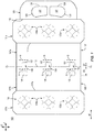
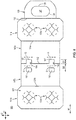
- Fig. 1 an exterior surface 101 of a base blank or lower blank or first blank 103 for forming a carrier 205 is illustrated according to a first exemplary embodiment of the disclosure.
- the first blank 103 can be provided in combination with a reinforcing blank or upper blank or second blank 203 ( Fig. 2 ) to form the carrier 205.
- the first blank 103 and the second blank 203 can be free from foldable connection to one another, though the blanks 103, 203 can be foldably connected without departing from the disclosure.
- the carrier 205 is sized to contain or support six containers, with three containers CA1, CA2, CA3 being attached to a front portion 206 of the carrier 205 and three containers CB1, CB2, CB3 being attached to a back portion 208 of the carrier 205.
- the front portion 206 and the back portion 208 of the carrier 205 can carry more or less than three containers without departing from the disclosure.
- the carrier 205 can be provided together with one or more containers as a package 210 ( Fig. 8 ).
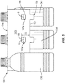
- the containers CA1, CA2, CA3, CB1, CB2, CB3 can be beverage bottles, for example, beverage bottles formed of a polymeric material such as polyethylene terephthalate (PET), with respective bottom portions B extending to a tapered upper neck portion N that terminates at a flange portion F upon which a cap CP is seated ( Fig. 3 ).
- PET polyethylene terephthalate
- the containers described herein could be any other suitable type and size of container without departing from the disclosure.
- the first blank 103 has a longitudinal axis L1 and a lateral axis L2.
- a grain direction M1 of the first blank 103 e.g., a direction along which the fibers/fibrous components of the material from which the first blank 103 is formed (e.g., paperboard) generally lie, can be generally parallel to the longitudinal axis L1. It will be understood that the grain direction M1 can be generally parallel to the lateral axis L2 or can be defined along a direction oblique relative to the longitudinal axis L1 without departing from the disclosure.
- the first blank 103 has a front portion 107 for at least partially forming the front portion 206 of the carrier 205, and a back portion 109 for at least partially forming the back portion 208 of the carrier 105.
- the front portion 107 and the back portion 109 of the first blank 103 are foldably connected at a lateral fold line 112 that forms a lateral centerline CL of the blank 103, as shown.
- the blank 103 is at least partially formed into the carrier 205 by folding the blank 103 at the fold line 112 along the centerline CL so that the front portion 107 and the back portion 109 of the blank 103 are overlapped in at least partial face-to-face contact. It will be understood that the designations of the portions 107, 109 of the blank 103 and the portions 106, 108 of the carrier 205 as respective "front” and “back” portions can be reversed without departing from the disclosure.
- the front portion 107 of the blank 103 comprises a handle panel 125 (broadly, "first handle panel”) having a pair of handle flaps 127 at interior portions thereof, each defined by a respective cut 128 and each foldably connected to the handle panel 125 at respective lateral fold line 129.
- the respective cuts 128 and the respective handle flaps 127 formed therefrom include one or more curved and/or oblique portions and extend from one endpoint of the respective fold line 129 to the other endpoint of the respective fold line 129, but can have a different configuration without departing from the disclosure.
- at least the handle panel 125 and/or the handle flaps 127 (and/or openings formed by the separation thereof) can be first handle features for at least partially forming a handle 251 of the carrier 205.
- a front container retention panel or front attachment panel 131a (broadly, “first attachment panel”) is foldably connected to the handle panel 125 at a lateral fold line 132a, and includes container retention features 133a for at least partially receiving and engaging the respective flange portions F and/or neck portions N of one or more of the containers CA1, CA2, CA3.
- Each container retention feature 133a includes a container receiving aperture or container receiving opening 135a that is defined by the arrangement of a plurality of container retention flaps 137a, each of which are defined by respective cuts 139a, and which are foldably connected to the attachment panel 131a at respective oblique fold lines 141a. It will be understood that a different configuration of the container retention features 133a, such as a different number of container retention flaps 137a, or a different configuration of features, can be provided without departing from the disclosure.
- a front central panel or front keel 147a is foldably connected to the attachment panel 131a at a lateral fold line 151a, and, as described further below, the front keel 147a is foldably connected to a back central panel or back keel 147b at the fold line 112.
- the fold line 112 is interrupted by and is collinear with a series of generally U-shaped cuts 157 to define a pair of protruding tabs 159 extending from the back portion 109 of the first blank 103 toward the front keel 147a.
- the tabs 159 separate from the front keel 147a to expose a pair of glue openings 167 (broadly, "front glue opening") along the front keel 147a ( Fig. 3 ).
- the back portion 109 of the blank 103 includes a back top panel or back container retention panel or back attachment panel 131b (broadly, “top container retention panel” or “top attachment panel” or “second attachment panel”) foldably connected to the back keel 147b at a lateral fold line 151b and having associated features that are generally a mirror-image of the corresponding panels and flaps of the front portion 107 of the blank 103.
- the details of the container retention features 133b of the back attachment panel 131b are shown best in Fig. IB.
- Corresponding components e.g., panels, flaps, fold lines, cuts, etc.
- corresponding reference numbers that differ by the "a” or "b" suffix, with the "a” components corresponding to the front portion 107 of the blank 103 and the "b" components corresponding to the back portion 109 of the blank 103.
- the back portion 109 of the blank 103 is shown without a handle panel attached thereto, it will be understood that a handle panel can be attached to the back attachment 131b, and/or another handle feature can be provided in the back portion 109 of the blank 103, without departing from the disclosure.
- the back keel 147b includes a series of glue openings 155 (broadly, "back glue opening”) each having a top edge that is spaced a greater longitudinal distance D2 from the fold line 112 than a longitudinal distance D1 from the fold line 112 at which a top edge of the cuts 157 are spaced.
- the top edge of the cuts 157 correspond to the top edge of the glue openings 167 upon separation of the tabs 159 from the keel 147a, as described further herein.
- any of the panels, flaps, fold lines, cuts, or other features could be otherwise shaped, arranged, and/or omitted from the blank 103 without departing from the disclosure.
- the blank 103 could be sized and/or shaped to accommodate more or less than six containers without departing from this disclosure.
- glue G can be applied to one or more portions of the respective keels 147a, 147b. While the glue G has been shown schematically on the exterior surface 101 of the blank 103 for positional reference, it will be understood that the glue G can be applied to the interior surface 102 of the blank 103, as described further herein.
- the glue G can have a foam or foamed configuration, e.g., such that pockets of fluids such as gas are interspersed with solid, semi-solid, and/or liquid components of adhesive.
- the glue G can be injected/infused with a fluid, e.g., gaseous, component that influences the glue G to expand from an originally-defined volume, over a change in time, to occupy a larger volume.
- the glue G can comprise about 50% solid/semi-solid/liquid adhesive and about 50% gaseous components.
- the glue G can comprise a different ratio of adhesive to gaseous components, for example, about 10% adhesive/about 90% gaseous components, about 20% adhesive/about 80% gaseous components, about 30% adhesive/about 70% gaseous components, about 40% adhesive/about 60% gaseous components, about 60% adhesive/about 40% gaseous components, about 70% adhesive/about 30% gaseous components, about 80% adhesive/about 20% gaseous components, about 90% adhesive/about 10% gaseous components, or other integer or non-integer percentage ratios therebetween.
- the glue G can be any suitable adhesive without departing from the disclosure.
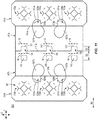
- a grain direction M2 of the second blank 203 can be generally parallel to the lateral axis L2, though the grain direction M2 can be generally parallel to the longitudinal axis L1 or can be defined along a direction oblique relative to the lateral axis L2 without departing from the disclosure.
- the second blank 203 includes a body or central panel 261 that includes a plurality of container retention features 233 that are substantially similar to the container retention features 133a, 133b, e.g., such that each container retention feature 233 includes the respective container receiving aperture or container receiving opening 235a that is defined by the arrangement of a plurality of respective container retention flaps 237a, each of which are defined by respective cuts 239a and are foldably connected to the central panel 261 at respective fold lines 241a, the features of which are best shown in Fig. 2A .
- a handle panel 225 (broadly, "second handle panel”) can be foldably connected to the central panel 261 at a fold line 231, and can have a configuration that is substantially similar to the handle panel 125 described above, e.g., such that each handle flap 127 is defined by the respective cut 128 and such that each handle flap 127 is foldably connected to the handle panel 225 at a respective lateral fold line 129.
- at least the handle panel 225 and/or the handle flaps 127 (and/or openings formed by the separation thereof) can be second handle features for at least partially forming a handle 251 of the carrier 205.
- the first blank 103 can be oriented with the exterior surface 101 facing downwardly and the exterior surface 102 facing upwardly, and the front attachment panel 131a and back attachment panel 131b can be lowered or otherwise brought into engagement with the respective containers CA1, CA2, CA3, CB1, CB2, CB3 such that respective top portions thereof that include at least the respective caps CP and respective flange portions F are at least partially received through the respective openings 135a, 135b of the respective container retention features 133a, 133b.
- Such engagement of the container retention features 133a, 133b with the respective containers CA1, CA2, CA3, CB1, CB2, CB2 can cause the respective container retention flaps 137a, 137b to separate from the respective attachment panel 131a, 131b and/or each other at the respective cuts 139a, 139b and to fold upwardly at the respective fold lines 141a, 141b.
- one or more of the container retention flaps 137a, 137b can rest against the neck portions N of the respective containers CA1, CA2, CA3, CB1, CB2, CB3 and distal edges thereof can be positioned to abut the respective flange portions F of the respective containers CA1, CA2, CA3, CB1, CB2, CB3.
- Portions of the respective container retention panel 131a, 131b adjacent the container retention flaps 137a, 137b can also be urged upwardly toward or into engagement with a portion of the respective containers CA1, CA2, CA3, CB1, CB2, CB3.
- the front keel 147a and the back keel 147b can be folded downwardly relative to the respective attachment panels 131a, 131b at the respective fold lines 151a, 151b and such that the keels 147a, 147b also fold at the fold line 112 as the keels 147a, 147b are moved into at least partial face-to-face contact in the direction of the respective arrows A1, A2.
- Such folding can draw the containers CA1, CA2, CA3 and CB1, CB2, CB3 toward each other in an arrangement separated by the overlapped keels 147a, 147b to at least partially define the front portion 206 of the carrier 205 and the back portion 208 of the carrier 205.
- the tabs 159 can separate from the front keel 147a at the respective cuts 157 to extend in a generally downward arrangement and such that series of discontinuities or front glue openings 167 can be defined along the front keel 147a.
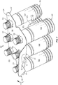
- the glue openings 167 of the front keel 147a are positioned to be longitudinally offset from the glue openings 155 of the back keel 147b, with a top edge of the glue openings 155 of the back keel 147b spaced the greater distance D2 ( Fig. 5 ) from the fold line 112 than the distance D2 ( Fig. 4 ) from the fold line 112 at which a top edge of the glue openings 167 of the front keel 147a are positioned.
- the glue openings 155 of the back keel 147b are positioned above the glue openings 167 of the front keel 147a such that the glue openings 167 expose respective portions of the back keel 147b and such that the glue openings 155 expose respective portions of the front keel 147a (shown best in Figs. 4 and 5 ).
- the above-described folded arrangement of the first blank 103 forms a first construct 104 that at least partially forms the carrier 205.
- the lines or other arrangements of glue G disposed along the front keel 147a and exposed at the glue openings 167 can adhere the containers CA1, CA2, CA3 to respective exposed portions of the back keel 147b, and lines of glue G exposed at the glue openings 155 of the back keel 147b can also adhere the containers CB1, CB2, CB3 to respective exposed portions of the front keel 147a.
- the glue G can also maintain the keels 147a, 147b in at least partial-face-to-face contact.
- the glue G and/or the glue openings 155, 167 could be otherwise shaped, arranged, positioned, and/or configured without departing from the disclosure.
- one or more of the glue openings 155, 167 can be provided with a circular or elliptical/ovoid configuration to provide clearance for radial expansion of the foamed glue G exposed therethrough.
- the edge of the keel 147b, 147a surrounding the respective glue opening 155, 167 can influence the expansion of the applied foamed glue G, for example, by promoting a generally bulbous/mushroom-shaped expansion of the foamed glue G outwardly from the respective keel 147b, 147a and radially away from the respective glue opening 155, 167.
- the glue G can be configured so as to not foam/expand upon application to the carrier 205.
- the attachment of the containers CA1, CA2, CA3, CB1, CB2, CB3 to the respective keels 147a, 147b can provide retention and support of the respective containers, e.g., such that the containers do not detach from the carrier 205 under their own weight, in addition to or alternative to the container retention and support provided by the respective container retention features 133a, 133b.
- one or more of the containers CA1, CA2, CA3, CB1, CB2, CB3 can be attached to respective keels 147a, 147b with glue G, without additional retention and support provided by an attachment panel as described above.
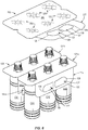
- the second blank 203 can be overlaid upon the first construct 104 in at least partial face-to-face contact therewith such that the container retention features 233 of the second blank 203 align with and overlie the respective container retention features 133a, 133b of the first construct 104.
- the above-described positioning of the second blank 203 on the first construct 104 forms a second construct 204 of the carrier 205.
- the container retention features 233 of the second construct 204 engage the respective containers CA1, CA2, CA3, CB1, CB2, CB3 in a manner similar to that described above with respect to the container retention features 133a, 133b.
- at least the respective caps CP and respective flange portions F of the respective containers CA1, CA2, CA3, CB1, CB2, CB3 are at least partially received through the respective openings 235 of the container retention features 233 and such that one or more of the container retention flaps 237 is urged by movement of the respective containers thereby to abut the neck portions N of the respective containers CA1, CA2, CA3, CB1, CB2, CB3, with the distal edges of the respective container retention flaps positioned to abut the respective flange portions F of the respective containers CA1, CA2, CA3, CB1, CB2, CB3.
- the handle panel 225 of the second construct 204 can be positioned to be aligned with and in at least partial face-to-face contact with the handle panel 125 of the first construct 104 to provide the multi-ply handle 251 of the carrier 205/package 210.
- the carrier 205/package 210 can be provided in a first or storage/shipping/retail configuration in which the handle panel 225 is folded downwardly relative to the central panel 261 and the attachment panels 131a, 131b.
- the aligned overlapped handle panels 225, 125 can be folded upwardly at the overlapped fold lines 233, 132 in the direction of the arrow A3 into an at least partially upright arrangement relative to the panels 261, 131a, 131b to define/present the handle 251 in a second or carrying configuration of the carrier 205/package 210.
- the containers that are positioned closest to the handle 251 can at least partially rest upon the respective containers that are positioned farthest from the handle 251.
- the containers are adhered to the keels 147a, 147b with glue G and are additionally secured to the attachment panels 131a, 131b and the central panel 261 through respective container retention features 133a, 133b, and 233.
- a consumer or other user can separate the respective handle flaps 127 from the handle panel 125 at the respective cuts 128 and can separate the respective handle flaps 227 from the handle panel 225 at the respective cuts 228 and can fold the respective handle flaps 127, 227 at the respective fold lines 129, 229 into at least partial overlapping/face-to-face contact with the handle panels 125, 225 to provide a four-ply arrangement of a portion of the handle 225, e.g., provided by the aligned arrangement of the handle flaps 127, 227 and respective portions of the handle panels 225, 125.
- the aforementioned combination of the first construct 104 and the second construct 204 provides a carrier 205/package 210 with a robust and rigid configuration provided by the overlapping first blank 103/construct 104 having the grain direction M1 and the second blank 203/second construct 204 having the grain direction M2 that is perpendicular to the grain direction M1 such that a cross-grain configuration is provided.
- Such cross-grain configuration of the carrier 205/package 210 can provide enhanced strengthening properties and resistance to tearing, e.g., since the carrier 205/package 210 is resistant to tearing in a direction perpendicular to the grain direction M1 as well as in a direction perpendicular to the grain direction M2.
- the cross-grain configuration of the carrier 205/package 210 is such that enhanced resistance to tearing is provided along two perpendicular axes.
- the package 210 described above provides a carrier 205 with a compact structure that can also, for example, provide materials savings and waste reduction. Additionally, the arrangement of the glue G between the containers and respective portions of the keels 247a, 247b, in addition to the engagement of the container retention features 133a, 133b, 233 with respective containers, provides multiple points of attachment that results in a robust structure for holding and carrying the containers.
- the exposure of one or more portions of the containers on exterior portions of the carrier 205/package 210 provides a consumer with a clear view of labeling or surface graphics associated with the containers as well as providing convenient access to remove one or more of the containers from the carrier 205/package 210, for example, by moving respective containers through the respective openings 135a, 135b, 235 of respective container retention features 133a, 133b, 233, and peeling a respective container away from the keels 147a, 147b as described above.
- the glue G can be selected from a material provided to remain on the respective keels 147a, 147b, e.g., such that substantially little or no glue G remains on the container as it is removed.
- One or more of the containers CA1, CA2, CA3, CB1, CB2, CB3, in one embodiment, can be reattached to the respective keels 147a, 147b following therefrom by pressing the container against a respective region of glue G.
- carrier 205/package 210 has been described as configured to hold three containers CA1, CA2, CA3, CB1, CB2, CB3 in a 2x3 arrangement, the carrier 205/package 210 could be otherwise shaped and configured to hold more or less than six containers in an alternative arrangement without departing from the scope of the disclosure.
- FIG. 8 an exterior surface 301 of a first blank 303 for forming a carrier 405 according to a second exemplary embodiment of the disclosure is illustrated.
- the first blank 303 can be combined with a second blank 403 ( Fig. 9 ) to form the carrier 405 ( Fig. 11 ).
- the first blank 303 and the second blank 403 can be free from foldable connection to one another, though the blanks 303, 403 can be foldably connected without departing from the disclosure.
- the carrier 405 can be provided in combination with one or more containers to form a package 410.
- the first blank 303 has one or more features that are substantially similar to those of the first blank 103 described above, and like or similar features are designated with like or similar reference numerals. As shown, the first blank 303 includes the handle panel 125, the front attachment panel 131a, the front keel 147a, the back keel 147b, and the back attachment panel 131b.
- the front attachment panel 131a includes a pair of the container retention features 133a for at least partially receiving a pair of containers CA1, CA2 and the back attachment panel 131b includes a pair of the container retention features 133b for at least partially receiving a pair of containers CB1, CB2.
- the handle panel 125 includes a single handle flap 127.
- FIG. 9 an exterior surface 401 of a reinforcing blank or upper blank or second blank 403 according to the second exemplary embodiment of the disclosure is illustrated.
- the second blank 403 has one or more features that are substantially similar to those of the second blank 203 described above, and like or similar features are designated with like or similar reference numerals.
- the second blank 403 includes the handle panel 225 and the central panel 261.
- the handle panel 225 can include a single handle flap 227, as shown, and the central panel 261 includes a plurality of the container retention features 233 for being aligned with the respective container retention features 133a, 133b of the first blank 303.
- a billboard or back panel 463 can be foldably connected to the central panel 261 at a lateral fold line 465, though the back panel 463 could be omitted without departing from the disclosure.
- the back panel 463 can provide a presentation surface that allows printing of indicia such as product advertising, labeling, promotional information, etc. that is readily visible to a consumer.
- the first blank 303 and/or the second blank 403 could be alternatively sized, shaped, and/or configured without departing from the scope of the disclosure.
- the first blank 303 can be folded in the manner described above with regard to the first blank 103, e.g., with the attachment panels 131a, 131b engaged with the containers CA1, CA2, CB1, CB2 via the respective container retention features 133a, 133b.
- the keels 147a, 147b are folded at the fold line 112 into at least partial face-to-face contact with one another such that the glue openings 155, 167 are arranged to be vertically offset from one another.
- each glue opening 155 is vertically spaced from each respective glue opening 167 such that respective portions of the back keel 147a are exposed through the respective glue openings 155 and such that respective portions of the front keel 147b are exposed through the respective glue openings 167.
- the attachment panels 131a, 131b extend away from the keels 147a, 147b in generally perpendicular relation thereto.
- the above-described arrangement of the first blank 303 forms a first construct 304 for at least partially forming the carrier 405.
- the second blank 403 can be overlaid upon the first construct 304 in at least partial face-to-face contact therewith such that the container retention features 233 of the second construct 404 align with and overlie the respective container retention features 133a, 133b of the first construct 304 to at least partially receive the containers CA1, CA2, CB1, CB2 in the manner described above with respect to the carrier 205/package 210.
- the above-described positioning of the second blank 403 upon the first construct 304 forms a second construct 404 of the carrier 405/package 410.
- the handle panel 225 of the second construct 204 is positioned in at least partial face-to-face contact with the handle panel 125 of the first construct 104 to provide a multi-ply handle 251 for the carrier 405/package 410.
- the handle 251 of the carrier 405/package 410 is positionable between a first or storage/shipping/retail configuration in which the handle 251 is folded downwardly relative to the central panel 261 and a second or carrying configuration in which the handle 251 is raised upwardly or is upright relative to the central panel 261 as described above with respect to the carrier 205/package 210.
- the configuration of the carrier 405/package 410 provides a compact and robust holding and carrying structure for the containers CA1, CA2, CB1, CB2 with the advantages described above with respect to the carrier 205/package 210.
- the grain direction M1 of the first blank 303 and the grain direction M2 of the second blank 403 that is perpendicular to the grain direction M1 provides a cross-grain configuration for the carrier 405/package 410 that is resistant to tearing along two perpendicular axes.
- carrier 405/package 410 has been described as configured to hold four containers CA1, CA2, CB1, CB2, in a 2x2 arrangement, the carrier 405/package 410 could be otherwise shaped and configured to hold more or less than four containers in an alternative arrangement without departing from the scope of the disclosure.
- Fig. 11 an exterior surface 501 of a first blank 503 for forming a carrier 605 according to a third exemplary embodiment of the disclosure is illustrated.
- the first blank 503 can be combined with a second blank 603 ( Fig. 12 ) to form the carrier 605 ( Fig. 13 ).
- the first blank 503 and the second blank 603 can be free from foldable connection to one another, though the blanks 503, 603 can be foldably connected without departing from the disclosure.
- the carrier 605 can be provided in combination with one or more containers to form a package 610.
- the first blank 503 has one or more features that are substantially similar to those of the first blanks 103, 303 described above, and like or similar features are designated with like or similar reference numerals. As shown, the first blank 503 includes the handle panel 125, the front attachment panel 131a, the front keel 147a, the back keel 147b, and the back attachment panel 131b.
- the front attachment panel 131a includes container retention features 133a for at least partially receiving respective containers CA1, CA2, CA3 and the back attachment panel 131b includes container retention features 133b for at least partially receiving respective containers CB1, CB2, CB3.
- a pair of finger or handle openings 527a are defined in the front keel 147a, and a pair of handle reinforcement flaps 528a are foldably connected to the front attachment panel 131a at a respective longitudinal fold line 529a.
- the handle reinforcement flaps 528a are at least partially defined by respective curved cuts 531a that extend from an endpoint of the respective fold line 529a to intersect a respective portion of the fold line 151a.
- a free edge of the respective handle reinforcement flaps 528a interrupts and is collinear with the fold line 151a, and is positioned abutting the respective handle openings 527a.
- a pair of finger or handle openings 527b are defined in the back keel 147b, and a pair of handle reinforcement flaps 528b are foldably connected to the back attachment panel 131b at a respective longitudinal fold line 529b.
- the handle reinforcement flaps 528b are at least partially defined by respective curved cuts 529b.
- at least the handle openings 527a, 527b and/or the handle reinforcement flaps 528a, 528b can form first handle features of the carrier 605.
- first blank 503 has been illustrated without a handle panel or a back panel, it will be understood that the first blank 503 can include a handle panel and/or a back panel without departing from the disclosure.
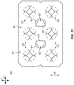
- FIG. 12 an exterior surface 601 of a reinforcing blank or upper blank or second blank 603 according to the third exemplary embodiment of the disclosure is illustrated.
- the second blank 603 has one or more features that are substantially similar to those of the second blanks 203, 403 described above, and like or similar features are designated with like or similar reference numerals.
- the second blank 603 includes the central panel 261 with container retention features 233 for being aligned with the respective container retention features 133a, 133b of the first blank 503.
- a pair of handle flaps 627 are foldably connected to the central panel 261 at respective lateral fold lines 629, and are at least partially defined by respective curved cuts 631 that extend from one endpoint of the respective fold line 629 to the other endpoint of the respective fold line 629. As described herein, at least the handle flaps 627 and/or openings formed from the separation thereof can form second handle features of the carrier 605.
- first blank 503 and/or the second blank 603 could be alternatively sized, shaped, and/or configured without departing from the scope of the disclosure.
- one or more of the handle flaps 627 and the handle reinforcement flaps 528a, 528b can include additional lines of weakening and/or relief cuts to facilitate movement and manipulation thereof by a consumer.
- the first blank 503 can be folded in the manner described above with regard to the first blanks 103, 303, e.g., with the attachment panels 131a, 131b engaged with the containers CA1, CA2, CA3, CB1, CB2, CB3 via the respective container retention features 133a, 133b.
- the keels 147a, 147b are folded at the fold line 112 into at least partial face-to-face contact with one another such that the glue openings 155, 167 are arranged to be vertically offset from one another.
- each glue opening 155 is vertically spaced from each respective glue opening 167 such that respective portions of the back keel 147a are exposed through the respective glue openings 155 and such that respective portions of the front keel 147b are exposed through the respective glue openings 167.
- the attachment panels 131a, 131b extend away from the keels 147a, 147b in generally perpendicular relation thereto.
- the above-described arrangement of the first blank 503 forms a first construct 504 for at least partially forming the carrier 605.
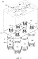
- the second blank 603 can be overlaid upon the first construct 504 in at least partial face-to-face contact therewith such that the container retention features 233 of the second blank 603 align with and overlie the respective container retention features 133a, 133b of the first construct 504 to at least partially receive the containers CA1, CA2, CA3, CB1, CB2, CB3 in the manner described above with respect to the carrier 205/package 210 and the carrier 405/package 410.
- the handle flaps 627 are positioned to be aligned with at least a portion of the respective handle openings 527a, 527b and/or the respective handle reinforcement flaps 528a, 528b. The above-described positioning of the second blank 603 on the first construct 405 forms a second construct 604 of the carrier 605.
- a consumer or other operator can separate one or both of the handle flaps 627 from the central panel 261 at a respective cut 631 and fold the respective handle flap 627 downwardly into a respective handle opening 527a, 527b aligned with the respective handle flap 627.
- a respective handle flap 528b can also be separated from the respective attachment panel 131a, 131b at a respective cut 529a, 529b and folded at a respective fold line 529a, 529b with the movement of the respective handle flap 627 to provide a two-ply structure that can, for example, cushion, protect, buffer etc.
- a consumer or other operator can engage the carrier 605/package 610 through an opening provided by at least one of the handle flaps 627 and can engage and edge or underside of a respective attachment panel 131a, 131b to lift, move, and/or carry the carrier 605/package 610.
- the configuration of the carrier 605/package 610 provides a compact and robust holding and carrying structure for the containers CA1, CA2, CA3, CB1, CB2, CB3 with the advantages described above with respect to the carrier 205/package 210 and carrier 405/package 410.
- the grain direction M1 of the first blank 503 and the grain direction M2 of the second blank 603 that is perpendicular to the grain direction M1 provides a cross-grain configuration for the carrier 605/package 610 that is resistant to tearing along two perpendicular axes.
- carrier 605/package 610 has been described as configured to hold six containers CA1, CA2, CA3, CB1, CB2, CB3 in a 2x3 arrangement, the carrier 605/package 610 could be otherwise shaped and configured to hold more or less than six containers in an alternative arrangement without departing from the scope of the disclosure.
- the blank may be constructed from paperboard having a caliper so that it is heavier and more rigid than ordinary paper.
- the blank can also be constructed of other materials, such as cardboard, or any other material having properties suitable for enabling the carrier to function at least generally as described above.
- the blank can be coated with, for example, a clay coating.
- the clay coating may then be printed over with product, advertising, and other information or images.
- the blanks may then be coated with a varnish to protect information printed on the blanks.
- the blanks may also be coated with, for example, a moisture barrier layer, on either or both sides of the blanks.
- the blanks can also be laminated to or coated with one or more sheet-like materials at selected panels or panel sections.
- a tear line can include: a slit that extends partially into the material along the desired line of weakness, and/or a series of spaced apart slits that extend partially into and/or completely through the material along the desired line of weakness, or various combinations of these features.
- one type tear line is in the form of a series of spaced apart slits that extend completely through the material, with adjacent slits being spaced apart slightly so that a nick (e.g., a small somewhat bridging-like piece of the material) is defined between the adjacent slits for typically temporarily connecting the material across the tear line. The nicks are broken during tearing along the tear line.
- the nicks typically are a relatively small percentage of the tear line, and alternatively the nicks can be omitted from or torn in a tear line such that the tear line is a continuous cut line. That is, it is within the scope of the present disclosure for each of the tear lines to be replaced with a continuous slit, or the like.
- a cut line can be a continuous slit or could be wider than a slit without departing from the present disclosure.
- a fold line can be any substantially linear, although not necessarily straight, form of weakening that facilitates folding therealong. More specifically, but not for the purpose of narrowing the scope of the present disclosure, fold lines include: a score line, such as lines formed with a blunt scoring knife, or the like, which creates a crushed or depressed portion in the material along the desired line of weakness; a cut that extends partially into a material along the desired line of weakness, and/or a series of cuts that extend partially into and/or completely through the material along the desired line of weakness; and various combinations of these features. In situations where cutting is used to create a fold line, typically the cutting will not be overly extensive in a manner that might cause a reasonable user to incorrectly consider the fold line to be a tear line.
- the above embodiments may be described as having one or more panels adhered together by glue during erection of the carrier embodiments.
- glue is intended to encompass all manner of adhesives commonly used to secure carrier panels in place.
Landscapes
- Engineering & Computer Science (AREA)
- Mechanical Engineering (AREA)
- Packages (AREA)
Applications Claiming Priority (2)
| Application Number | Priority Date | Filing Date | Title |
|---|---|---|---|
| US201962952839P | 2019-12-23 | 2019-12-23 | |
| US202062956882P | 2020-01-03 | 2020-01-03 |
Publications (1)
| Publication Number | Publication Date |
|---|---|
| EP3842360A1 true EP3842360A1 (fr) | 2021-06-30 |
Family
ID=70224278
Family Applications (1)
| Application Number | Title | Priority Date | Filing Date |
|---|---|---|---|
| EP20168268.9A Withdrawn EP3842360A1 (fr) | 2019-12-23 | 2020-04-06 | Support pour récipients |
Country Status (4)
| Country | Link |
|---|---|
| US (1) | US20210188511A1 (fr) |
| EP (1) | EP3842360A1 (fr) |
| BR (1) | BR112020015268A2 (fr) |
| WO (1) | WO2021133424A1 (fr) |
Cited By (4)
| Publication number | Priority date | Publication date | Assignee | Title |
|---|---|---|---|---|
| JP2022551866A (ja) * | 2019-10-10 | 2022-12-14 | グラフィック パッケージング インターナショナル エルエルシー | 容器用キャリア |
| EP3904235B1 (fr) * | 2020-04-27 | 2024-10-09 | Graphic Packaging International, LLC | Support pour récipients |
| EP4563489A1 (fr) * | 2023-11-28 | 2025-06-04 | Katholieke Universiteit Leuven | Support d'article pliable |
| US12503287B2 (en) | 2018-12-14 | 2025-12-23 | Graphic Packaging International, Llc | Carrier for containers |
Families Citing this family (2)
| Publication number | Priority date | Publication date | Assignee | Title |
|---|---|---|---|---|
| USD996981S1 (en) * | 2020-07-17 | 2023-08-29 | Fishbone Packaging Inc. | Container carrier |
| US12280903B2 (en) * | 2021-11-05 | 2025-04-22 | Illinois Tool Works Inc. | Container carrier |
Citations (7)
| Publication number | Priority date | Publication date | Assignee | Title |
|---|---|---|---|---|
| US5328024A (en) * | 1993-07-14 | 1994-07-12 | Riverwood International Corporation | Two-piece bottle carrier |
| US5485914A (en) * | 1994-11-08 | 1996-01-23 | Jefferson Smurfit Corporation | Composite article carrier |
| WO1996026128A1 (fr) * | 1995-02-23 | 1996-08-29 | Europa Carton Faltschachtel Gmbh | Support pour recipients |
| GB2321229A (en) * | 1997-01-17 | 1998-07-22 | Riverwood Int Corp | Paperboard bottle carrier device |
| US20100078337A1 (en) * | 2007-10-18 | 2010-04-01 | Sutherland Robert L | Package for container |
| DE102009059047A1 (de) * | 2009-12-14 | 2011-06-16 | Smurfit Kappa Baden Packaging Gmbh | Trägerverpackung für Flaschen |
| EP3666684A1 (fr) * | 2018-12-14 | 2020-06-17 | Graphic Packaging International, LLC | Support pour récipients |
Family Cites Families (4)
| Publication number | Priority date | Publication date | Assignee | Title |
|---|---|---|---|---|
| US4339032A (en) * | 1980-11-10 | 1982-07-13 | The Mead Corporation | Bottle carrier with peripheral skirt |
| IT1136923B (it) * | 1981-03-12 | 1986-09-03 | Gabriella Sommariva | Imballaggio per confezione multipla e procedimento per realizzare tale confezione multipla |
| US5487464A (en) * | 1993-12-20 | 1996-01-30 | Imperial Packaging, Inc. | Paperboard carrier with container release provision |
| US11124341B2 (en) * | 2017-10-19 | 2021-09-21 | Tommy L. Patton | Plastic bottle retaining apparatus and advertising platform |
-
2020
- 2020-03-25 WO PCT/US2020/024614 patent/WO2021133424A1/fr not_active Ceased
- 2020-03-25 US US16/829,346 patent/US20210188511A1/en not_active Abandoned
- 2020-03-25 BR BR112020015268A patent/BR112020015268A2/pt not_active IP Right Cessation
- 2020-04-06 EP EP20168268.9A patent/EP3842360A1/fr not_active Withdrawn
Patent Citations (7)
| Publication number | Priority date | Publication date | Assignee | Title |
|---|---|---|---|---|
| US5328024A (en) * | 1993-07-14 | 1994-07-12 | Riverwood International Corporation | Two-piece bottle carrier |
| US5485914A (en) * | 1994-11-08 | 1996-01-23 | Jefferson Smurfit Corporation | Composite article carrier |
| WO1996026128A1 (fr) * | 1995-02-23 | 1996-08-29 | Europa Carton Faltschachtel Gmbh | Support pour recipients |
| GB2321229A (en) * | 1997-01-17 | 1998-07-22 | Riverwood Int Corp | Paperboard bottle carrier device |
| US20100078337A1 (en) * | 2007-10-18 | 2010-04-01 | Sutherland Robert L | Package for container |
| DE102009059047A1 (de) * | 2009-12-14 | 2011-06-16 | Smurfit Kappa Baden Packaging Gmbh | Trägerverpackung für Flaschen |
| EP3666684A1 (fr) * | 2018-12-14 | 2020-06-17 | Graphic Packaging International, LLC | Support pour récipients |
Cited By (4)
| Publication number | Priority date | Publication date | Assignee | Title |
|---|---|---|---|---|
| US12503287B2 (en) | 2018-12-14 | 2025-12-23 | Graphic Packaging International, Llc | Carrier for containers |
| JP2022551866A (ja) * | 2019-10-10 | 2022-12-14 | グラフィック パッケージング インターナショナル エルエルシー | 容器用キャリア |
| EP3904235B1 (fr) * | 2020-04-27 | 2024-10-09 | Graphic Packaging International, LLC | Support pour récipients |
| EP4563489A1 (fr) * | 2023-11-28 | 2025-06-04 | Katholieke Universiteit Leuven | Support d'article pliable |
Also Published As
| Publication number | Publication date |
|---|---|
| BR112020015268A2 (pt) | 2022-09-13 |
| US20210188511A1 (en) | 2021-06-24 |
| WO2021133424A1 (fr) | 2021-07-01 |
Similar Documents
| Publication | Publication Date | Title |
|---|---|---|
| US11286094B2 (en) | Carrier for containers | |
| US11485555B2 (en) | Carrier for containers | |
| US11383907B2 (en) | Carrier for containers | |
| US11492185B2 (en) | Handled carrier for containers | |
| US11655088B2 (en) | Carrier for containers | |
| US12071290B2 (en) | Carrier for containers | |
| EP3666684A1 (fr) | Support pour récipients | |
| EP3842360A1 (fr) | Support pour récipients | |
| US11840387B2 (en) | Carrier for containers | |
| EP3666683A1 (fr) | Support pour récipients | |
| EP2401210B1 (fr) | SUPPORT POUR RÉCIPIENTS, FLAN ET PROCéDé POUR SA FABRICATION | |
| US8096413B2 (en) | Package for containers | |
| US20230303300A1 (en) | Carrier For Containers | |
| US12486092B2 (en) | Carrier for containers | |
| CA2719029C (fr) | Support pour recipients | |
| WO2020122984A1 (fr) | Support destiné à des récipients | |
| US20250376313A1 (en) | Carrier for containers |
Legal Events
| Date | Code | Title | Description |
|---|---|---|---|
| PUAI | Public reference made under article 153(3) epc to a published international application that has entered the european phase |
Free format text: ORIGINAL CODE: 0009012 |
|
| STAA | Information on the status of an ep patent application or granted ep patent |
Free format text: STATUS: THE APPLICATION HAS BEEN PUBLISHED |
|
| AK | Designated contracting states |
Kind code of ref document: A1 Designated state(s): AL AT BE BG CH CY CZ DE DK EE ES FI FR GB GR HR HU IE IS IT LI LT LU LV MC MK MT NL NO PL PT RO RS SE SI SK SM TR |
|
| STAA | Information on the status of an ep patent application or granted ep patent |
Free format text: STATUS: THE APPLICATION IS DEEMED TO BE WITHDRAWN |
|
| 18D | Application deemed to be withdrawn |
Effective date: 20220104 |