EP3842396A1 - Verbundglassatz und laminierte glasstruktur - Google Patents
Verbundglassatz und laminierte glasstruktur Download PDFInfo
- Publication number
- EP3842396A1 EP3842396A1 EP19851218.8A EP19851218A EP3842396A1 EP 3842396 A1 EP3842396 A1 EP 3842396A1 EP 19851218 A EP19851218 A EP 19851218A EP 3842396 A1 EP3842396 A1 EP 3842396A1
- Authority
- EP
- European Patent Office
- Prior art keywords
- interlayer film
- resin layer
- laminated glass
- distance
- film part
- Prior art date
- Legal status (The legal status is an assumption and is not a legal conclusion. Google has not performed a legal analysis and makes no representation as to the accuracy of the status listed.)
- Granted
Links
Images





Classifications
-
- B—PERFORMING OPERATIONS; TRANSPORTING
- B32—LAYERED PRODUCTS
- B32B—LAYERED PRODUCTS, i.e. PRODUCTS BUILT-UP OF STRATA OF FLAT OR NON-FLAT, e.g. CELLULAR OR HONEYCOMB, FORM
- B32B17/00—Layered products essentially comprising sheet glass, or glass, slag, or like fibres
- B32B17/06—Layered products essentially comprising sheet glass, or glass, slag, or like fibres comprising glass as the main or only constituent of a layer, next to another layer of a specific material
- B32B17/10—Layered products essentially comprising sheet glass, or glass, slag, or like fibres comprising glass as the main or only constituent of a layer, next to another layer of a specific material of synthetic resin
- B32B17/10005—Layered products essentially comprising sheet glass, or glass, slag, or like fibres comprising glass as the main or only constituent of a layer, next to another layer of a specific material of synthetic resin laminated safety glass or glazing
- B32B17/1055—Layered products essentially comprising sheet glass, or glass, slag, or like fibres comprising glass as the main or only constituent of a layer, next to another layer of a specific material of synthetic resin laminated safety glass or glazing characterized by the resin layer, i.e. interlayer
- B32B17/10651—Layered products essentially comprising sheet glass, or glass, slag, or like fibres comprising glass as the main or only constituent of a layer, next to another layer of a specific material of synthetic resin laminated safety glass or glazing characterized by the resin layer, i.e. interlayer comprising colorants, e.g. dyes or pigments
- B32B17/1066—Layered products essentially comprising sheet glass, or glass, slag, or like fibres comprising glass as the main or only constituent of a layer, next to another layer of a specific material of synthetic resin laminated safety glass or glazing characterized by the resin layer, i.e. interlayer comprising colorants, e.g. dyes or pigments imparting a tint in certain regions only, i.e. shade band
-
- B—PERFORMING OPERATIONS; TRANSPORTING
- B32—LAYERED PRODUCTS
- B32B—LAYERED PRODUCTS, i.e. PRODUCTS BUILT-UP OF STRATA OF FLAT OR NON-FLAT, e.g. CELLULAR OR HONEYCOMB, FORM
- B32B17/00—Layered products essentially comprising sheet glass, or glass, slag, or like fibres
- B32B17/06—Layered products essentially comprising sheet glass, or glass, slag, or like fibres comprising glass as the main or only constituent of a layer, next to another layer of a specific material
- B32B17/10—Layered products essentially comprising sheet glass, or glass, slag, or like fibres comprising glass as the main or only constituent of a layer, next to another layer of a specific material of synthetic resin
- B32B17/10005—Layered products essentially comprising sheet glass, or glass, slag, or like fibres comprising glass as the main or only constituent of a layer, next to another layer of a specific material of synthetic resin laminated safety glass or glazing
- B32B17/10009—Layered products essentially comprising sheet glass, or glass, slag, or like fibres comprising glass as the main or only constituent of a layer, next to another layer of a specific material of synthetic resin laminated safety glass or glazing characterized by the number, the constitution or treatment of glass sheets
- B32B17/10036—Layered products essentially comprising sheet glass, or glass, slag, or like fibres comprising glass as the main or only constituent of a layer, next to another layer of a specific material of synthetic resin laminated safety glass or glazing characterized by the number, the constitution or treatment of glass sheets comprising two outer glass sheets
-
- B—PERFORMING OPERATIONS; TRANSPORTING
- B32—LAYERED PRODUCTS
- B32B—LAYERED PRODUCTS, i.e. PRODUCTS BUILT-UP OF STRATA OF FLAT OR NON-FLAT, e.g. CELLULAR OR HONEYCOMB, FORM
- B32B17/00—Layered products essentially comprising sheet glass, or glass, slag, or like fibres
- B32B17/06—Layered products essentially comprising sheet glass, or glass, slag, or like fibres comprising glass as the main or only constituent of a layer, next to another layer of a specific material
- B32B17/10—Layered products essentially comprising sheet glass, or glass, slag, or like fibres comprising glass as the main or only constituent of a layer, next to another layer of a specific material of synthetic resin
- B32B17/10005—Layered products essentially comprising sheet glass, or glass, slag, or like fibres comprising glass as the main or only constituent of a layer, next to another layer of a specific material of synthetic resin laminated safety glass or glazing
- B32B17/10165—Functional features of the laminated safety glass or glazing
- B32B17/10293—Edge features, e.g. inserts or holes
-
- B—PERFORMING OPERATIONS; TRANSPORTING
- B32—LAYERED PRODUCTS
- B32B—LAYERED PRODUCTS, i.e. PRODUCTS BUILT-UP OF STRATA OF FLAT OR NON-FLAT, e.g. CELLULAR OR HONEYCOMB, FORM
- B32B17/00—Layered products essentially comprising sheet glass, or glass, slag, or like fibres
- B32B17/06—Layered products essentially comprising sheet glass, or glass, slag, or like fibres comprising glass as the main or only constituent of a layer, next to another layer of a specific material
- B32B17/10—Layered products essentially comprising sheet glass, or glass, slag, or like fibres comprising glass as the main or only constituent of a layer, next to another layer of a specific material of synthetic resin
- B32B17/10005—Layered products essentially comprising sheet glass, or glass, slag, or like fibres comprising glass as the main or only constituent of a layer, next to another layer of a specific material of synthetic resin laminated safety glass or glazing
- B32B17/10165—Functional features of the laminated safety glass or glazing
- B32B17/10339—Specific parts of the laminated safety glass or glazing being colored or tinted
- B32B17/10357—Specific parts of the laminated safety glass or glazing being colored or tinted comprising a tinted intermediate film
-
- B—PERFORMING OPERATIONS; TRANSPORTING
- B32—LAYERED PRODUCTS
- B32B—LAYERED PRODUCTS, i.e. PRODUCTS BUILT-UP OF STRATA OF FLAT OR NON-FLAT, e.g. CELLULAR OR HONEYCOMB, FORM
- B32B17/00—Layered products essentially comprising sheet glass, or glass, slag, or like fibres
- B32B17/06—Layered products essentially comprising sheet glass, or glass, slag, or like fibres comprising glass as the main or only constituent of a layer, next to another layer of a specific material
- B32B17/10—Layered products essentially comprising sheet glass, or glass, slag, or like fibres comprising glass as the main or only constituent of a layer, next to another layer of a specific material of synthetic resin
- B32B17/10005—Layered products essentially comprising sheet glass, or glass, slag, or like fibres comprising glass as the main or only constituent of a layer, next to another layer of a specific material of synthetic resin laminated safety glass or glazing
- B32B17/1055—Layered products essentially comprising sheet glass, or glass, slag, or like fibres comprising glass as the main or only constituent of a layer, next to another layer of a specific material of synthetic resin laminated safety glass or glazing characterized by the resin layer, i.e. interlayer
- B32B17/10614—Layered products essentially comprising sheet glass, or glass, slag, or like fibres comprising glass as the main or only constituent of a layer, next to another layer of a specific material of synthetic resin laminated safety glass or glazing characterized by the resin layer, i.e. interlayer comprising particles for purposes other than dyeing
- B32B17/10633—Infrared radiation absorbing or reflecting agents
-
- B—PERFORMING OPERATIONS; TRANSPORTING
- B32—LAYERED PRODUCTS
- B32B—LAYERED PRODUCTS, i.e. PRODUCTS BUILT-UP OF STRATA OF FLAT OR NON-FLAT, e.g. CELLULAR OR HONEYCOMB, FORM
- B32B17/00—Layered products essentially comprising sheet glass, or glass, slag, or like fibres
- B32B17/06—Layered products essentially comprising sheet glass, or glass, slag, or like fibres comprising glass as the main or only constituent of a layer, next to another layer of a specific material
- B32B17/10—Layered products essentially comprising sheet glass, or glass, slag, or like fibres comprising glass as the main or only constituent of a layer, next to another layer of a specific material of synthetic resin
- B32B17/10005—Layered products essentially comprising sheet glass, or glass, slag, or like fibres comprising glass as the main or only constituent of a layer, next to another layer of a specific material of synthetic resin laminated safety glass or glazing
- B32B17/1055—Layered products essentially comprising sheet glass, or glass, slag, or like fibres comprising glass as the main or only constituent of a layer, next to another layer of a specific material of synthetic resin laminated safety glass or glazing characterized by the resin layer, i.e. interlayer
- B32B17/10761—Layered products essentially comprising sheet glass, or glass, slag, or like fibres comprising glass as the main or only constituent of a layer, next to another layer of a specific material of synthetic resin laminated safety glass or glazing characterized by the resin layer, i.e. interlayer containing vinyl acetal
-
- B—PERFORMING OPERATIONS; TRANSPORTING
- B32—LAYERED PRODUCTS
- B32B—LAYERED PRODUCTS, i.e. PRODUCTS BUILT-UP OF STRATA OF FLAT OR NON-FLAT, e.g. CELLULAR OR HONEYCOMB, FORM
- B32B27/00—Layered products comprising a layer of synthetic resin
- B32B27/06—Layered products comprising a layer of synthetic resin as the main or only constituent of a layer, which is next to another layer of the same or of a different material
- B32B27/08—Layered products comprising a layer of synthetic resin as the main or only constituent of a layer, which is next to another layer of the same or of a different material of synthetic resin
-
- B—PERFORMING OPERATIONS; TRANSPORTING
- B32—LAYERED PRODUCTS
- B32B—LAYERED PRODUCTS, i.e. PRODUCTS BUILT-UP OF STRATA OF FLAT OR NON-FLAT, e.g. CELLULAR OR HONEYCOMB, FORM
- B32B27/00—Layered products comprising a layer of synthetic resin
- B32B27/18—Layered products comprising a layer of synthetic resin characterised by the use of special additives
-
- B—PERFORMING OPERATIONS; TRANSPORTING
- B32—LAYERED PRODUCTS
- B32B—LAYERED PRODUCTS, i.e. PRODUCTS BUILT-UP OF STRATA OF FLAT OR NON-FLAT, e.g. CELLULAR OR HONEYCOMB, FORM
- B32B27/00—Layered products comprising a layer of synthetic resin
- B32B27/18—Layered products comprising a layer of synthetic resin characterised by the use of special additives
- B32B27/20—Layered products comprising a layer of synthetic resin characterised by the use of special additives using fillers, pigments, thixotroping agents
-
- B—PERFORMING OPERATIONS; TRANSPORTING
- B32—LAYERED PRODUCTS
- B32B—LAYERED PRODUCTS, i.e. PRODUCTS BUILT-UP OF STRATA OF FLAT OR NON-FLAT, e.g. CELLULAR OR HONEYCOMB, FORM
- B32B3/00—Layered products comprising a layer with external or internal discontinuities or unevennesses, or a layer of non-planar shape; Layered products comprising a layer having particular features of form
- B32B3/02—Layered products comprising a layer with external or internal discontinuities or unevennesses, or a layer of non-planar shape; Layered products comprising a layer having particular features of form characterised by features of form at particular places, e.g. in edge regions
- B32B3/06—Layered products comprising a layer with external or internal discontinuities or unevennesses, or a layer of non-planar shape; Layered products comprising a layer having particular features of form characterised by features of form at particular places, e.g. in edge regions for securing layers together; for attaching the product to another member, e.g. to a support, or to another product, e.g. groove/tongue, interlocking
-
- B—PERFORMING OPERATIONS; TRANSPORTING
- B32—LAYERED PRODUCTS
- B32B—LAYERED PRODUCTS, i.e. PRODUCTS BUILT-UP OF STRATA OF FLAT OR NON-FLAT, e.g. CELLULAR OR HONEYCOMB, FORM
- B32B3/00—Layered products comprising a layer with external or internal discontinuities or unevennesses, or a layer of non-planar shape; Layered products comprising a layer having particular features of form
- B32B3/26—Layered products comprising a layer with external or internal discontinuities or unevennesses, or a layer of non-planar shape; Layered products comprising a layer having particular features of form characterised by a particular shape of the outline of the cross-section of a continuous layer; characterised by a layer with cavities or internal voids ; characterised by an apertured layer
- B32B3/263—Layered products comprising a layer with external or internal discontinuities or unevennesses, or a layer of non-planar shape; Layered products comprising a layer having particular features of form characterised by a particular shape of the outline of the cross-section of a continuous layer; characterised by a layer with cavities or internal voids ; characterised by an apertured layer characterised by a layer having non-uniform thickness
-
- B—PERFORMING OPERATIONS; TRANSPORTING
- B32—LAYERED PRODUCTS
- B32B—LAYERED PRODUCTS, i.e. PRODUCTS BUILT-UP OF STRATA OF FLAT OR NON-FLAT, e.g. CELLULAR OR HONEYCOMB, FORM
- B32B5/00—Layered products characterised by the non- homogeneity or physical structure, i.e. comprising a fibrous, filamentary, particulate or foam layer; Layered products characterised by having a layer differing constitutionally or physically in different parts
- B32B5/14—Layered products characterised by the non- homogeneity or physical structure, i.e. comprising a fibrous, filamentary, particulate or foam layer; Layered products characterised by having a layer differing constitutionally or physically in different parts characterised by a layer differing constitutionally or physically in different parts, e.g. denser near its faces
- B32B5/142—Variation across the area of the layer
-
- B—PERFORMING OPERATIONS; TRANSPORTING
- B32—LAYERED PRODUCTS
- B32B—LAYERED PRODUCTS, i.e. PRODUCTS BUILT-UP OF STRATA OF FLAT OR NON-FLAT, e.g. CELLULAR OR HONEYCOMB, FORM
- B32B5/00—Layered products characterised by the non- homogeneity or physical structure, i.e. comprising a fibrous, filamentary, particulate or foam layer; Layered products characterised by having a layer differing constitutionally or physically in different parts
- B32B5/14—Layered products characterised by the non- homogeneity or physical structure, i.e. comprising a fibrous, filamentary, particulate or foam layer; Layered products characterised by having a layer differing constitutionally or physically in different parts characterised by a layer differing constitutionally or physically in different parts, e.g. denser near its faces
- B32B5/145—Variation across the thickness of the layer
-
- B—PERFORMING OPERATIONS; TRANSPORTING
- B32—LAYERED PRODUCTS
- B32B—LAYERED PRODUCTS, i.e. PRODUCTS BUILT-UP OF STRATA OF FLAT OR NON-FLAT, e.g. CELLULAR OR HONEYCOMB, FORM
- B32B7/00—Layered products characterised by the relation between layers; Layered products characterised by the relative orientation of features between layers, or by the relative values of a measurable parameter between layers, i.e. products comprising layers having different physical, chemical or physicochemical properties; Layered products characterised by the interconnection of layers
- B32B7/02—Physical, chemical or physicochemical properties
- B32B7/023—Optical properties
-
- B—PERFORMING OPERATIONS; TRANSPORTING
- B32—LAYERED PRODUCTS
- B32B—LAYERED PRODUCTS, i.e. PRODUCTS BUILT-UP OF STRATA OF FLAT OR NON-FLAT, e.g. CELLULAR OR HONEYCOMB, FORM
- B32B2250/00—Layers arrangement
- B32B2250/03—3 layers
-
- B—PERFORMING OPERATIONS; TRANSPORTING
- B32—LAYERED PRODUCTS
- B32B—LAYERED PRODUCTS, i.e. PRODUCTS BUILT-UP OF STRATA OF FLAT OR NON-FLAT, e.g. CELLULAR OR HONEYCOMB, FORM
- B32B2250/00—Layers arrangement
- B32B2250/05—5 or more layers
-
- B—PERFORMING OPERATIONS; TRANSPORTING
- B32—LAYERED PRODUCTS
- B32B—LAYERED PRODUCTS, i.e. PRODUCTS BUILT-UP OF STRATA OF FLAT OR NON-FLAT, e.g. CELLULAR OR HONEYCOMB, FORM
- B32B2250/00—Layers arrangement
- B32B2250/40—Symmetrical or sandwich layers, e.g. ABA, ABCBA, ABCCBA
-
- B—PERFORMING OPERATIONS; TRANSPORTING
- B32—LAYERED PRODUCTS
- B32B—LAYERED PRODUCTS, i.e. PRODUCTS BUILT-UP OF STRATA OF FLAT OR NON-FLAT, e.g. CELLULAR OR HONEYCOMB, FORM
- B32B2255/00—Coating on the layer surface
- B32B2255/06—Coating on the layer surface on metal layer
-
- B—PERFORMING OPERATIONS; TRANSPORTING
- B32—LAYERED PRODUCTS
- B32B—LAYERED PRODUCTS, i.e. PRODUCTS BUILT-UP OF STRATA OF FLAT OR NON-FLAT, e.g. CELLULAR OR HONEYCOMB, FORM
- B32B2255/00—Coating on the layer surface
- B32B2255/20—Inorganic coating
-
- B—PERFORMING OPERATIONS; TRANSPORTING
- B32—LAYERED PRODUCTS
- B32B—LAYERED PRODUCTS, i.e. PRODUCTS BUILT-UP OF STRATA OF FLAT OR NON-FLAT, e.g. CELLULAR OR HONEYCOMB, FORM
- B32B2255/00—Coating on the layer surface
- B32B2255/20—Inorganic coating
- B32B2255/205—Metallic coating
-
- B—PERFORMING OPERATIONS; TRANSPORTING
- B32—LAYERED PRODUCTS
- B32B—LAYERED PRODUCTS, i.e. PRODUCTS BUILT-UP OF STRATA OF FLAT OR NON-FLAT, e.g. CELLULAR OR HONEYCOMB, FORM
- B32B2264/00—Composition or properties of particles which form a particulate layer or are present as additives
- B32B2264/02—Synthetic macromolecular particles
- B32B2264/0214—Particles made of materials belonging to B32B27/00
-
- B—PERFORMING OPERATIONS; TRANSPORTING
- B32—LAYERED PRODUCTS
- B32B—LAYERED PRODUCTS, i.e. PRODUCTS BUILT-UP OF STRATA OF FLAT OR NON-FLAT, e.g. CELLULAR OR HONEYCOMB, FORM
- B32B2264/00—Composition or properties of particles which form a particulate layer or are present as additives
- B32B2264/10—Inorganic particles
- B32B2264/101—Glass
-
- B—PERFORMING OPERATIONS; TRANSPORTING
- B32—LAYERED PRODUCTS
- B32B—LAYERED PRODUCTS, i.e. PRODUCTS BUILT-UP OF STRATA OF FLAT OR NON-FLAT, e.g. CELLULAR OR HONEYCOMB, FORM
- B32B2264/00—Composition or properties of particles which form a particulate layer or are present as additives
- B32B2264/10—Inorganic particles
- B32B2264/102—Oxide or hydroxide
-
- B—PERFORMING OPERATIONS; TRANSPORTING
- B32—LAYERED PRODUCTS
- B32B—LAYERED PRODUCTS, i.e. PRODUCTS BUILT-UP OF STRATA OF FLAT OR NON-FLAT, e.g. CELLULAR OR HONEYCOMB, FORM
- B32B2264/00—Composition or properties of particles which form a particulate layer or are present as additives
- B32B2264/10—Inorganic particles
- B32B2264/104—Oxysalt, e.g. carbonate, sulfate, phosphate or nitrate particles
-
- B—PERFORMING OPERATIONS; TRANSPORTING
- B32—LAYERED PRODUCTS
- B32B—LAYERED PRODUCTS, i.e. PRODUCTS BUILT-UP OF STRATA OF FLAT OR NON-FLAT, e.g. CELLULAR OR HONEYCOMB, FORM
- B32B2264/00—Composition or properties of particles which form a particulate layer or are present as additives
- B32B2264/10—Inorganic particles
- B32B2264/107—Ceramic
- B32B2264/108—Carbon, e.g. graphite particles
-
- B—PERFORMING OPERATIONS; TRANSPORTING
- B32—LAYERED PRODUCTS
- B32B—LAYERED PRODUCTS, i.e. PRODUCTS BUILT-UP OF STRATA OF FLAT OR NON-FLAT, e.g. CELLULAR OR HONEYCOMB, FORM
- B32B2264/00—Composition or properties of particles which form a particulate layer or are present as additives
- B32B2264/12—Mixture of at least two particles made of different materials
-
- B—PERFORMING OPERATIONS; TRANSPORTING
- B32—LAYERED PRODUCTS
- B32B—LAYERED PRODUCTS, i.e. PRODUCTS BUILT-UP OF STRATA OF FLAT OR NON-FLAT, e.g. CELLULAR OR HONEYCOMB, FORM
- B32B2264/00—Composition or properties of particles which form a particulate layer or are present as additives
- B32B2264/50—Particles characterised by their position or distribution in a layer
- B32B2264/502—Particles characterised by their position or distribution in a layer distributed in a gradient manner
-
- B—PERFORMING OPERATIONS; TRANSPORTING
- B32—LAYERED PRODUCTS
- B32B—LAYERED PRODUCTS, i.e. PRODUCTS BUILT-UP OF STRATA OF FLAT OR NON-FLAT, e.g. CELLULAR OR HONEYCOMB, FORM
- B32B2270/00—Resin or rubber layer containing a blend of at least two different polymers
-
- B—PERFORMING OPERATIONS; TRANSPORTING
- B32—LAYERED PRODUCTS
- B32B—LAYERED PRODUCTS, i.e. PRODUCTS BUILT-UP OF STRATA OF FLAT OR NON-FLAT, e.g. CELLULAR OR HONEYCOMB, FORM
- B32B2307/00—Properties of the layers or laminate
- B32B2307/10—Properties of the layers or laminate having particular acoustical properties
- B32B2307/102—Insulating
-
- B—PERFORMING OPERATIONS; TRANSPORTING
- B32—LAYERED PRODUCTS
- B32B—LAYERED PRODUCTS, i.e. PRODUCTS BUILT-UP OF STRATA OF FLAT OR NON-FLAT, e.g. CELLULAR OR HONEYCOMB, FORM
- B32B2307/00—Properties of the layers or laminate
- B32B2307/20—Properties of the layers or laminate having particular electrical or magnetic properties, e.g. piezoelectric
- B32B2307/204—Di-electric
-
- B—PERFORMING OPERATIONS; TRANSPORTING
- B32—LAYERED PRODUCTS
- B32B—LAYERED PRODUCTS, i.e. PRODUCTS BUILT-UP OF STRATA OF FLAT OR NON-FLAT, e.g. CELLULAR OR HONEYCOMB, FORM
- B32B2307/00—Properties of the layers or laminate
- B32B2307/30—Properties of the layers or laminate having particular thermal properties
- B32B2307/306—Resistant to heat
-
- B—PERFORMING OPERATIONS; TRANSPORTING
- B32—LAYERED PRODUCTS
- B32B—LAYERED PRODUCTS, i.e. PRODUCTS BUILT-UP OF STRATA OF FLAT OR NON-FLAT, e.g. CELLULAR OR HONEYCOMB, FORM
- B32B2307/00—Properties of the layers or laminate
- B32B2307/40—Properties of the layers or laminate having particular optical properties
- B32B2307/402—Coloured
- B32B2307/4026—Coloured within the layer by addition of a colorant, e.g. pigments, dyes
-
- B—PERFORMING OPERATIONS; TRANSPORTING
- B32—LAYERED PRODUCTS
- B32B—LAYERED PRODUCTS, i.e. PRODUCTS BUILT-UP OF STRATA OF FLAT OR NON-FLAT, e.g. CELLULAR OR HONEYCOMB, FORM
- B32B2307/00—Properties of the layers or laminate
- B32B2307/40—Properties of the layers or laminate having particular optical properties
- B32B2307/412—Transparent
-
- B—PERFORMING OPERATIONS; TRANSPORTING
- B32—LAYERED PRODUCTS
- B32B—LAYERED PRODUCTS, i.e. PRODUCTS BUILT-UP OF STRATA OF FLAT OR NON-FLAT, e.g. CELLULAR OR HONEYCOMB, FORM
- B32B2307/00—Properties of the layers or laminate
- B32B2307/40—Properties of the layers or laminate having particular optical properties
- B32B2307/416—Reflective
-
- B—PERFORMING OPERATIONS; TRANSPORTING
- B32—LAYERED PRODUCTS
- B32B—LAYERED PRODUCTS, i.e. PRODUCTS BUILT-UP OF STRATA OF FLAT OR NON-FLAT, e.g. CELLULAR OR HONEYCOMB, FORM
- B32B2307/00—Properties of the layers or laminate
- B32B2307/40—Properties of the layers or laminate having particular optical properties
- B32B2307/418—Refractive
-
- B—PERFORMING OPERATIONS; TRANSPORTING
- B32—LAYERED PRODUCTS
- B32B—LAYERED PRODUCTS, i.e. PRODUCTS BUILT-UP OF STRATA OF FLAT OR NON-FLAT, e.g. CELLULAR OR HONEYCOMB, FORM
- B32B2307/00—Properties of the layers or laminate
- B32B2307/50—Properties of the layers or laminate having particular mechanical properties
- B32B2307/546—Flexural strength; Flexion stiffness
-
- B—PERFORMING OPERATIONS; TRANSPORTING
- B32—LAYERED PRODUCTS
- B32B—LAYERED PRODUCTS, i.e. PRODUCTS BUILT-UP OF STRATA OF FLAT OR NON-FLAT, e.g. CELLULAR OR HONEYCOMB, FORM
- B32B2307/00—Properties of the layers or laminate
- B32B2307/70—Other properties
- B32B2307/732—Dimensional properties
-
- B—PERFORMING OPERATIONS; TRANSPORTING
- B32—LAYERED PRODUCTS
- B32B—LAYERED PRODUCTS, i.e. PRODUCTS BUILT-UP OF STRATA OF FLAT OR NON-FLAT, e.g. CELLULAR OR HONEYCOMB, FORM
- B32B2307/00—Properties of the layers or laminate
- B32B2307/70—Other properties
- B32B2307/75—Printability
-
- B—PERFORMING OPERATIONS; TRANSPORTING
- B32—LAYERED PRODUCTS
- B32B—LAYERED PRODUCTS, i.e. PRODUCTS BUILT-UP OF STRATA OF FLAT OR NON-FLAT, e.g. CELLULAR OR HONEYCOMB, FORM
- B32B2419/00—Buildings or parts thereof
-
- B—PERFORMING OPERATIONS; TRANSPORTING
- B32—LAYERED PRODUCTS
- B32B—LAYERED PRODUCTS, i.e. PRODUCTS BUILT-UP OF STRATA OF FLAT OR NON-FLAT, e.g. CELLULAR OR HONEYCOMB, FORM
- B32B2605/00—Vehicles
- B32B2605/08—Cars
-
- B—PERFORMING OPERATIONS; TRANSPORTING
- B32—LAYERED PRODUCTS
- B32B—LAYERED PRODUCTS, i.e. PRODUCTS BUILT-UP OF STRATA OF FLAT OR NON-FLAT, e.g. CELLULAR OR HONEYCOMB, FORM
- B32B2605/00—Vehicles
- B32B2605/10—Trains
-
- B—PERFORMING OPERATIONS; TRANSPORTING
- B32—LAYERED PRODUCTS
- B32B—LAYERED PRODUCTS, i.e. PRODUCTS BUILT-UP OF STRATA OF FLAT OR NON-FLAT, e.g. CELLULAR OR HONEYCOMB, FORM
- B32B2605/00—Vehicles
- B32B2605/12—Ships
-
- B—PERFORMING OPERATIONS; TRANSPORTING
- B32—LAYERED PRODUCTS
- B32B—LAYERED PRODUCTS, i.e. PRODUCTS BUILT-UP OF STRATA OF FLAT OR NON-FLAT, e.g. CELLULAR OR HONEYCOMB, FORM
- B32B2605/00—Vehicles
- B32B2605/18—Aircraft
Definitions
- the present invention relates to a laminated glass set including an interlayer film for laminated glass having a gradation pattern. Moreover, the present invention relates to a laminated glass structure prepared with the laminated glass set.
- Laminated glass in which an interlayer film for laminated glass is sandwiched between a pair of glass plates is known.
- the laminated glass is widely used for automobiles, railway vehicles, aircraft, ships, buildings and the like.
- laminated glass having privacy protectability is requested as laminated glass for buildings.
- laminated glass having privacy protectability for example, there is a region where a person or an object located behind the laminated glass is invisible although the region can transmit light.
- Patent Document 1 discloses a laminated glass prepared with a multilayer interlayer film having an opaque layer.
- privacy protectability is achieved by the opaque layer that makes a person or an object located behind the laminated glass invisible.
- Patent Document 1 faces the problem that the appearance designability is poor because the whole surface of the glass has the same color.
- Patent Documents 2 and 3 disclose a laminated glass prepared with an interlayer film having a gradation pattern.
- the interlayer films in Patent Documents 2 and 3 are provided with appearance designability by a gradation pattern.
- the interlayer films as described in Patent Documents 2 and 3 are often formed by extrusion molding.
- the extruded interlayer film has a long shape, and has a lengthwise direction and a widthwise direction.
- a gradation pattern in which the color tone varies is provided in the direction connecting one end and the other end in the widthwise direction.
- the extruded interlayer film can be wound into a roll shape to form a roll body before production of laminated glass.
- the interlayer film is cut at predetermined intervals in the lengthwise direction at the time of production of laminated glass. Then, each of the plurality of cut interlayer films is arranged between two glass plates, and thus a plurality of laminated glasses are produced.
- the present inventors made diligent efforts, and found that in conventional interlayer films, the width of the region where a gradation pattern is provided varies in the lengthwise direction of the interlayer film.
- the present inventors found that the width of the region provided with a gradation pattern varies in a plurality of laminated glasses produced by using a plurality of cut interlayer films.
- a conventional interlayer film provided with a gradation pattern is frequently used for providing a windshield for vehicle with anti-glare property.
- the lengths of the interlayer film and the laminated glass are limited, so that it is relatively rare that variation in the width of the region where the gradation pattern is provided is problematic.
- laminated glass when laminated glass is used as handrail glass, several to several tens of laminated glasses are arranged in line.
- variation in the width of the region where the gradation pattern is provided in the interlayer film becomes obvious, and in a structure in which a plurality of the laminated glasses are arranged in line, the appearance designability is impaired due to partial misalignment in color width of the gradation pattern or the like.
- a laminated glass set that is a set of a plurality of laminated glasses, each of the plurality of laminated glasses including a first lamination glass member, a second lamination glass member, and an interlayer film part arranged between the first lamination glass member and the second lamination glass member, the interlayer film part having one end, and the other end at the opposite side of the one end, the interlayer film part having a colored part, the colored part having a gradation part where visible light transmittance increases from the one end side toward the other end side of the interlayer film part, the gradation part forming a tip of the colored part on the other end side of the interlayer film part, when distance X from the one end of the interlayer film part to a tip of the colored part on the other end side of the interlayer film part is measured in each of the plurality of laminated glasses, a maximum value of distance X is denoted by X max , a minimum value of distance X is denoted by
- the laminated glass set satisfies the formula (1).
- the X min is 0.6 m or more.
- a tip of the colored part on the one end side of the interlayer film part reaches the one end of the interlayer film part.
- the laminated glass set satisfies the formula (2).
- the Y min is 0.6 m or more.
- the laminated glass set when distance Z of the gradation part in the direction connecting the one end and the other end of the interlayer film part is measured in each of the plurality of laminated glasses, a maximum value of distance Z is denoted by Z max , a minimum value of distance Z is denoted by Z min , and an average value of distance Z is denoted by Z ave , the laminated glass set satisfies the following formula (3).
- the interlayer film part includes a first resin layer and a second resin layer, the first resin layer is arranged on a first surface side of the second resin layer, the second resin layer contains a coloring agent, and the second resin layer forms the colored part.
- the coloring agent includes calcium carbonate particles.
- the first resin layer is arranged on a second surface opposite to the first surface of the second resin layer.
- the colored part has a dark color part having uniform visible light transmittance from the one end side toward the other end side of the interlayer film part, and in the interlayer film part, the dark color part is located closer to the one end of the interlayer film part than the gradation part.
- a laminated glass structure comprising the laminated glass set as described above, and a connecting member that connects the plurality of laminated glasses in the laminated glass set.
- a laminated glass set according to the present invention is a set of a plurality of laminated glasses.
- each of the plurality of laminated glasses includes a first lamination glass member, a second lamination glass member, and an interlayer film part arranged between the first lamination glass member and the second lamination glass member.
- the interlayer film part has one end, and the other end at the opposite side of the one end.
- the interlayer film part has a colored part.
- the colored part has a gradation part where visible light transmittance increases from the one end side toward the other end side of the interlayer film part, and the gradation part forms a tip of the colored part on the other end side of the interlayer film part.
- distance X from the one end of the interlayer film part to a tip of the colored part on the other end side of the interlayer film part is measured, a maximum value of distance X is denoted by X max , a minimum value of distance X is denoted by X min , and an average value of distance X is denoted by X ave .
- each of the plurality of laminated glasses distance Y of the colored part in the direction connecting the one end and the other end of the interlayer film part is measured, a maximum value of distance Y is denoted by Y max , a minimum value of distance Y is denoted by Y min , and an average value of distance Y is denoted by Y ave .
- the laminated glass set according to the present invention satisfies the above formula (1) or satisfies the above formula (2).
- the laminated glass set according to the present invention is excellent in appearance designability because the aforementioned general configuration is provided.
- a laminated glass set according to the present invention is a set of a plurality of laminated glasses.
- a laminated glass included in one set of the laminated glass set corresponds to one laminated glass included in the later-described laminated glass structure.
- each of the plurality of laminated glasses includes a first lamination glass member, a second lamination glass member, and an interlayer film part arranged between the first lamination glass member and the second lamination glass member.
- the interlayer film part has one end, and the other end at the opposite side of the one end.
- the one end and the other end are end parts of both sides facing each other in the interlayer film part.
- the interlayer film part has a colored part.
- the colored part extends from one end side toward the other end side of the interlayer film part.
- the colored part has a gradation part where visible light transmittance increases from the one end side toward the other end side of the interlayer film part.
- the gradation part is a part where visible light transmittance increases from the one end side toward the other end side of the interlayer film part.
- the color tone of the gradation part varies. For example, in the gradation part, the color tone becomes lighter from the one end side toward the other end side of the interlayer film part.
- the gradation part forms a tip of the colored part on the other end side of the interlayer film part.
- the tip of the part where visible light transmittance increases from the one end side toward the other end side of the interlayer film part is a tip of the gradation part.
- each of the plurality of laminated glasses distance X from the one end of the interlayer film part to a tip of the colored part on the other end side of the interlayer film part is measured.
- a maximum value of distance X is denoted by X max
- a minimum value of distance X is denoted by X min
- an average value of distance X is denoted by X ave .
- the laminated glass set according to the present invention satisfy the following formula (1). That is, in the laminated glass set according to the present invention, it is preferred that a ratio of an absolute value of difference between X max and X min , to X ave be 0.1 or less.
- distance Y of the colored part in the direction connecting the one end and the other end of the interlayer film part is measured.
- a maximum value of distance Y is denoted by Y max
- a minimum value of distance Y is denoted by Y min
- an average value of distance Y is denoted by Y ave .
- the laminated glass set according to the present invention satisfy the following formula (2). That is, in the laminated glass set according to the present invention, it is preferred that a ratio of an absolute value of difference between Y max and Y min , to Y ave be 0.1 or less. Y max ⁇ Y min / Y ave ⁇ 0.1
- the laminated glass set according to the present invention may satisfy the formula (1), may satisfy the formula (2), or may satisfy both the formula (1) and the formula (2).
- the laminated glass set according to the present invention is excellent in appearance designability because the aforementioned general configuration is provided. For example, when a plurality of laminated glasses are arranged, the colored parts can be aligned, and thus the appearance designability is enhanced.
- the laminated glass set satisfy both the formula (1) and the formula (2).
- distance Z of the gradation part in the direction connecting the one end and the other end of the interlayer film part is measured.
- a maximum value of distance Z is denoted by Z max
- a minimum value of distance Z is denoted by Z min
- an average value of distance Z is denoted by Z ave .
- the laminated glass set according to the present invention satisfy the following formula (3). That is, in the laminated glass set according to the present invention, it is preferred that a ratio of an absolute value of difference between Z max and Z min , to Z ave be 0.1 or less. In this case, it is possible to further enhance the appearance designability.
- the distance X, the distance Y, and the distance Z are measured in the following sequence of 1) to 2).
- Tv visible light transmittance
- Measurement of visible light transmittance is conducted for one laminated glass, in a region existing between the second one end and the position of 5 cm inwardly of the laminated glass from the second one end, and in a region existing between the second other end and the position of 5 cm inwardly of the laminated glass from the second other end.
- these two regions are also described as measurement regions. Therefore, for one laminated glass, two measured values of visible light transmittance are obtained.
- a laminated glass is placed at a position 13 cm apart from the integrating sphere on the optical path between the light source and the integrating sphere, in parallel with the normal line of the light axis such that only the parallel light having penetrated the laminated glass is received by the integrating sphere, and spectral transmittance is measured. From the obtained spectral transmittance, visible light transmittance of the laminated glass is calculated. In the same manner, visible light transmittance is calculated for all the laminated glasses.
- visible light transmittance of the laminated glass is measured along the direction connecting one end and the other end of the interlayer film part in the laminated glass, and for each laminated glass, a maximum value (Tv max ) and a minimum value (Tv min ) of visible light transmittance in each of the measurement regions are determined. Therefore, for one laminated glass, respectively two TV max and Tv min are obtained.
- the measurement conditions include a scan speed: 300 nm/min, and a slit width: 8 nm, and other measurement conditions conform to JIS R3106:1998.
- measurement regions of each laminated glass are segmented into the following regions.
- two distances X, distance Y, and distances X are obtained.
- Light color part the region where Tv is more than (0.1Tv min + 0.9Tv max ), and Tv max or less
- Gradation part also described as first gradation part for distinction from the later-described second gradation part
- Second gradation part the region where Tv is (0.9Tv min + 0.1Tv max ) or more, and (0.1Tv min + 0.9Tv max ) or less, and Tv increases from one end side toward the other end side of the interlayer film part
- Second gradation part the region where Tv is (0.9Tv min + 0.1Tv max ) or more, and (0.1Tv min + 0.9Tv max ) or less, and Tv increases from the other end side toward one end side of the interlayer film part
- Dark color part the region where Tv is Tv min or more, and less than (0.9Tv min + 0.1Tv max )
- Colored part the combined region of the dark color part and the gradation part
- distance X, distance Y, and distance Z are determined.
- Distance X the distance from one end of the interlayer film part to the tip of the colored part on the other end side of the interlayer film part More specifically, distance X is "the distance from one end of the interlayer film part to the boundary between the light color part and the gradation part".
- Distance Y the distance of the colored part in the direction connecting the one end and the other end of the interlayer film part Even when the gradation part forms both sides of the colored part (for example, when the gradation part, the dark color part and the gradation part align in this sequence), distance Y is the distance of the colored part including two gradation parts in the direction connecting one end and the other end of the interlayer film part.
- Distance Z the distance of gradation part in the direction connecting one end and the other end of the interlayer film part
- Distance X, distance Y, and distance Z of each measurement region of all the laminated glasses constituting the laminated glass set are determined. Therefore, distance X, distance Y, and distance Z are determined in the number twice the number of laminated glasses constituting the laminated glass set. From each obtained distance X, a maximum value X max of distance X, a minimum value X min of distance X, and an average value X ave of distance X are determined. From each obtained distance Y, a maximum value Y max of distance Y, a minimum value Y min of distance Y, and an average value Y ave of distance Y are determined. From each obtained distance Z, a maximum value Z max of distance Z, a minimum value Z min of distance Z, and an average value Z ave of distance Z are determined.
- all the laminated glasses may be detached from the laminated glass structure, and the obtained laminated glasses may be subjected to measurement, or laminated glasses of the laminated glass set for use in production of the laminated glass structure may be subjected to measurement.
- the distance X and the distance Y coincide with each other in one laminated glass, for example, when the colored part reaches the one end of the interlayer film part.
- the interlayer film part may include the colored part as a first colored part, and may include a second color having a gradation part where visible light transmittance increases from the other end side toward one end side in the widthwise direction of the interlayer film.
- the interlayer film part may have a one-layer structure or a two or more-layer structure.
- the interlayer film part may have a two-layer structure, may have a three-layer structure, and may have a four-layer structure.
- the whole interlayer film part need not have a two or more-layer structure, and the interlayer film part may partly have a one-layer structure in the direction perpendicular to the thickness direction of the interlayer film part.
- the interlayer film part include a first resin layer and a second resin layer, and the first resin layer be arranged on a first surface side of the second resin layer. It is preferred that the second resin layer contain a coloring agent. It is preferred that the second resin layer form the colored part.
- the first resin layer be arranged on a second surface side opposite to the first surface side of the second resin layer.
- the second resin layer be embedded in the first resin layer.
- the second resin layer contain a coloring agent, and the second resin layer form the colored part.
- the second resin layer contain a coloring agent, and the second resin layer form the colored part.
- the first resin layer be arranged on the first surface side of the second resin layer, and the first resin layer be arranged on the second surface side of the second resin layer.
- the second resin layer be arranged between the first resin layers.
- the second resin layer contain a coloring agent, and the second resin layer form the colored part.
- the second resin layer contain a coloring agent, and the second resin layer form the colored part.
- the interlayer film part include a first resin layer, a second resin layer and a third layer, the first resin layer be arranged on a first surface side of the second resin layer, and the third resin layer be arranged on a second surface side opposite to the first surface of the second resin layer.
- the second resin layer contain a coloring agent, and the second resin layer form the colored part.
- the second resin layer contain a coloring agent, and the second resin layer form the colored part.
- the interlayer film part include a first resin layer, a second resin layer, a third resin layer and a fourth resin layer, the second resin layer be embedded in the first resin layer, the third resin layer be arranged on a first surface side of the first resin layer, and the fourth resin layer be arranged on a surface opposite to the first resin layer of the third resin layer.
- the second resin layer contain a coloring agent, and the second resin layer form the colored part.
- the second resin layer contain a coloring agent, and the second resin layer form the colored part.
- the first resin layer and the third resin layer may be directly laminated, or a functional film or the like as will be described later may be arranged between the first resin layer and the third resin layer.
- the interlayer film part include a first resin layer, a second resin layer, a third resin layer and a fourth resin layer, the second resin layer be embedded in the first resin layer, the fourth resin layer be embedded in the third resin layer, and the third resin layer and the fourth resin layer be arranged on a first surface side of the first resin layer.
- the second resin layer and the fourth resin layer contain a coloring agent, and the second resin layer and the fourth resin layer form the colored part.
- the first resin layer and the third resin layer may be directly laminated, or a functional film or the like as will be described later may be arranged between the first resin layer and the third resin layer.
- the first resin layer, the second resin layer, the third resin layer and the fourth resin layer may have the same composition, or may have different compositions.
- the third resin layer may be, but not limited to, a resin layer having excellent sound insulating property.
- the third resin layer may be a sound insulating layer.
- the third resin layer is a sound insulating layer, it is possible to improve the sound insulating property and the appearance designability of the laminated glass.
- the width of the colored part is more likely to vary in the obtained interlayer film.
- the interlayer film part can be obtained by cutting an interlayer film into a predetermined size.
- the interlayer film has an MD direction and a TD direction.
- the interlayer film is obtained by melt extrusion molding.
- the MD direction is a flow direction of an interlayer film at the time of producing the interlayer film.
- the TD direction is a direction orthogonal to the flow direction of an interlayer film at the time of producing the interlayer film and a direction orthogonal to the thickness direction of the interlayer film.
- the lengthwise direction of the interlayer film is usually the MD direction.
- the widthwise direction of the interlayer film is usually the TD direction.
- the lengthwise direction and the widthwise direction of the interlayer film in the present specification mean the directions in the interlayer film before production of a laminated glass, and mean the directions in the interlayer film before cutting.
- the lengthwise direction of the interlayer film after cutting may be shorter than the widthwise direction of the interlayer film after cutting (cut piece).
- the lengthwise direction of the interlayer film before cutting may correspond to the lengthwise direction of the laminated glass, or may correspond to the widthwise direction of the laminated glass.
- the widthwise direction of the interlayer film before cutting may correspond to the widthwise direction of the laminated glass, or may correspond to the lengthwise direction of the laminated glass.
- the direction connecting the one end and the other end of the interlayer film part correspond to the widthwise direction of the interlayer film.
- the interlayer film have a length (L) of 30 m or more in the lengthwise direction.
- the length (L) is preferably 50 m or more, more preferably 100 m or more, still more preferably 150 m or more, further preferably 250 m or more, still further preferably 500 m or more, most preferably 1000 m or more.
- the length (L) may be 2000 m or less, may be 1000 m or less, or may be 600 m or less.
- the width (W) is smaller than the length (L) (lengthwise dimension).
- the width (W) is preferably 0.8 m or more, more preferably 1.0 m or more, further preferably 1.2 m or more, and is preferably 2.0 m or less, more preferably 1.8 m or less, further preferably 1.5 m or less.
- a ratio of the length (L) to the width (W) is preferably 100 or more, more preferably 200 or more, further preferably 300 or more, and is preferably 2000 or less, more preferably 1000 or less, further preferably 500 or less.
- )/X ave is preferably 0.1 or less, more preferably 0.09 or less, still more preferably 0.07 or less, further preferably 0.05 or less, especially preferably 0.03 or less, most preferably 0.01 or less.
- is preferably 80 mm or less, more preferably 16 mm or less, further preferably 10 mm or less.
- the X min is preferably 0.1 m or more, more preferably 0.3 m or more, still more preferably 0.6 m or more, further preferably 0.8 m or more, especially preferably 1.0 m or more, most preferably 1.5 m or more.
- the X min is the above lower limit or more, it is possible to ensure the privacy protectability with a large area.
- the length of the colored part is more likely to vary.
- the variation in length of the colored part is controlled with high accuracy, it is possible to enhance the appearance designability of the laminated glass and the laminated glass set.
- a ratio of X min to the width (W) of the interlayer film part may be 0.9 or less, may be 0.8 or less, may be 0.7 or less, may be 0.6 or less, may be 0.5 or less, may be 0.3 or less, or may be 0.1 or less.
- )/Y ave is preferably 0.1 or less, more preferably 0.09 or less, still more preferably 0.07 or less, further preferably 0.05 or less, especially preferably 0.03 or less, most preferably 0.01 or less.
- is preferably 80 mm or less, more preferably 16 mm or less, further preferably 10 mm or less.
- the Y min is preferably 0.1 m or more, more preferably 0.3 m or more, still more preferably 0.6 m or more, further preferably 0.8 m or more, especially preferably 1.0 m or more, most preferably 1.5 m or more.
- the Y min is the above lower limit or more, it is possible to ensure the privacy protectability with a large area.
- the length of the colored part is more likely to vary.
- the variation in length of the colored part is controlled with high accuracy, it is possible to enhance the appearance designability of the laminated glass set.
- a ratio of Y min to the width (W) of the interlayer film part may be 0.9 or less, may be 0.8 or less, may be 0.7 or less, may be 0.6 or less, may be 0.5 or less, may be 0.3 or less, or may be 0.1 or less.
- )/Z ave is preferably 0.1 or less, more preferably 0.07 or less, further preferably 0.05 or less, especially preferably 0.02 or less, most preferably 0.01 or less.
- the Z min is preferably 0.001 m or more, more preferably 0.01 m or more, still more preferably 0.03 m or more, further preferably 0.1 m or more, still further preferably 0.3 m or more, especially preferably 0.5 m or more, most preferably 1 m or more.
- the Z min is the above lower limit or more, a gradation pattern is formed in a large area, and the appearance designability can be further improved.
- a ratio of Z min to the width (W) of the interlayer film part (Z min /width of interlayer film (W)) may be 0.9 or less, may be 0.5 or less, may be 0.3 or less, may be 0.1 or less, or may be 0.05 or less.
- the extrusion conditions are controlled with somewhat high accuracy.
- variation in the widthwise direction of the colored part caused by oscillation of the extrusion pressure in a short period is detected during extrusion from the mold. Therefore, even with a conventional method for producing an interlayer film, it is possible to control the variation in the width of the colored part in a short period to some extent.
- the present inventors found that in a conventional method for producing an interlayer film, it is impossible to detect the variation in the widthwise direction of the colored part caused by oscillation of the extrusion pressure in a long period, and as a result, the variation in the width of the colored part in a long period is not controlled.
- a first resin composition mainly for forming a light color part is prepared. Also, a first extruder for kneading and extruding the first resin composition is prepared. Also, a second resin composition mainly for forming a colored part and containing a coloring agent is prepared. Also, a second extruder for kneading and extruding the second resin composition is prepared.
- the method for producing an interlayer film include a step of converging and laminating the first resin composition extruded from the first extruder and the second resin composition extruded from the second extruder by means of a feed block, and molding the compositions by extruding from the die.
- the present inventors focused on suppressing the variation in the extrusion pressure in a long period, that has not been required heretofore.
- the present inventors found that suppressing the variation in extrusion of the first resin composition is especially effective, and as a measure, by suppressing the variation in the inlet pressure, measured with a pressure gauge installed in the inlet of the gear pump, in a much longer period than ever before, it is possible to suppress the variation in the width of the colored part in a long period.
- the present inventors found that by controlling the difference between the maximum value and the minimum value of the inlet pressure for 180 seconds to a certain value or less, it is possible to suppress the variation in the width of the colored part due to the variation in inlet pressure of a long term than ever before, and it is possible to produce the interlayer film according to the present invention.
- the present inventors also found that the variation in the width of the colored part can be suppressed more effectively by installing two gear pumps in series, and further reducing the variation in inlet pressure of the gear pump installed on the downstream side.
- the gradation part can be prepared in the following method and the like. Method of decreasing the thickness of the second resin layer from one end side toward the other end side of the interlayer film part. Method of decreasing the concentration of the coloring agent in the second resin layer from the one end side toward the other end side of the interlayer film part.
- the gradation part is, for example, a part where the thickness of the second resin layer decreases from the one end side toward the other end side of the interlayer film part, or a part where the concentration of the coloring agent in the second resin layer decreases from the one end side toward the other end side of the interlayer film part. From the viewpoint of further improving the gradation state, it is preferred that the gradation part be a part where the thickness of the second resin layer decreases from the one end side toward the other end side of the interlayer film part.
- the colored part reach the one end of the interlayer film part. That is, it is preferred that a tip of the colored part on the one end side of the interlayer film part reach the one end of the interlayer film part. It is to be noted that the colored part need not reach the one end of the interlayer film part.
- the colored part which fails to reach the other end of the interlayer film part, is capable of moderately increasing the visible light transmittance of the laminated glass, and increasing the visibility through the laminated glass on the other end side of the interlayer film part.
- the colored part may have the dark color part from the one end side toward the other end side of the interlayer film part.
- the dark color part is located closer to the one end of the interlayer film part than the gradation part. It is preferred that visible light transmittance of the dark color part be uniform. It is preferred that the colored part have a dark color part where visible light transmittance is uniform from the one end side toward the other end side of the interlayer film part.
- the part where visible light transmittance increases from the one end side toward the other end side of the interlayer film part is called a first gradation part.
- the colored part may have a second gradation part where visible light transmittance increases from the other end side toward the one end side of the interlayer film part.
- the second gradation part is located closer to the one end of the interlayer film part than the first gradation part.
- the colored part may have a dark color part from the one end side toward the other end side of the interlayer film part between the first gradation part and the second gradation part.
- the interlayer film part may have a light color part.
- the light color part may contain a coloring agent, or need not contain a coloring agent.
- the light color part may be a part of the first resin layer, or may be a part of the second resin layer containing a coloring agent.
- the laminated glass preferably has a part having a visible light transmittance of 10% or less, more preferably has a part having a visible light transmittance of 5% or less, and further preferably has a part having a visible light transmittance of 1% or less.
- the part where visible light transmittance is the above upper limit or less may be the dark color part, or may be part of the gradation part.
- the laminated glass preferably has a part having a visible light transmittance of 20% or more, more preferably has a part having a visible light transmittance of 40% or more, further preferably has a part having a visible light transmittance of 60% or more, and most preferably has a part having a visible light transmittance of 70% or more.
- the part having a visible light transmittance of the above lower limit or more may be the dark color part, or may be the light color part, or may be a part of the gradation part.
- the visible light transmittance means visible light transmittance of the laminated glass at a wavelength of 380 nm to 780 nm.
- the visible light transmittance can be measured using a spectrophotometer ("U-4100" available from Hitachi High-Tech Science Corporation) in conformity with JIS R3106:1998.
- the area of the part where the colored part exists in 100% of the total area of the interlayer film part is preferably 5% or more, more preferably 10% or more, still more preferably 15% or more, further preferably 20% or more.
- the area of the part where the colored part exists in 100% of the total area of the interlayer film part may be 30% or more, may be 40% or more, or may be 50% or more.
- the area of the part where the colored part exists in 100% of the total area of the interlayer film part may be 90% or less, may be 80% or less, may be 70% or less, may be 60% or less, or may be 50% or less.
- the area of the part where the colored part exists may be an average value of proportions of distance Y of the colored part to the distance from one end to the other end of the interlayer film part determined in two measurement regions of the laminated glass.
- the area of the part having a visible light transmittance of 60% or less in 100% of the total area of the laminated glass is preferably 5% or more, more preferably 10% or more, still more preferably 15% or more, further preferably 20% or more.
- the area of the part having a visible light transmittance of 60% or less in 100% of the total area of the laminated glass may be 30% or more, may be 40% or more, or may be 50% or more.
- the area of the part having a visible light transmittance of 60% or less in 100% of the total area of the laminated glass may be 90% or less, may be 80% or less, may be 70% or less, may be 60% or less, or may be 50% or less.
- the area of the part having a visible light transmittance of 60% or less may be an average value of proportions of the distance of the part having a visible light transmittance of 60% or less to the distance from one end to the other end of the interlayer film part determined in two measurement regions of the laminated glass.
- area of part having visible light transmittance of 60 % or less in measurement region % distance of region having visible light transmittance of 60 % or less / distance from one end to the other end of interlayer film ⁇ 100 may be determined in two measurement regions, and an average value thereof may be regarded as an area of the part having a visible light transmittance of 60% or less in 100% of the total area of the interlayer film part.
- the area of the part having a visible light transmittance of 50% or less in 100% of the total area of the laminated glass is preferably 5% or more, more preferably 10% or more, still more preferably 15% or more, further preferably 20% or more.
- the area of the part having a visible light transmittance of 60% or less in 100% of the total area of the laminated glass may be 30% or more, may be 40% or more, or may be 50% or more.
- the area of the part having a visible light transmittance of 50% or less in 100% of the total area of the laminated glass may be 90% or less, may be 80% or less, may be 70% or less, may be 60% or less, or may be 50% or less.
- the area of the part having a visible light transmittance of 40% or less in 100% of the total area of the laminated glass is preferably 5% or more, more preferably 10% or more, still more preferably 15% or more, further preferably 20% or more.
- the area of the part having a visible light transmittance of 60% or less in 100% of the total area of the laminated glass may be 30% or more, may be 40% or more, or may be 50% or more.
- the area of the part having a visible light transmittance of 40% or less in 100% of the total area of the laminated glass may be 90% or less, may be 80% or less, may be 70% or less, may be 60% or less, or may be 50% or less.
- the area of the part having a visible light transmittance of 50% or less and the area of the part having a visible light transmittance of 40% or less may be determined from the distance of the region where visible light transmittance in each measurement region is 50% or less and the distance of the region where visible light transmittance is 40% or less, and the distance from one end to the other end of the interlayer film, as with the area of the part having a visible light transmittance of 60% or less.
- the laminated glass can be used for partitions, automobiles, railway vehicles, aircraft, ships, buildings, and the like.
- the interlayer film part can be formed by using an interlayer film.
- a cut piece obtained by cutting one interlayer film in the lengthwise direction the interlayer film part in the laminated glass can be formed.
- the interlayer film parts e.g., interlayer film part (1), interlayer film part (2), interlayer film part (3), etc.
- the plurality of laminated glasses e.g., laminated glass (1), laminated glass (2), laminated glass (3), etc.
- the cutting interval is preferably 0.3 m or more, more preferably 0.5 m or more, further preferably 1.0 m or more, especially preferably 1.5 m or more, and is preferably 10 m or less, more preferably 5 m or less, further preferably 3 m or less.
- the interval is the above lower limit or more, it is possible to obtain a laminated glass having a large area.
- the interval is the above upper limit or less, it is possible to reduce damage of the laminated glass.
- the dimension of the interlayer film part in the laminated glass in the direction corresponding to the lengthwise direction of the interlayer film before cutting is preferably 0.1 m or more, more preferably 0.5 m or more, further preferably 1.5 m or more, especially preferably 2.0 m or more, and is preferably 10 m or less, more preferably 5 m or less, further preferably 3.5 m or less.
- the dimension is the above lower limit or more, it is possible to obtain a laminated glass having a large area.
- the dimension is the above upper limit or less, it is possible to reduce damage of the laminated glass.
- the laminated glass set can be obtained through the following steps.
- the method for producing a laminated glass set include the following steps.
- the number of laminated glasses is preferably 2 or more, more preferably 3 or more, still more preferably 4 or more, further preferably 5 or more. In this case, even when the number of laminated glasses is large, the appearance designability of the entire laminated glass can be enhanced.
- the number of laminated glasses may be 500 or less, may be 300 or less, may be 100 or less, or may be 50 or less.
- the laminated glass set is suitably used for obtaining a laminated glass structure.
- the laminated glass structure includes the laminated glass set (a plurality of laminated glasses), and a connecting member that connects the plurality of laminated glasses in the laminated glass set.
- Each of the plurality of laminated glasses includes a first lamination glass member, a second lamination glass member, and an interlayer film part arranged between the first lamination glass member and the second lamination glass member. From the viewpoint of enhancing the production efficiency of the laminated glass set, it is preferred that respective interlayer film parts in the plurality of laminated glasses be configured by the plurality of cut pieces obtained by cutting one interlayer film in the lengthwise direction.
- the plurality of laminated glasses are arranged in line so that the colored parts in the plurality of laminated glasses align.
- the number of laminated glasses is preferably 2 or more, more preferably 3 or more, still more preferably 4 or more, further preferably 5 or more. In this case, even when the number of laminated glasses is large, the appearance designability of the entire laminated glass can be enhanced.
- the number of laminated glasses may be 500 or less, may be 300 or less, may be 100 or less, or may be 50 or less.
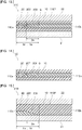
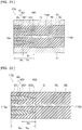
- Fig. 1 is a sectional view schematically showing a laminated glass in a laminated glass set in accordance with a first embodiment of the present invention.
- Fig. 2 is a sectional view schematically showing an interlayer film for use in obtaining the laminated glass shown in Fig. 1 .
- a laminated glass 31 shown in Fig. 1 includes a cut piece obtained by cutting an interlayer film 11 shown in Fig. 2 , as an interlayer film part 11P.
- the laminated glass 31 includes a first lamination glass member 21, a second lamination glass member 22, and the interlayer film part 11P.
- the interlayer film part 11P is arranged between the first lamination glass member 21 and the second lamination glass member 22.
- the first lamination glass member 21 is arranged on a first surface side of the interlayer film part 11P to be layered thereon.
- the second lamination glass member 22 is arranged on a second surface side opposite to the first surface of the interlayer film part 11P to be layered thereon.
- the interlayer film part 11P has one end 11a and the other end 11b at the opposite side of the one end 11a.
- the interlayer film part 11P includes a first resin layer 1 and a second resin layer 2 containing a coloring agent.
- the second resin layer 2 reaches the one end 11a of the interlayer film part 11P.
- the one end 11a part of the interlayer film part 11P is configured by the second resin layer 2 and the first resin layer 1.
- the second resin layer 2 forms a colored part.
- the first resin layer 1 is arranged on both surface sides of the second resin layer 2, the first resin layer 1 is arranged.
- the second resin layer 2 is embedded in the first resin layer 1.
- the first resin layer 1 is a surface layer of the interlayer film part 11P.
- the second resin layer 2 is an intermediate layer of the interlayer film part 11P.
- the second resin layer 2 has a gradation part 2X where visible light transmittance increases from the one end 11a side toward the other end 11b side of the interlayer film part 11P.
- the second resin layer 2 has a dark color part 2Y on the one end 11a side of the interlayer film part 11P.
- the second resin layer 2 reaches the one end 11a of the interlayer film part 11P at the dark color part 2Y.
- the gradation part 2X is a part where the thickness of the second resin layer 2 decreases from the one end 11a side toward the other end 11b side of the interlayer film part 11P.
- the dark color part 2Y is a part where the thickness of the second resin layer 2 is uniform.
- the colored part is configured by the gradation part 2X and the dark color part 2Y.
- the gradation part 2X forms a tip of the colored part on the other end 11b side of the interlayer film part 11P.
- Fig. 1 shows only one laminated glass 31.
- a plurality of cut pieces can be obtained.
- a plurality of laminated glasses 31, namely a laminated glass set can be obtained.
- the distance X and the distance Y are the same value in one laminated glass 31.
- Fig. 2 is a sectional view in the widthwise direction of the interlayer film 11.
- the right and left direction of Fig. 2 is the widthwise direction of the interlayer film 11.
- the fore-and-aft direction of Fig. 2 is the lengthwise direction of the interlayer film 11.
- the interlayer film 11 has one end 11a on one side in the widthwise direction, and the other end 11b on the other side in the widthwise direction.
- the interlayer film 11 includes the first resin layer 1 and the second resin layer 2 as with the interlayer film part 11P.
- the colored part has a gradation part 2X and a dark color part 2Y.
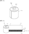
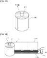
- Fig. 3 is a perspective view schematically showing a roll body prepared by winding the interlayer film shown in Fig. 2 .
- the interlayer film 11 may be wound to be formed into a roll body 51 of the interlayer film 11.
- the roll body 51 shown in Fig. 3 includes a winding core 61 and the interlayer film 11.
- the interlayer film 11 is wound around an outer periphery of the winding core 61.
- the interlayer film 11 is wound around the outer periphery of the winding core 61 from the other end side in the lengthwise direction of the interlayer film 11.
- Fig. 4 is a perspective view schematically showing a partially developed state of a roll body prepared by winding the interlayer film shown in Fig. 2 .
- Fig. 4 schematically shows the colored state. The darker the color tone, the lower the visible light transmittance.
- the distance X, the distance Y and the distance Z in the laminated glass 31 may correspond to distance X, distance Y and distance Z in Fig. 4 .
- Fig. 5 is a sectional view schematically showing a laminated glass in a laminated glass set in accordance with a second embodiment of the present invention.
- Fig. 6 is a sectional view schematically showing an interlayer film for use in obtaining the laminated glass shown in Fig. 5 .
- Fig. 5 is a sectional view of a laminated glass 31A.
- the right and left direction of Fig. 5 is the widthwise direction of the laminated glass 31A.
- the fore-and-aft direction of Fig. 5 is the lengthwise direction of the laminated glass 31A.
- the laminated glass 31A includes a cut piece obtained by cutting an interlayer film 11A shown in Fig. 6 , as an interlayer film part 11AP.
- the laminated glass 31A includes the first lamination glass member 21, the second lamination glass member 22, and the interlayer film part 11AP.
- the interlayer film part 11AP is arranged between the first lamination glass member 21 and the second lamination glass member 22.
- the first lamination glass member 21 is arranged on a first surface side of the interlayer film part 11AP to be layered thereon.
- the second lamination glass member 22 is arranged on a second surface side opposite to the first surface of the interlayer film part 11AP to be layered thereon.
- the interlayer film part 11AP has one end 11Aa and the other end 11Ab at the opposite side of the one end 11Aa.
- the interlayer film part 11AP includes a first resin layer 1A and a second resin layer 2A containing a coloring agent.
- the second resin layer 2A does not reach the one end 11Aa of the interlayer film part 11AP.
- the one end 11Aa part of the interlayer film part 11AP is configured only by the first resin layer 1A.
- the second resin layer 2A forms a colored part.
- the first resin layer 1A is arranged on both surface sides of the second resin layer 2A.
- the second resin layer 2A is embedded in the first resin layer 1A.
- the first resin layer 1A is a surface layer of the interlayer film part 11AP.
- the second resin layer 2A is an intermediate layer of the interlayer film part 11AP.
- the second resin layer 2A has a gradation part 2AX where visible light transmittance increases from the one end 11Aa side toward the other end 11Ab side of the interlayer film part 11AP.
- the second resin layer 2A has a dark color part 2AY on the one end 11Aa side of the interlayer film part 11AP.
- the gradation part 2AX is a part where the thickness of the second resin layer 2A decreases from the one end 11Aa side toward the other end 11Ab side of the interlayer film part 11AP.
- the dark color part 2AY is a part where the thickness of the second resin layer 2A is uniform.
- the colored part is configured by the gradation part 2AX and the dark color part 2AY.
- the gradation part 2AX forms a tip of the colored part on the other end 11Ab side of the interlayer film part 11AP.
- Fig. 5 shows only one laminated glass 31A.
- a plurality of cut pieces can be obtained.
- a plurality of laminated glasses 31A namely a laminated glass set can be obtained.
- Fig. 6 is a sectional view in the widthwise direction of the interlayer film 11A.
- the right and left direction of Fig. 6 is the widthwise direction of the interlayer film 11A.
- the fore-and-aft direction of Fig. 6 is the lengthwise direction of the interlayer film 11A.
- the interlayer film 11A shown in Fig. 6 has one end 11Aa on one side in the widthwise direction, and the other end 11Ab on the other side in the widthwise direction.
- the interlayer film 11A includes the first resin layer 1A and the second resin layer 2A as with the interlayer film part 11AP.
- the colored part has the gradation part 2AX and the dark color part 2AY.
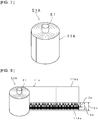
- Fig. 7 is a perspective view schematically showing a roll body prepared by winding the interlayer film shown in Fig. 6 .
- the interlayer film 11A may be wound to be formed into a roll body 51A of the interlayer film 11A.
- the roll body 51A shown in Fig. 7 includes the winding core 61 and the interlayer film 11A.
- the interlayer film 11A is wound around an outer periphery of the winding core 61.
- the interlayer film 11A is wound around the outer periphery of the winding core 61 from the other end side in the lengthwise direction of the interlayer film 11A.
- Fig. 8 is a perspective view schematically showing a partially developed state of a roll body prepared by winding the interlayer film shown in Fig. 6 .
- Fig. 8 schematically shows the colored state. The darker the color tone, the lower the visible light transmittance.
- the distance X, the distance Y and the distance Z in the laminated glass 31A may correspond to distance X, distance Y and distance Z in Fig. 8 .
- Fig. 9 is a sectional view schematically showing a laminated glass in a laminated glass set in accordance with a third embodiment of the present invention.
- Fig. 10 is a sectional view schematically showing an interlayer film for use in obtaining the laminated glass shown in Fig. 9 .
- a laminated glass 31B shown in Fig. 9 includes a cut piece obtained by cutting an interlayer film 11B shown in Fig. 10 , as an interlayer film part 11BP.
- the laminated glass 31B includes the first lamination glass member 21, the second lamination glass member 22, and the interlayer film part 11BP.
- the interlayer film part 11BP is arranged between the first lamination glass member 21 and the second lamination glass member 22.
- the first lamination glass member 21 is arranged on a first surface side of the interlayer film part 11BP to be layered thereon.
- the second lamination glass member 22 is arranged on a second surface side opposite to the first surface of the interlayer film part 11BP to be layered thereon.
- the interlayer film part 11BP has one end 11Ba and the other end 11Bb at the opposite side of the one end 11Ba.
- the interlayer film part 11BP includes a first resin layer 1B and a second resin layer 2B containing a coloring agent.
- the second resin layer 2B does not reach the one end 11Ba of the interlayer film part 11BP.
- the one end 11Ba part of the interlayer film part 11BP is configured only by the first resin layer 1B.
- the second resin layer 2B forms a colored part.
- the first resin layer 1B is arranged on both surface sides of the second resin layer 2B.
- the second resin layer 2B is embedded in the first resin layer 1B.
- the first resin layer 1B is a surface layer of the interlayer film part 11BP.
- the second resin layer 2B is an intermediate layer of the interlayer film part 11BP.
- the second resin layer 2B has a first gradation part 2BX where visible light transmittance increases from the one end 11Ba side toward the other end 11Bb side of the interlayer film part 11BP.
- the first gradation part 2BX forms a tip of the colored part on the other end 11Bb side of the interlayer film part 11BP.
- the second resin layer 2B has a second gradation part 2BZ where visible light transmittance increases from the other end 11Bb side toward the one end 11Ba side of the interlayer film part 11BP, on the one end 11Ba side of the interlayer film part 11BP.
- the first gradation part 2BX is a part where the thickness of the second resin layer 2B decreases from the one end 11Ba side toward the other end 11Bb side of the interlayer film part 11BP.
- the second gradation part 2BZ is a part where the thickness of the second resin layer 2B decreases from the other end 11Bb side toward the one end 11Ba side of the interlayer film part 11BP.
- Fig. 9 shows only one laminated glass 31B.
- a plurality of cut pieces can be obtained.
- a plurality of laminated glasses 31B namely a laminated glass set can be obtained.
- Fig. 10 is a sectional view in the widthwise direction of the interlayer film 11B.
- the right and left direction of Fig. 10 is the widthwise direction of the interlayer film 11B.
- the fore-and-aft direction of Fig. 10 is the lengthwise direction of the interlayer film 11B.
- the interlayer film 11B has one end 11Ba on one side in the widthwise direction, and the other end 11Bb on the other side in the widthwise direction.
- the interlayer film 11B includes the first resin layer 1B and the second resin layer 2B as with the interlayer film part 11BP.
- the second resin layer 2B has the first gradation part 2BX, and the second gradation part 2BZ.
- Fig. 11 is a perspective view schematically showing a roll body prepared by winding the interlayer film shown in Fig. 10 .
- the interlayer film 11B may be wound to be formed into a roll body 51B of the interlayer film 11B.
- the roll body 51B shown in Fig. 11 includes the winding core 61 and the interlayer film 11B.
- the interlayer film 11B is wound around an outer periphery of the winding core 61.
- the interlayer film 11B is wound around the outer periphery of the winding core 61 from the other end side in the lengthwise direction of the interlayer film 11B.
- Fig. 12 is a perspective view schematically showing a partially developed state of a roll body prepared by winding the interlayer film shown in Fig. 10 .
- Fig. 12 schematically shows the colored state. The darker the color tone, the lower the visible light transmittance.
- the distance X, the distance Y and the distance Z in the laminated glass 31B may correspond to distance X, distance Y and distance Z in Fig. 12 .
- the distance X and the distance Y are different values. It is to be noted that the width of the second gradation part 2BZ is not included in the distance Z because the second gradation part 2BZ is not a part where visible light transmittance increases from the one end 11Ba side toward the other end 11Bb side of the interlayer film part 11BP (first gradation part 2BX).
- Fig. 13 is a sectional view schematically showing a laminated glass in a laminated glass set in accordance with a fourth embodiment of the present invention.
- Fig. 14 is a sectional view schematically showing an interlayer film for use in obtaining the laminated glass shown in Fig. 13 .
- a coloring agent Q is schematically shown, and abundance of the coloring agent Q is schematically shown.
- the actual size of the coloring agent is significantly smaller than the size shown in Fig. 13 and Fig. 14 .
- illustration of a coloring agent is omitted.
- a laminated glass 31C shown in Fig. 13 includes a cut piece obtained by cutting an interlayer film 11C shown in Fig. 14 , as an interlayer film part 11CP.
- the laminated glass 31C includes the first lamination glass member 21, the second lamination glass member 22, and the interlayer film part 11CP.
- the interlayer film part 11CP is arranged between the first lamination glass member 21 and the second lamination glass member 22.
- the first lamination glass member 21 is arranged on a first surface side of the interlayer film part 11CP to be layered thereon.
- the second lamination glass member 22 is arranged on a second surface side opposite to the first surface of the interlayer film part 11CP to be layered thereon.
- the interlayer film part 11CP has one end 11Ca and the other end 11Cb at the opposite side of the one end 11Ca.
- the interlayer film part 11CP includes a first resin layer 1C and a second resin layer 2C containing a coloring agent Q.
- the second resin layer 2C reaches the one end 11Ca of the interlayer film part 11CP.
- the one end 11Ca part of the interlayer film part 11CP is configured by the second resin layer 2C and the first resin layer 1C.
- the part containing the coloring agent Q in the second resin layer 2C forms a colored part.
- the second resin layer 2C has a gradation part 2CX.
- the second resin layer 2C has a dark color part 2CY on the one end 11Ca side of the interlayer film part 11CP.
- the second resin layer 2C reaches the one end 11Ca of the interlayer film part 11CP at the dark color part 2CY.
- the gradation part 2CX is a part where the concentration of the coloring agent Q decreases from the one end 11Ca side toward the other end 11Cb side of the interlayer film part 11CP.
- the dark color part 2CY is a part where the concentration of the coloring agent Q is uniform.
- the colored part is configured by the gradation part 2CX and the dark color part 2CY.
- the gradation part 2CX forms a tip of the colored part on the other end 11Cb side of the interlayer film part 11CP.
- the one end 11Ca side of the interlayer film part 11CP is configured by three layers: the first resin layer 1C, the second resin layer 2C and the first resin layer 1C. On both surface sides of the second resin layer 2C, the first resin layer 1C is arranged. The second resin layer 2C is embedded in the first resin layer 1C. On the one end 11Ca side of the interlayer film part 11CP, the two first resin layers 1C are surface layers of the interlayer film part 11CP. On the one end 11Ca side of the interlayer film part 11CP, the one second resin layer 2C is an intermediate layer of the interlayer film part 11CP.
- the other end 11Cb side of the interlayer film part 11CP is configured by three layers: the first resin layer 1C, the second resin layer 2C, and the first resin layer 1C.
- the two first resin layers 1C are surface layers of the interlayer film part 11CP.
- the one first resin layer 1C is an intermediate layer of the interlayer film part 11CP.
- the second resin layer 2C which is an intermediate layer, and the first resin layer 1C which is a surface layer are continuous.
- the gradation part may be formed by the variation in concentration of the coloring agent.
- Fig. 13 shows only one laminated glass 31C.
- a plurality of cut pieces can be obtained.
- a plurality of laminated glasses 31C namely a laminated glass set can be obtained.
- Fig. 14 is a sectional view in the widthwise direction of the interlayer film 11C.
- the right and left direction of Fig. 14 is the widthwise direction of the interlayer film 11C.
- the fore-and-aft direction of Fig. 14 is the lengthwise direction of the interlayer film 11C.
- the interlayer film 11C has one end 11Ca on one side in the widthwise direction, and the other end 11Cb on the other side in the widthwise direction.
- the interlayer film 11C includes the first resin layer 1C and the second resin layer 2C as with the interlayer film part 11CP.
- the colored part has the gradation part 2CX and the dark color part 2CY.
- the interlayer film 11C may also be a roll body.
- Fig. 15 is a sectional view schematically showing a laminated glass in a laminated glass set in accordance with a fifth embodiment of the present invention.
- Fig. 16 is a sectional view schematically showing an interlayer film for use in obtaining the laminated glass shown in Fig. 15 .
- a laminated glass 31D shown in Fig. 15 includes a cut piece obtained by cutting an interlayer film 11D shown in Fig. 16 , as an interlayer film part 11DP.
- the laminated glass 31D includes the first lamination glass member 21, the second lamination glass member 22, and the interlayer film part 11DP.
- the interlayer film part 11DP is arranged between the first lamination glass member 21 and the second lamination glass member 22.
- the first lamination glass member 21 is arranged on a first surface side of the interlayer film part 11DP to be layered thereon.
- the second lamination glass member 22 is arranged on a second surface side opposite to the first surface of the interlayer film part 11DP to be layered thereon.
- the interlayer film part 11DP has one end 11Da and the other end 11Db at the opposite side of the one end 11Da.
- the interlayer film part 11DP includes a first resin layer 1D and a second resin layer 2D containing a coloring agent.
- the second resin layer 2D reaches the one end 11Da of the interlayer film part 11P.
- the one end 11Da part of the interlayer film part 11DP is configured by the second resin layer 2 and the first resin layer 1D.
- the second resin layer 2D forms a colored part.
- the first resin layer 1D is arranged on either surface side of the second resin layer 2D.
- the second resin layer 2D is not embedded in the first resin layer 1D.
- the first resin layer 1D is a surface layer of the interlayer film part 11DP.
- the second resin layer 2D is a surface layer of the interlayer film part 11DP.
- the second resin layer 2D has a gradation part 2DX where visible light transmittance increases from the one end 11Da side toward the other end 11Db side of the interlayer film part 11DP.
- the second resin layer 2D has a dark color part 2DY on the one end 11Da side of the interlayer film part 11DP.
- the second resin layer 2D reaches the one end 11Da of the interlayer film part 11DP at the dark color part 2DY.
- the gradation part 2DX is a part where the thickness of the second resin layer 2D decreases from the one end 11Da side toward the other end 11Db side of the interlayer film part 11DP.
- the dark color part 2DY is a part where the thickness of the second resin layer 2D is uniform.
- the colored part is configured by the gradation part 2DX and the dark color part 2DY.
- the gradation part 2DX forms a tip of the colored part on the other end 11Db side of the interlayer film part 11DP.
- the second resin layer need not be embedded in the first resin layer, and the second resin layer may be a surface layer.
- Fig. 15 shows only one laminated glass 31D.
- a plurality of cut pieces can be obtained.
- a plurality of laminated glasses 31D namely a laminated glass set can be obtained.
- Fig. 16 is a sectional view in the widthwise direction of the interlayer film 11D.
- the right and left direction of Fig. 16 is the widthwise direction of the interlayer film 11D.
- the fore-and-aft direction of Fig. 16 is the lengthwise direction of the interlayer film 11D.
- the interlayer film 11D has one end 11Da on one side in the widthwise direction, and the other end 11Db on the other side in the widthwise direction.
- the interlayer film 11D includes the first resin layer 1D and the second resin layer 2D as with the interlayer film part 11DP.
- the colored part has the gradation part 2DX and the dark color part 2DY.
- the interlayer film 11D may also be a roll body.
- Fig. 17 is a sectional view schematically showing a laminated glass in a laminated glass set in accordance with a sixth embodiment of the present invention.
- Fig. 18 is a sectional view schematically showing an interlayer film for use in obtaining the laminated glass shown in Fig. 17 .
- a laminated glass 31E shown in Fig. 17 includes a cut piece obtained by cutting the interlayer film 11E shown in Fig. 18 , as an interlayer film part 11EP.
- the laminated glass 31E includes the first lamination glass member 21, the second lamination glass member 22, and the interlayer film part 11EP.
- the interlayer film part 11EP is arranged between the first lamination glass member 21 and the second lamination glass member 22.
- the first lamination glass member 21 is arranged on a first surface side of the interlayer film part 11EP to be layered thereon.
- the second lamination glass member 22 is arranged on a second surface side opposite to the first surface of the interlayer film part 11EP to be layered thereon.
- the interlayer film part 11EP has one end 11Ea and the other end 11Eb at the opposite side of the one end 11Ea.
- the interlayer film part 11EP includes a first resin layer 1E, a second resin layer 2E containing a coloring agent, a third resin layer 3E, and a fourth resin layer 4E.
- the second resin layer 2E reaches the one end 11Ea of the interlayer film part 11EP.
- the one end 11Ea part of the interlayer film part 11EP is configured by the second resin layer 2E, the first resin layer 1E, the third resin layer 3E and the fourth resin layer 4E.
- the second resin layer 2E forms a colored part.
- the first resin layer 1E is arranged on both surface sides of the second resin layer 2E.
- the second resin layer 2E is embedded in the first resin layer 1E.
- the first resin layer 1E is a surface layer of the interlayer film part 11EP.
- the second resin layer 2E is an intermediate layer of the interlayer film part 11EP.
- the third resin layer 3E is arranged on a surface side opposite to the second resin layer 2E of the first resin layer 1E to be layered thereon.
- the fourth resin layer 4E is arranged on a surface side opposite to the first resin layer 1E of the third resin layer 3E to be layered thereon.
- the third resin layer 3E is an intermediate layer of the interlayer film part 11EP.
- the third resin layer 3E is a sound insulating layer.
- the fourth resin layer 4E is a surface layer of the interlayer film part 11EP.
- the second resin layer 2E has a gradation part 2EX where visible light transmittance increases from the one end 11Ea side toward the other end 11Eb side of the interlayer film part 11EP.
- the second resin layer 2E has a dark color part 2EY on the one end 11Ea side of the interlayer film part 11EP.
- the second resin layer 2E reaches the one end 11Ea of the interlayer film part 11EP at the dark color part 2EY.
- the gradation part 2EX is a part where the thickness of the second resin layer 2E decreases from the one end 11Ea side toward the other end 11Eb side of the interlayer film part 11EP.
- the dark color part 2EY is a part where the thickness of the second resin layer 2E is uniform.
- the colored part is configured by the gradation part 2EX and the dark color part 2EY.
- the gradation part 2EX forms a tip of the colored part on the other end 11Eb side of the interlayer film part 11EP.
- Fig. 17 shows only one laminated glass 31E.
- a plurality of cut pieces can be obtained.
- a plurality of laminated glasses 31E namely a laminated glass set can be obtained.
- Fig. 18 is a sectional view in the widthwise direction of the interlayer film 11E.
- the right and left direction of Fig. 18 is the widthwise direction of the interlayer film 11E.
- the fore-and-aft direction of Fig. 18 is the lengthwise direction of the interlayer film 11E.
- the interlayer film 11E has one end 11Ea on one side in the widthwise direction, and the other end 11Eb on the other side in the widthwise direction.
- the interlayer film 11E has the first resin layer 1E, the second resin layer 2E, the third resin layer 3E, and the fourth resin layer 4E as with the interlayer film part 11EP.
- the colored part has the gradation part 2EX and the dark color part 2EY.
- the interlayer film 11E may also be a roll body.
- Fig. 19 is a sectional view schematically showing a laminated glass in a laminated glass set in accordance with a seventh embodiment of the present invention.
- Fig. 20 is a sectional view schematically showing an interlayer film for use in obtaining the laminated glass shown in Fig. 19 .
- a laminated glass 31F shown in Fig. 19 includes a cut piece obtained by cutting the interlayer film 11F shown in Fig. 20 , as an interlayer film part 11FP.
- the laminated glass 31F includes the first lamination glass member 21, the second lamination glass member 22, and the interlayer film part 11FP.
- the interlayer film part 11FP is arranged between the first lamination glass member 21 and the second lamination glass member 22.
- the first lamination glass member 21 is arranged on a first surface side of the interlayer film part 11FP to be layered thereon.
- the second lamination glass member 22 is arranged on a second surface side opposite to the first surface of the interlayer film part 11FP to be layered thereon.
- the interlayer film part 11FP has one end 11Fa and the other end 11Fb at the opposite side of the one end 11Fa.
- the interlayer film part 11FP includes a first resin layer 1F, a second resin layer 2F containing a coloring agent, a functional film 5F, and a third resin layer 3F.
- the second resin layer 2F reaches the one end 11Fa of the interlayer film part 11FP.
- the one end 11Fa part of the interlayer film part 11FP is configured by the second resin layer 2F, the first resin layer 1F, the functional film 5F and the third resin layer 3F.
- the second resin layer 2F forms a colored part.
- the first resin layer 1F is arranged on both surface sides of the second resin layer 2F.
- the second resin layer 2F is embedded in the first resin layer 1F.
- the first resin layer 1F is a surface layer of the interlayer film part 11FP.
- the second resin layer 2F is an intermediate layer of the interlayer film part 11FP.
- the functional film 5F is arranged on a surface side opposite to the second resin layer 2F of the first resin layer 1F to be layered thereon.
- the third resin layer 3F is arranged on a surface side opposite to the first resin layer 1F of the functional film 5F to be layered thereon.
- the functional film 5F is an intermediate layer of the interlayer film part 11FP.
- the third resin layer 3F is a surface layer of the interlayer film part 11FP.
- the functional film 5F is an infrared ray reflective film.
- the second resin layer 2F has a gradation part 2FX where visible light transmittance increases from the one end 11Fa side toward the other end 11Fb side of the interlayer film part 11FP.
- the second resin layer 2F has a dark color part 2FY on the one end 11Fa side of the interlayer film part 11FP.
- the second resin layer 2F reaches the one end 11Fa of the interlayer film part 11FP at the dark color part 2FY.
- the gradation part 2FX is a part where the thickness of the second resin layer 2F decreases from the one end 11Fa side toward the other end 11Fb side of the interlayer film part 11FP.
- the dark color part 2FY is a part where the thickness of the second resin layer 2F is uniform.
- the colored part is configured by the gradation part 2FX and the dark color part 2FY.
- the gradation part 2FX forms a tip of the colored part on the other end 11Fb side of the interlayer film part 11FP.
- Fig. 19 shows only one laminated glass 31F.
- a plurality of cut pieces can be obtained.
- a plurality of laminated glasses 31F namely a laminated glass set can be obtained.
- Fig. 20 is a sectional view in the widthwise direction of an interlayer film 11F.
- the right and left direction of Fig. 20 is the widthwise direction of the interlayer film 11F.
- the fore-and-aft direction of Fig. 20 is the lengthwise direction of the interlayer film 11F.
- the interlayer film 11F has one end 11Fa on one side in the widthwise direction, and the other end 11Fb on the other side in the widthwise direction.
- the interlayer film 11F has the first resin layer 1F, the second resin layer 2F, the functional film 5F, and the third resin layer 3F, as with the interlayer film part 11FP.
- the colored part has the gradation part 2FX and the dark color part 2FY.
- the interlayer film 11F may also be a roll body.
- Fig. 21 is a sectional view schematically showing a laminated glass in a laminated glass set in accordance with an eighth embodiment of the present invention.
- Fig. 22 is a sectional view schematically showing an interlayer film for use in obtaining the laminated glass shown in Fig. 21 .
- a laminated glass 31G shown in Fig. 21 includes a cut piece obtained by cutting the interlayer film 11G shown in Fig. 22 , as an interlayer film part 11GP.
- the laminated glass 31G includes the first lamination glass member 21, the second lamination glass member 22, and the interlayer film part 11GP.
- the interlayer film part 11GP is arranged between the first lamination glass member 21 and the second lamination glass member 22.
- the first lamination glass member 21 is arranged on a first surface side of the interlayer film part 11GP to be layered thereon.
- the second lamination glass member 22 is arranged on a second surface side opposite to the first surface of the interlayer film part 11GP to be layered thereon.
- the interlayer film part 11GP has one end 11Ga and the other end 11Gb at the opposite side of the one end 11Ga.
- the interlayer film part 11GP includes a first resin layer 1G, a second resin layer 2G containing a coloring agent, a functional film 5G, a third resin layer 3G, and a fourth resin layer 4G containing a coloring agent.
- the second resin layer 2G and the fourth resin layer 4G reach one end 11Ga of the interlayer film part 11GP.
- the one end 11Ga part of the interlayer film part 11GP is configured by the second resin layer 2G, the first resin layer 1G, the functional film 5G, the fourth resin layer 4G and the third resin layer 3G.
- the second resin layer 2G forms a colored part.
- the fourth resin layer 4G forms a colored part.
- the first resin layer 1G is arranged on both surface sides of the second resin layer 2G.
- the second resin layer 2G is embedded in the first resin layer 1G.
- the first resin layer 1G is a surface layer of the interlayer film part 11GP.
- the second resin layer 2G is an intermediate layer of the interlayer film part 11GP.
- the third resin layer 3G is arranged on both surface sides of the fourth resin layer 4G.
- the fourth resin layer 4G is embedded in the third resin layer 3G.
- the third resin layer 3G is a surface layer of the interlayer film part 11GP.
- the fourth resin layer 4G is an intermediate layer of the interlayer film part 11GP.
- the functional film 5G is arranged on a surface side opposite to the second resin layer 2G of the first resin layer 1G to be layered thereon.
- the functional film 5G is arranged on a surface side opposite to the fourth resin layer 4G of the third resin layer 3G to be layered thereon.
- the functional film 5G is an infrared ray reflective film.
- the second resin layer 2G has a gradation part 2GX where visible light transmittance increases from the one end 11Ga side toward the other end 11Gb side of the interlayer film part 11GP.
- the second resin layer 2G has a dark color part 2GY on the one end 11Ga side of the interlayer film part 11GP.
- the second resin layer 2G reaches the one end 11Ga of the interlayer film part 11GP at the dark color part 2GY.
- the gradation part 2GX is a part where the thickness of the second resin layer 2G decreases from the one end 11Ga side toward the other end 11Gb side of the interlayer film part 11GP.
- the dark color part 2GY is a part where the thickness of the second resin layer 2G is uniform.
- the fourth resin layer 4G has a gradation part 4GX where visible light transmittance increases from the one end 11Ga side toward the other end 11Gb side of the interlayer film part 11GP.
- the fourth resin layer 4G has the dark color part 4GY on the one end 11Ga side of the interlayer film part 11GP.
- the fourth resin layer 4G reaches the one end 11Ga of the interlayer film part 11GP at the dark color part 4GY.
- the gradation part 4GX is a part where the thickness of the fourth resin layer 4G decreases from the one end 11Ga side toward the other end 11Gb side of the interlayer film part 11GP.
- the dark color part 4GY is a part where the thickness of the fourth resin layer 4G is uniform.
- the colored part is configured by the gradation part 2GX and the dark color part 2GY.
- the gradation part 2GX forms a tip of the colored part on the other end 11Gb side of the interlayer film part 11GP.
- the colored part is configured by the gradation part 4GX and the dark color part 4GY.
- the gradation part 4GX forms a tip of the colored part on the other end 11Gb side of the interlayer film part 11GP.
- Fig. 21 shows only one laminated glass 31G.
- a plurality of cut pieces can be obtained.
- a plurality of laminated glasses 31G namely a laminated glass set can be obtained.
- Fig. 22 is a sectional view in the widthwise direction of an interlayer film 11G.
- the right and left direction of Fig. 22 is the widthwise direction of the interlayer film 11G.
- the fore-and-aft direction of Fig. 22 is the lengthwise direction of the interlayer film 11G.
- the interlayer film 11G has one end 11Ga on one side in the widthwise direction, and the other end 11Gb on the other side in the widthwise direction.
- the interlayer film part 11GP has the first resin layer 1G, the second resin layer 2G containing a coloring agent, the functional film 5G, the third resin layer 3G, and the fourth resin layer 4G containing a coloring agent as with the interlayer film part 11GP.
- the colored part has the gradation parts 2GX, 4GX and the dark color parts 2GY, 4GY.
- the interlayer film 11G may also be a roll body.
- Fig. 23 is a front view showing a laminated glass set including a plurality of laminated glasses shown in Fig. 1 .
- Fig. 23 schematically shows the colored state. The darker the color tone, the lower the visible light transmittance.
- the laminated glass 31 is used among the laminated glasses 31, 31A, 31B, 31C, 31D, 31E, 31F, 31G as described above.
- the laminated glass set 71 includes a plurality of laminated glasses 31.
- a plurality of laminated glasses 31 are arranged.
- the plurality of laminated glasses 31 are handled as a set article.
- the interlayer film part 11P (the symbol is not shown) constituting the plurality of laminated glasses 31 in the laminated glass set 71 is obtained from one interlayer film 11.
- Fig. 24 is a front view showing the first example of a laminated glass structure using the laminated glass set shown in Fig. 23 .
- Fig. 24 schematically shows the colored state. The darker the color tone, the lower the visible light transmittance.
- the laminated glass 31 is used among the laminated glasses 31, 31A, 31B, 31C, 31D, 31E, 31F, 31G as described above.
- the laminated glass set 71 is used in the laminated glass structure 81.
- the laminated glass structure 81 includes the laminated glass set 71 and a connecting member 91.
- the connecting member 91 connects the laminated glasses 31 arranged in line.
- the connecting member 91 is a connecting member, and is a hinge.
- the hinge connects two laminated glasses 31. Two laminated glasses 31 are connected by one hinge.
- the laminated glass structure 81 can be bent forward or backward in Fig. 24 .
- the laminated glass structure 81 can be folded at the connecting member 91 part.
- Fig. 25 is a front view showing the second example of a laminated glass structure using the laminated glass set shown in Fig. 23 .
- Fig. 25 schematically shows the colored state.
- the laminated glass 31 is used among the laminated glasses 31, 31A, 31B, 31C, 31D, 31E, 31F, 31G as described above.
- the laminated glass set 71 is used in the laminated glass structure 82.
- the laminated glass structure 82 includes the laminated glass set 71 and a connecting member 92.
- the connecting member 92 connects the laminated glasses 31 arranged in line.
- the connecting member 92 is a connecting member, and is a frame member.
- the connecting member 92 surrounds the outer periphery of the laminated glass 31.
- the laminated glass 31 is attached to an opening of the connecting member 92.
- Fig. 26 is a front view showing a laminated glass structure prepared with a conventional laminated glass set.
- Fig. 26 schematically shows the colored state.
- a conventional interlayer film 102 is used in a laminated glass structure 101.
- the laminated glass structure prepared with a conventional laminated glass set has a problem that the variation in the position of the colored part, or the position of a tip of the colored part (tip of the gradation part) (broken line part in Fig. 26 ) is large.
- the laminated glass structures 81, 82 can reduce the variation in the position of the colored part and the position of a tip of the colored part (tip of the gradation part) (broken line part in Figs. 24, 25 ) because the aforementioned laminated glass 31 is used.
- first and second lamination glass members examples include a glass plate, a PET (polyethylene terephthalate) film, and the like.
- laminated glass laminated glass in which an interlayer film (interlayer film part) is sandwiched between a glass plate and a PET film or the like, as well as laminated glass in which an interlayer film (interlayer film part) is sandwiched between two glass plates, is included.
- the laminated glass is a laminate provided with a glass plate, and it is preferred that at least one glass plate be used. It is preferred that each of the first and second lamination glass members be a glass plate or a PET (polyethylene terephthalate) film and the laminated glass include at least one glass plate as the first and second lamination glass members. It is especially preferred that both of the first and second lamination glass members be glass plates.
- the glass plate examples include a sheet of inorganic glass and a sheet of organic glass.
- the inorganic glass examples include float plate glass, heat ray-absorbing plate glass, heat ray-reflecting plate glass, polished plate glass, figured plate glass, net plate glass, wired plate glass, green glass, and the like.
- the organic glass is synthetic resin glass substituted for inorganic glass.
- the organic glass examples include a polycarbonate plate, a poly(meth)acrylic resin plate, and the like.
- the poly(meth)acrylic resin plate examples include a polymethyl (meth)acrylate plate, and the like.
- the thickness is preferably 1 mm or more and preferably 5 mm or less.
- the thickness of the glass plate is preferably 1 mm or more and is preferably 5 mm or less.
- the thickness of the PET film is preferably 0.03 mm or more and is preferably 0.5 mm or less.
- the thickness of the first and second lamination glass members means an average thickness.
- the thickness of the interlayer film is not particularly limited. From the viewpoint of the practical aspect and the viewpoint of sufficiently enhancing the penetration resistance and the flexural rigidity of laminated glass, the thickness of the interlayer film is preferably 0.1 mm or more, more preferably 0.25 mm or more, and is preferably 3 mm or less, more preferably 1.5 mm or less. When the thickness of the interlayer film is the above lower limit or more, the penetration resistance and the flexural rigidity of laminated glass are further enhanced. When the thickness of the interlayer film is the above upper limit or less, the transparency of the interlayer film is further improved.
- the thickness of the interlayer film means an average thickness.
- the interlayer film contain a resin. It is preferred that the first resin layer contain a resin. It is preferred that the second resin layer contain a resin. It is preferred that the third resin layer contain a resin. It is preferred that the fourth resin layer contain a resin.
- the resin include thermosetting resins and thermoplastic resins, and the like. One kind of the resin may be used alone, and two or more kinds thereof may be used in combination.
- thermoplastic resin examples include a polyvinyl acetal resin, a polyester resin, an ethylene-vinyl acetate copolymer resin, an ethylene-acrylic acid copolymer resin, a polyurethane resin, a polyvinyl alcohol resin, and the like.
- Thermoplastic resins other than these may be used.
- the interlayer film contain a plasticizer. It is preferred that the first resin layer contain a plasticizer. It is preferred that the second resin layer contain a plasticizer. It is preferred that the third resin layer contain a plasticizer. It is preferred that the fourth resin layer contain a plasticizer.
- the thermoplastic resin contained in the interlayer film is a polyvinyl acetal resin, it is especially preferred that the interlayer film (the respective layers) contain a plasticizer.
- One kind of the plasticizer may be used alone and two or more kinds thereof may be used in combination.
- plasticizer examples include organic ester plasticizers such as a monobasic organic acid ester and a polybasic organic acid ester, organic phosphate plasticizers such as an organic phosphate plasticizer and an organic phosphite plasticizer, and the like.
- organic ester plasticizers are preferred. It is preferred that the plasticizer be a liquid plasticizer.
- Examples of the monobasic organic acid ester include a glycol ester obtained by the reaction of a glycol with a monobasic organic acid, and the like.
- Examples of the glycol include triethylene glycol, tetraethylene glycol, tripropylene glycol, and the like.
- Examples of the monobasic organic acid include butyric acid, isobutyric acid, caproic acid, 2-ethylbutyric acid, heptanoic acid, n-octylic acid, 2-ethylhexanoic acid, n-nonylic acid, decylic acid, benzoic acid and the like.
- polybasic organic acid ester examples include an ester compound of a polybasic organic acid and an alcohol having a linear or branched structure of 4 to 8 carbon atoms.
- polybasic organic acid examples include adipic acid, sebacic acid, azelaic acid, and the like.
- organic ester plasticizer examples include triethylene glycol di-2-ethylpropanoate, triethylene glycol di-2-ethylbutyrate, triethylene glycol di-2-ethylhexanoate, triethylene glycol dicaprylate, triethylene glycol di-n-octanoate, triethylene glycol di-n-heptanoate, tetraethylene glycol di-n-heptanoate, dibutyl sebacate, dioctyl azelate, dibutyl carbitol adipate, ethylene glycol di-2-ethylbutyrate, 1,3-propylene glycol di-2-ethylbutyrate, 1,4-butylene glycol di-2-ethylbutyrate, diethylene glycol di-2-ethylbutyrate, diethylene glycol di-2-ethylhexanoate, dipropylene glycol di-2-ethylbutyrate, triethylene glycol di-2-ethy
- organic phosphate plasticizer examples include tributoxyethyl phosphate, isodecyl phenyl phosphate, triisopropyl phosphate, and the like.
- the plasticizer be a diester plasticizer represented by the following formula (1).
- R1 and R2 each represent an organic group with 5 to 10 carbon atoms
- R3 represents an ethylene group, an isopropylene group, or an n-propylene group
- p represents an integer of 3 to 10. It is preferred that R1 and R2 in the foregoing formula (1) each be an organic group with 6 to 10 carbon atoms.
- the plasticizer include triethylene glycol di-2-ethylhexanoate (3GO), triethylene glycol di-2-ethylbutyrate (3GH) or triethylene glycol di-2-ethylpropanoate. It is more preferred that the plasticizer include triethylene glycol di-2-ethylhexanoate (3GO) or triethylene glycol di-2-ethylbutyrate (3GH), and it is further preferred that the plasticizer include triethylene glycol di-2-ethylhexanoate.
- a content of the plasticizer relative to 100 parts by mass of the resin is referred to as content (0).
- the content (0) is preferably 25 parts by mass or more, more preferably 30 parts by mass or more, and is preferably 100 parts by mass or less, more preferably 60 parts by mass or less, further preferably 50 parts by mass or less.
- the content (0) is the above lower limit or more, the penetration resistance of laminated glass is further enhanced.
- the transparency of the interlayer film is further enhanced.
- the interlayer film contain a coloring agent. It is preferred that the interlayer film part contain a coloring agent. It is preferred that the second resin layer contain a coloring agent.
- Each of the first resin layer, the third resin layer and the fourth resin layer may contain a coloring agent. It is preferred that at least one of the first resin layer and the second resin layer contain a coloring agent. Both the first resin layer and the second resin layer may contain a coloring agent. Examples of the coloring agent include inorganic particles, a dye, a pigment and the like.
- the inorganic particles include carbon black particles, carbon nanotube particles, graphene particles, iron oxide particles, zinc oxide particles, calcium carbonate particles, alumina particles, kaolin clay particles, calcium silicate particles, magnesium oxide particles, magnesium hydroxide particles, aluminum hydroxide particles, magnesium carbonate particles, talc particles, feldspar powder particles, mica particles, barite particles, barium carbonate particles, titanium oxide particles, silica particles, and glass beads, and the like.
- One kind of the inorganic particles may be used alone, and two or more kinds thereof may be used in combination.
- the inorganic particles include carbon black particles, carbon nanotube particles, graphene particles, calcium carbonate particles, titanium oxide particles or silica particles, and it is more preferred that the inorganic particles include calcium carbonate particles.
- the average particle diameter of the inorganic particles is preferably 0.01 ⁇ m or more, more preferably 0.5 ⁇ m or more, and is preferably 100 ⁇ m or less, more preferably 50 ⁇ m or less, further preferably 10 ⁇ m or less.
- the average particle diameter refers to the weight average particle diameter.
- the average particle diameter can be measured by a dynamic light scattering method with a light scattering measuring device and a laser as a light source. Examples of the light scattering measuring device include "DLS-6000AL" available from OTSUKA ELECTRONICS Co., LTD., and the like.
- the dye examples include a pyrene-based dye, an aminoketone-based dye, an anthraquinone-based dye, and an azo-based dye, and the like.
- One kind of the dye may be used alone, and two or more kinds thereof may be used in combination.
- Examples of the pyrene-based dye include Solvent Green 5 ( CAS79869-59-3 ) and Solvent Green 7 ( CAS6358-69-6 ), and the like.
- aminoketone-based dye examples include Solvent Yellow 98 ( CAS12671-74-8 ), Solvent Yellow 85 ( CAS12271-01-1 ) and Solvent Red 179 ( CAS8910-94-5 ), and Solvent Red 135 ( CAS71902-17-5 ), and the like.
- anthraquinone-based dye examples include Solvent Yellow 163 ( CAS13676091-0 ), Solvent Red 207 ( CAS15958-69-6 ), Disperse Red 92 ( CAS12236-11-2 ), Solvent Violet 13 ( CAS81-48-1 ), Disperse Violet 31 ( CAS6408-72-6 ), Solvent Blue 97 ( CAS61969-44-6 ), Solvent Blue 45 ( CAS37229-23-5 ), Solvent Blue 104 ( CAS116-75-6 ) and Disperse Blue 214 ( CAS104491-84-1 ), and the like.
- azo-based dye examples include Solvent Yellow30 ( CAS3321-10-4 ), Solvent Red 164 ( CAS70956-30-8 ), and Disperse Blue 146 ( CAS88650-91-3 ), and the like.
- the pigment may be an organic pigment and may be an inorganic pigment.
- the organic pigment may be an organic pigment having a metal atom, and may be an organic pigment not having a metal atom.
- One kind of the pigment may be used alone, and two or more kinds thereof may be used in combination.
- organic pigment examples include a phthalocyanine compound, a quinacridone compound, an azo compound, a pentaphene compound, a perylene compound, an indole compound and a dioxazine compound, and the like.
- the first resin layer contains a coloring agent
- the first resin layer contain carbon black particles, carbon nanotube particles, graphene particles, calcium carbonate particles, titanium oxide particles, silica particles or a phthalocyanine compound, and it is especially preferred that the first resin layer contain calcium carbonate particles.
- the second resin layer contain carbon black particles, carbon nanotube particles, graphene particles, calcium carbonate particles, titanium oxide particles, silica particles or a phthalocyanine compound, and it is especially preferred that the second resin layer contain calcium carbonate particles.
- Each of the interlayer film, the light color part, and the colored part may contain additives such as heat shielding particles, a light shielding agent, a coloring agent, a UV absorber, an oxidation inhibitor, an adhesive force adjusting agent, a light stabilizer, a flame retarder, an antistatic agent, a moisture-proof agent, a heat rays reflector and a heat rays absorber, and the like, as necessary.
- additives such as heat shielding particles, a light shielding agent, a coloring agent, a UV absorber, an oxidation inhibitor, an adhesive force adjusting agent, a light stabilizer, a flame retarder, an antistatic agent, a moisture-proof agent, a heat rays reflector and a heat rays absorber, and the like, as necessary.
- One kind of the additives may be used alone and two or more kinds thereof may be used in combination.
- the first resin layer may contain the heat shielding particles.
- the second resin layer may contain the heat shielding particles.
- the third resin layer may contain the heat shielding particles.
- the fourth resin layer may contain the heat shielding particles.
- the energy amount of an infrared ray with a wavelength of 780 nm or longer which is longer than that of visible light is small as compared with an ultraviolet ray.
- the thermal action of infrared rays is large, and when infrared rays are absorbed into a substance, heat is released from the substance. Accordingly, infrared rays are generally called heat rays.
- the heat shielding particle means a particle capable of absorbing infrared rays. Since the interlayer film contains heat shielding particles, it is possible to improve the heat shielding property and the appearance designability of the laminated glass.
- the heat shielding particles include metal oxide particles such as aluminum-doped tin oxide particles, indium-doped tin oxide particles, antimony-doped tin oxide particles (ATO particles), gallium-doped zinc oxide particles (GZO particles), indium-doped zinc oxide particles (IZO particles), aluminum-doped zinc oxide particles (AZO particles), niobium-doped titanium oxide particles, sodium-doped tungsten oxide particles, cesium-doped tungsten oxide particles, thallium-doped tungsten oxide particles, rubidium-doped tungsten oxide particles, tin-doped indium oxide particles (ITO particles), tin-doped zinc oxide particles and silicon-doped zinc oxide particles, lanthanum hexaboride (LaB 6 ) particles, and the like. Heat shielding particles other than these may be used. One kind of the heat shielding particles may be used alone, and two or more kinds thereof may be used in combination.
- ATO particles
- the average particle diameter of the heat shielding particles is preferably 10 nm or more, more preferably 20 nm or more, and is preferably 100 nm or less, more preferably 80 nm or less, further preferably 50 nm or less.
- the average particle diameter is the above lower limit or more, it is possible to sufficiently enhance the heat ray shielding property.
- the average particle diameter is the above upper limit or less, the dispersibility of heat shielding particles is enhanced.
- the “average particle diameter” refers to the volume average particle diameter.
- the average particle diameter can be measured using a particle size distribution measuring apparatus ("UPA-EX150” available from NIKKISO CO., LTD.), or the like.
- the interlayer film part of the laminated glass set according to the present invention may include other functional film for the purpose of realizing other function.
- the functional film include an infrared reflective film, a colored film, and a film with design printing, and the like.
- the interlayer film part may include an infrared reflective film.
- the interlayer film part may include a colored film, or may include a film with design printing.
- the first resin layer and the second resin layer be arranged on a first surface side of the functional film, the third resin layer be arranged on a second surface side opposite to the first surface of the functional film, and the second resin layer be arranged between the first resin layers.
- the layer arranged on the first surface side of the functional film may be a single layer or may be multi-layered.
- the layer arranged on the second surface side of the functional film may be a single layer or may be multi-layered.
- the interlayer film including a functional film may include the first resin layer, the second resin layer and the third resin layer, or may include the first resin layer, the second resin layer, the third resin layer and the fourth resin layer on the first surface side of the functional film. Also, the interlayer film including a functional film may include the third resin layer and the fourth resin layer on the second surface side of the functional film.
- the infrared reflective film examples include a resin film with metal foil, a multilayer laminate film in which a metal layer and a dielectric layer are formed on a resin film, a multilayer resin film, and a liquid crystal film, and the like. These films have the property of reflecting infrared rays.
- the resin film with metal foil includes a resin film, and a metal foil layered on the outer surface of the resin film.
- the material of the resin film include a polyethylene terephthalate resin, a polyethylene naphthalate resin, a polyvinyl acetal resin, an ethylene-vinyl acetate copolymer resin, an ethylene-acrylic acid copolymer resin, a polyurethane resin, a polyvinyl alcohol resin, a polyolefin resin, a polyvinyl chloride resin, and a polyimide resin.
- the material of the metal foil include aluminum, copper, silver, gold, palladium, and alloys containing these metals.
- the multilayer laminate film in which a metal layer and a dielectric layer are formed on a resin film is a multilayer laminate film in which any number of layers of the metal layer and the dielectric layer are alternately layered on the resin film.
- a metal layer and a dielectric layer are formed on a resin layer, it is preferred that all of the metal layers and the dielectric layers be layered alternately, however, there may be a structural part in which a metal layer and a dielectric layer are not layered alternately as exemplified by metal layer/dielectric layer/metal layer/dielectric layer/metal layer/metal layer/dielectric layer/metal layer.
- Examples of the material of the resin film in the multilayer laminate film include polyethylene, polypropylene, polylactic acid, poly(4-methylpentene-1), polyvinylidene fluoride, cyclic polyolefin, polymethyl methacrylate, polyvinyl chloride, polyvinyl alcohol, polyamide such as nylon 6, 11, 12, 66 and the like, polystyrene, polycarbonate, polyethylene terephthalate, polyethylene naphthalate, polyester, polyphenylene sulfide, and polyether imide.
- the material of the metal layer in the multilayer laminate film those exemplified as the material of the metal foil in the resin film with metal foil can be exemplified.
- a coating layer of metal or a mixed oxide of metal can be given to the both faces or either face of the metal layer.
- the material of the coating layer include ZnO, Al 2 O 3 , Ga 2 O 3 , InO 3 , MgO, Ti, NiCr and Cu.
- examples of the dielectric layer in the multilayer laminate film include indium oxide.
- the multilayer resin film is a laminate film in which a plurality of resin films are layered.
- the material of the multilayer resin film those exemplified as the material of the resin film in the multilayer laminate film can be exemplified.
- the number of layered resin films in the multilayer resin film is 2 or more, and may be 3 or more, and may be 5 or more.
- the number of layered resin films in the multilayer resin film may be 1000 or less, and may be 100 or less, and may be 50 or less.
- the multilayer resin film may be a multilayer resin film in which any number of layers of two or more kinds of thermoplastic resin films having different optical properties (refractive index) are layered alternately or randomly. Such a multilayer resin film is so configured that a desired infrared reflecting property is obtained.
- liquid crystal film a film in which any number of layers of cholesteric liquid crystal layers that reflect the light of any wavelength are layered can be recited. Such a liquid crystal film is so configured that desired infrared reflecting property is obtained.
- the infrared reflective film may contain infrared reflective particles.
- the infrared reflective particles are particles having the infrared reflecting property, and for example, tabular particles having a thickness of 1 nm or more and 1000 ⁇ m or less can be recited.
- an infrared reflective film having infrared reflecting property is obtained by adjusting the thickness, the surface area and the arrangement state of the silver nano tabular particles.
- Polyvinyl butyral resin 1 (polymerization degree: 1700, amount of acetal group: 69 mol%, amount of hydroxyl group: 30 mol%, amount of acetyl group: 1 mol%) (hereinafter, also referred to as PVB1)
- Polyvinyl butyral resin 2 (polymerization degree: 1700, amount of acetal group: 70 mol%, amount of hydroxyl group: 18 mol%, amount of acetyl group: 12 mol%)
- Polyvinyl butyral resin 3 (polymerization degree: 2300, amount of acetal group: 70 mol%, amount of hydroxyl group: 18 mol%, amount of acetyl group: 12 mol%)
- Polyvinyl butyral resin 4 (polymerization degree: 3300, amount of acetal group: 70 mol%, amount of hydroxyl group: 18 mol%, amount of acetyl group: 18 mol%, amount of acetyl group:
- Triethylene glycol-2-ethylhexanoate (hereinafter, sometimes described as 3GO)
- Calcium carbonate calcium carbonate particles ("SUPER 4S" available from MARUO CALCIUM CO., LTD.
- Blue pigment copper phthalocyanine pigment (Pigment Blue 15)
- Black pigment carbon black (Pigment Black 7)
- ITO tin-doped indium oxide particles (average particle diameter: 50 nm)
- CWO cesium-doped tungsten oxide particles (average particle diameter: 50 nm)
- 3M90S multilayer resin film, "Multilayer Nano 90S” available from Sumitomo 3M Limited
- XIR resin film with metal foil, "XIR-75” available from Southwall Technologies
- Example 1 a plurality of laminated glasses as shown in Fig. 1 were prepared.
- the resin composition A1 for forming a first resin layer and the resin composition B1 for forming a second resin layer were co-extruded with a co-extruder, and then wound to obtain a roll body of the interlayer film having a length of 40 m.
- the revolving speed of the gear pump was PID controlled on the basis of the discharge pressure and the inlet pressure measured every 0.1 seconds, and parameters of the control function were optimized, and thus variation in the inlet pressure in a long period of 180 seconds was suppressed.
- difference between the maximum value and the minimum value of the inlet pressure (inlet pressure variation) in 180 seconds was set at 30 ⁇ 10 5 Pa in the gear pump 1 for extruding the resin composition A1 for forming a first resin layer.
- difference between the maximum value and the minimum value of the inlet pressure (inlet pressure variation) in 180 seconds was set at 30 ⁇ 10 5 Pa in the gear pump 1 for extruding the resin composition B1 for forming a second resin layer.
- the linear velocity at the time of extrusion was 10 m/min.
- the width of the interlayer film was 1800 mm.
- the interlayer film was cut out to obtain an interlayer film part having a short-side dimension (lengthwise direction of the interlayer film) of 1.5 m, and a long-side dimension and a thickness that are equivalent to the width and the thickness of the interlayer film.
- the interlayer film was cut out with a cutter knife or scissors. Since the divisional positions were set at 20 positions in the lengthwise direction in the obtained interlayer film, 20 interlayer film parts were obtained. These 20 interlayer film parts were named interlayer film part (1), interlayer film part (2), interlayer film part (3),..., and interlayer film part (20) in this order from a tip side of the outer periphery of the roll body of the interlayer film (one end side of the interlayer film).
- the interlayer film part (20) is an interlayer film located on a tip side of the internal circumference of the roll body of the interlayer film (the other end side of the interlayer film) . It is to be noted that the direction connecting one end and the other end of the interlayer film part (long-side direction of the interlayer film part) corresponds to the widthwise direction of the interlayer film.
- each obtained interlayer film part was sandwiched between two sheets of clear glass in conformity with JIS R3202:2011 and having a visible light transmittance of 90.4% and a thickness of 2.5 mm, and vacuum-pressed by retention at 90°C for 30 minutes with a vacuum laminator, and thus the stack was temporarily joined.
- an autoclaving treatment at 130°C for 20 minutes was performed to obtain 20 laminated glasses.
- the clear class had a short-side dimension of 1.5 m and a long-side dimension that is equivalent to the width of the interlayer film part.
- laminated glass (1) prepared with interlayer film part (1), laminated glass (2) prepared with interlayer film part (2), laminated glass (3) prepared with interlayer film part (3),..., laminated glass (20) prepared with interlayer film part (20) were obtained.
- Example 2 In Examples 2 to 24, interlayer films as shown in Fig. 2 were prepared. In Comparative Examples 1 and 2, interlayer films similar to the interlayer film as shown in Fig. 2 were prepared. A laminated glass set was prepared with the obtained interlayer film in the same manner as in Example 1.
- the composition, the blending amount, and the extrusion conditions of the resin composition for forming a first resin layer, and the composition, the blending amount, and the extrusion conditions of the resin composition for forming a second resin layer were changed to the conditions described in Table 1 to Table 6, and the width of the interlayer film was changed to the value described in Table 1 to Table 6.
- an interlayer film for laminated glass, a roll body thereof and a laminated glass set were prepared in the same manner as that in Example 1.
- a gear pump 2 was connected with the gear pump 1 in series at the time of extruding a resin composition for forming a first resin layer, and the conditions described in Table 2 were employed.
- Example 25 the interlayer film 1 of Example 1 as shown in Fig. 2 (1800 mm wide) was prepared.
- Example 7 In the same manner as that in Example 1, the interlayer film was prepared, and the interlayer film parts were cut out. Two sheets of clear glass having a thickness of 2.5 mm in conformity with JIS R3202:2011 and having a visible light transmittance of 90.4% were prepared. The clear class had a short-side dimension of 1.5 m and a long-side dimension described in Table 7. Each interlayer film part was sandwiched between two clear glasses such that the short side of the clear glass and one end of the interlayer film part are parallel with each other, and the short side of the clear glass is located at the position described in Table 7 from one end of the interlayer film, and vacuum-pressed by retention at 90°C for 30 minutes with a vacuum laminator, and thus the stack was temporarily joined. Next, an autoclaving treatment at 130°C for 20 minutes was performed to obtain 20 laminated glasses.
- laminated glass (1) prepared with interlayer film part (1), laminated glass (2) prepared with interlayer film part (2), laminated glass (3) prepared with interlayer film part (3),..., laminated glass (20) prepared with interlayer film part (20) were obtained. That is, 20 laminated glasses were obtained.
- Example 27 the interlayer film 5 of Example 5 as shown in Fig. 2 (1800 mm wide) was prepared.
- Example 2 In the same manner as that in Example 1, the interlayer film parts were cut out. Two sheets of clear glass having a thickness of 2.5 mm in conformity with JIS R3202:2011 and having a visible light transmittance of 90.4% were prepared. The clear class had a short-side dimension of 1.5 m and a long-side dimension described in Table 8. Each interlayer film part was sandwiched between two clear glasses such that the short side of the clear glass and one end of the interlayer film part are parallel with each other, and the short side of the clear glass is located at the position described in Table 8 from one end of the interlayer film, and vacuum-pressed by retention at 90°C for 30 minutes with a vacuum laminator, and thus the stack was temporarily joined. Next, an autoclaving treatment at 130°C for 20 minutes was performed to obtain 20 laminated glasses.
- laminated glass (1) prepared with interlayer film part (1), laminated glass (2) prepared with interlayer film part (2), laminated glass (3) prepared with interlayer film part (3),..., laminated glass (20) prepared with interlayer film part (20) were obtained. That is, 20 laminated glasses were obtained.
- Example 29 and 30 the interlayer film 7 of Example 7 as shown in Fig. 2 (2600 mm wide) was prepared.
- Example 2 In the same manner as that in Example 1, the interlayer film parts were cut out. Two sheets of clear glass having a thickness of 2.5 mm in conformity with JIS R3202:2011 and having a visible light transmittance of 90.4% were prepared. The clear class had a short-side dimension of 1.5 m and a long-side dimension described in Table 9. Each interlayer film part was sandwiched between two clear glasses such that the short side of the clear glass and one end of the interlayer film part are parallel with each other, and the short side of the clear glass is located at the position described in Table 9 from one end of the interlayer film, and vacuum-pressed by retention at 90°C for 30 minutes with a vacuum laminator, and thus the stack was temporarily joined. Next, an autoclaving treatment at 130°C for 20 minutes was performed to obtain 20 laminated glasses.
- laminated glass (1) prepared with interlayer film part (1), laminated glass (2) prepared with interlayer film part (2), laminated glass (3) prepared with interlayer film part (3),..., laminated glass (20) prepared with interlayer film part (20) were obtained. That is, 20 laminated glasses were obtained.
- Example 31 to 33 a functional film (infrared reflective film) was sandwiched between the first resin layer and the second resin layer, and the third resin layer to prepare an interlayer film as shown in Fig. 20 .
- a laminated glass set was prepared with the obtained interlayer film in the same manner as in Example 1.
- Examples 34 to 37 interlayer films as shown in Fig. 18 were prepared.
- a laminated glass set was prepared with the obtained interlayer film in the same manner as in Example 1.
- the third resin layer in the interlayer film of each of Examples 34 to 37 is a sound insulating layer.
- Tv visible light transmittance
- Visible light transmittance was measured for each laminated glass, in a region (measurement region) existing between the second one end and the position of 5 cm inwardly of the laminated glass from the second one end, and in a region existing between the second other end and the position of 5 cm inwardly of the laminated glass from the second other end.
- laminated glass (1) was placed at a position 13 cm apart from the integrating sphere on the optical path between the light source and the integrating sphere, in parallel with the normal line of the light axis such that only the parallel light having penetrated laminated glass (1) was received by the integrating sphere, and spectral transmittance was measured. From the obtained spectral transmittance, visible light transmittance of laminated glass (1) was calculated. In the same manner, visible light transmittance was calculated for all the laminated glasses.
- visible light transmittance of the laminated glass was measured along the direction connecting one end and the other end of the interlayer film part in the laminated glass, and for each laminated glass, a maximum value (Tv max ) and a minimum value (Tv min ) of visible light transmittance in each of the measurement regions were determined.
- the measurement conditions included a scan speed: 300 nm/min, and a slit width: 8 nm, and other measurement conditions conformed to JIS R3106:1998.
- each measurement region of each laminated glass was segmented into the following regions.
- Light color part the region where Tv is more than (0. 1Tv min + 0. 9Tv max ), and Tv max or less
- Gradation part the region where Tv is (0.9Tv min + 0.1Tv max ) or more, and (0.1Tv min + 0.9Tv max ) or less, and Tv increases from one end side toward the other end side of the interlayer film part
- Dark color part the region where Tv is Tv min or more, and less than (0.9Tv min + 0.1Tv max )
- Colored part the combined region of the dark color part and the gradation part
- distance X, distance Y, and distance Z were determined.
- two distances X, distance Y, and distances X are obtained.
- Distance X the distance from one end of the interlayer film part to a tip of a colored part on the other end side of the interlayer film part (distance from one end of the interlayer film part to a boundary between the light color part and the gradation part)
- Distance Y the distance of the colored part in the direction connecting the one end and the other end of the interlayer film part
- Distance Z the distance of gradation part in the direction connecting one end and the other end of the interlayer film part
- Thickness in dark color part thicknesses of the first resin layer and the second resin layer when cut at the position of Tv min and observed were measured.
- Thickness in light color part thicknesses of the first resin layer and the second resin layer when cut at the position of Tv max and observed were measured.
- the position of the tip of the colored part was visually checked.
- the first arrangement order the first number of raters who answered that variation in the position of the tip of the colored part (tip of the gradation part) was large among ten raters was counted.
- the second arrangement order the second number of raters who answered that variation in the position of the tip of the colored part (tip of the gradation part) was large among ten raters was counted.
- the third arrangement order the third number of raters who answered that variation in the position of the tip of the colored part (tip of the gradation part) was large among ten raters was counted.
- Ten raters judged the appearance designability according to the following criteria.
- ⁇ average of the first number, the second number and the third number who answered that variation was large is 0 or less
- ⁇ average of the first number, the second number and the third number who answered that variation was large is more than 0 and 2 or less.
- ⁇ average of the first number, the second number and the third number who answered that variation was large is more than 2 and 4 or less.
- compositions and blending amounts of the resin compositions for forming the first, second, third, and fourth resin layers are shown in Table 1 below. Extrusion conditions in preparing interlayer films are shown in Table 2. The details and the results of interlayer film parts and laminated glasses are shown in the following Tables 3 to 11.
Landscapes
- Joining Of Glass To Other Materials (AREA)
- Laminated Bodies (AREA)
Applications Claiming Priority (2)
| Application Number | Priority Date | Filing Date | Title |
|---|---|---|---|
| JP2018154156 | 2018-08-20 | ||
| PCT/JP2019/032372 WO2020040115A1 (ja) | 2018-08-20 | 2019-08-20 | 合わせガラスセット及び合わせガラス構造体 |
Publications (3)
| Publication Number | Publication Date |
|---|---|
| EP3842396A1 true EP3842396A1 (de) | 2021-06-30 |
| EP3842396A4 EP3842396A4 (de) | 2022-04-27 |
| EP3842396B1 EP3842396B1 (de) | 2024-10-09 |
Family
ID=69592639
Family Applications (1)
| Application Number | Title | Priority Date | Filing Date |
|---|---|---|---|
| EP19851218.8A Active EP3842396B1 (de) | 2018-08-20 | 2019-08-20 | Verbundglassatz und laminierte glasstruktur |
Country Status (6)
| Country | Link |
|---|---|
| US (1) | US11945191B2 (de) |
| EP (1) | EP3842396B1 (de) |
| JP (2) | JP6875543B2 (de) |
| CN (1) | CN112469680A (de) |
| TW (1) | TWI881948B (de) |
| WO (1) | WO2020040115A1 (de) |
Families Citing this family (2)
| Publication number | Priority date | Publication date | Assignee | Title |
|---|---|---|---|---|
| US20230065099A1 (en) * | 2020-03-31 | 2023-03-02 | Sekisui Chemical Co., Ltd. | Intermediate film for laminated glass, and laminated glass |
| FR3114044B1 (fr) * | 2020-09-14 | 2022-11-18 | Saint Gobain | Vitrage feuilleté à réflexion lumineuse extérieure diminuée et affichage tête haute de visibilité améliorée |
Family Cites Families (16)
| Publication number | Priority date | Publication date | Assignee | Title |
|---|---|---|---|---|
| JPH0794142B2 (ja) | 1990-07-03 | 1995-10-11 | 積水化学工業株式会社 | 熱可塑性樹脂シートの製造装置及びそれを用いた熱可塑性樹脂シートの製造方法 |
| DE19803362A1 (de) | 1998-01-29 | 1999-08-05 | Sartorius Gmbh | Geschäumte poröse Membranen aus thermoplastischen Polymeren sowie Verfahren und Vorrichtung zu ihrer Herstellung |
| US6960616B2 (en) | 1998-01-29 | 2005-11-01 | Sartorius Ag | Expanded porous thermoplastic polymer membranes |
| JP3756089B2 (ja) | 2001-08-30 | 2006-03-15 | 日立造船株式会社 | 押出成形設備 |
| EP1524247A1 (de) | 2003-10-15 | 2005-04-20 | Asahi Glass Company, Limited | Mit Infrarot Schutzfilm bechichtetes Glas und Verfahren zur Herstellung |
| JP2006001807A (ja) * | 2004-06-18 | 2006-01-05 | Shinko Glass Industry Co Ltd | 多色で高意匠性な合わせガラス |
| MX2007009319A (es) | 2005-02-03 | 2007-11-06 | Sekisui Chemical Co Ltd | Capa intermedia para vidrio laminado y vidrio laminado. |
| JP2007055822A (ja) | 2005-08-22 | 2007-03-08 | Sekisui Chem Co Ltd | 合わせガラス用中間膜および合わせガラス |
| KR20120048536A (ko) | 2009-08-12 | 2012-05-15 | 아사히 가라스 가부시키가이샤 | 차량용 합판 유리 |
| JP5845114B2 (ja) | 2012-03-05 | 2016-01-20 | 株式会社神戸製鋼所 | 混練押出設備およびその運転制御方法 |
| EP2921464B1 (de) | 2012-11-14 | 2020-12-30 | Sekisui Chemical Co., Ltd. | Verbundglaszwischenschicht und verbundglas |
| WO2015072538A1 (ja) | 2013-11-14 | 2015-05-21 | 積水化学工業株式会社 | 合わせガラス用中間膜及び合わせガラス |
| US10024580B2 (en) * | 2014-01-22 | 2018-07-17 | Pegasus Solar Inc. | Corner connection bracket for solar energy panels |
| KR102444376B1 (ko) | 2014-09-30 | 2022-09-16 | 세키스이가가쿠 고교가부시키가이샤 | 합판 유리용 중간막, 합판 유리 및 합판 유리용 중간막의 제조 방법 |
| US10414129B2 (en) | 2015-04-08 | 2019-09-17 | Sekisui Chemical Co., Ltd. | Interlayer for laminated glass and laminated glass |
| CN106049730A (zh) | 2016-08-03 | 2016-10-26 | 无锡金城幕墙装饰工程有限公司 | 一种可带角度拼接的异形单元幕墙系统 |
-
2019
- 2019-08-20 EP EP19851218.8A patent/EP3842396B1/de active Active
- 2019-08-20 TW TW108129656A patent/TWI881948B/zh active
- 2019-08-20 WO PCT/JP2019/032372 patent/WO2020040115A1/ja not_active Ceased
- 2019-08-20 CN CN201980048534.2A patent/CN112469680A/zh active Pending
- 2019-08-20 JP JP2019550255A patent/JP6875543B2/ja active Active
- 2019-08-20 US US17/268,275 patent/US11945191B2/en active Active
-
2021
- 2021-04-13 JP JP2021067868A patent/JP2021107322A/ja active Pending
Also Published As
| Publication number | Publication date |
|---|---|
| JP2021107322A (ja) | 2021-07-29 |
| JP6875543B2 (ja) | 2021-05-26 |
| JPWO2020040115A1 (ja) | 2020-08-27 |
| US20210323276A1 (en) | 2021-10-21 |
| TW202015911A (zh) | 2020-05-01 |
| CN112469680A (zh) | 2021-03-09 |
| EP3842396B1 (de) | 2024-10-09 |
| BR112021001599A2 (pt) | 2021-04-20 |
| EP3842396A4 (de) | 2022-04-27 |
| TWI881948B (zh) | 2025-05-01 |
| WO2020040115A1 (ja) | 2020-02-27 |
| US11945191B2 (en) | 2024-04-02 |
Similar Documents
| Publication | Publication Date | Title |
|---|---|---|
| EP3842397B1 (de) | Zwischenschichtfilm für verbundglas, walzenkörper und verfahren zur herstellung eines verbundglassatzes | |
| EP3009412B1 (de) | Zwischenfilm für beschichtetes glas, mehrschichtiger zwischenfilm für beschichtetes glas und beschichtetes glas | |
| EP3778517A1 (de) | Zwischenfolie für verbundgläser, verbundglas und verfahren zur herstellung eines head-up-anzeigesystems | |
| EP3357893A1 (de) | Zwischenschichtfolie für verbundglas sowie verbundglas | |
| EP3392222A1 (de) | Zwischenschicht für verbundglas, walzenkörper und verbundglas | |
| EP3778516A1 (de) | Zwischenfolie für verbundglas, verbundglas und verfahren zur herstellung eines head-up-anzeigesystems | |
| EP3438066A1 (de) | Zwischenschicht für verbundglas sowie verbundglas | |
| EP3604251A1 (de) | Zwischenfolie für verbundgläser und verbundglas | |
| EP3438067A1 (de) | Zwischenschicht für verbundglas sowie verbundglas | |
| EP3842396B1 (de) | Verbundglassatz und laminierte glasstruktur | |
| EP3604252A1 (de) | Zwischenfolie für verbundgläser und verbundglas | |
| EP3778515A1 (de) | Zwischenfolie für verbundglas, verbundglas und verfahren zur einpassung des verbundglases | |
| US20250249663A1 (en) | Interlayer for laminated glass and method for producing same, and laminated glass and method for producing same | |
| EP3730465B1 (de) | Verbundglas | |
| EP4570771A1 (de) | Zwischenfolie für verbundglas und verbundglas | |
| EP3730464A1 (de) | Verbundglas | |
| EP3733622A1 (de) | Zwischenschichtfolie für verbundglas sowie verbundglas | |
| EP3527543A1 (de) | Verbundglaszwischenfolie sowie verbundglas | |
| EP4509477A1 (de) | Zwischenschichtfolie für verbundglas und verfahren zur herstellung davon sowie verbundglas und verfahren zur herstellung davon | |
| EP3597613A1 (de) | Zwischenfolie für verbundgläser und verbundglas | |
| EP4269369A1 (de) | Verbundglas |
Legal Events
| Date | Code | Title | Description |
|---|---|---|---|
| STAA | Information on the status of an ep patent application or granted ep patent |
Free format text: STATUS: THE INTERNATIONAL PUBLICATION HAS BEEN MADE |
|
| PUAI | Public reference made under article 153(3) epc to a published international application that has entered the european phase |
Free format text: ORIGINAL CODE: 0009012 |
|
| STAA | Information on the status of an ep patent application or granted ep patent |
Free format text: STATUS: REQUEST FOR EXAMINATION WAS MADE |
|
| 17P | Request for examination filed |
Effective date: 20210107 |
|
| AK | Designated contracting states |
Kind code of ref document: A1 Designated state(s): AL AT BE BG CH CY CZ DE DK EE ES FI FR GB GR HR HU IE IS IT LI LT LU LV MC MK MT NL NO PL PT RO RS SE SI SK SM TR |
|
| DAV | Request for validation of the european patent (deleted) | ||
| DAX | Request for extension of the european patent (deleted) | ||
| A4 | Supplementary search report drawn up and despatched |
Effective date: 20220329 |
|
| RIC1 | Information provided on ipc code assigned before grant |
Ipc: B32B 27/18 20060101ALI20220323BHEP Ipc: B32B 17/10 20060101ALI20220323BHEP Ipc: B32B 3/26 20060101ALI20220323BHEP Ipc: B32B 7/023 20190101ALI20220323BHEP Ipc: B32B 5/14 20060101ALI20220323BHEP Ipc: B32B 27/20 20060101ALI20220323BHEP Ipc: B32B 17/06 20060101ALI20220323BHEP Ipc: C03C 27/12 20060101AFI20220323BHEP |
|
| GRAP | Despatch of communication of intention to grant a patent |
Free format text: ORIGINAL CODE: EPIDOSNIGR1 |
|
| STAA | Information on the status of an ep patent application or granted ep patent |
Free format text: STATUS: GRANT OF PATENT IS INTENDED |
|
| INTG | Intention to grant announced |
Effective date: 20240508 |
|
| GRAS | Grant fee paid |
Free format text: ORIGINAL CODE: EPIDOSNIGR3 |
|
| P01 | Opt-out of the competence of the unified patent court (upc) registered |
Free format text: CASE NUMBER: APP_43973/2024 Effective date: 20240729 |
|
| GRAA | (expected) grant |
Free format text: ORIGINAL CODE: 0009210 |
|
| STAA | Information on the status of an ep patent application or granted ep patent |
Free format text: STATUS: THE PATENT HAS BEEN GRANTED |
|
| AK | Designated contracting states |
Kind code of ref document: B1 Designated state(s): AL AT BE BG CH CY CZ DE DK EE ES FI FR GB GR HR HU IE IS IT LI LT LU LV MC MK MT NL NO PL PT RO RS SE SI SK SM TR |
|
| REG | Reference to a national code |
Ref country code: CH Ref legal event code: EP |
|
| REG | Reference to a national code |
Ref country code: DE Ref legal event code: R096 Ref document number: 602019060232 Country of ref document: DE |
|
| REG | Reference to a national code |
Ref country code: IE Ref legal event code: FG4D |
|
| REG | Reference to a national code |
Ref country code: NL Ref legal event code: FP |
|
| REG | Reference to a national code |
Ref country code: LT Ref legal event code: MG9D |
|
| REG | Reference to a national code |
Ref country code: AT Ref legal event code: MK05 Ref document number: 1730463 Country of ref document: AT Kind code of ref document: T Effective date: 20241009 |
|
| PG25 | Lapsed in a contracting state [announced via postgrant information from national office to epo] |
Ref country code: HR Free format text: LAPSE BECAUSE OF FAILURE TO SUBMIT A TRANSLATION OF THE DESCRIPTION OR TO PAY THE FEE WITHIN THE PRESCRIBED TIME-LIMIT Effective date: 20241009 Ref country code: IS Free format text: LAPSE BECAUSE OF FAILURE TO SUBMIT A TRANSLATION OF THE DESCRIPTION OR TO PAY THE FEE WITHIN THE PRESCRIBED TIME-LIMIT Effective date: 20250209 Ref country code: PT Free format text: LAPSE BECAUSE OF FAILURE TO SUBMIT A TRANSLATION OF THE DESCRIPTION OR TO PAY THE FEE WITHIN THE PRESCRIBED TIME-LIMIT Effective date: 20250210 |
|
| PG25 | Lapsed in a contracting state [announced via postgrant information from national office to epo] |
Ref country code: FI Free format text: LAPSE BECAUSE OF FAILURE TO SUBMIT A TRANSLATION OF THE DESCRIPTION OR TO PAY THE FEE WITHIN THE PRESCRIBED TIME-LIMIT Effective date: 20241009 |
|
| PG25 | Lapsed in a contracting state [announced via postgrant information from national office to epo] |
Ref country code: BG Free format text: LAPSE BECAUSE OF FAILURE TO SUBMIT A TRANSLATION OF THE DESCRIPTION OR TO PAY THE FEE WITHIN THE PRESCRIBED TIME-LIMIT Effective date: 20241009 |
|
| PG25 | Lapsed in a contracting state [announced via postgrant information from national office to epo] |
Ref country code: ES Free format text: LAPSE BECAUSE OF FAILURE TO SUBMIT A TRANSLATION OF THE DESCRIPTION OR TO PAY THE FEE WITHIN THE PRESCRIBED TIME-LIMIT Effective date: 20241009 |
|
| PG25 | Lapsed in a contracting state [announced via postgrant information from national office to epo] |
Ref country code: NO Free format text: LAPSE BECAUSE OF FAILURE TO SUBMIT A TRANSLATION OF THE DESCRIPTION OR TO PAY THE FEE WITHIN THE PRESCRIBED TIME-LIMIT Effective date: 20250109 |
|
| PG25 | Lapsed in a contracting state [announced via postgrant information from national office to epo] |
Ref country code: LV Free format text: LAPSE BECAUSE OF FAILURE TO SUBMIT A TRANSLATION OF THE DESCRIPTION OR TO PAY THE FEE WITHIN THE PRESCRIBED TIME-LIMIT Effective date: 20241009 Ref country code: GR Free format text: LAPSE BECAUSE OF FAILURE TO SUBMIT A TRANSLATION OF THE DESCRIPTION OR TO PAY THE FEE WITHIN THE PRESCRIBED TIME-LIMIT Effective date: 20250110 Ref country code: AT Free format text: LAPSE BECAUSE OF FAILURE TO SUBMIT A TRANSLATION OF THE DESCRIPTION OR TO PAY THE FEE WITHIN THE PRESCRIBED TIME-LIMIT Effective date: 20241009 |
|
| PG25 | Lapsed in a contracting state [announced via postgrant information from national office to epo] |
Ref country code: PL Free format text: LAPSE BECAUSE OF FAILURE TO SUBMIT A TRANSLATION OF THE DESCRIPTION OR TO PAY THE FEE WITHIN THE PRESCRIBED TIME-LIMIT Effective date: 20241009 |
|
| PG25 | Lapsed in a contracting state [announced via postgrant information from national office to epo] |
Ref country code: RS Free format text: LAPSE BECAUSE OF FAILURE TO SUBMIT A TRANSLATION OF THE DESCRIPTION OR TO PAY THE FEE WITHIN THE PRESCRIBED TIME-LIMIT Effective date: 20250109 |
|
| PG25 | Lapsed in a contracting state [announced via postgrant information from national office to epo] |
Ref country code: SM Free format text: LAPSE BECAUSE OF FAILURE TO SUBMIT A TRANSLATION OF THE DESCRIPTION OR TO PAY THE FEE WITHIN THE PRESCRIBED TIME-LIMIT Effective date: 20241009 |
|
| PG25 | Lapsed in a contracting state [announced via postgrant information from national office to epo] |
Ref country code: DK Free format text: LAPSE BECAUSE OF FAILURE TO SUBMIT A TRANSLATION OF THE DESCRIPTION OR TO PAY THE FEE WITHIN THE PRESCRIBED TIME-LIMIT Effective date: 20241009 |
|
| REG | Reference to a national code |
Ref country code: DE Ref legal event code: R097 Ref document number: 602019060232 Country of ref document: DE |
|
| PG25 | Lapsed in a contracting state [announced via postgrant information from national office to epo] |
Ref country code: EE Free format text: LAPSE BECAUSE OF FAILURE TO SUBMIT A TRANSLATION OF THE DESCRIPTION OR TO PAY THE FEE WITHIN THE PRESCRIBED TIME-LIMIT Effective date: 20241009 |
|
| PG25 | Lapsed in a contracting state [announced via postgrant information from national office to epo] |
Ref country code: RO Free format text: LAPSE BECAUSE OF FAILURE TO SUBMIT A TRANSLATION OF THE DESCRIPTION OR TO PAY THE FEE WITHIN THE PRESCRIBED TIME-LIMIT Effective date: 20241009 |
|
| PG25 | Lapsed in a contracting state [announced via postgrant information from national office to epo] |
Ref country code: SK Free format text: LAPSE BECAUSE OF FAILURE TO SUBMIT A TRANSLATION OF THE DESCRIPTION OR TO PAY THE FEE WITHIN THE PRESCRIBED TIME-LIMIT Effective date: 20241009 |
|
| PG25 | Lapsed in a contracting state [announced via postgrant information from national office to epo] |
Ref country code: CZ Free format text: LAPSE BECAUSE OF FAILURE TO SUBMIT A TRANSLATION OF THE DESCRIPTION OR TO PAY THE FEE WITHIN THE PRESCRIBED TIME-LIMIT Effective date: 20241009 |
|
| PLBE | No opposition filed within time limit |
Free format text: ORIGINAL CODE: 0009261 |
|
| STAA | Information on the status of an ep patent application or granted ep patent |
Free format text: STATUS: NO OPPOSITION FILED WITHIN TIME LIMIT |
|
| PGFP | Annual fee paid to national office [announced via postgrant information from national office to epo] |
Ref country code: NL Payment date: 20250704 Year of fee payment: 7 |
|
| PG25 | Lapsed in a contracting state [announced via postgrant information from national office to epo] |
Ref country code: SE Free format text: LAPSE BECAUSE OF FAILURE TO SUBMIT A TRANSLATION OF THE DESCRIPTION OR TO PAY THE FEE WITHIN THE PRESCRIBED TIME-LIMIT Effective date: 20241009 |
|
| 26N | No opposition filed |
Effective date: 20250710 |
|
| PGFP | Annual fee paid to national office [announced via postgrant information from national office to epo] |
Ref country code: DE Payment date: 20250702 Year of fee payment: 7 |
|
| PGFP | Annual fee paid to national office [announced via postgrant information from national office to epo] |
Ref country code: TR Payment date: 20250807 Year of fee payment: 7 Ref country code: IT Payment date: 20250722 Year of fee payment: 7 |
|
| PGFP | Annual fee paid to national office [announced via postgrant information from national office to epo] |
Ref country code: BE Payment date: 20250703 Year of fee payment: 7 Ref country code: GB Payment date: 20250703 Year of fee payment: 7 |
|
| PGFP | Annual fee paid to national office [announced via postgrant information from national office to epo] |
Ref country code: FR Payment date: 20250703 Year of fee payment: 7 |
|
| REG | Reference to a national code |
Ref country code: CH Ref legal event code: H13 Free format text: ST27 STATUS EVENT CODE: U-0-0-H10-H13 (AS PROVIDED BY THE NATIONAL OFFICE) Effective date: 20260324 |
|
| PG25 | Lapsed in a contracting state [announced via postgrant information from national office to epo] |
Ref country code: MC Free format text: LAPSE BECAUSE OF FAILURE TO SUBMIT A TRANSLATION OF THE DESCRIPTION OR TO PAY THE FEE WITHIN THE PRESCRIBED TIME-LIMIT Effective date: 20241009 |
|
| PG25 | Lapsed in a contracting state [announced via postgrant information from national office to epo] |
Ref country code: LU Free format text: LAPSE BECAUSE OF NON-PAYMENT OF DUE FEES Effective date: 20250820 |
|
| PG25 | Lapsed in a contracting state [announced via postgrant information from national office to epo] |
Ref country code: CH Free format text: LAPSE BECAUSE OF NON-PAYMENT OF DUE FEES Effective date: 20250831 |