EP3842627B1 - Soupape d'air de démarreur de turbine à air - Google Patents
Soupape d'air de démarreur de turbine à air Download PDFInfo
- Publication number
- EP3842627B1 EP3842627B1 EP20215981.0A EP20215981A EP3842627B1 EP 3842627 B1 EP3842627 B1 EP 3842627B1 EP 20215981 A EP20215981 A EP 20215981A EP 3842627 B1 EP3842627 B1 EP 3842627B1
- Authority
- EP
- European Patent Office
- Prior art keywords
- air
- valve
- actuator
- starter
- rotatable
- Prior art date
- Legal status (The legal status is an assumption and is not a legal conclusion. Google has not performed a legal analysis and makes no representation as to the accuracy of the status listed.)
- Active
Links
Images


Classifications
-
- F—MECHANICAL ENGINEERING; LIGHTING; HEATING; WEAPONS; BLASTING
- F02—COMBUSTION ENGINES; HOT-GAS OR COMBUSTION-PRODUCT ENGINE PLANTS
- F02C—GAS-TURBINE PLANTS; AIR INTAKES FOR JET-PROPULSION PLANTS; CONTROLLING FUEL SUPPLY IN AIR-BREATHING JET-PROPULSION PLANTS
- F02C7/00—Features, components parts, details or accessories, not provided for in, or of interest apart form groups F02C1/00 - F02C6/00; Air intakes for jet-propulsion plants
- F02C7/26—Starting; Ignition
- F02C7/268—Starting drives for the rotor, acting directly on the rotor of the gas turbine to be started
- F02C7/275—Mechanical drives
- F02C7/277—Mechanical drives the starter being a separate turbine
-
- F—MECHANICAL ENGINEERING; LIGHTING; HEATING; WEAPONS; BLASTING
- F02—COMBUSTION ENGINES; HOT-GAS OR COMBUSTION-PRODUCT ENGINE PLANTS
- F02C—GAS-TURBINE PLANTS; AIR INTAKES FOR JET-PROPULSION PLANTS; CONTROLLING FUEL SUPPLY IN AIR-BREATHING JET-PROPULSION PLANTS
- F02C3/00—Gas-turbine plants characterised by the use of combustion products as the working fluid
- F02C3/04—Gas-turbine plants characterised by the use of combustion products as the working fluid having a turbine driving a compressor
-
- F—MECHANICAL ENGINEERING; LIGHTING; HEATING; WEAPONS; BLASTING
- F02—COMBUSTION ENGINES; HOT-GAS OR COMBUSTION-PRODUCT ENGINE PLANTS
- F02C—GAS-TURBINE PLANTS; AIR INTAKES FOR JET-PROPULSION PLANTS; CONTROLLING FUEL SUPPLY IN AIR-BREATHING JET-PROPULSION PLANTS
- F02C9/00—Controlling gas-turbine plants; Controlling fuel supply in air- breathing jet-propulsion plants
- F02C9/16—Control of working fluid flow
- F02C9/18—Control of working fluid flow by bleeding, bypassing or acting on variable working fluid interconnections between turbines or compressors or their stages
-
- F—MECHANICAL ENGINEERING; LIGHTING; HEATING; WEAPONS; BLASTING
- F16—ENGINEERING ELEMENTS AND UNITS; GENERAL MEASURES FOR PRODUCING AND MAINTAINING EFFECTIVE FUNCTIONING OF MACHINES OR INSTALLATIONS; THERMAL INSULATION IN GENERAL
- F16K—VALVES; TAPS; COCKS; ACTUATING-FLOATS; DEVICES FOR VENTING OR AERATING
- F16K11/00—Multiple-way valves, e.g. mixing valves; Pipe fittings incorporating such valves
- F16K11/02—Multiple-way valves, e.g. mixing valves; Pipe fittings incorporating such valves with all movable sealing faces moving as one unit
- F16K11/08—Multiple-way valves, e.g. mixing valves; Pipe fittings incorporating such valves with all movable sealing faces moving as one unit comprising only taps or cocks
- F16K11/085—Multiple-way valves, e.g. mixing valves; Pipe fittings incorporating such valves with all movable sealing faces moving as one unit comprising only taps or cocks with cylindrical plug
- F16K11/0856—Multiple-way valves, e.g. mixing valves; Pipe fittings incorporating such valves with all movable sealing faces moving as one unit comprising only taps or cocks with cylindrical plug having all the connecting conduits situated in more than one plane perpendicular to the axis of the plug
-
- F—MECHANICAL ENGINEERING; LIGHTING; HEATING; WEAPONS; BLASTING
- F16—ENGINEERING ELEMENTS AND UNITS; GENERAL MEASURES FOR PRODUCING AND MAINTAINING EFFECTIVE FUNCTIONING OF MACHINES OR INSTALLATIONS; THERMAL INSULATION IN GENERAL
- F16K—VALVES; TAPS; COCKS; ACTUATING-FLOATS; DEVICES FOR VENTING OR AERATING
- F16K31/00—Actuating devices; Operating means; Releasing devices
- F16K31/02—Actuating devices; Operating means; Releasing devices electric; magnetic
- F16K31/04—Actuating devices; Operating means; Releasing devices electric; magnetic using a motor
- F16K31/05—Actuating devices; Operating means; Releasing devices electric; magnetic using a motor specially adapted for operating hand-operated valves or for combined motor and hand operation
- F16K31/055—Actuating devices; Operating means; Releasing devices electric; magnetic using a motor specially adapted for operating hand-operated valves or for combined motor and hand operation for rotating valves
-
- F—MECHANICAL ENGINEERING; LIGHTING; HEATING; WEAPONS; BLASTING
- F05—INDEXING SCHEMES RELATING TO ENGINES OR PUMPS IN VARIOUS SUBCLASSES OF CLASSES F01-F04
- F05B—INDEXING SCHEME RELATING TO WIND, SPRING, WEIGHT, INERTIA OR LIKE MOTORS, TO MACHINES OR ENGINES FOR LIQUIDS COVERED BY SUBCLASSES F03B, F03D AND F03G
- F05B2220/00—Application
- F05B2220/50—Application for auxiliary power units (APU's)
-
- F—MECHANICAL ENGINEERING; LIGHTING; HEATING; WEAPONS; BLASTING
- F05—INDEXING SCHEMES RELATING TO ENGINES OR PUMPS IN VARIOUS SUBCLASSES OF CLASSES F01-F04
- F05D—INDEXING SCHEME FOR ASPECTS RELATING TO NON-POSITIVE-DISPLACEMENT MACHINES OR ENGINES, GAS-TURBINES OR JET-PROPULSION PLANTS
- F05D2220/00—Application
- F05D2220/30—Application in turbines
- F05D2220/32—Application in turbines in gas turbines
- F05D2220/323—Application in turbines in gas turbines for aircraft propulsion, e.g. jet engines
-
- F—MECHANICAL ENGINEERING; LIGHTING; HEATING; WEAPONS; BLASTING
- F05—INDEXING SCHEMES RELATING TO ENGINES OR PUMPS IN VARIOUS SUBCLASSES OF CLASSES F01-F04
- F05D—INDEXING SCHEME FOR ASPECTS RELATING TO NON-POSITIVE-DISPLACEMENT MACHINES OR ENGINES, GAS-TURBINES OR JET-PROPULSION PLANTS
- F05D2220/00—Application
- F05D2220/50—Application for auxiliary power units (APU's)
-
- F—MECHANICAL ENGINEERING; LIGHTING; HEATING; WEAPONS; BLASTING
- F05—INDEXING SCHEMES RELATING TO ENGINES OR PUMPS IN VARIOUS SUBCLASSES OF CLASSES F01-F04
- F05D—INDEXING SCHEME FOR ASPECTS RELATING TO NON-POSITIVE-DISPLACEMENT MACHINES OR ENGINES, GAS-TURBINES OR JET-PROPULSION PLANTS
- F05D2260/00—Function
- F05D2260/85—Starting
-
- F—MECHANICAL ENGINEERING; LIGHTING; HEATING; WEAPONS; BLASTING
- F05—INDEXING SCHEMES RELATING TO ENGINES OR PUMPS IN VARIOUS SUBCLASSES OF CLASSES F01-F04
- F05D—INDEXING SCHEME FOR ASPECTS RELATING TO NON-POSITIVE-DISPLACEMENT MACHINES OR ENGINES, GAS-TURBINES OR JET-PROPULSION PLANTS
- F05D2270/00—Control
- F05D2270/30—Control parameters, e.g. input parameters
- F05D2270/304—Spool rotational speed
Definitions
- This application relates to a starter air valve for an air turbine starter.
- Gas turbine engines typically include a compressor compressing air and delivering it into a combustor where it is mixed with fuel and ignited. Products of the combustion pass downstream over turbine rotors, driving them to rotate. The turbine rotor, in turn, drives a compressor rotor.
- an air turbine starter drives a shaft to, in turn, drive the compressor rotor to rotate.
- the air turbine starter is supplied with air, typically from an auxiliary power unit.
- a starter air valve assembly is positioned intermediate the auxiliary power unit and the air turbine starter.
- the valve assembly is provided with a control valve that controls the flow of pressurized air to an actuator for a valve member.
- the control valve selectively routes air to a solenoid or torque motor, for controlling the passage of the air to the actuator for the valve member.
- the control valve must be operable to selectively move the actuator to positions that are less than full open prior to startup. This allows the engine to initially rotate at lower speed operation to slowly warm the engine. Engine rotors may sometimes bow due to an uneven rate of cooling at the top and bottom of the rotor, and this initial slow rotation corrects the bowing.
- a starter air valve is disclosed in EP 3412896 .
- a starter air valve for an air turbine starter system has a valve member and an actuator.
- a rotary spool valve connects to a source of pressurized air.
- the rotary spool valve has a rotatable valve body and an outer housing. There is also an actuator control for the actuator.
- the rotatable valve body and the valve housing selectively provide three modes of operation for the starter air valve.
- a first mode of operation connects pressurized air through the rotatable valve body to communicate with the actuator control, and to receive pressurized air back from the actuator control.
- the rotatable valve body then communicates the air to the actuator.
- the rotatable valve body blocks communication between the actuator control and the actuator, and delivers air through a variable area port in a wall of the rotatable valve body to bypass the valve member.
- the rotatable valve body blocks communication between the actuator and the actuator control, and connects pressurized air to the actuator without having passed to the actuator control.
- a starter air system is also disclosed.
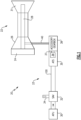
- Figure 1 shows an assembly 20 including a gas turbine engine 22 and a starter air system 23 for starting the gas turbine engine 22, and for providing rotation prior to startup.
- the gas turbine engine 22 includes a fan 24, a compressor section 26, a shaft 28 and a turbine 31, all of which are shown schematically. As known compressor section 26, shaft 28 and turbine 31 may all rotate together.
- An auxiliary power unit (APU) 30 provides air through a starter air valve 32.
- An actuation assembly 34 is shown for the starter air valve 32 to control the flow of air from an APU 30 downstream to an air turbine starter system 35.
- Air turbine starter system 35 includes a turbine 36 and a clutch 37. The air drives the turbine 36 to, in turn, drive gears within an accessory gearbox 38 and a drive a shaft 40, which drives the shaft 28 to turn gears in the gas turbine engine 22. This drive is shown schematically, and may be generally known.
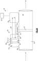
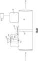
- the starter air valve 32 is shown in Figure 2A in a first mode.
- a line 52 has an inlet side 50 and an outlet side 54.
- a valve member 57 controls the flow of air through the line 52.
- the actuation assembly 34 includes a rotary spool valve 53 having inlet bore 55 receiving a tap to the pressurized air upstream of the inlet 50.
- a knob 58 allows selective control of the position of a rotatable valve body 56 of the rotary spool valve 53.
- Air flows through the rotary spool valve 53 into line 60, which communicates with an actuator control 62, that may be a solenoid, or torque motor.
- a structure within the actuator control 62 selectively allows, or blocks, flow of the air back into a line 64 returning to the rotary spool valve 53.
- An electronic control 63 is programmed to control the position of the actuator control 62. From rotor spool valve 53, the air downstream of line 64 passes into a line 66 heading to an actuator 158. The air then moves the actuator 158 to, in turn, adjust the position of the valve member 57.
- valve member 57 may be a butterfly disk.
- this disclosure extends to systems with other valve types.
- the rotary spool valve 53 includes an outer housing 70 surrounding a rotatable valve body 56.
- air from the bore 55 can pass through an opening 72 in a wall of the rotatable valve body 56 and into line 80 in the housing 70 to communicate with line 60.
- Line 64 is shown communicating with a line 82, which passes into a ditch 74 formed in an outer wall 104 of the rotatable valve body 56 to route the air back into a line 84, which communicates with line 66.
- another line 86 is shown blocked by outer wall 104 of the rotatable valve body 56.
- a port 78 is also shown within the rotatable valve body 56.
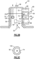
- FIG. 2C shows a cross-sectional along line 2C-2C of Figure 2B .
- the rotatable valve body 56 has the ditch 74 over a limited circumferential extent. At other locations, there is a nominal cylindrical outer surface 104 of the rotatable valve body 56. Ditch 74 has a smaller outer diameter of the nominal outer surface 104.
- Figure 3A shows the knob 58 having a head 186, which may be actuated to pull a moving plate 85 away from a plurality of balls 182, which are spring biased into detents in a fixed plate 180.
- Figure 3B shows plate 180 having detents 87.
- a spring 184 biases plate 85 and balls 182 into the detents 87.
- Plate 183 is also fixed.
- Figure 3C shows the head 186 and fixed plate 183.
- the Figure 2A position would be achieved with a technician inserting a wrench into a socket 90 and rotating until the normal, or start position, is aligned with an indicator 91 on a rotatable central portion. This will align the rotatable valve body 56 in the Figure 2B position.
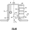
- FIG. 4A A second mode is shown in Figure 4A , the rotatable valve body 56 is now positioned such that air from the bore 55 is delivered into a line 92, which passes into the line 52 at a point 94, bypassing the valve member 57 which is in a closed position.
- This operation may be utilized when there is a failure between the actuator control 62 or the actuator 158.
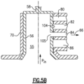
- Figure 5A shows a third mode of operation.
- the rotatable valve body 56 is rotated such that it communicates air from bore 55 directly into line 66 and to actuator 158.
- a port 105 now communicates air into the line 84 from the bore 55.
- nominal outer wall surface 104 blocks communication between line 82 and line 84. Again, in the prior art, this communication was not blocked.
- a starter air valve for an air turbine starter system under this disclosure could be said to include a valve member and an actuator.
- a rotary spool valve is to be connected to a source of pressurized air.
- the rotary spool valve has a rotatable valve body and an outer housing.
- the rotatable valve body and the valve housing selectively provide three modes of operation for the starter air valve, A first mode of operation connects pressurized air through the rotatable valve body to communicate with the actuator control, and to receive pressurized air back from the actuator control.
- the rotatable valve body then communicates the air to the actuator.
- the rotatable valve body blocks communication between the actuator control and the actuator, and delivers air through a variable area port in a wall of the rotatable valve body to bypass the valve member.
- the rotatable valve body block communication between the actuator and the actuator control, and connects pressurized air to the actuator without having passed to the actuator control.
Landscapes
- Engineering & Computer Science (AREA)
- General Engineering & Computer Science (AREA)
- Chemical & Material Sciences (AREA)
- Combustion & Propulsion (AREA)
- Mechanical Engineering (AREA)
- Physics & Mathematics (AREA)
- Fluid Mechanics (AREA)
- Multiple-Way Valves (AREA)
Claims (11)
- Soupape d'air de démarreur pour un système de démarreur de turbine à air comprenant :un élément de soupape (57) et un actionneur (158) pour ledit élément de soupape ;un distributeur à tiroir rotatif (53) à raccorder à une source d'air sous pression, ledit distributeur à tiroir rotatif ayant un corps de soupape rotatif (56) et un boîtier externe (70) ;une commande d'actionneur (62) pour ledit actionneur ;ledit corps de soupape rotatif et ledit boîtier externe fournissant sélectivement trois modes de fonctionnement pour la soupape d'air de démarreur ;dans un premier mode de fonctionnement le corps de soupape rotatif raccorde de l'air sous pression à travers ledit corps de soupape rotatif pour communiquer avec ladite commande d'actionneur, et reçoit à nouveau de l'air sous pression provenant de ladite commande d'actionneur, puis communique l'air audit actionneur ;dans un deuxième mode le corps de soupape rotatif bloque la communication entre ladite commande d'actionneur et ledit actionneur, et délivre de l'air à travers un orifice à section variable dans une paroi externe dudit corps de soupape rotatif pour contourner ledit élément de soupape ; etdans un troisième mode le corps de soupape rotatif bloque la communication entre ledit actionneur et ladite commande d'actionneur, et raccorde de l'air sous pression audit actionneur sans être passé par ladite commande d'actionneur.
- Soupape d'air de démarreur selon la revendication 1, dans laquelle ledit corps de soupape rotatif comportant ladite paroi externe (104) et ayant un fossé (74) d'un diamètre inférieur à une surface externe nominale de ladite paroi externe, ledit fossé raccorde sélectivement une conduite depuis ladite commande d'actionneur vers une conduite menant audit actionneur.
- Soupape d'air de démarreur selon la revendication 2, dans laquelle ladite commande d'actionneur est l'une parmi un solénoïde et un moteur couple.
- Soupape d'air de démarreur selon la revendication 3, dans laquelle un troisième orifice de mode s'étend à travers ladite paroi externe pour communiquer de l'air à ladite conduite menant audit actionneur dans ledit troisième mode de fonctionnement.
- Soupape d'air de démarreur selon la revendication 4, dans laquelle ledit corps de soupape rotatif peut être tourné manuellement avec un bouton (58) pour fonctionner dans lesdits premier, deuxième et troisième modes.
- Soupape d'air de démarreur selon la revendication 5, dans laquelle ledit bouton tourne par rapport à une plaque comportant des repères de positions pour lesdits premier, deuxième et troisième modes.
- Soupape d'air de démarreur selon la revendication 1, dans laquelle ledit élément de soupape est un disque papillon.
- Soupape d'air de démarreur selon la revendication 1, dans laquelle ladite commande d'actionneur est l'une parmi un solénoïde et un moteur couple.
- Soupape d'air de démarreur selon la revendication 1, dans laquelle un troisième orifice de mode s'étend à travers ladite paroi externe pour communiquer de l'air à une conduite menant audit actionneur dans ledit troisième mode de fonctionnement.
- Soupape d'air de démarreur selon la revendication 1, dans laquelle ledit corps de soupape rotatif peut être tourné manuellement avec un bouton pour fonctionner dans lesdits premier, deuxième et troisième modes.
- Système d'air de démarreur comprenant :une unité de puissance auxiliaire (30) pour délivrer de l'air à une soupape d'air de démarreur (32) ;un démarreur de turbine à air (35) raccordé pour recevoir de l'air en aval de ladite soupape d'air de démarreur, et pour entraîner un arbre (40) pour entraîner sélectivement la rotation d'un moteur à turbine à gaz ;dans lequel la soupape d'air de démarreur est telle que revendiquée selon une quelconque revendication précédente.
Applications Claiming Priority (1)
| Application Number | Priority Date | Filing Date | Title |
|---|---|---|---|
| US16/725,177 US11261796B2 (en) | 2019-12-23 | 2019-12-23 | Air turbine starter air valve |
Publications (2)
| Publication Number | Publication Date |
|---|---|
| EP3842627A1 EP3842627A1 (fr) | 2021-06-30 |
| EP3842627B1 true EP3842627B1 (fr) | 2023-08-23 |
Family
ID=73856122
Family Applications (1)
| Application Number | Title | Priority Date | Filing Date |
|---|---|---|---|
| EP20215981.0A Active EP3842627B1 (fr) | 2019-12-23 | 2020-12-21 | Soupape d'air de démarreur de turbine à air |
Country Status (2)
| Country | Link |
|---|---|
| US (1) | US11261796B2 (fr) |
| EP (1) | EP3842627B1 (fr) |
Family Cites Families (19)
| Publication number | Priority date | Publication date | Assignee | Title |
|---|---|---|---|---|
| US2961586A (en) * | 1957-12-23 | 1960-11-22 | E I M Company Inc | Anticipatory condiction control servosystem |
| FR2607189B1 (fr) * | 1986-11-20 | 1990-05-04 | Snecma | Dispositif de commande d'une vanne de demarrage de turbomachine d'aviation |
| US4916437A (en) * | 1987-08-14 | 1990-04-10 | Gazzaz Hesham H | Gas monitoring system with leak detection and flow cutoff |
| US4841816A (en) * | 1988-08-11 | 1989-06-27 | General Motors Corporation | Hydraulic control for a power transmission with a manual range selector valve |
| US6684898B2 (en) * | 2001-09-27 | 2004-02-03 | Honeywell International Inc. | Dual actuator air turbine starter valve |
| US6694746B2 (en) * | 2002-02-06 | 2004-02-24 | Honeywell International, Inc. | Micro volume actuator for an air turbine starter |
| JP4369292B2 (ja) * | 2004-05-06 | 2009-11-18 | タイコ フローコントロールジャパン株式会社 | 緊急遮断弁装置 |
| US7147430B2 (en) * | 2004-06-10 | 2006-12-12 | Honeywell International, Inc. | Pneumatic valve control using downstream pressure feedback and an air turbine starter incorporating the same |
| US7475863B2 (en) * | 2005-10-14 | 2009-01-13 | Rain Bird Corporation | Piston for reverse flow diaphragm valve |
| US8201572B2 (en) * | 2008-09-15 | 2012-06-19 | Segal Stanley H | Water supply control apparatus and method for use in homes or other structures |
| US20100085676A1 (en) * | 2008-10-03 | 2010-04-08 | Honeywell International Inc. | Nested pulse width modulation control |
| US9618129B2 (en) * | 2010-10-07 | 2017-04-11 | Vanderbilt University | Normally closed microvalve and applications of the same |
| US20120211681A1 (en) * | 2011-02-17 | 2012-08-23 | Easytork Automation Corporation | Pneumatic actuator air flow control system |
| US9157374B2 (en) * | 2012-08-31 | 2015-10-13 | Hamilton Sundstrand Corporation | Antirotated piston rack |
| US10301963B2 (en) | 2016-12-28 | 2019-05-28 | Hamilton Sundstrand Corporation | Starter air valve systems configured for low speed motoring |
| US10458337B2 (en) | 2017-01-20 | 2019-10-29 | Hamilton Sundstrand Corporation | Dual inline valve with manual override |
| US9957899B1 (en) | 2017-01-20 | 2018-05-01 | Hamilton Sundstrand Corporation | Dual inline starter air valve |
| US10711701B2 (en) | 2017-06-06 | 2020-07-14 | Hamilton Sunstrand Corporation | Manual bowed rotor and full override |
| US10634057B2 (en) | 2018-01-19 | 2020-04-28 | Hamilton Sundstrand Corporation | Airflow control for air turbine starter |
-
2019
- 2019-12-23 US US16/725,177 patent/US11261796B2/en active Active
-
2020
- 2020-12-21 EP EP20215981.0A patent/EP3842627B1/fr active Active
Also Published As
| Publication number | Publication date |
|---|---|
| US20210189968A1 (en) | 2021-06-24 |
| EP3842627A1 (fr) | 2021-06-30 |
| US11261796B2 (en) | 2022-03-01 |
Similar Documents
| Publication | Publication Date | Title |
|---|---|---|
| US11873771B2 (en) | Propeller assembly and pitch control unit | |
| US6684898B2 (en) | Dual actuator air turbine starter valve | |
| EP2929163B1 (fr) | Moteur à turbine à gaz présentant plusieurs voies d'air d'accessoires | |
| EP1472446B1 (fr) | Actionneur de vanne de demarreur de type turbine a air | |
| US9915201B2 (en) | Aircraft power system | |
| EP1918560B1 (fr) | Contrôle combiné pour fournir de l'air de refroidissement et de l'air de support dans une buse de moteur à turbine | |
| US10634057B2 (en) | Airflow control for air turbine starter | |
| JP2004502068A (ja) | 燃料供給装置において閉止、過回転防止、およびバイパス流れの方向制御を提供する方法および装置 | |
| EP3412896B1 (fr) | Entraînement manuel de rotor courbé et priorité complète | |
| EP2960468B1 (fr) | Moteur à double flux à engrenages avec système de contrôle de climatisation à basse pression pour aéronef | |
| EP1302640B1 (fr) | Propulseur additionnel avec cycle variable | |
| EP2192307A2 (fr) | Système de commande de pas de pale | |
| EP3683425B1 (fr) | Soupape de démarreur à régulation de pression | |
| CN109312665B (zh) | 用于燃气涡轮发动机的燃料输送系统和方法 | |
| EP3351744B1 (fr) | Soupape d'air de démarreur | |
| JPS631800A (ja) | コンプレッサおよびこれを用いた圧縮空気−発電装置 | |
| EP3572640B1 (fr) | Procédé de commande de compresseur de moteur de turbine à gaz | |
| EP3842627B1 (fr) | Soupape d'air de démarreur de turbine à air | |
| EP4438878B1 (fr) | Soupape de commande et démarreur de turbine à air combinés | |
| EP3351742B1 (fr) | Soupape d'air de démarreur double en ligne | |
| EP4484809A1 (fr) | Clapet à battant à direction de rotation commune |
Legal Events
| Date | Code | Title | Description |
|---|---|---|---|
| PUAI | Public reference made under article 153(3) epc to a published international application that has entered the european phase |
Free format text: ORIGINAL CODE: 0009012 |
|
| STAA | Information on the status of an ep patent application or granted ep patent |
Free format text: STATUS: THE APPLICATION HAS BEEN PUBLISHED |
|
| AK | Designated contracting states |
Kind code of ref document: A1 Designated state(s): AL AT BE BG CH CY CZ DE DK EE ES FI FR GB GR HR HU IE IS IT LI LT LU LV MC MK MT NL NO PL PT RO RS SE SI SK SM TR |
|
| STAA | Information on the status of an ep patent application or granted ep patent |
Free format text: STATUS: REQUEST FOR EXAMINATION WAS MADE |
|
| 17P | Request for examination filed |
Effective date: 20211230 |
|
| RBV | Designated contracting states (corrected) |
Designated state(s): AL AT BE BG CH CY CZ DE DK EE ES FI FR GB GR HR HU IE IS IT LI LT LU LV MC MK MT NL NO PL PT RO RS SE SI SK SM TR |
|
| GRAP | Despatch of communication of intention to grant a patent |
Free format text: ORIGINAL CODE: EPIDOSNIGR1 |
|
| STAA | Information on the status of an ep patent application or granted ep patent |
Free format text: STATUS: GRANT OF PATENT IS INTENDED |
|
| INTG | Intention to grant announced |
Effective date: 20230331 |
|
| RIN1 | Information on inventor provided before grant (corrected) |
Inventor name: VEILLEUX, JR., LEO J. Inventor name: GRIGOROV, BORIS N. |
|
| GRAS | Grant fee paid |
Free format text: ORIGINAL CODE: EPIDOSNIGR3 |
|
| GRAA | (expected) grant |
Free format text: ORIGINAL CODE: 0009210 |
|
| STAA | Information on the status of an ep patent application or granted ep patent |
Free format text: STATUS: THE PATENT HAS BEEN GRANTED |
|
| AK | Designated contracting states |
Kind code of ref document: B1 Designated state(s): AL AT BE BG CH CY CZ DE DK EE ES FI FR GB GR HR HU IE IS IT LI LT LU LV MC MK MT NL NO PL PT RO RS SE SI SK SM TR |
|
| REG | Reference to a national code |
Ref country code: GB Ref legal event code: FG4D |
|
| REG | Reference to a national code |
Ref country code: CH Ref legal event code: EP |
|
| REG | Reference to a national code |
Ref country code: DE Ref legal event code: R096 Ref document number: 602020016195 Country of ref document: DE |
|
| REG | Reference to a national code |
Ref country code: IE Ref legal event code: FG4D |
|
| REG | Reference to a national code |
Ref country code: LT Ref legal event code: MG9D |
|
| REG | Reference to a national code |
Ref country code: NL Ref legal event code: MP Effective date: 20230823 |
|
| REG | Reference to a national code |
Ref country code: AT Ref legal event code: MK05 Ref document number: 1602831 Country of ref document: AT Kind code of ref document: T Effective date: 20230823 |
|
| PG25 | Lapsed in a contracting state [announced via postgrant information from national office to epo] |
Ref country code: GR Free format text: LAPSE BECAUSE OF FAILURE TO SUBMIT A TRANSLATION OF THE DESCRIPTION OR TO PAY THE FEE WITHIN THE PRESCRIBED TIME-LIMIT Effective date: 20231124 |
|
| PG25 | Lapsed in a contracting state [announced via postgrant information from national office to epo] |
Ref country code: IS Free format text: LAPSE BECAUSE OF FAILURE TO SUBMIT A TRANSLATION OF THE DESCRIPTION OR TO PAY THE FEE WITHIN THE PRESCRIBED TIME-LIMIT Effective date: 20231223 |
|
| PG25 | Lapsed in a contracting state [announced via postgrant information from national office to epo] |
Ref country code: SE Free format text: LAPSE BECAUSE OF FAILURE TO SUBMIT A TRANSLATION OF THE DESCRIPTION OR TO PAY THE FEE WITHIN THE PRESCRIBED TIME-LIMIT Effective date: 20230823 Ref country code: RS Free format text: LAPSE BECAUSE OF FAILURE TO SUBMIT A TRANSLATION OF THE DESCRIPTION OR TO PAY THE FEE WITHIN THE PRESCRIBED TIME-LIMIT Effective date: 20230823 Ref country code: PT Free format text: LAPSE BECAUSE OF FAILURE TO SUBMIT A TRANSLATION OF THE DESCRIPTION OR TO PAY THE FEE WITHIN THE PRESCRIBED TIME-LIMIT Effective date: 20231226 Ref country code: NO Free format text: LAPSE BECAUSE OF FAILURE TO SUBMIT A TRANSLATION OF THE DESCRIPTION OR TO PAY THE FEE WITHIN THE PRESCRIBED TIME-LIMIT Effective date: 20231123 Ref country code: NL Free format text: LAPSE BECAUSE OF FAILURE TO SUBMIT A TRANSLATION OF THE DESCRIPTION OR TO PAY THE FEE WITHIN THE PRESCRIBED TIME-LIMIT Effective date: 20230823 Ref country code: LV Free format text: LAPSE BECAUSE OF FAILURE TO SUBMIT A TRANSLATION OF THE DESCRIPTION OR TO PAY THE FEE WITHIN THE PRESCRIBED TIME-LIMIT Effective date: 20230823 Ref country code: LT Free format text: LAPSE BECAUSE OF FAILURE TO SUBMIT A TRANSLATION OF THE DESCRIPTION OR TO PAY THE FEE WITHIN THE PRESCRIBED TIME-LIMIT Effective date: 20230823 Ref country code: IS Free format text: LAPSE BECAUSE OF FAILURE TO SUBMIT A TRANSLATION OF THE DESCRIPTION OR TO PAY THE FEE WITHIN THE PRESCRIBED TIME-LIMIT Effective date: 20231223 Ref country code: HR Free format text: LAPSE BECAUSE OF FAILURE TO SUBMIT A TRANSLATION OF THE DESCRIPTION OR TO PAY THE FEE WITHIN THE PRESCRIBED TIME-LIMIT Effective date: 20230823 Ref country code: GR Free format text: LAPSE BECAUSE OF FAILURE TO SUBMIT A TRANSLATION OF THE DESCRIPTION OR TO PAY THE FEE WITHIN THE PRESCRIBED TIME-LIMIT Effective date: 20231124 Ref country code: FI Free format text: LAPSE BECAUSE OF FAILURE TO SUBMIT A TRANSLATION OF THE DESCRIPTION OR TO PAY THE FEE WITHIN THE PRESCRIBED TIME-LIMIT Effective date: 20230823 Ref country code: AT Free format text: LAPSE BECAUSE OF FAILURE TO SUBMIT A TRANSLATION OF THE DESCRIPTION OR TO PAY THE FEE WITHIN THE PRESCRIBED TIME-LIMIT Effective date: 20230823 |
|
| PG25 | Lapsed in a contracting state [announced via postgrant information from national office to epo] |
Ref country code: PL Free format text: LAPSE BECAUSE OF FAILURE TO SUBMIT A TRANSLATION OF THE DESCRIPTION OR TO PAY THE FEE WITHIN THE PRESCRIBED TIME-LIMIT Effective date: 20230823 |
|
| PG25 | Lapsed in a contracting state [announced via postgrant information from national office to epo] |
Ref country code: ES Free format text: LAPSE BECAUSE OF FAILURE TO SUBMIT A TRANSLATION OF THE DESCRIPTION OR TO PAY THE FEE WITHIN THE PRESCRIBED TIME-LIMIT Effective date: 20230823 |
|
| PG25 | Lapsed in a contracting state [announced via postgrant information from national office to epo] |
Ref country code: SM Free format text: LAPSE BECAUSE OF FAILURE TO SUBMIT A TRANSLATION OF THE DESCRIPTION OR TO PAY THE FEE WITHIN THE PRESCRIBED TIME-LIMIT Effective date: 20230823 Ref country code: RO Free format text: LAPSE BECAUSE OF FAILURE TO SUBMIT A TRANSLATION OF THE DESCRIPTION OR TO PAY THE FEE WITHIN THE PRESCRIBED TIME-LIMIT Effective date: 20230823 Ref country code: ES Free format text: LAPSE BECAUSE OF FAILURE TO SUBMIT A TRANSLATION OF THE DESCRIPTION OR TO PAY THE FEE WITHIN THE PRESCRIBED TIME-LIMIT Effective date: 20230823 Ref country code: EE Free format text: LAPSE BECAUSE OF FAILURE TO SUBMIT A TRANSLATION OF THE DESCRIPTION OR TO PAY THE FEE WITHIN THE PRESCRIBED TIME-LIMIT Effective date: 20230823 Ref country code: DK Free format text: LAPSE BECAUSE OF FAILURE TO SUBMIT A TRANSLATION OF THE DESCRIPTION OR TO PAY THE FEE WITHIN THE PRESCRIBED TIME-LIMIT Effective date: 20230823 Ref country code: CZ Free format text: LAPSE BECAUSE OF FAILURE TO SUBMIT A TRANSLATION OF THE DESCRIPTION OR TO PAY THE FEE WITHIN THE PRESCRIBED TIME-LIMIT Effective date: 20230823 Ref country code: SK Free format text: LAPSE BECAUSE OF FAILURE TO SUBMIT A TRANSLATION OF THE DESCRIPTION OR TO PAY THE FEE WITHIN THE PRESCRIBED TIME-LIMIT Effective date: 20230823 |
|
| REG | Reference to a national code |
Ref country code: DE Ref legal event code: R097 Ref document number: 602020016195 Country of ref document: DE |
|
| PG25 | Lapsed in a contracting state [announced via postgrant information from national office to epo] |
Ref country code: IT Free format text: LAPSE BECAUSE OF FAILURE TO SUBMIT A TRANSLATION OF THE DESCRIPTION OR TO PAY THE FEE WITHIN THE PRESCRIBED TIME-LIMIT Effective date: 20230823 |
|
| PLBE | No opposition filed within time limit |
Free format text: ORIGINAL CODE: 0009261 |
|
| STAA | Information on the status of an ep patent application or granted ep patent |
Free format text: STATUS: NO OPPOSITION FILED WITHIN TIME LIMIT |
|
| 26N | No opposition filed |
Effective date: 20240524 |
|
| PG25 | Lapsed in a contracting state [announced via postgrant information from national office to epo] |
Ref country code: SI Free format text: LAPSE BECAUSE OF FAILURE TO SUBMIT A TRANSLATION OF THE DESCRIPTION OR TO PAY THE FEE WITHIN THE PRESCRIBED TIME-LIMIT Effective date: 20230823 |
|
| REG | Reference to a national code |
Ref country code: CH Ref legal event code: PL |
|
| PG25 | Lapsed in a contracting state [announced via postgrant information from national office to epo] |
Ref country code: LU Free format text: LAPSE BECAUSE OF NON-PAYMENT OF DUE FEES Effective date: 20231221 |
|
| PG25 | Lapsed in a contracting state [announced via postgrant information from national office to epo] |
Ref country code: MC Free format text: LAPSE BECAUSE OF FAILURE TO SUBMIT A TRANSLATION OF THE DESCRIPTION OR TO PAY THE FEE WITHIN THE PRESCRIBED TIME-LIMIT Effective date: 20230823 |
|
| REG | Reference to a national code |
Ref country code: BE Ref legal event code: MM Effective date: 20231231 |
|
| PG25 | Lapsed in a contracting state [announced via postgrant information from national office to epo] |
Ref country code: MC Free format text: LAPSE BECAUSE OF FAILURE TO SUBMIT A TRANSLATION OF THE DESCRIPTION OR TO PAY THE FEE WITHIN THE PRESCRIBED TIME-LIMIT Effective date: 20230823 Ref country code: LU Free format text: LAPSE BECAUSE OF NON-PAYMENT OF DUE FEES Effective date: 20231221 |
|
| REG | Reference to a national code |
Ref country code: IE Ref legal event code: MM4A |
|
| PG25 | Lapsed in a contracting state [announced via postgrant information from national office to epo] |
Ref country code: IE Free format text: LAPSE BECAUSE OF NON-PAYMENT OF DUE FEES Effective date: 20231221 |
|
| PG25 | Lapsed in a contracting state [announced via postgrant information from national office to epo] |
Ref country code: BE Free format text: LAPSE BECAUSE OF NON-PAYMENT OF DUE FEES Effective date: 20231231 |
|
| PG25 | Lapsed in a contracting state [announced via postgrant information from national office to epo] |
Ref country code: CH Free format text: LAPSE BECAUSE OF NON-PAYMENT OF DUE FEES Effective date: 20231231 |
|
| PG25 | Lapsed in a contracting state [announced via postgrant information from national office to epo] |
Ref country code: IE Free format text: LAPSE BECAUSE OF NON-PAYMENT OF DUE FEES Effective date: 20231221 Ref country code: CH Free format text: LAPSE BECAUSE OF NON-PAYMENT OF DUE FEES Effective date: 20231231 Ref country code: BE Free format text: LAPSE BECAUSE OF NON-PAYMENT OF DUE FEES Effective date: 20231231 |
|
| PG25 | Lapsed in a contracting state [announced via postgrant information from national office to epo] |
Ref country code: BG Free format text: LAPSE BECAUSE OF FAILURE TO SUBMIT A TRANSLATION OF THE DESCRIPTION OR TO PAY THE FEE WITHIN THE PRESCRIBED TIME-LIMIT Effective date: 20230823 |
|
| PG25 | Lapsed in a contracting state [announced via postgrant information from national office to epo] |
Ref country code: BG Free format text: LAPSE BECAUSE OF FAILURE TO SUBMIT A TRANSLATION OF THE DESCRIPTION OR TO PAY THE FEE WITHIN THE PRESCRIBED TIME-LIMIT Effective date: 20230823 |
|
| PG25 | Lapsed in a contracting state [announced via postgrant information from national office to epo] |
Ref country code: CY Free format text: LAPSE BECAUSE OF FAILURE TO SUBMIT A TRANSLATION OF THE DESCRIPTION OR TO PAY THE FEE WITHIN THE PRESCRIBED TIME-LIMIT; INVALID AB INITIO Effective date: 20201221 |
|
| PG25 | Lapsed in a contracting state [announced via postgrant information from national office to epo] |
Ref country code: HU Free format text: LAPSE BECAUSE OF FAILURE TO SUBMIT A TRANSLATION OF THE DESCRIPTION OR TO PAY THE FEE WITHIN THE PRESCRIBED TIME-LIMIT; INVALID AB INITIO Effective date: 20201221 |
|
| PG25 | Lapsed in a contracting state [announced via postgrant information from national office to epo] |
Ref country code: TR Free format text: LAPSE BECAUSE OF FAILURE TO SUBMIT A TRANSLATION OF THE DESCRIPTION OR TO PAY THE FEE WITHIN THE PRESCRIBED TIME-LIMIT Effective date: 20230823 |
|
| PGFP | Annual fee paid to national office [announced via postgrant information from national office to epo] |
Ref country code: DE Payment date: 20251126 Year of fee payment: 6 |
|
| PGFP | Annual fee paid to national office [announced via postgrant information from national office to epo] |
Ref country code: GB Payment date: 20251120 Year of fee payment: 6 |
|
| PGFP | Annual fee paid to national office [announced via postgrant information from national office to epo] |
Ref country code: FR Payment date: 20251120 Year of fee payment: 6 |
|
| P01 | Opt-out of the competence of the unified patent court (upc) registered |
Free format text: CASE NUMBER: UPC_APP_0018740_3842627/2025 Effective date: 20251221 |