EP3842637B1 - Wasserpumpvorrichtung und friseurgerät - Google Patents
Wasserpumpvorrichtung und friseurgerät Download PDFInfo
- Publication number
- EP3842637B1 EP3842637B1 EP20204075.4A EP20204075A EP3842637B1 EP 3842637 B1 EP3842637 B1 EP 3842637B1 EP 20204075 A EP20204075 A EP 20204075A EP 3842637 B1 EP3842637 B1 EP 3842637B1
- Authority
- EP
- European Patent Office
- Prior art keywords
- water
- water delivery
- pump core
- liquid
- delivery channel
- Prior art date
- Legal status (The legal status is an assumption and is not a legal conclusion. Google has not performed a legal analysis and makes no representation as to the accuracy of the status listed.)
- Active
Links
Images




Classifications
-
- A—HUMAN NECESSITIES
- A45—HAND OR TRAVELLING ARTICLES
- A45D—HAIRDRESSING OR SHAVING EQUIPMENT; EQUIPMENT FOR COSMETICS OR COSMETIC TREATMENTS, e.g. FOR MANICURING OR PEDICURING
- A45D1/00—Curling-tongs, i.e. tongs for use when hot; Curling-irons, i.e. irons for use when hot; Accessories therefor
-
- B—PERFORMING OPERATIONS; TRANSPORTING
- B05—SPRAYING OR ATOMISING IN GENERAL; APPLYING FLUENT MATERIALS TO SURFACES, IN GENERAL
- B05B—SPRAYING APPARATUS; ATOMISING APPARATUS; NOZZLES
- B05B9/00—Spraying apparatus for discharge of liquids or other fluent material, without essentially mixing with gas or vapour
- B05B9/03—Spraying apparatus for discharge of liquids or other fluent material, without essentially mixing with gas or vapour characterised by means for supplying liquid or other fluent material
- B05B9/04—Spraying apparatus for discharge of liquids or other fluent material, without essentially mixing with gas or vapour characterised by means for supplying liquid or other fluent material with pressurised or compressible container; with pump
- B05B9/08—Apparatus to be carried on or by a person, e.g. of knapsack type
- B05B9/085—Apparatus to be carried on or by a person, e.g. of knapsack type with a liquid pump
- B05B9/0855—Apparatus to be carried on or by a person, e.g. of knapsack type with a liquid pump the pump being motor-driven
- B05B9/0861—Apparatus to be carried on or by a person, e.g. of knapsack type with a liquid pump the pump being motor-driven the motor being electric
-
- F—MECHANICAL ENGINEERING; LIGHTING; HEATING; WEAPONS; BLASTING
- F04—POSITIVE - DISPLACEMENT MACHINES FOR LIQUIDS; PUMPS FOR LIQUIDS OR ELASTIC FLUIDS
- F04B—POSITIVE-DISPLACEMENT MACHINES FOR LIQUIDS; PUMPS
- F04B43/00—Machines, pumps, or pumping installations having flexible working members
- F04B43/12—Machines, pumps, or pumping installations having flexible working members having peristaltic action
- F04B43/1238—Machines, pumps, or pumping installations having flexible working members having peristaltic action using only one roller as the squeezing element, the roller moving on an arc of a circle during squeezing
-
- A—HUMAN NECESSITIES
- A45—HAND OR TRAVELLING ARTICLES
- A45D—HAIRDRESSING OR SHAVING EQUIPMENT; EQUIPMENT FOR COSMETICS OR COSMETIC TREATMENTS, e.g. FOR MANICURING OR PEDICURING
- A45D2/00—Hair-curling or hair-waving appliances ; Appliances for hair dressing treatment not otherwise provided for
- A45D2/001—Hair straightening appliances
-
- A—HUMAN NECESSITIES
- A45—HAND OR TRAVELLING ARTICLES
- A45D—HAIRDRESSING OR SHAVING EQUIPMENT; EQUIPMENT FOR COSMETICS OR COSMETIC TREATMENTS, e.g. FOR MANICURING OR PEDICURING
- A45D2/00—Hair-curling or hair-waving appliances ; Appliances for hair dressing treatment not otherwise provided for
- A45D2/36—Hair curlers or hair winders with incorporated heating or drying means, e.g. electric, using chemical reaction
-
- A—HUMAN NECESSITIES
- A45—HAND OR TRAVELLING ARTICLES
- A45D—HAIRDRESSING OR SHAVING EQUIPMENT; EQUIPMENT FOR COSMETICS OR COSMETIC TREATMENTS, e.g. FOR MANICURING OR PEDICURING
- A45D1/00—Curling-tongs, i.e. tongs for use when hot; Curling-irons, i.e. irons for use when hot; Accessories therefor
- A45D2001/008—Curling-tongs, i.e. tongs for use when hot; Curling-irons, i.e. irons for use when hot; Accessories therefor with vapor generation, e.g. steam
-
- A—HUMAN NECESSITIES
- A45—HAND OR TRAVELLING ARTICLES
- A45D—HAIRDRESSING OR SHAVING EQUIPMENT; EQUIPMENT FOR COSMETICS OR COSMETIC TREATMENTS, e.g. FOR MANICURING OR PEDICURING
- A45D2200/00—Details not otherwise provided for in A45D
- A45D2200/05—Details of containers
- A45D2200/054—Means for supplying liquid to the outlet of the container
- A45D2200/056—Reciprocating pumps, i.e. with variable volume chamber wherein pressure and vacuum are alternately generated
-
- B—PERFORMING OPERATIONS; TRANSPORTING
- B05—SPRAYING OR ATOMISING IN GENERAL; APPLYING FLUENT MATERIALS TO SURFACES, IN GENERAL
- B05B—SPRAYING APPARATUS; ATOMISING APPARATUS; NOZZLES
- B05B15/00—Details of spraying plant or spraying apparatus not otherwise provided for; Accessories
- B05B15/30—Dip tubes
-
- B—PERFORMING OPERATIONS; TRANSPORTING
- B05—SPRAYING OR ATOMISING IN GENERAL; APPLYING FLUENT MATERIALS TO SURFACES, IN GENERAL
- B05B—SPRAYING APPARATUS; ATOMISING APPARATUS; NOZZLES
- B05B9/00—Spraying apparatus for discharge of liquids or other fluent material, without essentially mixing with gas or vapour
- B05B9/03—Spraying apparatus for discharge of liquids or other fluent material, without essentially mixing with gas or vapour characterised by means for supplying liquid or other fluent material
- B05B9/04—Spraying apparatus for discharge of liquids or other fluent material, without essentially mixing with gas or vapour characterised by means for supplying liquid or other fluent material with pressurised or compressible container; with pump
- B05B9/0403—Spraying apparatus for discharge of liquids or other fluent material, without essentially mixing with gas or vapour characterised by means for supplying liquid or other fluent material with pressurised or compressible container; with pump with pumps for liquids or other fluent material
- B05B9/042—Spraying apparatus for discharge of liquids or other fluent material, without essentially mixing with gas or vapour characterised by means for supplying liquid or other fluent material with pressurised or compressible container; with pump with pumps for liquids or other fluent material with peristaltic pumps
-
- F—MECHANICAL ENGINEERING; LIGHTING; HEATING; WEAPONS; BLASTING
- F04—POSITIVE - DISPLACEMENT MACHINES FOR LIQUIDS; PUMPS FOR LIQUIDS OR ELASTIC FLUIDS
- F04B—POSITIVE-DISPLACEMENT MACHINES FOR LIQUIDS; PUMPS
- F04B23/00—Pumping installations or systems
- F04B23/02—Pumping installations or systems having reservoirs
- F04B23/025—Pumping installations or systems having reservoirs the pump being located directly adjacent the reservoir
-
- F—MECHANICAL ENGINEERING; LIGHTING; HEATING; WEAPONS; BLASTING
- F04—POSITIVE - DISPLACEMENT MACHINES FOR LIQUIDS; PUMPS FOR LIQUIDS OR ELASTIC FLUIDS
- F04B—POSITIVE-DISPLACEMENT MACHINES FOR LIQUIDS; PUMPS
- F04B43/00—Machines, pumps, or pumping installations having flexible working members
- F04B43/12—Machines, pumps, or pumping installations having flexible working members having peristaltic action
- F04B43/123—Machines, pumps, or pumping installations having flexible working members having peristaltic action using an excenter as the squeezing element
Definitions
- the present invention relates to the technical field of hairdressing devices.
- hairdressing devices are increasingly widely used.
- a hair straightener in order to reduce damage to hair during hair straightening, a steam hair straightener emerges on the market which is connected with a water delivery mechanism and evaporates water into steam during hair straightening so as to moisten the hair.
- an existing water delivery mechanism needs to be additionally provided with a hose as a water delivery pipe to deliver water.
- a hairdressing device with such a water delivery mechanism is known e.g. from patent application document EP2449910A1 .
- the patent WO2015/189057A1 discloses a pump for conveying a liquid, having at least one pump housing comprising at least one inlet and at least one outlet, and comprising an inner circumferential surface and a geometric axis, wherein an eccentric is arranged within the pump housing and the eccentric is moveable eccentrically relative to the pump housing around the geometric axis.
- a deformable element is arranged in a pump gap between the inner circumferential surface of the pump housing and an outer surface of the eccentric, wherein a conveying channel from the at least one inlet to the at least one outlet is formed by the deformable element and the inner circumferential surface of the pump housing and wherein, in addition, the deformable element is pressed against the pump housing by the outer surface of the eccentric along at least one section of the conveying channel in such a way that at least one displaceable seal of the conveying channel and at least one closed pump volume are formed in the conveying channel and which are displaceable by an eccentric movement of the eccentric for conveying the fluid along the conveying channel from the inlet to the outlet, wherein the outer surface of the eccentric has a structured surface area.
- the present invention provides a hairdressing device.
- the present invention provides a hairdressing device as defined in the independent claim 1.
- the liquid storage device comprises a tank, a water guide pipe, and a first water suction member, wherein the water guide pipe has one end passing through the water tank and to be communicated with the outside, and an opposite end connected to the first water suction member; and the first water suction member has one end disposed on the water guide pipe and an opposite end extending in the tank.
- the hairdressing device according to the present invention have the benefits as follows.
- a first embodiment of the present invention provides a water pumping device 10 for being connected with a liquid storage device so as to deliver a liquid in the liquid storage device.
- the water pumping device 10 comprises a chamber p for containing the liquid and a squeezing device 14.
- the chamber p is defined by a hard wall surface and a deformable wall surface. In some embodiments, the chamber p may be entirely defined by the deformable wall surface.
- the water pumping device 10 comprises a flexible pump core 11, an outer bracket 12 and a baffle 13, the outer bracket 12 sleeving the flexible pump core 11, and the baffle 13 being disposed between the flexible pump core 11 and the outer bracket 12, extending from one of the flexible pump core 11 and the outer bracket 12 and being positioned on the other of the flexible pump core 11 and the outer bracket 12.
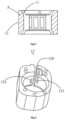
- FIG. 3 shows a schematic sectional view of the chamber p.
- the flexible pump core 11 is made of the deformable material.
- the flexible pump core 11 is ring-shaped (as shown in FIG. 5 ).
- the outer bracket 12 takes the shape of a ring with a notch 120 (as shown in FIG. 4 ).
- the baffle 13 is fixed to the flexible pump core 11, and the end of the baffle 13 away from the flexible pump core 11 is clamped into the notch 120 of the outer bracket 12.
- the baffle 13 may be fixed to the outer bracket 12, and the end of the baffle 13 away from the outer bracket 12 is tightly attached to the flexible pump core 11 as long as the baffle 13 is disposed between the flexible pump core 11 and the outer bracket 12 and separates a first water delivery channel 121 and a second water delivery channel 122.
- the baffle 13 is made of the deformable material.
- the thickness of the side of the baffle 11 close to the flexible pump core 11 is less than that of the side thereof away from the flexible pump core 11.
- the chamber p takes the shape of a ring with an opening.
- the baffle 13 is located at the opening of the chamber p.
- the squeezing device 14 is an eccentric wheel 141. In some embodiments, the squeezing device 14 may be a circular roller or others.
- the chamber p may take other shapes, such as a fan shape, an elliptic shape with an opening, and a linear shape as long as two opposite ends of the chamber p are communicated with the first water delivery channel 121 and the second water delivery channel 122 respectively.
- the squeezing device 13 periodically squeezes the deformable material from one end of the chamber p to the other end thereof to make the first water delivery channel 121 pump water and the second water delivery channel 122 deliver water.
- the flexible pump core 11 may be entirely made of the deformable material. By changing the thickness of the deformable material, the flexible pump core 11 may be partially supported.
- the flexible pump core 11 has thicker upper and lower surfaces, which may support the flexible pump core 11 and thus the flexible pump core 11 has certain shape.
- the flexible pump core 11 has a relatively thin middle portion which may be subjected to certain deformation by squeezing and may basically return to its original shape when the squeezing force is removed.
- the flexible pump core 11 is made of rubber.
- the flexible pump core 11 is subjected to certain deformation when being squeezed and the chamber p has a good sealing property to prevent water leakage.
- the flexible pump core 11 may also be made of other deformable materials, such as silica gel, as long as the flexible pump core 11 may be subjected to certain deformation when being squeezed and the chamber p has good sealing property.
- the interior of the flexible pump core 11 may be partially made of the deformable material and deformed by squeezing or entirely made of the deformable material and deformed by squeezing as long as a portion, in contact with the squeezing device 14, of the flexible pump core 11 is made of the deformable material, and may be deformed by squeezing.
- the outer bracket 12 may be entirely made of a hard material, partially made of a hard material and partially made of a deformable material, or entirely made of a deformable material with a low deformation degree as long as the outer bracket 12 plays a role of supporting when sleeving the flexible pump core 11, and defines, together with the flexible pump core 11, the chamber p.
- the first water delivery channel 121 and the second water delivery channel 122 are disposed on the outer bracket 12, and the two opposites ends of the chamber p are communicated with the first water delivery channel 121 and the second water delivery channel 122 respectively.
- the first water delivery channel 121 is connected with the liquid storage device.
- a wall surface of the chamber p is at least partially made of the deformable material.
- the squeezing device 14 periodically squeezes the deformable material from one end of the chamber p to the other end thereof to make the first water delivery channel 121 pump water and the second water delivery channel 122 deliver water.
- the water pumping device 10 further comprises an inner bracket 15 (as shown in FIG. 6 ).
- the inner bracket 15 is fixed inside the flexible pump core 11 (as shown in FIG. 5 ) and is made of a hard material.
- the squeezing device 14 drives the inner bracket 15 to periodically squeeze the flexible pump core 11 from one end of the chamber p to the other end thereof to make the first water delivery channel 121 pump water and the second water delivery channel 122 deliver water.
- the squeezing device 14 is not in direct contact with the flexible pump core 11, but it squeezes the flexible pump core 11 by driving the inner bracket 15, so that the wear of the flexible pump core 11 can be reduced.
- the squeezing contact surface is increased.
- the efficiency of squeezing the flexible pump core by the squeezing device 14 can be improved, the load can be reduced, and thus the liquid is delivered more uniformly.
- the arrow indicates a movement direction of the squeezing device 14.
- the squeezing device 14 drives the inner bracket 15 to squeeze the flexible pump core 11 from one end of the chamber p to the other end thereof so as to divide the chamber p into a water inlet chamber p1 and a water outlet chamber p2.
- the water inlet chamber p1 is located on a back side in the movement direction of the squeezing device 14 and the water outlet chamber p2 is located on a front side in the movement direction of the squeezing device 14. It may be understood that when the squeezing device 14 continues to move from the state shown in FIG.
- the water inlet chamber p1 will generate negative pressure and the liquid is pumped into the water inlet chamber p1 from the first water delivery channel 121.
- the water outlet chamber p2 will generate positive pressure and the liquid in the water outlet chamber p2 is discharged from the second water delivery channel 122.
- the squeezing device 14 moves to the state shown in FIG. 8 , the liquid in the water outlet chamber p2 is discharged.
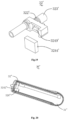
- the water pumping device 10 further comprises an upper cover 16 with a first convex member 163 (as shown in FIG. 9 ) and a lower cover 17 with a second convex member 173 (as shown in FIG. 10 ).
- the flexible pump core 11 is provided with a first concave member 112 and a second concave member 113 (as shown in FIG. 5 ).
- the first convex member 163 matches the first concave member 112 in structure and the second convex member 173 matches the second concave member 113 in structure.
- the first convex member 163 squeezes the first concave member 112, so that the first concave member 112 is tightly attached to the outer bracket 12.
- the second convex member 173 squeezes the second concave member 113, so that the second concave member 113 is tightly attached to the outer bracket 12.
- the chamber p has good sealing property to prevent liquid leakage.
- a first water delivery pipe 161 is disposed on the upper cover 16 and a second water delivery pipe 171 is disposed on the lower cover 17.
- the flexible pump core 11 is provided with water delivery holes 111 in positions corresponding to the first water delivery channel 121 and the second water delivery channel 122.
- a first groove 123 and a first boss 162 that match each other are disposed on surfaces, facing each other, of the outer bracket 12 and the upper cover 16 respectively (as shown in FIG. 11 ).
- the first boss 162 is inserted into the first groove 123, the first water delivery pipe 161 is correspondingly communicated with the first water delivery channel 121 through the water delivery hole 111.
- a second groove 124 and a second boss 172 that match each other are disposed on surfaces, facing each other, of the outer bracket 12 and the lower cover 17 respectively (as shown in FIG. 12 ).
- the second boss 172 is inserted into the second groove 124, the second water delivery pipe 171 is correspondingly communicated with the second water delivery channel 122 through the water delivery hole 111.
- one of the first groove 123 and the first boss 162 is disposed on the outer bracket 12 and the other is disposed on the upper cover 16.
- One of the second groove 124 and the second boss 172 is disposed on the outer bracket 12 and the other is disposed on the lower cover 17.
- the device may be used by directly connecting water pipes with the first water delivery pipe 161 and the second water delivery pipe 171 and it is convenient to pump water into the water pumping device 10 from the liquid storage device and introduce the liquid into other devices after the liquid is delivered out of the water pumping device 10.
- first groove 123 and the first boss 162 as well as the second groove 124 and the second boss 172 are disposed, when the outer bracket 12 is connected with the upper cover 16 and the lower cover 17, it is convenient to accurately butt the first water delivery pipe 161 and the first water delivery channel 121 and butt the second water delivery pipe 171 and the second water delivery channel 122, thereby preventing water leakage caused by inaccurate butting.
- the rigidity of the outer bracket 12 can be limited, and shaking due to a squeezing force of the squeezing device 14 and the outer bracket 12 is avoided during working, thereby improving the stability of delivering the liquid.
- the fixing of the outer bracket 12 ensures the forming of the flexible pump core 11, thereby improving the liquid delivery effect.
- the squeezing device 14 comprises an eccentric wheel 141, a swing bearing 142, a motor 143 and a reduction gear assembly 144.
- the motor 143 and the eccentric wheel 141 are connected through the reduction gear assembly 144.
- the motor 143 decelerates through the reduction gear assembly 144, so that the movement speed of the eccentric wheel 141 matches the optimal water outlet frequency.
- the swing bearing 142 is disposed on the eccentric wheel 141, and is tightly attached to the deformable material.
- the motor 143 rotates to drive, through the reduction gear assembly 144, the eccentric wheel 141 to move, and thus drive the swing bearing 142 to periodically squeeze the deformable material from one end of the chamber p to the other end thereof to make the first water delivery channel 121 pump water and the second water delivery channel 122 deliver water. Since the swing bearing 142 is tightly attached to the deformable material, the swing bearing 142 is driven through the eccentric wheel 141 during squeezing and there is less friction between the swing bearing 142 and the deformable material, which can reduce the wear of the deformable material and prolongs the service life of the water pumping device 10.
- the squeezing device 14 further comprises a driving shaft 145, a driven shaft 146 and a sealing member 147.
- the driving shaft 145 is connected with the reduction gear assembly 144
- the driven shaft 146 is connected with the driving shaft 145 and the eccentric wheel 141
- the sealing member 147 is disposed between the driving shaft 145 and the driven shaft 146.
- the eccentric wheel 141 may be separated from the reduction gear assembly 144 without affecting the movement of the eccentric wheel 141 to achieve the effect of water and electricity separation and improve the use safety of the water pumping device 10.
- an accommodating groove q is formed in the lower cover 17 and the motor 143 is accommodated in this accommodating groove q. As such, a fixing effect is achieved when the motor rotates 143, and thus the liquid return caused by shaking of the motor 143 is avoided.
- the first water delivery channel 121 and the second water delivery channel 122 may be disposed on the flexible pump core 11, or one of the first water delivery channel 121 and the second water delivery channel 122 is disposed on the flexible pump core 11 and the other is disposed on the outer bracket 12 as long as the first water delivery channel 121 is connected with the liquid storage device and the two opposite ends of the chamber p are communicated with the first water delivery channel 121 and the second water delivery channel 122 respectively.
- the flexible pump core 11 may be provided with no water delivery hole 111.
- the first water delivery pipe 161 directly corresponds to the first water delivery channel 121 and the second water delivery pipe 171 directly corresponds to the second water delivery channel 122 as long as the first water delivery pipe 161 is correspondingly communicated with the first water delivery channel 121 when the first boss 162 is inserted into the first groove 123, and the second water delivery pipe 171 is correspondingly communicated with the second water delivery channel 122 when the second boss 172 is inserted into the second groove 124.
- the first boss 162 may also be disposed on an edge of the surface, facing the outer bracket 12, of the upper cover 16, and at the same time, the first groove 123 is formed in a corresponding position of the surface, facing the upper cover 16, of the outer bracket 12, so that when the upper cover 16 is connected with the outer bracket 12, the first boss 162 is just inserted into the first groove 123; or the first groove 123 is formed in a corresponding position of the periphery of the outer bracket 12, so that when the upper cover 16 is connected with the outer bracket 12, the first boss 162 is just clamped in the first groove 123.
- the second boss 172 may also be disposed on an edge of the surface, facing the outer bracket 12, of the lower cover 17, and at the same time, the second groove 124 is formed in a corresponding position of the surface, facing the lower cover 17, of the outer bracket 12, so that when the lower cover 17 is connected with the outer bracket 12, the second boss 172 is just inserted into the second groove 124; or the second groove 124 is formed in a corresponding position of the periphery of the outer bracket 12, so that when the lower cover 17 is connected with the outer bracket 12, the second boss 172 is just clamped in the second groove 124.
- the outer bracket 12 is connected with the upper cover 16 and the lower cover 17 by any of magnetic attraction, clamping and threaded connection.
- the connection mode of the outer bracket 12 with the upper cover 16 and the lower cover 17 is not limited as long as the outer bracket 12 may be tightly connected with the upper cover 16 and the lower cover 17 and the disassembly is convenient for facilitating cleaning and maintenance of the internal structure of the water pumping device 10.
- liquid storage device 30 for supplying a liquid to an external device (such as a hairdressing device, a humidifier, and a face-cleaning device).
- the liquid storage device 30 comprises a tank 31, a water guide pipe 32, and a first water suction member 33. A portion of the water guide pipe 32 and the first water suction member 33 are embedded into the tank 31, and the first water suction member 33 is communicated with the water guide pipe 32.
- a communication mode of the first water suction member 33 and the water guide pipe 32 is specifically that one end of the first water suction member 33 is placed in the water guide pipe 32 and an opposite end of the first water suction member 33 extends to a wall surface, away from the water guide pipe 32, in the tank 31.
- the water guide pipe 32 runs through the tank 31 and is partially exposed to the tank 31.
- the water guide pipe 32 is configured to output the liquid to the external device
- the tank 31 is configured to store the liquid
- the first water suction member 33 is configured to suck the liquid in the tank 31 and output the liquid to the outside through the water guide pipe 32.
- the water guide pipe 32 may be connected with a water pump, through which the liquid in the tank 31 is discharged.
- a water pump for example, in a steam hair-straightening device, the liquid in the tank 31 is pumped out through a peristaltic pump.
- the water guide pipe 32 is in interference fit with the first water suction member 33, so that a connection position of the water guide pipe 32 and the first water suction member 33 is sealed, thereby avoiding the failure of pumping water due to loose connection and improving the stability of pumping water.
- the tank 31 comprises a first housing 311 and a second housing 312.
- the first housing 311 is buckled on the second housing 312.
- the first water suction member 33 and a portion of the water guide pipe 32 are disposed in this accommodating space.
- This accommodating space is configured to store the liquid.
- a water outlet 3121 is formed in the second housing 312.
- the water guide pipe 32 runs through the second housing 312 through the water outlet 3121 so as to output the liquid in the tank 31 to the external device.
- an end, away from the water guide pipe 32, of the first water suction member 33 has an increased weight due to liquid suction and may move in the tank 31.
- the end, away from the water guide pipe 32, of the first water suction member 33 may move to a liquid position to suck the liquid and then output the liquid to the water guide pipe 32.
- a load block 3248 is disposed at the end, away from the water guide pipe 32, of the first water suction member 33, so that when the tank 31 is in a holding state, the end of the first water suction member 33 with the load block 3248 may move in the tank 31 to the position where the liquid is located in the tank 31. Thus, it is ensured that the first water suction member 33 may output liquid.
- At least one first through hole 321 is formed in the water guide pipe 32 at a position corresponding to the first water suction member 33, and a position, corresponding to the first through hole 321, of the first water suction member 33 is exposed to the first through hole 321. It may be understood that by forming the first through hole 321 in the water guide pipe 32, the liquid at the position, where the water guide pipe 32 is located, in the tank 31 may be in contact with the first water suction member 33.
- the liquid When there is ;little liquid stored in the tank 31, the liquid may be accumulated at the position where the water guide pipe is located by reversing the tank 31 and then is sucked by the first water suction member 33 at the through hole 321, thereby improving the utilization rate of the liquid of the liquid storage device 30. Further, the position, corresponding to the first through hole 321, of the first water suction member 33 is exposed to be in contact with the liquid, a contact surface between the first water suction member 33 and the liquid is increased and the water suction area of the first water suction member 33 is increased. Thus, the suction and utilization rate of the liquid of the liquid storage device 30 is increased.
- the water guide pipe 32 is made of a flexible material, so that the water guide pipe 32 may be elastically deformed at the position of the first through hole 321, that is, the first through hole 321 may be deformed to increase the movement range of the first water suction member 33.
- the end, away from the water guide pipe 32, of the water suction member 33 may move to more positions in the tank 31 to suck the liquid, thereby increasing the utilization rate of the liquid in the tank 31.
- the first through hole 321 is in interference fit with the first water suction member 33 to maintain the sealing therebetween and thus prevent the failure of water suction due to air leakage by the first through hole 321.
- the first housing 311 comprises a water injection hole 3111, a cover 3112, a barrier 3113, and a vent hole 3114.
- the water injection hole 3111 and the vent hole 3114 run through the first housing 311.
- the cover 3112 matches the water injection hole 3111 and covers the water injection hole 3111.
- the barrier 3113 runs through the first housing 311.
- the cover 3112 is configured to block the water injection hole 3111 during use.
- the water injection hole 3111 is configured for injection of the liquid into the tank 31.
- the vent hole 3114 is configured to keep the air pressure in the tank 31 balanced.
- the barrier 3113 is configured to block the vent hole 3114.
- a user may inject the liquid into the tank 31 through the water injection hole 3111 and the cover 3112 may seal the water injection hole 3111, so that the tank 31 filled with the liquid keeps a sealed state.
- the vent hole 3114 may keep the air pressure inside and outside the tank 31 balanced.
- the barrier 3113 may block the vent hole 3114 to prevent the liquid from leaking from the vent hole 3114.
- an auxiliary water suction assembly 324 is disposed on a side, close to the water outlet 3121, of the water guide pipe 32.
- the auxiliary water suction assembly 324 extends in a direction away from the water guide pipe 32 and is configured to suck the liquid, close to the water outlet 3121, in the tank 31.
- the auxiliary water suction assembly 324 is disposed at a position, close to the water outlet 3121, of the tank 31 so as to suck the liquid at the water outlet 3121 in the tank 31. It may be understood that when there is little liquid in the tank 31, the auxiliary water suction assembly 324 may normally provide the liquid while the first water suction member 33 of the liquid storage device 30 provides little liquid, thereby increasing the liquid utilization rate of the liquid storage device 30.
- the auxiliary water suction assembly 324 comprises an auxiliary water suction pipe 3241 and a second water suction member 3242.
- the auxiliary water suction pipe 3241 is disposed on the side, close to the water outlet 3121, of the water guide pipe 32, extends towards the direction away from the water guide pipe 32 and is communicated with the water guide pipe 32.
- At least one second through hole 3243 is formed in the auxiliary water suction pipe 3241.
- the auxiliary water suction pipe 3241 is configured to deliver liquid sucked by the second water suction member 3242.
- the second water suction member 3242 is configured to suck the liquid close to the water outlet 3121 in the tank 31.
- the second through hole 3243 is configured to increase the contact surface between the second water suction member 3242 and the liquid.
- the second water suction pipe 3242 is embedded into the auxiliary water suction pipe 3241 and has a length greater than that of the auxiliary water suction pipe 3241, so that one end of the second water suction member 3242 is exposed to the auxiliary water suction pipe 3241.
- the auxiliary water suction pipe 3241 has one end connected with a pipe body of the water guide pipe 32 and an opposite end thereof extending towards the inner surface of the tank 31. The end, away from the water guide pipe 32, of the second water suction member 3242 sucks the liquid and delivers the liquid to the water guide pipe 32, so that the liquid at the position where the second water suction member 3242 is away from the water outlet 3121, in the tank is used.
- the second water suction member 3242 may have a length less than or equal to that of the auxiliary water suction pipe 3241 as long as the second water suction member 3242 may be placed in the auxiliary water suction pipe 3241 and sucks water.
- the first water suction member 33 and the second water suction member 3242 may be a cotton stick or other materials having a wicking effect.
- the number of the second through hole 3242 is one, but is not limited in this embodiment.
- the auxiliary water suction pipe 3241 extends to the inner surface of the tank 31 to increase the utilization rate of the liquid in the tank 31.
- the water guile pipe 32 adopts the structure of a T-shaped three-way pipe. It may be understood that the auxiliary water suction pipe 3241 and the water guide pipe 32 are vertically disposed.
- the auxiliary water suction pipe 3241 and the wall surface of the end, close to the water outlet 3121, the tank 31 have the same size, which can increase the utilization rate of the liquid at a lower water level.
- an auxiliary water suction assembly 324' comprises a water suction block 3244' and a drainage member 3245'.
- the water suction block 3244' is disposed on a side, close to the inner surface of a tank 31', of the drainage member 3245'.
- the drainage member 3245' is communicated with a water guide pipe 32'.
- the drainage member 3245' comprises at least one drainage port 3249' communicated with the water guide pipe 32'.
- the water suction block 3244' is disposed on the drainage port 3249'.
- the water suction block 3244' is configured to suck the liquid in the tank 31' and discharge the liquid through the drainage member 3245'.
- the drainage member 3245' is configured to discharge the liquid close to a water outlet 3121' in the tank 31'.
- the drainage member 3245' is provided with a drainage port 3249' on the side close to the surface of the tank 31'.
- the water suction block 3244' is in contact with the inner surface of the tank 31' and is in interference connection with the drainage port 3249'.
- the water suction block 3244' sucks liquid close to the water outlet 3121', in the tank 31' and discharges the liquid through the drainage member 3245', so that the liquid close to the water outlet 3121' in the tank 31' is sucked by the water suction block 3244', thereby increasing the utilization rate of the liquid in the tank 31'.
- the water suction block 3244' may be any of water suction materials such as a cotton stick and sponge.
- the water guide pipe 32' comprises a compression portion 122' and a connection portion 123'.
- the connection portion 123' is connected with one end of the first water suction member 33' and the compression portion 122' is compressible.
- the first water suction member 33' approaches the water guide pipe 32' by compressing the compression portion 122', so that the liquid, close to the water guide pipe 32', in the tank 31' is sucked by the first water suction member 33' and is delivered to the external device. Further, the first water suction member 33' compresses the compression portion 122' to move in the tank 31', thereby increasing the movement range of the first water suction member 33'.
- the number of the drainage port 3249' is one, but is not limited in this embodiment.
- the water suction block 3244' is in interference fit with the drainage member 3245', so that a connection position of the water suction block 3244' and the drainage member 3245' is sealed, thereby avoiding the failure of pumping water due to loose connection and improving the stability of pumping water.
- an auxiliary water suction assembly 324" comprises a water flow pipe 3246", a fixed pipe 3247” and a second water suction member 3242".
- the water flow pipe 3246" is positioned on a pipe body of the fixed pipe 3247", and a water guide pipe 32", the water flow pipe 3246" and the fixed pipe 3247” are sequentially disposed and communicated to form a structure of an H-shaped four-way pipe.
- the second water suction member 3242" is embedded into the fixed pipe 3247".
- At least one second through hole 3243" is formed in the fixed pipe 3247".
- the second through hole 3243" is formed in the side, away from the water flow pipe 3246", of the fixed pipe 3247".
- the fixed pipe 3247" two ends the fixed pipe 3247" are open.
- the second water suction member 3242" is embedded into the fixed pipe 3247” and may be in contact with liquid through two ends exposed to the fixed pipe 3247".
- the liquid at the position of the fixed pipe 3247" is further utilized.
- the user may tilt the liquid in a tank 330" towards this position, so that the second water suction member 3242” may suck the liquid.
- the second through hole 3243" is formed in the fixed pipe 3247” to increase the contact area between the second water suction member 3242" and the liquid, thereby increasing the utilization rate of the liquid.
- the second water suction member 3242" may have a length less than, greater than or equal to the length of the fixed pipe 3247" as long as the second water suction member 3242" is fixed in the fixed pipe 3247" and sucks water.
- the number of the through hole 3242" is one, but is not limited in this embodiment.
- an embodiment of the present invention provides a hairdressing device 20.
- the hairdressing device 20 may comprise the water pumping device 21 and the liquid storage device 22 according to the present invention.
- the liquid storage device 22 is connected with the water pumping device 21.
- the hairdressing device 20 may be configured to straighten hair, curl hair, dye hair and nourish hair, which is not specifically limited in the embodiment of the present invention.
- the chamber p has a volume of 0.01-0.1 ml
- the squeezing device has a squeezing speed of 40-90 r/min to the chamber and the water pumping device 21 works at this volume and the squeezing speed, which can make the amount of liquid delivered from the water pumping device 21 and the liquid delivery frequency suitable for the hairdressing device 20, without negatively affecting hairdressing of the hairdressing device 20 due to too little or too much liquid delivered.
- the hairdressing device 20 when being used, usually needs to be held and used at many angles (for example, a portable steam hair straightener needs to be lifted to meet the requirements of straightening hair at various angles).
- the liquid storage device 22 in the device also needs to subject to angle change, and the liquid in the liquid storage device 22 will move to different positions.
- the liquid When the liquid moves close to the water outlet, the liquid may be continued to be sucked through the liquid storage device 22.
- the utilization rate of the liquid is increased and the failure of water suction due to liquid inversion is avoided.
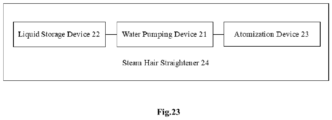
- FIG. 23 which shows a steam hair straightener 24 deformed from the hairdressing device 20.
- the steam hair straightener 24 comprises an atomization device 23. Liquid delivered from the second water delivery pipe of the water pumping device 21 passes through the atomization device 23 to form steam.
Landscapes
- Engineering & Computer Science (AREA)
- Mechanical Engineering (AREA)
- General Engineering & Computer Science (AREA)
- Jet Pumps And Other Pumps (AREA)
- Reciprocating Pumps (AREA)
- Massaging Devices (AREA)
- Cleaning And Drying Hair (AREA)
- Coating Apparatus (AREA)
Claims (10)
- Frisiergerät (20) mit einer Wasserpumpvorrichtung (10) und einer Flüssigkeitsspeichervorrichtung (30), die miteinander verbunden sind;wobei die Wasserpumpvorrichtung (10) eine Kammer (p) zur Aufnahme einer Flüssigkeit und eine Quetschvorrichtung (14) umfasst;wobei zwei gegenüberliegende Enden der Kammer (p) mit einem ersten Wasserzufuhrkanal (121) bzw. einem zweiten Wasserzufuhrkanal (122) verbunden sind, wobei der erste Wasserzufuhrkanal (121) mit der Flüssigkeitsspeichervorrichtung (30) verbunden ist und eine Wandoberfläche der Kammer (p) zumindest teilweise aus einem verformbaren Material besteht;dadurch gekennzeichnet, dass die Wasserpumpenvorrichtung (10) ferner eine innere Halterung (15) und einen flexiblen Pumpenkern (11) umfasst, wobei die innere Halterung (15) aus einem harten Material besteht, der flexible Pumpenkern (11) aus dem verformbaren Material besteht und die innere Halterung (15) im flexiblen Pumpenkern (11) befestigt ist;wobei die Quetschvorrichtung (14) die innere Halterung (15) antreibt, um den flexiblen Pumpenkern (11) periodisch von einem Ende der Kammer (p) zu ihrem anderen Ende zusammenzudrücken, um den ersten Wasserzufuhrkanal (121) dazu zu bringen, Wasser zu pumpen und den zweiten Wasserzufuhrkanal (122) dazu zu bringen, Wasser abzugeben; undwobei die Quetschvorrichtung (14) ein Exzenterrad (141) und ein Schwinglager (142) umfasst, wobei das Schwinglager (142) auf dem Exzenterrad (141) angeordnet und fest mit dem verformbaren Material verbunden ist.
- Frisiergerät (20) nach Anspruch 1, wobei die Kammer (p) durch eine harte Wandfläche und eine verformbare Wandfläche definiert ist; und zwischen dem ersten Wasserzufuhrkanal (121) und dem zweiten Wasserzufuhrkanal (122) keine Schlauchstruktur vorhanden ist.
- Frisiergerät (20) nach Anspruch 2, wobei die Wasserpumpvorrichtung (10) eine äußere Halterung (12) und eine Trennwand (13) umfasst, wobei die äußere Halterung (12) den flexiblen Pumpenkern (11) umhüllt, und die Trennwand (13) zwischen dem flexiblen Pumpenkern (11) und der äußeren Halterung (12) angeordnet ist, sich von einem der beiden erstreckt, nämlich dem flexiblen Pumpenkern (11) und der äußeren Halterung (12) und auf dem anderen der beiden positioniert ist, nämlich dem flexiblen Pumpenkern (11) und der äußeren Halterung (12).
- Frisiergerät (20) nach Anspruch 3, wobei die Wasserpumpvorrichtung (10) ferner eine obere Abdeckung (16) mit einem ersten konvexen Element (163) und eine untere Abdeckung (17) mit einem zweiten konvexen Element (173) umfasst; der flexible Pumpenkern (11) ist mit einem ersten konkaven Element (112) und einem zweiten konkaven Element (113) versehen, wobei das erste konvexe Element (163) in seiner Struktur dem ersten konkaven Element (112) entspricht und das zweite konvexe Element (173) in seiner Struktur dem zweiten konkaven Element (113) entspricht;wenn die obere Abdeckung (16) mit der äußeren Halterung (12) verbunden ist, drückt das erste konvexe Element (163) das erste konkave Element (112) zusammen, so dass das erste konkave Element (112) fest an der äußeren Halterung (12) angebracht ist; und wenn die untere Abdeckung (17) mit der äußeren Halterung (12) verbunden ist, drückt das zweite konvexe Element (173) das zweite konkave Element (113) zusammen, so dass das zweite konkave Element (113) fest an der äußeren Halterung (12) angebracht ist;wobei die äußere Halterung (12) mit der oberen Abdeckung (16) und der unteren Abdeckung (17) durch magnetische Anziehung, Klemmung oder Gewindeverbindung verbunden ist.
- Frisiergerät (20) nach Anspruch 1, wobei die Auspressvorrichtung (14) ein Exzenterrad (141) umfasst; und die Kammer (p) die Form eines Rings mit einer Öffnung hat; wobei die Auspressvorrichtung (14) ferner eine Antriebswelle (145), eine angetriebene Welle (146) und ein Dichtungselement (147) umfasst, wobei das Dichtungselement (147) zwischen der Antriebswelle (145) und der angetriebenen Welle (146) angeordnet ist, um eine Trennung von Wasser und Elektrizität zu erreichen.
- Frisiergerät (20) nach Anspruch 65, wobei die Quetschvorrichtung (14) ferner ein Schwinglager (142) umfasst, das auf dem Exzenterrad (141) angeordnet und fest mit dem verformbaren Material verbunden ist; und wobei das Exzenterrad (141) bei Bewegung das Schwinglager (142) antreibt, um das verformbare Material periodisch von einem Ende der Kammer (p) zu deren anderem Ende zu quetschen, um den ersten Wasserzufuhrkanal (121) dazu zu bringen, Wasser zu pumpen, und den zweiten Wasserzufuhrkanal (122) dazu zu bringen, Wasser abzugeben.
- Frisiergerät (20) nach Anspruch 3, wobei der flexible Pumpenkern (11) ringförmig ist, die äußere Halterung (12) die Form eines Rings mit einer Kerbe (120) hat, die Blende (13) an dem flexiblen Pumpenkern (11) befestigt ist und ein dem flexiblen Pumpenkern (11) abgewandtes Ende der Blende (13) in die Kerbe (120) eingeklemmt ist.
- Frisiergerät (20) nach Anspruch 3, wobei die Blende (13) aus dem verformbaren Material besteht und die Dicke einer dem flexiblen Pumpenkern (11) zugewandten Seite der Blende (13) geringer ist als die einer dem flexiblen Pumpenkern (11) abgewandten Seite der Blende (13).
- Frisiergerät (20) nach Anspruch 4, wobei ein erstes Wasserzufuhrrohr (161) an der oberen Abdeckung (16) angeordnet ist und ein zweites Wasserzufuhrrohr (171) an der unteren Abdeckung (17) angeordnet ist; der flexible Pumpenkern (11) an Positionen, die dem ersten Wasserzufuhrkanal (121) und dem zweiten Wasserzufuhrkanal (122) entsprechen, mit Wasserzufuhrlöchern (II) versehen ist; eine erste Nut (123) und ein erster Vorsprung (162), die zueinander passen, auf einander zugewandten Oberflächen der äußeren Halterung (12) bzw. der oberen Abdeckung (16) angeordnet sind; eine zweite Nut (124) und ein zweiter Vorsprung (172), die zueinander passen, auf einander zugewandten Oberflächen der äußeren Halterung (12) und der unteren Abdeckung (17) angeordnet sind; wenn der erste Vorsprung (162) in die erste Nut (123) eingesetzt wird, wird das erste Wasserzufuhrrohr (161) entsprechend durch das Wasserzufuhrloch (111) mit dem ersten Wasserzufuhrkanal (121) verbunden; und wenn der zweite Vorsprung (172) in die zweite Nut (124) eingesetzt wird, wird das zweite Wasserzufuhrrohr (171) entsprechend durch das Wasserzufuhrloch (111) mit dem zweiten Wasserzufuhrkanal (122) verbunden.
- Frisiergerät (20) nach Anspruch 1, wobei die Flüssigkeitsspeichervorrichtung (30) einen Tank (31), ein Wasserführungsrohr (32) und ein erstes Wasseransaugelement (33) umfasst, wobei das Wasserführungsrohr (32) ein Ende aufweist, das durch den Wassertank (31) verläuft und mit der Außenseite verbunden ist, und ein gegenüberliegendes Ende aufweist, das mit dem ersten Wasseransaugelement (33) verbunden ist; und das erste Wasseransaugelement (33) ein Ende aufweist, das an dem Wasserführungsrohr (32) angeordnet ist, und ein gegenüberliegendes Ende aufweist, das in den Tank (31) hineinragt.
Applications Claiming Priority (2)
| Application Number | Priority Date | Filing Date | Title |
|---|---|---|---|
| CN201911371472.7A CN111140477B (zh) | 2019-12-26 | 2019-12-26 | 一种泵水装置及美发器 |
| CN202020066611.7U CN211932975U (zh) | 2020-01-10 | 2020-01-10 | 一种液体储存装置及一种便携式美发装置 |
Publications (4)
| Publication Number | Publication Date |
|---|---|
| EP3842637A2 EP3842637A2 (de) | 2021-06-30 |
| EP3842637A3 EP3842637A3 (de) | 2021-09-01 |
| EP3842637C0 EP3842637C0 (de) | 2024-09-11 |
| EP3842637B1 true EP3842637B1 (de) | 2024-09-11 |
Family
ID=75339383
Family Applications (1)
| Application Number | Title | Priority Date | Filing Date |
|---|---|---|---|
| EP20204075.4A Active EP3842637B1 (de) | 2019-12-26 | 2020-10-27 | Wasserpumpvorrichtung und friseurgerät |
Country Status (6)
| Country | Link |
|---|---|
| US (1) | US12535064B2 (de) |
| EP (1) | EP3842637B1 (de) |
| JP (1) | JP3240096U (de) |
| KR (1) | KR200499280Y1 (de) |
| ES (1) | ES2992513T3 (de) |
| WO (1) | WO2021128735A1 (de) |
Citations (1)
| Publication number | Priority date | Publication date | Assignee | Title |
|---|---|---|---|---|
| EP2449910A1 (de) * | 2010-11-05 | 2012-05-09 | Seb S.A. | Haarpflegegerät mit Schlauchpumpe |
Family Cites Families (18)
| Publication number | Priority date | Publication date | Assignee | Title |
|---|---|---|---|---|
| NL15239C (de) * | 1924-12-24 | 1900-01-01 | ||
| US2885966A (en) * | 1956-01-24 | 1959-05-12 | Ford Reginald Clarence | Rotary pumps |
| FR1319159A (fr) * | 1962-04-05 | 1963-02-22 | Pompe pour fluides corrosifs | |
| CA945813A (en) * | 1969-05-31 | 1974-04-23 | Kenneth Griffiths | Apparatus capable of use as a pump or a motor |
| US4142845A (en) * | 1976-02-20 | 1979-03-06 | Lepp William A | Dialysis pump system having over-center cam tracks to lock rollers against tubing |
| JPH1018973A (ja) * | 1996-06-28 | 1998-01-20 | Tamagawa Nagao | チューブポンプ |
| US7044137B2 (en) * | 2002-08-23 | 2006-05-16 | Appliances Development Corporation | Hair treating device |
| US8757516B2 (en) * | 2010-09-21 | 2014-06-24 | Peter Spiegel | Cosmetic airbrush system |
| GB2494623B (en) * | 2011-09-02 | 2013-09-25 | Tristel Plc | Pump apparatus |
| JP5861474B2 (ja) * | 2012-01-30 | 2016-02-16 | セイコーエプソン株式会社 | ポンプ装置 |
| DE102013101029A1 (de) * | 2013-02-01 | 2014-08-07 | Emitec Gesellschaft Für Emissionstechnologie Mbh | Vorrichtung zur Bereitstellung eines flüssigen Additivs |
| DE102014108253A1 (de) * | 2014-06-12 | 2015-12-17 | Emitec France S.A.S | Pumpe zur Förderung einer Flüssigkeit |
| DE102014112390A1 (de) * | 2014-08-28 | 2016-03-03 | Continental Automotive Gmbh | Pumpe zur Förderung einer Flüssigkeit, insbesondere zur Förderung eines Abgasreinigungsadditivs |
| DE102016117802A1 (de) * | 2016-09-21 | 2018-03-22 | Ebm-Papst St. Georgen Gmbh & Co. Kg | Pumpenvorrichtung |
| CN207178163U (zh) * | 2017-08-09 | 2018-04-03 | 深圳市白龙桥科技有限公司 | 微型凸轮泵 |
| KR102054975B1 (ko) * | 2017-08-17 | 2020-01-22 | 웅진코웨이 주식회사 | 유량 조절 장치 |
| CN207803722U (zh) * | 2017-12-25 | 2018-09-04 | 浙江月立电器有限公司 | 一种自动出蒸汽的直发梳 |
| CN111140477B (zh) * | 2019-12-26 | 2022-08-30 | 深圳市洋沃电子有限公司 | 一种泵水装置及美发器 |
-
2020
- 2020-06-02 JP JP2022600101U patent/JP3240096U/ja active Active
- 2020-06-02 WO PCT/CN2020/094036 patent/WO2021128735A1/zh not_active Ceased
- 2020-06-02 KR KR2020227000044U patent/KR200499280Y1/ko active Active
- 2020-10-27 ES ES20204075T patent/ES2992513T3/es active Active
- 2020-10-27 EP EP20204075.4A patent/EP3842637B1/de active Active
-
2022
- 2022-10-26 US US18/049,636 patent/US12535064B2/en active Active
Patent Citations (1)
| Publication number | Priority date | Publication date | Assignee | Title |
|---|---|---|---|---|
| EP2449910A1 (de) * | 2010-11-05 | 2012-05-09 | Seb S.A. | Haarpflegegerät mit Schlauchpumpe |
Also Published As
| Publication number | Publication date |
|---|---|
| EP3842637C0 (de) | 2024-09-11 |
| KR200499280Y1 (ko) | 2025-06-26 |
| US12535064B2 (en) | 2026-01-27 |
| JP3240096U (ja) | 2022-12-08 |
| US20230078299A1 (en) | 2023-03-16 |
| EP3842637A3 (de) | 2021-09-01 |
| KR20220002153U (ko) | 2022-09-08 |
| EP3842637A2 (de) | 2021-06-30 |
| WO2021128735A1 (zh) | 2021-07-01 |
| ES2992513T3 (es) | 2024-12-13 |
Similar Documents
| Publication | Publication Date | Title |
|---|---|---|
| US4540350A (en) | Stricture pump | |
| JP7183511B2 (ja) | 容積式ダイアフラム回転ポンプ | |
| CN110268163B (zh) | 封闭式压缩机 | |
| CN114796848A (zh) | 一种线性驱动结构、冲洗装置及心室辅助系统 | |
| US12535064B2 (en) | Water-pumping device and hairdressing device | |
| CN111140477B (zh) | 一种泵水装置及美发器 | |
| CN211900937U (zh) | 一种泵水装置及美发器 | |
| JP7197202B2 (ja) | 容積式ダイアフラム回転ポンプ | |
| CN213331557U (zh) | 一种排气型水泵 | |
| GB2290582A (en) | Peristaltic pumps | |
| KR100819948B1 (ko) | 캠 플레이트형 회전 압축기 | |
| CN217736367U (zh) | 单向阀和地上水池 | |
| RU2131539C1 (ru) | Объемный насос | |
| GB2564680B (en) | A rotary diaphragm positive displacement pump | |
| RU2330991C2 (ru) | Насос эксцентриковый | |
| CN205013254U (zh) | 一种泵及一种蒸汽美发器用泵 | |
| GB2564678B (en) | A rotary diaphragm positive displacement pump | |
| CN111536034A (zh) | 压缩装置 | |
| JP2025519670A (ja) | 蠕動ポンプ | |
| RU2578744C1 (ru) | Ротационная гибридная машина объёмного действия | |
| RU42078U1 (ru) | Насос перистальтический | |
| JPH01173488U (de) |
Legal Events
| Date | Code | Title | Description |
|---|---|---|---|
| PUAI | Public reference made under article 153(3) epc to a published international application that has entered the european phase |
Free format text: ORIGINAL CODE: 0009012 |
|
| STAA | Information on the status of an ep patent application or granted ep patent |
Free format text: STATUS: THE APPLICATION HAS BEEN PUBLISHED |
|
| AK | Designated contracting states |
Kind code of ref document: A2 Designated state(s): AL AT BE BG CH CY CZ DE DK EE ES FI FR GB GR HR HU IE IS IT LI LT LU LV MC MK MT NL NO PL PT RO RS SE SI SK SM TR |
|
| PUAL | Search report despatched |
Free format text: ORIGINAL CODE: 0009013 |
|
| AK | Designated contracting states |
Kind code of ref document: A3 Designated state(s): AL AT BE BG CH CY CZ DE DK EE ES FI FR GB GR HR HU IE IS IT LI LT LU LV MC MK MT NL NO PL PT RO RS SE SI SK SM TR |
|
| RIC1 | Information provided on ipc code assigned before grant |
Ipc: F04B 43/12 20060101AFI20210726BHEP Ipc: F04B 23/02 20060101ALI20210726BHEP Ipc: B05B 9/04 20060101ALI20210726BHEP Ipc: B05B 9/08 20060101ALI20210726BHEP Ipc: B05B 15/30 20180101ALI20210726BHEP |
|
| STAA | Information on the status of an ep patent application or granted ep patent |
Free format text: STATUS: REQUEST FOR EXAMINATION WAS MADE |
|
| 17P | Request for examination filed |
Effective date: 20220301 |
|
| RBV | Designated contracting states (corrected) |
Designated state(s): AL AT BE BG CH CY CZ DE DK EE ES FI FR GB GR HR HU IE IS IT LI LT LU LV MC MK MT NL NO PL PT RO RS SE SI SK SM TR |
|
| STAA | Information on the status of an ep patent application or granted ep patent |
Free format text: STATUS: EXAMINATION IS IN PROGRESS |
|
| 17Q | First examination report despatched |
Effective date: 20230208 |
|
| REG | Reference to a national code |
Ref country code: DE Ref legal event code: R079 Free format text: PREVIOUS MAIN CLASS: F04B0043120000 Ipc: A45D0001000000 Ref document number: 602020037447 Country of ref document: DE |
|
| GRAP | Despatch of communication of intention to grant a patent |
Free format text: ORIGINAL CODE: EPIDOSNIGR1 |
|
| STAA | Information on the status of an ep patent application or granted ep patent |
Free format text: STATUS: GRANT OF PATENT IS INTENDED |
|
| RIC1 | Information provided on ipc code assigned before grant |
Ipc: B05B 15/30 20180101ALI20240318BHEP Ipc: B05B 9/08 20060101ALI20240318BHEP Ipc: B05B 9/04 20060101ALI20240318BHEP Ipc: F04B 23/02 20060101ALI20240318BHEP Ipc: F04B 43/12 20060101ALI20240318BHEP Ipc: A45D 2/00 20060101ALI20240318BHEP Ipc: A45D 1/00 20060101AFI20240318BHEP |
|
| INTG | Intention to grant announced |
Effective date: 20240416 |
|
| GRAS | Grant fee paid |
Free format text: ORIGINAL CODE: EPIDOSNIGR3 |
|
| GRAA | (expected) grant |
Free format text: ORIGINAL CODE: 0009210 |
|
| STAA | Information on the status of an ep patent application or granted ep patent |
Free format text: STATUS: THE PATENT HAS BEEN GRANTED |
|
| AK | Designated contracting states |
Kind code of ref document: B1 Designated state(s): AL AT BE BG CH CY CZ DE DK EE ES FI FR GB GR HR HU IE IS IT LI LT LU LV MC MK MT NL NO PL PT RO RS SE SI SK SM TR |
|
| REG | Reference to a national code |
Ref country code: GB Ref legal event code: FG4D |
|
| REG | Reference to a national code |
Ref country code: CH Ref legal event code: EP |
|
| REG | Reference to a national code |
Ref country code: DE Ref legal event code: R096 Ref document number: 602020037447 Country of ref document: DE |
|
| REG | Reference to a national code |
Ref country code: IE Ref legal event code: FG4D |
|
| U01 | Request for unitary effect filed |
Effective date: 20240927 |
|
| U07 | Unitary effect registered |
Designated state(s): AT BE BG DE DK EE FI FR IT LT LU LV MT NL PT RO SE SI Effective date: 20241023 |
|
| U20 | Renewal fee for the european patent with unitary effect paid |
Year of fee payment: 5 Effective date: 20241025 |
|
| REG | Reference to a national code |
Ref country code: ES Ref legal event code: FG2A Ref document number: 2992513 Country of ref document: ES Kind code of ref document: T3 Effective date: 20241213 |
|
| PG25 | Lapsed in a contracting state [announced via postgrant information from national office to epo] |
Ref country code: NO Free format text: LAPSE BECAUSE OF FAILURE TO SUBMIT A TRANSLATION OF THE DESCRIPTION OR TO PAY THE FEE WITHIN THE PRESCRIBED TIME-LIMIT Effective date: 20241211 |
|
| PG25 | Lapsed in a contracting state [announced via postgrant information from national office to epo] |
Ref country code: GR Free format text: LAPSE BECAUSE OF FAILURE TO SUBMIT A TRANSLATION OF THE DESCRIPTION OR TO PAY THE FEE WITHIN THE PRESCRIBED TIME-LIMIT Effective date: 20241212 |
|
| PG25 | Lapsed in a contracting state [announced via postgrant information from national office to epo] |
Ref country code: HR Free format text: LAPSE BECAUSE OF FAILURE TO SUBMIT A TRANSLATION OF THE DESCRIPTION OR TO PAY THE FEE WITHIN THE PRESCRIBED TIME-LIMIT Effective date: 20240911 |
|
| PG25 | Lapsed in a contracting state [announced via postgrant information from national office to epo] |
Ref country code: RS Free format text: LAPSE BECAUSE OF FAILURE TO SUBMIT A TRANSLATION OF THE DESCRIPTION OR TO PAY THE FEE WITHIN THE PRESCRIBED TIME-LIMIT Effective date: 20241211 |
|
| PG25 | Lapsed in a contracting state [announced via postgrant information from national office to epo] |
Ref country code: RS Free format text: LAPSE BECAUSE OF FAILURE TO SUBMIT A TRANSLATION OF THE DESCRIPTION OR TO PAY THE FEE WITHIN THE PRESCRIBED TIME-LIMIT Effective date: 20241211 Ref country code: NO Free format text: LAPSE BECAUSE OF FAILURE TO SUBMIT A TRANSLATION OF THE DESCRIPTION OR TO PAY THE FEE WITHIN THE PRESCRIBED TIME-LIMIT Effective date: 20241211 Ref country code: HR Free format text: LAPSE BECAUSE OF FAILURE TO SUBMIT A TRANSLATION OF THE DESCRIPTION OR TO PAY THE FEE WITHIN THE PRESCRIBED TIME-LIMIT Effective date: 20240911 Ref country code: GR Free format text: LAPSE BECAUSE OF FAILURE TO SUBMIT A TRANSLATION OF THE DESCRIPTION OR TO PAY THE FEE WITHIN THE PRESCRIBED TIME-LIMIT Effective date: 20241212 |
|
| PG25 | Lapsed in a contracting state [announced via postgrant information from national office to epo] |
Ref country code: IS Free format text: LAPSE BECAUSE OF FAILURE TO SUBMIT A TRANSLATION OF THE DESCRIPTION OR TO PAY THE FEE WITHIN THE PRESCRIBED TIME-LIMIT Effective date: 20250111 |
|
| PG25 | Lapsed in a contracting state [announced via postgrant information from national office to epo] |
Ref country code: SM Free format text: LAPSE BECAUSE OF FAILURE TO SUBMIT A TRANSLATION OF THE DESCRIPTION OR TO PAY THE FEE WITHIN THE PRESCRIBED TIME-LIMIT Effective date: 20240911 |
|
| PG25 | Lapsed in a contracting state [announced via postgrant information from national office to epo] |
Ref country code: CZ Free format text: LAPSE BECAUSE OF FAILURE TO SUBMIT A TRANSLATION OF THE DESCRIPTION OR TO PAY THE FEE WITHIN THE PRESCRIBED TIME-LIMIT Effective date: 20240911 Ref country code: PL Free format text: LAPSE BECAUSE OF FAILURE TO SUBMIT A TRANSLATION OF THE DESCRIPTION OR TO PAY THE FEE WITHIN THE PRESCRIBED TIME-LIMIT Effective date: 20240911 |
|
| PG25 | Lapsed in a contracting state [announced via postgrant information from national office to epo] |
Ref country code: SK Free format text: LAPSE BECAUSE OF FAILURE TO SUBMIT A TRANSLATION OF THE DESCRIPTION OR TO PAY THE FEE WITHIN THE PRESCRIBED TIME-LIMIT Effective date: 20240911 |
|
| U1N | Appointed representative for the unitary patent procedure changed after the registration of the unitary effect |
Representative=s name: METIDA; LT |
|
| PG25 | Lapsed in a contracting state [announced via postgrant information from national office to epo] |
Ref country code: MC Free format text: LAPSE BECAUSE OF FAILURE TO SUBMIT A TRANSLATION OF THE DESCRIPTION OR TO PAY THE FEE WITHIN THE PRESCRIBED TIME-LIMIT Effective date: 20240911 |
|
| PLBE | No opposition filed within time limit |
Free format text: ORIGINAL CODE: 0009261 |
|
| STAA | Information on the status of an ep patent application or granted ep patent |
Free format text: STATUS: NO OPPOSITION FILED WITHIN TIME LIMIT |
|
| 26N | No opposition filed |
Effective date: 20250612 |
|
| PG25 | Lapsed in a contracting state [announced via postgrant information from national office to epo] |
Ref country code: IE Free format text: LAPSE BECAUSE OF NON-PAYMENT OF DUE FEES Effective date: 20241027 |
|
| REG | Reference to a national code |
Ref country code: CH Ref legal event code: U11 Free format text: ST27 STATUS EVENT CODE: U-0-0-U10-U11 (AS PROVIDED BY THE NATIONAL OFFICE) Effective date: 20251101 |
|
| U20 | Renewal fee for the european patent with unitary effect paid |
Year of fee payment: 6 Effective date: 20251027 |
|
| PGFP | Annual fee paid to national office [announced via postgrant information from national office to epo] |
Ref country code: GB Payment date: 20251027 Year of fee payment: 6 |
|
| PGFP | Annual fee paid to national office [announced via postgrant information from national office to epo] |
Ref country code: CH Payment date: 20251101 Year of fee payment: 6 |
|
| PG25 | Lapsed in a contracting state [announced via postgrant information from national office to epo] |
Ref country code: CY Free format text: LAPSE BECAUSE OF FAILURE TO SUBMIT A TRANSLATION OF THE DESCRIPTION OR TO PAY THE FEE WITHIN THE PRESCRIBED TIME-LIMIT; INVALID AB INITIO Effective date: 20201027 |
|
| PGFP | Annual fee paid to national office [announced via postgrant information from national office to epo] |
Ref country code: ES Payment date: 20251205 Year of fee payment: 6 |
|
| PG25 | Lapsed in a contracting state [announced via postgrant information from national office to epo] |
Ref country code: HU Free format text: LAPSE BECAUSE OF FAILURE TO SUBMIT A TRANSLATION OF THE DESCRIPTION OR TO PAY THE FEE WITHIN THE PRESCRIBED TIME-LIMIT; INVALID AB INITIO Effective date: 20201027 |