EP3842643A1 - Rotor et ventilateur de refroidissement comprenant le rotor - Google Patents
Rotor et ventilateur de refroidissement comprenant le rotor Download PDFInfo
- Publication number
- EP3842643A1 EP3842643A1 EP20163936.6A EP20163936A EP3842643A1 EP 3842643 A1 EP3842643 A1 EP 3842643A1 EP 20163936 A EP20163936 A EP 20163936A EP 3842643 A1 EP3842643 A1 EP 3842643A1
- Authority
- EP
- European Patent Office
- Prior art keywords
- blades
- impeller
- connecting rings
- hub
- edges
- Prior art date
- Legal status (The legal status is an assumption and is not a legal conclusion. Google has not performed a legal analysis and makes no representation as to the accuracy of the status listed.)
- Granted
Links
Images


Classifications
-
- F—MECHANICAL ENGINEERING; LIGHTING; HEATING; WEAPONS; BLASTING
- F04—POSITIVE - DISPLACEMENT MACHINES FOR LIQUIDS; PUMPS FOR LIQUIDS OR ELASTIC FLUIDS
- F04D—NON-POSITIVE-DISPLACEMENT PUMPS
- F04D29/00—Details, component parts, or accessories
- F04D29/26—Rotors specially for elastic fluids
- F04D29/28—Rotors specially for elastic fluids for centrifugal or helico-centrifugal pumps for radial-flow or helico-centrifugal pumps
- F04D29/281—Rotors specially for elastic fluids for centrifugal or helico-centrifugal pumps for radial-flow or helico-centrifugal pumps for fans or blowers
-
- F—MECHANICAL ENGINEERING; LIGHTING; HEATING; WEAPONS; BLASTING
- F04—POSITIVE - DISPLACEMENT MACHINES FOR LIQUIDS; PUMPS FOR LIQUIDS OR ELASTIC FLUIDS
- F04D—NON-POSITIVE-DISPLACEMENT PUMPS
- F04D29/00—Details, component parts, or accessories
- F04D29/26—Rotors specially for elastic fluids
- F04D29/32—Rotors specially for elastic fluids for axial flow pumps
- F04D29/38—Blades
- F04D29/384—Blades characterised by form
-
- F—MECHANICAL ENGINEERING; LIGHTING; HEATING; WEAPONS; BLASTING
- F04—POSITIVE - DISPLACEMENT MACHINES FOR LIQUIDS; PUMPS FOR LIQUIDS OR ELASTIC FLUIDS
- F04D—NON-POSITIVE-DISPLACEMENT PUMPS
- F04D19/00—Axial-flow pumps
- F04D19/002—Axial flow fans
-
- F—MECHANICAL ENGINEERING; LIGHTING; HEATING; WEAPONS; BLASTING
- F04—POSITIVE - DISPLACEMENT MACHINES FOR LIQUIDS; PUMPS FOR LIQUIDS OR ELASTIC FLUIDS
- F04D—NON-POSITIVE-DISPLACEMENT PUMPS
- F04D25/00—Pumping installations or systems
- F04D25/02—Units comprising pumps and their driving means
- F04D25/08—Units comprising pumps and their driving means the working fluid being air, e.g. for ventilation
-
- F—MECHANICAL ENGINEERING; LIGHTING; HEATING; WEAPONS; BLASTING
- F04—POSITIVE - DISPLACEMENT MACHINES FOR LIQUIDS; PUMPS FOR LIQUIDS OR ELASTIC FLUIDS
- F04D—NON-POSITIVE-DISPLACEMENT PUMPS
- F04D29/00—Details, component parts, or accessories
- F04D29/02—Selection of particular materials
- F04D29/023—Selection of particular materials especially adapted for elastic fluid pumps
-
- F—MECHANICAL ENGINEERING; LIGHTING; HEATING; WEAPONS; BLASTING
- F04—POSITIVE - DISPLACEMENT MACHINES FOR LIQUIDS; PUMPS FOR LIQUIDS OR ELASTIC FLUIDS
- F04D—NON-POSITIVE-DISPLACEMENT PUMPS
- F04D29/00—Details, component parts, or accessories
- F04D29/26—Rotors specially for elastic fluids
- F04D29/28—Rotors specially for elastic fluids for centrifugal or helico-centrifugal pumps for radial-flow or helico-centrifugal pumps
- F04D29/30—Vanes
-
- F—MECHANICAL ENGINEERING; LIGHTING; HEATING; WEAPONS; BLASTING
- F04—POSITIVE - DISPLACEMENT MACHINES FOR LIQUIDS; PUMPS FOR LIQUIDS OR ELASTIC FLUIDS
- F04D—NON-POSITIVE-DISPLACEMENT PUMPS
- F04D29/00—Details, component parts, or accessories
- F04D29/26—Rotors specially for elastic fluids
- F04D29/32—Rotors specially for elastic fluids for axial flow pumps
- F04D29/325—Rotors specially for elastic fluids for axial flow pumps for axial flow fans
- F04D29/329—Details of the hub
-
- F—MECHANICAL ENGINEERING; LIGHTING; HEATING; WEAPONS; BLASTING
- F04—POSITIVE - DISPLACEMENT MACHINES FOR LIQUIDS; PUMPS FOR LIQUIDS OR ELASTIC FLUIDS
- F04D—NON-POSITIVE-DISPLACEMENT PUMPS
- F04D29/00—Details, component parts, or accessories
- F04D29/26—Rotors specially for elastic fluids
- F04D29/32—Rotors specially for elastic fluids for axial flow pumps
- F04D29/34—Blade mountings
-
- F—MECHANICAL ENGINEERING; LIGHTING; HEATING; WEAPONS; BLASTING
- F04—POSITIVE - DISPLACEMENT MACHINES FOR LIQUIDS; PUMPS FOR LIQUIDS OR ELASTIC FLUIDS
- F04D—NON-POSITIVE-DISPLACEMENT PUMPS
- F04D29/00—Details, component parts, or accessories
- F04D29/40—Casings; Connections of working fluid
- F04D29/52—Casings; Connections of working fluid for axial pumps
- F04D29/54—Fluid-guiding means, e.g. diffusers
- F04D29/541—Specially adapted for elastic fluid pumps
- F04D29/542—Bladed diffusers
-
- F—MECHANICAL ENGINEERING; LIGHTING; HEATING; WEAPONS; BLASTING
- F04—POSITIVE - DISPLACEMENT MACHINES FOR LIQUIDS; PUMPS FOR LIQUIDS OR ELASTIC FLUIDS
- F04D—NON-POSITIVE-DISPLACEMENT PUMPS
- F04D29/00—Details, component parts, or accessories
- F04D29/66—Combating cavitation, whirls, noise, vibration or the like; Balancing
- F04D29/661—Combating cavitation, whirls, noise, vibration or the like; Balancing especially adapted for elastic fluid pumps
- F04D29/663—Sound attenuation
-
- F—MECHANICAL ENGINEERING; LIGHTING; HEATING; WEAPONS; BLASTING
- F04—POSITIVE - DISPLACEMENT MACHINES FOR LIQUIDS; PUMPS FOR LIQUIDS OR ELASTIC FLUIDS
- F04D—NON-POSITIVE-DISPLACEMENT PUMPS
- F04D29/00—Details, component parts, or accessories
- F04D29/66—Combating cavitation, whirls, noise, vibration or the like; Balancing
- F04D29/661—Combating cavitation, whirls, noise, vibration or the like; Balancing especially adapted for elastic fluid pumps
- F04D29/666—Combating cavitation, whirls, noise, vibration or the like; Balancing especially adapted for elastic fluid pumps by means of rotor construction or layout, e.g. unequal distribution of blades or vanes
-
- F—MECHANICAL ENGINEERING; LIGHTING; HEATING; WEAPONS; BLASTING
- F04—POSITIVE - DISPLACEMENT MACHINES FOR LIQUIDS; PUMPS FOR LIQUIDS OR ELASTIC FLUIDS
- F04D—NON-POSITIVE-DISPLACEMENT PUMPS
- F04D29/00—Details, component parts, or accessories
- F04D29/66—Combating cavitation, whirls, noise, vibration or the like; Balancing
- F04D29/661—Combating cavitation, whirls, noise, vibration or the like; Balancing especially adapted for elastic fluid pumps
- F04D29/668—Combating cavitation, whirls, noise, vibration or the like; Balancing especially adapted for elastic fluid pumps damping or preventing mechanical vibrations
-
- F—MECHANICAL ENGINEERING; LIGHTING; HEATING; WEAPONS; BLASTING
- F05—INDEXING SCHEMES RELATING TO ENGINES OR PUMPS IN VARIOUS SUBCLASSES OF CLASSES F01-F04
- F05D—INDEXING SCHEME FOR ASPECTS RELATING TO NON-POSITIVE-DISPLACEMENT MACHINES OR ENGINES, GAS-TURBINES OR JET-PROPULSION PLANTS
- F05D2210/00—Working fluids
- F05D2210/10—Kind or type
- F05D2210/12—Kind or type gaseous, i.e. compressible
-
- F—MECHANICAL ENGINEERING; LIGHTING; HEATING; WEAPONS; BLASTING
- F05—INDEXING SCHEMES RELATING TO ENGINES OR PUMPS IN VARIOUS SUBCLASSES OF CLASSES F01-F04
- F05D—INDEXING SCHEME FOR ASPECTS RELATING TO NON-POSITIVE-DISPLACEMENT MACHINES OR ENGINES, GAS-TURBINES OR JET-PROPULSION PLANTS
- F05D2240/00—Components
- F05D2240/20—Rotors
-
- F—MECHANICAL ENGINEERING; LIGHTING; HEATING; WEAPONS; BLASTING
- F05—INDEXING SCHEMES RELATING TO ENGINES OR PUMPS IN VARIOUS SUBCLASSES OF CLASSES F01-F04
- F05D—INDEXING SCHEME FOR ASPECTS RELATING TO NON-POSITIVE-DISPLACEMENT MACHINES OR ENGINES, GAS-TURBINES OR JET-PROPULSION PLANTS
- F05D2300/00—Materials; Properties thereof
- F05D2300/40—Organic materials
- F05D2300/43—Synthetic polymers, e.g. plastics; Rubber
-
- F—MECHANICAL ENGINEERING; LIGHTING; HEATING; WEAPONS; BLASTING
- F05—INDEXING SCHEMES RELATING TO ENGINES OR PUMPS IN VARIOUS SUBCLASSES OF CLASSES F01-F04
- F05D—INDEXING SCHEME FOR ASPECTS RELATING TO NON-POSITIVE-DISPLACEMENT MACHINES OR ENGINES, GAS-TURBINES OR JET-PROPULSION PLANTS
- F05D2300/00—Materials; Properties thereof
- F05D2300/60—Properties or characteristics given to material by treatment or manufacturing
- F05D2300/603—Composites; e.g. fibre-reinforced
-
- H—ELECTRICITY
- H05—ELECTRIC TECHNIQUES NOT OTHERWISE PROVIDED FOR
- H05K—PRINTED CIRCUITS; CASINGS OR CONSTRUCTIONAL DETAILS OF ELECTRIC APPARATUS; MANUFACTURE OF ASSEMBLAGES OF ELECTRICAL COMPONENTS
- H05K7/00—Constructional details common to different types of electric apparatus
- H05K7/20—Modifications to facilitate cooling, ventilating, or heating
- H05K7/20009—Modifications to facilitate cooling, ventilating, or heating using a gaseous coolant in electronic enclosures
- H05K7/20136—Forced ventilation, e.g. by fans
Definitions
- the present invention generally relates to an air-driving device and, more particularly, to an impeller and a cooling fan including the impeller.
- cooling fan As thinness, lightness and high performance are required for the development of the electronic devices, miniaturization of the cooling fan is needed in addition to providing the electronic devices with the cooling function.
- the size of the cooling fan is usually reduced by reducing the thickness of the blades. However, this lowers the strength of the blades and adversely affects the stability of rotation.
- another type of the cooling fan was proposed which includes a ring connected to one side of the blades. As such, the interconnection of the blades through the ring can improve the stability of the blades of the impeller.
- Taiwan Patent No. M516103 An example of such a cooling fan is seen in Taiwan Patent No. M516103 .
- the blades are interconnected through the ring, the rotation of the impeller is still not sufficiently stable due to the reduced thickness and strength of the blades.
- the blades tend to vibrate or even deform under the air resistance, which leads to larger vibration and noise and significantly affects the stability in operation of the fan.
- the term "one” or “an” for describing the number of the elements and members of the present invention is used for convenience, provides the general meaning of the scope of the present invention, and should be interpreted to include one or at least one. Furthermore, unless explicitly indicated otherwise, the concept of a single component also includes the case of plural components.
- the term "coupling”, “join”, “assembly” or the like is used to include separation of connected members without destroying the members after connection or inseparable connection of the members after connection.
- a person having ordinary skill in the art would be able to select the type of connection according to desired demands in the material or assembly of the members to be connected.
- an impeller in an aspect, includes a hub, a plurality of blades provided around an outer periphery of the hub, and at least two connecting rings connected to the plurality of blades.
- Each of the plurality of blades has a top edge and a bottom edge opposite to the top edge.
- One or more of the at least two connecting rings is disposed between but not connected to the top edges and the bottom edges of the plurality of blades.
- a cooling fan in another aspect, includes a fan frame, a stator and the impeller.
- the fan frame includes a base having a shaft tube.
- the stator is mounted around an outer periphery of the shaft tube.
- the impeller is rotatably coupled with the shaft tube.
- the at least two connecting rings can have a sufficient strength by having one or more of the at least two connecting rings disposed between but not connected to the top edges and the bottom edges of the plurality of blades.
- the plurality of blades can be retained in place to reduce the vibration or deformation of the impeller caused by the plurality of blades suffering from the impact of the air resistance.
- the rotational stability of the plurality of blades and the performance of the cooling fan can be improved and the noise can be reduced.
- the at least two connecting rings are at a same level.
- the plurality of blades can be retained in place to improve the stability of the plurality of blades.
- the at least two connecting rings are disposed in a middle between the top edges and the bottom edges of the plurality of blades.
- the plurality of blades can be better secured, reducing the vibration of the plurality of blades under high-speed rotation.
- the hub has an annular wall connected to a first end of each of the plurality of blades, and one of the at least two connecting rings is connected to a second end of each of the plurality of blades.
- the annular wall includes an extension portion extending outwards radially and connecting to the first ends of the plurality of blades.
- the extension portion can increase the contact area between the plurality of blades and the annular wall of the hub, improving the reliability in engagement between the hub and the plurality of blades.
- each of the plurality of blades has a length between a first end and a second end thereof, and each of the at least two connecting rings is connected to each of the plurality of blades at any position from the second end to where it is at one-third of the length from the annular wall.
- the plurality of blades can be better reinforced to further improve the stability of the plurality of blades.
- each of the plurality of blades has a first end and a second end higher than the first end, and the first end is more adjacent to the hub than the second end is. As such, the plurality of blades is able to drive the air of larger volume.
- a distance between the top edge and the bottom edge of the blade gradually increases from the first end to the second end of the blade.
- each of the plurality of blades includes a rear curving section and a front curving section.
- the rear curving section is more adjacent to the hub than the front curving section is.
- Each of the plurality of blades further includes an intermediate section connected between the rear curving section and the front curving section.
- One of the at least two connecting rings is disposed on the intermediate section.
- the at least two connecting rings include two connecting rings.
- One of the two connecting rings is disposed between but not connected to the top edges and the bottom edges of the plurality of blades.
- Another of the two connecting rings is connected to the plurality of blades slightly above or below the top edges of the plurality of blades, or slightly above or below the bottom edges of the plurality of blades.
- the hub includes an annular wall connected to an edge of a plate.
- the plate has a central hole.
- the hub includes a reinforcing portion around the central hole of the plate. As such, the structure strength of the impeller is improved.
- the reinforcing portion includes a plurality of protruding ribs extending from the central hole towards the annular wall of the hub. As such, the overall structure strength of the hub is improved.
- the reinforcing portion includes an annular rib around the central hole of the hub.
- the annular rib of the reinforcing portion can increase the structural strength of the plate around the central hole, thereby improving the structural strength of the hub.
- the reinforcing portion further includes a plurality of protruding ribs extending from the annular rib towards the annular wall of the hub. As such, the overall structural strength of the hub is more effectively improved.
- the at least two connecting rings include three connecting rings.
- One of the three connecting rings is disposed between but not connected to the top edges and the bottom edges of the plurality of blades, and another two of the three connecting rings are connected to the top edges and the bottom edges of the plurality of blades, respectively.
- the one of the three connecting rings is more adjacent to the hub than the other two of the three connecting rings are.
- the structure is simple and allows for convenient manufacturing, thereby reducing the manufacturing cost of the impeller.
- each of the plurality of blades has a thickness of 0.02 to 0.5 mm.
- the cooling fan as a whole can remain in a slim fashion, preventing overweighting of the impeller and thereby improving the performance of the cooling fan.
- each of the plurality of blades has a thickness smaller than 0.1 mm.
- a quantity of the plurality of blades is 70 to 134.
- the plurality of blades that has a reduced thickness will be able to drive air of sufficient volume, thereby improving the air-driving effect of the impeller.
- a quantity of the plurality of blades is 91 to 134.
- the plurality of blades that has a reduced thickness will be able to drive air of sufficient volume, thereby improving the air-driving effect of the impeller.
- an outer diameter of the impeller is larger than or equal to 40 mm.
- the plurality of blades that has a reduced thickness will be able to drive air of sufficient volume, thereby improving the air-driving effect of the impeller.
- the plurality of blades and the at least two connecting rings are made of polymer. As such, the structural strength of the plurality of blades and the two connecting rings is improved.
- the polymer is a mixture of liquid crystal polymer and carbon fiber.
- the material will have a better tensile strength and a heat resistance to allow for convenient manufacturing and to attain a higher structural strength.
- the polymer is a mixture of liquid crystal polymer and mineral fiber.
- the material will have a better tensile strength and a heat resistance to allow for convenient manufacturing and to attain a higher structural strength.
- the polymer is a mixture of liquid crystal polymer, glass fiber and mineral fiber.
- the material will have a better tensile strength and a heat resistance to allow for convenient manufacturing and to attain a higher structural strength.
- the plurality of blades does not extend beyond a top face of the hub. As such, the axial height of the impeller can be reduced.
- each of the at least two connecting rings has a thickness larger than or equal to a maximum thickness of each of the plurality of blades. As such, it can be ensured that the connecting rings have a sufficient strength to reinforce the plurality of blades, thus improving the stability of the plurality of blades.
- each of the at least two connecting rings has a radial width larger than or equal to a maximum thickness of each of the plurality of blades. As such, it can be ensured that the connecting rings have a sufficient strength to reinforce the plurality of blades, thus improving the stability of the plurality of blades.
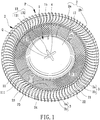
- FIG. 1 shows an impeller P according to a first embodiment of the invention.
- the impeller P includes a hub 1, a plurality of blades 2 coupled with the outer periphery of the hub 1, and at least two connecting rings 3 connected to the plurality of blades 2.
- the impeller P according to the invention can be used to form a centrifugal fan or a crossflow fan. The following description is made with the centrifugal fan, but it is not intended to limit the invention.
- a shaft 4 can be arranged at the center of the hub 1, which can be readily appreciated by one of ordinary skill and therefore it is not described herein for brevity.
- the hub 1 includes an annular wall 11 connected to the edge of a plate 12.
- the plate 12 has a central hole Q.
- the annular wall 11 can be coupled with the plurality of blades 2.
- the annular wall 11 includes an extension portion 111 that may be integrally formed with the annular wall 11.
- the extension portion 111 may be located between the at least two connecting rings 3 and the annular wall 11.
- the extension portion 111 is not connected to the at least two connecting rings 3 but extends radially outward from the annular wall 11 (away from the shaft 4) to connect with the plurality of blades 2.
- the extension portion 111 is made of plastic material and forms along the outer periphery of the annular wall 11.
- the extension portion 111 can increase the contact area between the plurality of blades 2 and the annular wall 11 of the hub 1.
- the plurality of blades 2 can be more securely coupled with the hub 1 without breaking easily.
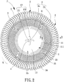
- the hub 1 has an inner face 1a (shown in FIG. 4 ) and an outer face 1b opposite to the inner face 1a.
- the hub 1 includes a reinforcing portion 13 around the central hole Q.
- the reinforcing portion 13 is configured to improve the structural strength of the hub 1.
- the reinforcing portion 13 provided on the inner face 1a of the hub 1 for illustration purpose.
- the reinforcing portion 13 includes an annular rib 131 around the central hole Q.
- the annular rib 131 can increase the structural strength of the plate 12 around the central hole Q.
- the reinforcing portion 13 can further include a plurality of protruding ribs 132 connecting to the annular rib 131 and extending towards the annular wall 11. As a preferred case of this arrangement, the plurality of protruding ribs 132 extends radially from the central hole Q, further improving the structural strength of the hub 1.
- the plurality of blades 2 preferably does not extend beyond the top face of the hub 1 to reduce the thickness of the impeller P.
- Each of the plurality of blades 2 includes a first end 2a connected to the extension portion 111 of the annular wall 11, as well as a second end 2b opposite to the first end 2a and having a height L1 larger than a height L2 of the first end 2a.
- the material of the plurality of blades 2 is not limited.
- Each of the plurality of blades 2 can be connected to the annular wall 11 by ways of fastening, adhesion or integral formation, which is not taken in a limited sense in the invention.
- the annular wall 11 and the plurality of blades 2 are made of the same material, integral formation can be used to improve the structural strength and production efficiency.
- the annular wall 11, the plurality of blades 2 and the at least two connecting rings 3 are made of polymer and are connected to the hub 1 by injection molding.
- the polymer is preferably the mixture of liquid crystal polymer and carbon fiber, the mixture of liquid crystal polymer and mineral fiber, or the mixture of liquid crystal polymer, glass fiber and mineral fiber.
- the metal powder of iron, aluminum, copper or alloy can be mixed with polymer adhesive to form the impeller P through injection molding of the mixture. This approach also improves the structural strength of the impeller P.
- each of the plurality of blades 2 has a top edge 21 and a bottom edge 22 opposite to the top edge 21.
- the distance between the top edge 21 and the bottom edge 22 gradually increases from the first end 2a to the second end 2b as shown in FIG. 3 , enabling the plurality of blades 2 to drive a larger volume of air.
- the height L2 of the second end 2b of the blade 2 may be 1-6 mm, and is preferably 1.7-4.7 mm.
- the thickness of the blade 2 may be 0.02-0.5 mm, with 0.1 mm preferred. This remains the fan in a slim fashion and prevents the overweighting of the impeller P, advantageously improving the operational efficiency thereof.
- the quantity of the plurality of blades 2 can be 70-134, and is preferably 91-134.
- the outer diameter of the impeller P can be larger than or equal to 40 mm, such that the slim blades 2 can drive air of sufficient volume and can be disposed around the hub 1.
- the connecting ring 3 has a thickness T1 which is preferably larger than or equal to the maximum thickness T2 of the blade 2 and is smaller than a quarter of the maximum height H of the blade 2 connecting to the connecting ring 3. Furthermore, the radial width B of the connecting ring 3 is preferably larger than or equal to the maximum thickness T2 of the blade 2, and is smaller than or equal to one sixth of the length L3 of the blade 2. In this arrangement, it can be ensured that the connecting ring 3 has a sufficient strength to reinforce the plurality of blades 2, thereby improving the stability of the plurality of blades 2.
- the first end 2a and the second end 2b of the blade 2 can align with each other in the same radial direction.
- the line passing through the first end 2a and the second end 2b of the blade 2 can pass through the center of the hub 1, such that the plurality of blades 2 can be connected to the hub 1 in a radial fashion.
- the line passing through the first end 2a and the second end 2b of the blade 2 does not pass through the center of the hub 1, such that each of the plurality of blades 2 is tangential to the annular wall 11 of the hub 1.
- the invention is limited to either implementation.
- each of the plurality of blades 2 includes a rear curving section 23 relatively adjacent to the hub 1, as well as a front curving section 24 relatively distant to the hub 1.
- the front curving section 24 curves in the same direction as the rotating direction K of the impeller P, whereas the rear curving section 23 curves in the opposite direction to the rotating direction K of the impeller P.
- Both the rear curving section 23 and the front curving section 24 can be in an arched form as shown in the drawing.
- Each of the plurality of blades 2 may further include an intermediate section 25 connected between the rear curving section 23 and the front curving section 24.
- the at least two connecting rings 3 are connected to any portions of the blade 2 between the first end 2a and the second end 2b, but are not connected to the extension portion 111.
- one of the at least two connecting rings 3 is connected to the middle of the blade 2 half of the length L3 from either end of the blade 2, or is connected to the rear curving section 23 or the front curving section 24.
- each of the at least two connecting rings 3 is connected to the blade 2 at any position from the second end 2b to where it is at one-third of the length L3 from the annular wall 11.
- one of the at least two connecting rings 3 is connected to the blade 2 at any position from the second end 2b to where it is at one-third of the length L3 from the annular wall 11, and the other connecting ring 3 is directly connected to the intermediate section 25 to better reinforce the plurality of blades 2.
- the stability of the plurality of blades 2 is improved, and therefore the vibration of the plurality of blades 2 under high-speed rotation is reduced.
- each of the at least two connecting rings 3 includes a first face 3a and a second face 3b opposite to the first face 3a.
- the first face 3a faces the top edge 21 of the blade 2 and the second face 3b faces the bottom edge 22 of the blade 2.
- At least one of the at least two connecting rings 3 is connected between the top edges 21 and the bottom edges 22 of the blade 2.
- the first face 3a of said at least one connecting ring 3 is not connected to the top edges 21 of the blades 2
- the second face 3b of said at least one connecting ring 3 is not connected to the bottom edges 22 of the blades 2.
- the at least two connecting rings 3 including two connecting rings 3 one of the two connecting rings 3 is disposed between but not connected to the top edges 21 and the bottom edges 22 of the blades 2, and another of the two connecting rings 3 is disposed on any other portion of the blade 2 such as the top edges 21 or the bottom edges 22 of the blades 2 (not limited).
- both the two connecting rings 3 are disposed between but not connected to the top edges 21 and the bottom edges 22 of the blades 2 to enhance the stability of the blades 2.
- the two connecting rings 3 are in the same level as shown in FIG. 3 .
- each connecting ring 3 is equally spaced from the top edge 21 as the second face 3b is spaced from the bottom edge 22, such that each connecting ring 3 is disposed in the middle of the blade 2 having an equal distance from the top edge 21 and the bottom edge 22 of the blade 2.
- a better reinforcement effect can be provided to improve the stability of the plurality of blades 2, further securing the plurality of blades 2 and reducing the vibration of the plurality of blades 2 under high-speed rotation.
- a cooling fan having the impeller P includes a fan frame 5.
- the fan frame 5 includes a base 51 having a shaft tube 52 into which the shaft 4, that is connected to the impeller P, is inserted.
- a stator 6 is fit around the outer periphery of the shaft tube 52. Since the two connecting rings 3 are connected between the top edges 21 and the bottom edges 22 of the plurality of blades 2 without having their first faces 3a connected to the top edges 21 and having their second faces 3b connected to the bottom edges 22, the two connecting rings 3 will have a sufficient strength to secure the plurality of blades 2 in place. This reduces the vibration or deformation of the impeller P caused by the blades 2 suffering from the impact of the air resistance, thus improving the overall stability of the blades 2 including its rotational stability and advantageously reducing the noise.
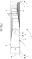
- FIG. 5a showing an impeller P according to a second embodiment of the invention.
- One of the two connecting rings 3 is disposed between but not connected to the top edges 21 and the bottom edges 22 of the plurality of blades 2 and is relatively adjacent to the hub 1, whereas the other connecting ring 3 is relatively distant to the hub 1 and is disposed at the second ends 2b of the plurality of blades 2 and is connected to the bottom edges 22 of the plurality of blades 2.
- the other connecting ring 3 can be connected to the plurality of blades 2 slightly above or below the bottom edges 22 of the plurality of blades 2 as shown in FIG. 5a .
- the other connecting ring 3 can be flush with the bottom edges 22 of the plurality of blades 2 without protruding beyond said bottom edges 22 , or can partially or completely protrude beyond the bottom edges 22 of the plurality of blades 2.
- the other connecting ring 3 is flush with the bottom edges 22 of the plurality of blades 2 without protruding beyond said bottom edges 22; namely, the second face 3b of the other connecting ring 3 is connected to the bottom edges 22 of the plurality of blades 2 as an alternative arrangement of the impeller P.
- the other connecting ring 3 can also be connected to the plurality of blades 2 slightly above or below the top edges 21 of the plurality of blades 2.
- the other connecting ring 3 can be flush with the top edges 21 of the plurality of blades 2 without protruding beyond said top edges 21, or can partially or completely protrude beyond the top edges 21 of the plurality of blades 2.
- the other connecting ring 3 can extend completely beyond the top edges 21 of the plurality of blades 2 as shown in FIG. 5b ; namely, the second face 3b of the other connecting ring 3 is connected to the top edges 21 of the plurality of blades 2 in a manner that the second face 3b of the other connecting ring 3 is flush with the top edges 21 of the plurality of blades 2. This provides another alternative arrangement of the impeller P.
- One of the two connecting rings 3 is disposed between but not connected to the top edges 21 and the bottom edges 22 of the plurality of blades 2 and is relatively distant to the hub 1 and is disposed at the second ends 2b of the plurality of blades 2, whereas the other connecting ring 3 is relatively adjacent to the hub 1 and is connected to the plurality of blades 2 slightly above or below the top edges 21 of the plurality of blades 2.
- the other connecting ring 3 can be flush with the top edges 21 of the plurality of blades 2 without protruding beyond said top edges 21, or can partially or completely protrude beyond the top edges 21 of the plurality of blades 2.
- the other connecting ring 3 is flush with the top edges 21 of the plurality of blades 2 without protruding beyond said top edges 21; namely, the first face 3a of the other connecting ring 3 is connected to the top edges 21 of the plurality of blades 2, ensuring that the other connecting ring 3 has larger contact areas with the plurality of blades 2. This reduces the vibration of the blades 2 resulting from the air resistance, thus providing a further alternative arrangement of the impeller P.
- FIG. 7 showing an impeller P according to a fourth embodiment of the invention where the quantity of the at least two connecting rings 3 is three.
- One of the three connecting rings 3 is disposed between but not connected to the top edges 21 and the bottom edges 22 of the plurality of blades 2 and is relatively adjacent to the hub 1, whereas the other two connecting rings 3 are relatively distant to the hub 1 and are preferably staggered and are respectively connected to top edges 21 and the bottom edges 22 of the plurality of blades 2.
- one connecting ring 3 can be connected to the plurality of blades 2 slightly above or below the top edges 21 of the plurality of blades 2, and the other connecting ring 3 can be connected to the plurality of blades 2 slightly above or below the bottom edges 22 of the plurality of blades 2 as shown in FIG. 7 .
- one connecting ring 3 can be flush with the top edges 21 of the plurality of blades 2 without protruding beyond said top edges 21, or can partially or completely protrude beyond the top edges 21 of the plurality of blades 2.
- the other connecting ring 3 can be flush with the bottom edges 22 of the plurality of blades 2 without protruding beyond said bottom edges 22, or can partially or completely protrude beyond the bottom edges 22 of the plurality of blades 2.
- one connecting ring 3 among the other two connecting rings 3 completely protrudes beyond the top edges 21 of the plurality of blades 2, and the other connecting ring 3 is flush with the bottom edges 22 of the plurality of blades 2 without protruding beyond said bottom edges 22 to thereby reduce the height of the impeller.
- FIG. 8 shows three sets of air volume test results of the cooling fan under 1 atm for different arrangements of the two connecting rings 3 of the impeller P according to the invention.
- the first set of test result is obtained by having both the connecting rings 3 disposed at the top edges 21 of the plurality of blades 2 (a conventional arrangement not described in the background art).
- the second set of test result is obtained by having one of the two connecting rings 3, which is relatively adjacent to the hub 1, disposed between the top edges 21 and the bottom edges 22 of the plurality of blades 2, as well as having the other connecting ring 3, which is relatively distant to the hub 1, disposed at the top edges 21 of the plurality of blades 2, as is described in the second embodiment of the invention.
- the third set of test result is obtained by having both the connecting rings 3 disposed between the top edges 21 and the bottom edges 22 of the plurality of blades 2, as is described in the first embodiment of the invention.
- the at least two connecting rings can have a sufficient strength by having one or more of the at least two connecting rings disposed between but not connected to the top edges and the bottom edges of the plurality of blades.
- the plurality of blades can be retained in place to reduce the vibration or deformation of the impeller caused by the plurality of blades suffering from the impact of the air resistance.
- the rotational stability of the plurality of blades and the performance of the cooling fan can be improved and the noise can be reduced.
Landscapes
- Engineering & Computer Science (AREA)
- Mechanical Engineering (AREA)
- General Engineering & Computer Science (AREA)
- Structures Of Non-Positive Displacement Pumps (AREA)
Applications Claiming Priority (1)
| Application Number | Priority Date | Filing Date | Title |
|---|---|---|---|
| TW108147421A TWI725683B (zh) | 2019-12-24 | 2019-12-24 | 扇輪及具有該扇輪之散熱風扇 |
Publications (3)
| Publication Number | Publication Date |
|---|---|
| EP3842643A1 true EP3842643A1 (fr) | 2021-06-30 |
| EP3842643B1 EP3842643B1 (fr) | 2024-05-01 |
| EP3842643C0 EP3842643C0 (fr) | 2024-05-01 |
Family
ID=69845948
Family Applications (1)
| Application Number | Title | Priority Date | Filing Date |
|---|---|---|---|
| EP20163936.6A Active EP3842643B1 (fr) | 2019-12-24 | 2020-03-18 | Rotor et ventilateur de refroidissement comprenant le rotor |
Country Status (6)
| Country | Link |
|---|---|
| US (1) | US11286947B2 (fr) |
| EP (1) | EP3842643B1 (fr) |
| JP (1) | JP7112442B2 (fr) |
| KR (1) | KR102398254B1 (fr) |
| CN (2) | CN113027813B (fr) |
| TW (1) | TWI725683B (fr) |
Families Citing this family (12)
| Publication number | Priority date | Publication date | Assignee | Title |
|---|---|---|---|---|
| TWI725683B (zh) * | 2019-12-24 | 2021-04-21 | 建準電機工業股份有限公司 | 扇輪及具有該扇輪之散熱風扇 |
| US11536286B2 (en) * | 2020-07-30 | 2022-12-27 | Microsoft Technology Licensing, Llc | Systems and methods for improving airflow in a centrifugal blower |
| TWD217630S (zh) * | 2021-05-27 | 2022-03-11 | 台達電子工業股份有限公司 | 扇葉之部分 |
| USD1089621S1 (en) * | 2021-10-29 | 2025-08-19 | Delta Electronics, Inc. | Fan blade |
| USD1099287S1 (en) * | 2021-10-29 | 2025-10-21 | Delta Electronics, Inc. | Fan blade |
| CN217080873U (zh) * | 2022-03-04 | 2022-07-29 | 台达电子工业股份有限公司 | 叶轮 |
| CN117469185A (zh) * | 2022-07-22 | 2024-01-30 | 台达电子工业股份有限公司 | 散热组装结构 |
| USD1063054S1 (en) * | 2022-08-03 | 2025-02-18 | Delta Electronics, Inc. | Fan blade |
| USD1063056S1 (en) * | 2022-08-03 | 2025-02-18 | Delta Electronics, Inc. | Fan blade |
| USD1063055S1 (en) * | 2022-08-03 | 2025-02-18 | Delta Electronics, Inc. | Fan blade |
| TWI847283B (zh) * | 2022-09-26 | 2024-07-01 | 華碩電腦股份有限公司 | 風扇模組 |
| CN222376766U (zh) * | 2024-05-21 | 2025-01-21 | 南昌华勤电子科技有限公司 | 风扇转子、散热风扇及电子设备 |
Citations (6)
| Publication number | Priority date | Publication date | Assignee | Title |
|---|---|---|---|---|
| TW200903233A (en) * | 2007-07-13 | 2009-01-16 | Foxconn Tech Co Ltd | Fan impeller |
| GB2478646A (en) * | 2010-03-09 | 2011-09-14 | Bosch Gmbh Robert | Fan blade spacing and/or construction |
| US20150152883A1 (en) * | 2013-12-04 | 2015-06-04 | Apple Inc. | Shrouded fan impeller with reduced cover overlap |
| TWM516103U (zh) | 2015-11-03 | 2016-01-21 | Forcecon Technology Co Ltd | 離心式散熱風扇之扇輪 |
| US20160290355A1 (en) * | 2015-03-31 | 2016-10-06 | Cooler Master Co., Ltd. | Fan impeller |
| CN209569198U (zh) * | 2018-11-16 | 2019-11-01 | 昆山广兴电子有限公司 | 风扇的扇轮 |
Family Cites Families (31)
| Publication number | Priority date | Publication date | Assignee | Title |
|---|---|---|---|---|
| JPH08326696A (ja) * | 1995-05-30 | 1996-12-10 | Toshiba Corp | 送風機用羽根 |
| JPH09222095A (ja) * | 1995-12-13 | 1997-08-26 | Toto Ltd | 送風機 |
| US5829956A (en) * | 1997-04-22 | 1998-11-03 | Chen; Yung | Fan blade assembly |
| US20030012653A1 (en) * | 2001-07-13 | 2003-01-16 | Guy Diemunsch | Cooling fan |
| US7722311B2 (en) * | 2006-01-11 | 2010-05-25 | Borgwarner Inc. | Pressure and current reducing impeller |
| JP2008215150A (ja) * | 2007-03-02 | 2008-09-18 | Nippon Densan Corp | 軸流ファンモータ |
| CN101358607A (zh) * | 2007-08-03 | 2009-02-04 | 富准精密工业(深圳)有限公司 | 扇叶结构 |
| JP5422139B2 (ja) * | 2008-04-18 | 2014-02-19 | 三菱重工業株式会社 | プロペラファン |
| KR20100123055A (ko) * | 2009-05-14 | 2010-11-24 | 한국델파이주식회사 | 축류팬 |
| JP2012180810A (ja) | 2011-03-02 | 2012-09-20 | Toshiba Home Technology Corp | 送風装置 |
| TWI453346B (zh) | 2011-04-25 | 2014-09-21 | Sunonwealth Electr Mach Ind Co | 散熱扇 |
| CN103807208B (zh) * | 2012-11-08 | 2016-04-27 | 英业达科技有限公司 | 扇叶结构 |
| DE102013213815A1 (de) * | 2013-07-15 | 2015-01-15 | Pfeiffer Vacuum Gmbh | Vakuumpumpe |
| CN105626585B (zh) * | 2014-10-11 | 2019-11-01 | 雷勃美国公司 | 冷却马达的风扇和方法 |
| TWI601884B (zh) * | 2016-02-22 | 2017-10-11 | 佛山市建準電子有限公司 | 可調整配重之扇輪及風扇 |
| WO2017192647A1 (fr) * | 2016-05-03 | 2017-11-09 | Carrier Corporation | Entrée pour ventilateur axial |
| CN205805945U (zh) * | 2016-06-30 | 2016-12-14 | 东莞动利电子有限公司 | 一种多圈动叶式离心扇 |
| TWI597109B (zh) | 2016-10-25 | 2017-09-01 | 廣達電腦股份有限公司 | 風扇結構及其製造方法 |
| GB2557679A (en) | 2016-12-15 | 2018-06-27 | Edwards Ltd | Stator blade unit for a turbomolecular pump |
| US10677258B2 (en) * | 2017-01-19 | 2020-06-09 | Nidec Corporation | Blower comprising impeller and motor |
| JP6827331B2 (ja) * | 2017-01-30 | 2021-02-10 | シナノケンシ株式会社 | アウターロータ型モータ |
| CN206617363U (zh) * | 2017-03-01 | 2017-11-07 | 讯凯国际股份有限公司 | 叶轮 |
| CN107288924A (zh) * | 2017-08-17 | 2017-10-24 | 联想(北京)有限公司 | 一种电子设备及其散热风扇 |
| TWI658214B (zh) * | 2017-08-25 | 2019-05-01 | 宏碁股份有限公司 | 散熱扇葉與散熱風扇 |
| CN109707647B (zh) * | 2017-10-26 | 2021-09-03 | 台达电子工业股份有限公司 | 风扇 |
| TW201925632A (zh) * | 2017-11-24 | 2019-07-01 | 和碩聯合科技股份有限公司 | 葉輪、風扇及扇葉片製作方法 |
| CN108194394A (zh) | 2018-02-07 | 2018-06-22 | 广东美的环境电器制造有限公司 | 风扇的前网罩和具有其的风扇 |
| CN208185055U (zh) | 2018-05-23 | 2018-12-04 | 奇鋐科技股份有限公司 | 扇轮结构 |
| CN108612671B (zh) * | 2018-05-23 | 2020-11-20 | 奇鋐科技股份有限公司 | 扇轮结构 |
| US10989218B2 (en) * | 2018-05-29 | 2021-04-27 | Asia Vital Components Co., Ltd. | Fan wheel structure |
| TWI725683B (zh) * | 2019-12-24 | 2021-04-21 | 建準電機工業股份有限公司 | 扇輪及具有該扇輪之散熱風扇 |
-
2019
- 2019-12-24 TW TW108147421A patent/TWI725683B/zh active
- 2019-12-31 CN CN201911409998.XA patent/CN113027813B/zh active Active
- 2019-12-31 CN CN201922482724.5U patent/CN212407116U/zh not_active Expired - Fee Related
-
2020
- 2020-02-13 KR KR1020200017370A patent/KR102398254B1/ko active Active
- 2020-02-14 JP JP2020023600A patent/JP7112442B2/ja active Active
- 2020-02-26 US US16/801,405 patent/US11286947B2/en active Active
- 2020-03-18 EP EP20163936.6A patent/EP3842643B1/fr active Active
Patent Citations (6)
| Publication number | Priority date | Publication date | Assignee | Title |
|---|---|---|---|---|
| TW200903233A (en) * | 2007-07-13 | 2009-01-16 | Foxconn Tech Co Ltd | Fan impeller |
| GB2478646A (en) * | 2010-03-09 | 2011-09-14 | Bosch Gmbh Robert | Fan blade spacing and/or construction |
| US20150152883A1 (en) * | 2013-12-04 | 2015-06-04 | Apple Inc. | Shrouded fan impeller with reduced cover overlap |
| US20160290355A1 (en) * | 2015-03-31 | 2016-10-06 | Cooler Master Co., Ltd. | Fan impeller |
| TWM516103U (zh) | 2015-11-03 | 2016-01-21 | Forcecon Technology Co Ltd | 離心式散熱風扇之扇輪 |
| CN209569198U (zh) * | 2018-11-16 | 2019-11-01 | 昆山广兴电子有限公司 | 风扇的扇轮 |
Also Published As
| Publication number | Publication date |
|---|---|
| US11286947B2 (en) | 2022-03-29 |
| CN212407116U (zh) | 2021-01-26 |
| JP2021102956A (ja) | 2021-07-15 |
| EP3842643B1 (fr) | 2024-05-01 |
| KR20210082334A (ko) | 2021-07-05 |
| JP7112442B2 (ja) | 2022-08-03 |
| CN113027813A (zh) | 2021-06-25 |
| TWI725683B (zh) | 2021-04-21 |
| EP3842643C0 (fr) | 2024-05-01 |
| CN113027813B (zh) | 2023-09-15 |
| US20210190089A1 (en) | 2021-06-24 |
| KR102398254B1 (ko) | 2022-05-13 |
| TW202124851A (zh) | 2021-07-01 |
Similar Documents
| Publication | Publication Date | Title |
|---|---|---|
| US11286947B2 (en) | Impeller and cooling fan including the impeller | |
| US11401943B2 (en) | Impeller with reinforced blades | |
| US8257043B2 (en) | Multiblade impeller | |
| US6572333B2 (en) | Air blower | |
| US7329091B2 (en) | Heat dissipation fans and housings therefor | |
| JP6063619B2 (ja) | 遠心式ファン | |
| US20080075598A1 (en) | Fan assembly and impeller thereof | |
| US9964119B2 (en) | Centrifugal fan | |
| US9169844B2 (en) | Centrifugal fan and impeller thereof | |
| US9234528B2 (en) | Motor base | |
| CN211924557U (zh) | 扇轮及具有该扇轮的散热风扇 | |
| US7614851B2 (en) | Centrifugal fans and impellers thereof | |
| CN114738315A (zh) | 风扇叶轮 | |
| US11578731B2 (en) | Asymmetrical double-outlet blower | |
| US6844641B1 (en) | Casing for heat-dissipating fan | |
| US7884513B2 (en) | Rotor | |
| US8282347B2 (en) | Impeller and centrifugal pump including the same | |
| TWI670421B (zh) | 扇輪 | |
| CN112240312A (zh) | 扇轮 | |
| KR20090002529A (ko) | 진동저감 및 흡입효과가 개선된 임펠러 구조 | |
| CN100451344C (zh) | 离心式风扇及其叶轮 | |
| KR20240009118A (ko) | 시로코팬 |
Legal Events
| Date | Code | Title | Description |
|---|---|---|---|
| PUAI | Public reference made under article 153(3) epc to a published international application that has entered the european phase |
Free format text: ORIGINAL CODE: 0009012 |
|
| STAA | Information on the status of an ep patent application or granted ep patent |
Free format text: STATUS: REQUEST FOR EXAMINATION WAS MADE |
|
| 17P | Request for examination filed |
Effective date: 20210209 |
|
| AK | Designated contracting states |
Kind code of ref document: A1 Designated state(s): AL AT BE BG CH CY CZ DE DK EE ES FI FR GB GR HR HU IE IS IT LI LT LU LV MC MK MT NL NO PL PT RO RS SE SI SK SM TR |
|
| RIC1 | Information provided on ipc code assigned before grant |
Ipc: F04D 29/66 20060101ALI20220503BHEP Ipc: F04D 29/30 20060101ALI20220503BHEP Ipc: F04D 29/28 20060101AFI20220503BHEP |
|
| STAA | Information on the status of an ep patent application or granted ep patent |
Free format text: STATUS: EXAMINATION IS IN PROGRESS |
|
| 17Q | First examination report despatched |
Effective date: 20220615 |
|
| GRAP | Despatch of communication of intention to grant a patent |
Free format text: ORIGINAL CODE: EPIDOSNIGR1 |
|
| STAA | Information on the status of an ep patent application or granted ep patent |
Free format text: STATUS: GRANT OF PATENT IS INTENDED |
|
| INTG | Intention to grant announced |
Effective date: 20231218 |
|
| GRAS | Grant fee paid |
Free format text: ORIGINAL CODE: EPIDOSNIGR3 |
|
| GRAA | (expected) grant |
Free format text: ORIGINAL CODE: 0009210 |
|
| STAA | Information on the status of an ep patent application or granted ep patent |
Free format text: STATUS: THE PATENT HAS BEEN GRANTED |
|
| AK | Designated contracting states |
Kind code of ref document: B1 Designated state(s): AL AT BE BG CH CY CZ DE DK EE ES FI FR GB GR HR HU IE IS IT LI LT LU LV MC MK MT NL NO PL PT RO RS SE SI SK SM TR |
|
| REG | Reference to a national code |
Ref country code: GB Ref legal event code: FG4D |
|
| REG | Reference to a national code |
Ref country code: CH Ref legal event code: EP |
|
| REG | Reference to a national code |
Ref country code: IE Ref legal event code: FG4D |
|
| REG | Reference to a national code |
Ref country code: DE Ref legal event code: R096 Ref document number: 602020029907 Country of ref document: DE |
|
| U01 | Request for unitary effect filed |
Effective date: 20240517 |
|
| U07 | Unitary effect registered |
Designated state(s): AT BE BG DE DK EE FI FR IT LT LU LV MT NL PT SE SI Effective date: 20240529 |
|
| PG25 | Lapsed in a contracting state [announced via postgrant information from national office to epo] |
Ref country code: IS Free format text: LAPSE BECAUSE OF FAILURE TO SUBMIT A TRANSLATION OF THE DESCRIPTION OR TO PAY THE FEE WITHIN THE PRESCRIBED TIME-LIMIT Effective date: 20240901 |
|
| PG25 | Lapsed in a contracting state [announced via postgrant information from national office to epo] |
Ref country code: HR Free format text: LAPSE BECAUSE OF FAILURE TO SUBMIT A TRANSLATION OF THE DESCRIPTION OR TO PAY THE FEE WITHIN THE PRESCRIBED TIME-LIMIT Effective date: 20240501 |
|
| PG25 | Lapsed in a contracting state [announced via postgrant information from national office to epo] |
Ref country code: GR Free format text: LAPSE BECAUSE OF FAILURE TO SUBMIT A TRANSLATION OF THE DESCRIPTION OR TO PAY THE FEE WITHIN THE PRESCRIBED TIME-LIMIT Effective date: 20240802 |
|
| PG25 | Lapsed in a contracting state [announced via postgrant information from national office to epo] |
Ref country code: ES Free format text: LAPSE BECAUSE OF FAILURE TO SUBMIT A TRANSLATION OF THE DESCRIPTION OR TO PAY THE FEE WITHIN THE PRESCRIBED TIME-LIMIT Effective date: 20240501 |
|
| PG25 | Lapsed in a contracting state [announced via postgrant information from national office to epo] |
Ref country code: PL Free format text: LAPSE BECAUSE OF FAILURE TO SUBMIT A TRANSLATION OF THE DESCRIPTION OR TO PAY THE FEE WITHIN THE PRESCRIBED TIME-LIMIT Effective date: 20240501 |
|
| PG25 | Lapsed in a contracting state [announced via postgrant information from national office to epo] |
Ref country code: PL Free format text: LAPSE BECAUSE OF FAILURE TO SUBMIT A TRANSLATION OF THE DESCRIPTION OR TO PAY THE FEE WITHIN THE PRESCRIBED TIME-LIMIT Effective date: 20240501 Ref country code: NO Free format text: LAPSE BECAUSE OF FAILURE TO SUBMIT A TRANSLATION OF THE DESCRIPTION OR TO PAY THE FEE WITHIN THE PRESCRIBED TIME-LIMIT Effective date: 20240801 Ref country code: IS Free format text: LAPSE BECAUSE OF FAILURE TO SUBMIT A TRANSLATION OF THE DESCRIPTION OR TO PAY THE FEE WITHIN THE PRESCRIBED TIME-LIMIT Effective date: 20240901 Ref country code: HR Free format text: LAPSE BECAUSE OF FAILURE TO SUBMIT A TRANSLATION OF THE DESCRIPTION OR TO PAY THE FEE WITHIN THE PRESCRIBED TIME-LIMIT Effective date: 20240501 Ref country code: GR Free format text: LAPSE BECAUSE OF FAILURE TO SUBMIT A TRANSLATION OF THE DESCRIPTION OR TO PAY THE FEE WITHIN THE PRESCRIBED TIME-LIMIT Effective date: 20240802 Ref country code: ES Free format text: LAPSE BECAUSE OF FAILURE TO SUBMIT A TRANSLATION OF THE DESCRIPTION OR TO PAY THE FEE WITHIN THE PRESCRIBED TIME-LIMIT Effective date: 20240501 Ref country code: RS Free format text: LAPSE BECAUSE OF FAILURE TO SUBMIT A TRANSLATION OF THE DESCRIPTION OR TO PAY THE FEE WITHIN THE PRESCRIBED TIME-LIMIT Effective date: 20240801 |
|
| PG25 | Lapsed in a contracting state [announced via postgrant information from national office to epo] |
Ref country code: CZ Free format text: LAPSE BECAUSE OF FAILURE TO SUBMIT A TRANSLATION OF THE DESCRIPTION OR TO PAY THE FEE WITHIN THE PRESCRIBED TIME-LIMIT Effective date: 20240501 |
|
| PG25 | Lapsed in a contracting state [announced via postgrant information from national office to epo] |
Ref country code: SK Free format text: LAPSE BECAUSE OF FAILURE TO SUBMIT A TRANSLATION OF THE DESCRIPTION OR TO PAY THE FEE WITHIN THE PRESCRIBED TIME-LIMIT Effective date: 20240501 Ref country code: RO Free format text: LAPSE BECAUSE OF FAILURE TO SUBMIT A TRANSLATION OF THE DESCRIPTION OR TO PAY THE FEE WITHIN THE PRESCRIBED TIME-LIMIT Effective date: 20240501 |
|
| PG25 | Lapsed in a contracting state [announced via postgrant information from national office to epo] |
Ref country code: SM Free format text: LAPSE BECAUSE OF FAILURE TO SUBMIT A TRANSLATION OF THE DESCRIPTION OR TO PAY THE FEE WITHIN THE PRESCRIBED TIME-LIMIT Effective date: 20240501 |
|
| PG25 | Lapsed in a contracting state [announced via postgrant information from national office to epo] |
Ref country code: SM Free format text: LAPSE BECAUSE OF FAILURE TO SUBMIT A TRANSLATION OF THE DESCRIPTION OR TO PAY THE FEE WITHIN THE PRESCRIBED TIME-LIMIT Effective date: 20240501 Ref country code: SK Free format text: LAPSE BECAUSE OF FAILURE TO SUBMIT A TRANSLATION OF THE DESCRIPTION OR TO PAY THE FEE WITHIN THE PRESCRIBED TIME-LIMIT Effective date: 20240501 Ref country code: RO Free format text: LAPSE BECAUSE OF FAILURE TO SUBMIT A TRANSLATION OF THE DESCRIPTION OR TO PAY THE FEE WITHIN THE PRESCRIBED TIME-LIMIT Effective date: 20240501 Ref country code: CZ Free format text: LAPSE BECAUSE OF FAILURE TO SUBMIT A TRANSLATION OF THE DESCRIPTION OR TO PAY THE FEE WITHIN THE PRESCRIBED TIME-LIMIT Effective date: 20240501 |
|
| REG | Reference to a national code |
Ref country code: DE Ref legal event code: R097 Ref document number: 602020029907 Country of ref document: DE |
|
| PLBE | No opposition filed within time limit |
Free format text: ORIGINAL CODE: 0009261 |
|
| STAA | Information on the status of an ep patent application or granted ep patent |
Free format text: STATUS: NO OPPOSITION FILED WITHIN TIME LIMIT |
|
| U20 | Renewal fee for the european patent with unitary effect paid |
Year of fee payment: 6 Effective date: 20250211 |
|
| 26N | No opposition filed |
Effective date: 20250204 |
|
| PG25 | Lapsed in a contracting state [announced via postgrant information from national office to epo] |
Ref country code: MC Free format text: LAPSE BECAUSE OF FAILURE TO SUBMIT A TRANSLATION OF THE DESCRIPTION OR TO PAY THE FEE WITHIN THE PRESCRIBED TIME-LIMIT Effective date: 20240501 |
|
| REG | Reference to a national code |
Ref country code: CH Ref legal event code: H13 Free format text: ST27 STATUS EVENT CODE: U-0-0-H10-H13 (AS PROVIDED BY THE NATIONAL OFFICE) Effective date: 20251023 |
|
| PG25 | Lapsed in a contracting state [announced via postgrant information from national office to epo] |
Ref country code: CH Free format text: LAPSE BECAUSE OF NON-PAYMENT OF DUE FEES Effective date: 20250331 |
|
| PG25 | Lapsed in a contracting state [announced via postgrant information from national office to epo] |
Ref country code: IE Free format text: LAPSE BECAUSE OF NON-PAYMENT OF DUE FEES Effective date: 20250318 |
|
| U20 | Renewal fee for the european patent with unitary effect paid |
Year of fee payment: 7 Effective date: 20260223 |
|
| PGFP | Annual fee paid to national office [announced via postgrant information from national office to epo] |
Ref country code: GB Payment date: 20260324 Year of fee payment: 7 |