EP3842671A1 - Wellendichtung, insbesondere radialwellendichtung, mit wenigstens einem dichtelement - Google Patents
Wellendichtung, insbesondere radialwellendichtung, mit wenigstens einem dichtelement Download PDFInfo
- Publication number
- EP3842671A1 EP3842671A1 EP20000490.1A EP20000490A EP3842671A1 EP 3842671 A1 EP3842671 A1 EP 3842671A1 EP 20000490 A EP20000490 A EP 20000490A EP 3842671 A1 EP3842671 A1 EP 3842671A1
- Authority
- EP
- European Patent Office
- Prior art keywords
- shaft seal
- sealing
- ring
- sealing element
- section
- Prior art date
- Legal status (The legal status is an assumption and is not a legal conclusion. Google has not performed a legal analysis and makes no representation as to the accuracy of the status listed.)
- Granted
Links
Images


Classifications
-
- F—MECHANICAL ENGINEERING; LIGHTING; HEATING; WEAPONS; BLASTING
- F16—ENGINEERING ELEMENTS AND UNITS; GENERAL MEASURES FOR PRODUCING AND MAINTAINING EFFECTIVE FUNCTIONING OF MACHINES OR INSTALLATIONS; THERMAL INSULATION IN GENERAL
- F16J—PISTONS; CYLINDERS; SEALINGS
- F16J15/00—Sealings
- F16J15/16—Sealings between relatively-moving surfaces
- F16J15/32—Sealings between relatively-moving surfaces with elastic sealings, e.g. O-rings
- F16J15/3204—Sealings between relatively-moving surfaces with elastic sealings, e.g. O-rings with at least one lip
- F16J15/3228—Sealings between relatively-moving surfaces with elastic sealings, e.g. O-rings with at least one lip formed by deforming a flat ring
-
- F—MECHANICAL ENGINEERING; LIGHTING; HEATING; WEAPONS; BLASTING
- F16—ENGINEERING ELEMENTS AND UNITS; GENERAL MEASURES FOR PRODUCING AND MAINTAINING EFFECTIVE FUNCTIONING OF MACHINES OR INSTALLATIONS; THERMAL INSULATION IN GENERAL
- F16J—PISTONS; CYLINDERS; SEALINGS
- F16J15/00—Sealings
- F16J15/16—Sealings between relatively-moving surfaces
- F16J15/32—Sealings between relatively-moving surfaces with elastic sealings, e.g. O-rings
- F16J15/3204—Sealings between relatively-moving surfaces with elastic sealings, e.g. O-rings with at least one lip
- F16J15/3208—Sealings between relatively-moving surfaces with elastic sealings, e.g. O-rings with at least one lip provided with tension elements, e.g. elastic rings
-
- F—MECHANICAL ENGINEERING; LIGHTING; HEATING; WEAPONS; BLASTING
- F16—ENGINEERING ELEMENTS AND UNITS; GENERAL MEASURES FOR PRODUCING AND MAINTAINING EFFECTIVE FUNCTIONING OF MACHINES OR INSTALLATIONS; THERMAL INSULATION IN GENERAL
- F16J—PISTONS; CYLINDERS; SEALINGS
- F16J15/00—Sealings
- F16J15/16—Sealings between relatively-moving surfaces
- F16J15/32—Sealings between relatively-moving surfaces with elastic sealings, e.g. O-rings
- F16J15/3204—Sealings between relatively-moving surfaces with elastic sealings, e.g. O-rings with at least one lip
- F16J15/3232—Sealings between relatively-moving surfaces with elastic sealings, e.g. O-rings with at least one lip having two or more lips
-
- F—MECHANICAL ENGINEERING; LIGHTING; HEATING; WEAPONS; BLASTING
- F16—ENGINEERING ELEMENTS AND UNITS; GENERAL MEASURES FOR PRODUCING AND MAINTAINING EFFECTIVE FUNCTIONING OF MACHINES OR INSTALLATIONS; THERMAL INSULATION IN GENERAL
- F16J—PISTONS; CYLINDERS; SEALINGS
- F16J15/00—Sealings
- F16J15/16—Sealings between relatively-moving surfaces
- F16J15/32—Sealings between relatively-moving surfaces with elastic sealings, e.g. O-rings
- F16J15/324—Arrangements for lubrication or cooling of the sealing itself
-
- F—MECHANICAL ENGINEERING; LIGHTING; HEATING; WEAPONS; BLASTING
- F16—ENGINEERING ELEMENTS AND UNITS; GENERAL MEASURES FOR PRODUCING AND MAINTAINING EFFECTIVE FUNCTIONING OF MACHINES OR INSTALLATIONS; THERMAL INSULATION IN GENERAL
- F16J—PISTONS; CYLINDERS; SEALINGS
- F16J15/00—Sealings
- F16J15/16—Sealings between relatively-moving surfaces
- F16J15/32—Sealings between relatively-moving surfaces with elastic sealings, e.g. O-rings
- F16J15/3248—Sealings between relatively-moving surfaces with elastic sealings, e.g. O-rings provided with casings or supports
- F16J15/3252—Sealings between relatively-moving surfaces with elastic sealings, e.g. O-rings provided with casings or supports with rigid casings or supports
-
- F—MECHANICAL ENGINEERING; LIGHTING; HEATING; WEAPONS; BLASTING
- F16—ENGINEERING ELEMENTS AND UNITS; GENERAL MEASURES FOR PRODUCING AND MAINTAINING EFFECTIVE FUNCTIONING OF MACHINES OR INSTALLATIONS; THERMAL INSULATION IN GENERAL
- F16J—PISTONS; CYLINDERS; SEALINGS
- F16J15/00—Sealings
- F16J15/16—Sealings between relatively-moving surfaces
- F16J15/32—Sealings between relatively-moving surfaces with elastic sealings, e.g. O-rings
- F16J15/3248—Sealings between relatively-moving surfaces with elastic sealings, e.g. O-rings provided with casings or supports
- F16J15/3252—Sealings between relatively-moving surfaces with elastic sealings, e.g. O-rings provided with casings or supports with rigid casings or supports
- F16J15/3256—Sealings between relatively-moving surfaces with elastic sealings, e.g. O-rings provided with casings or supports with rigid casings or supports comprising two casing or support elements, one attached to each surface, e.g. cartridge or cassette seals
-
- F—MECHANICAL ENGINEERING; LIGHTING; HEATING; WEAPONS; BLASTING
- F16—ENGINEERING ELEMENTS AND UNITS; GENERAL MEASURES FOR PRODUCING AND MAINTAINING EFFECTIVE FUNCTIONING OF MACHINES OR INSTALLATIONS; THERMAL INSULATION IN GENERAL
- F16J—PISTONS; CYLINDERS; SEALINGS
- F16J15/00—Sealings
- F16J15/16—Sealings between relatively-moving surfaces
- F16J15/32—Sealings between relatively-moving surfaces with elastic sealings, e.g. O-rings
- F16J15/3268—Mounting of sealing rings
-
- F—MECHANICAL ENGINEERING; LIGHTING; HEATING; WEAPONS; BLASTING
- F16—ENGINEERING ELEMENTS AND UNITS; GENERAL MEASURES FOR PRODUCING AND MAINTAINING EFFECTIVE FUNCTIONING OF MACHINES OR INSTALLATIONS; THERMAL INSULATION IN GENERAL
- F16J—PISTONS; CYLINDERS; SEALINGS
- F16J15/00—Sealings
- F16J15/16—Sealings between relatively-moving surfaces
- F16J15/32—Sealings between relatively-moving surfaces with elastic sealings, e.g. O-rings
- F16J15/3284—Sealings between relatively-moving surfaces with elastic sealings, e.g. O-rings characterised by their structure; Selection of materials
Definitions
- the invention relates to a shaft seal, in particular a radial shaft seal, according to the preamble of claim 1.
- polyfluorocarbon in particular polytetrafluoroethylene
- the sealing elements are designed as ring disks, the radially inner area of which is elastically bent to form the sealing lip.
- polyfluorocarbons especially polytetrafluoroethylene
- creep can be observed.
- these materials have a relatively low mechanical strength. The creeping of this material leads to the fact that the sealing effect diminishes. In order to counteract this creep effect, the radial preload that acts on the sealing lip is increased. However, this leads to a correspondingly greater wear on the sealing lip. Different fillers are therefore added to sealing elements, which complicate and make their production more expensive.
- the DE 10 2012 001 226 describes an alternative shaft seal, in particular a radial shaft seal, with at least one sealing element that is provided with a sealing lip that rests against a surface to be sealed under radial force, and with at least one elastomer element that loads the sealing lip in the direction of the surface to be sealed. Due to their cross-section, suitable elastomer elements can only be manufactured at high cost.
- the invention is based on the object of designing the generic shaft seal in such a way that it is simpler and more cost-effective to manufacture.
- the shaft seal comprises an elastomer element that supports the sealing element.
- a sealing ring is used as the elastomer element.
- the sealing ring supports the sealing element in such a way that the sealing lip, which effects the dynamic sealing towards the shaft, is pressed in the direction of the surface to be sealed.
- the sealing lip is regularly bent towards one side of the medium.
- the sealing ring does not contact the sealing lip itself, but rather a transition area of the sealing element to the sealing lip, in which the sealing element is already bent.
- the sealing ring thus makes an effective contribution to counteracting decreasing preload caused by creeping and wear of the sealing lip.
- the sealing ring facilitates its error-free assembly, which reduces the error rate and the production costs of the shaft seal.
- the sealing element can advantageously be designed as an annular disk, the radially inner region of which is elastically bent to form the sealing lip.
- the ring disk takes up little space and thus contributes to small dimensions and a cost-effective production of the shaft seal.
- the sealing ring can be an O-ring with a circular cross section. This means that it has a common standard shape, which is why it can be manufactured industrially, for example by injection molding, in large numbers and thus inexpensively. Because of its inexpensive and easy availability, it requires no costly stockpiling. This lowers the manufacturing costs of the shaft seal.
- the sealing ring can have an oval cross section.
- the oval cross section can be designed with or without an axis of symmetry or with two axes of symmetry.
- the oval cross section of the sealing ring can be designed in such a way that - even in the undeformed state - it has the largest possible contact surface with the sealing element.
- the oval sealing ring can be designed in such a way that its larger cross-sectional dimension runs radially in the shaft seal and the smaller one runs axially. The supporting effect of the sealing ring can thus extend over a larger area of the sealing element and thus develop further in the radial direction.
- the sealing ring can be a quad ring or have a bone-shaped cross section.
- the bone-shaped cross-section can be achieved, for example, by compression molding.
- the quad ring can offer two lines of contact with the sealing element which are as far apart as possible with respect to the dimensions of the quad ring. This makes it possible to have the support of the sealing element or the pressure on the sealing lip, in particular, act radially inward as far as possible. In addition, the gaping of a contact joint between the sealing element and a support element of the sealing element acting in the axial direction can be avoided.
- the shaft seal can have a support surface for the sealing ring which is axially opposite the sealing element and against which the mounted sealing ring rests in order to exert a supporting force on the sealing element.
- the support surface can have an annular bead. It can be designed continuously or with interruptions, for example as arranged next to one another Indentations.
- the radial edges of the bead concentrate a contact force from the support surface onto the sealing ring resting on it on a smaller area, which increases the load on the sealing ring.
- they spread the introduction of force from a force introduction surface, which is narrow in the radial direction, in the relaxed state, to two introduction areas on the sealing ring.
- the sealing ring can thus transmit its supporting force over a wide area.
- the surface to be sealed can be the outer surface of a shaft or an axle. A compact design can thus be achieved.
- the surface to be sealed can be the outer surface of a barrel sleeve that is seated in a torque-proof manner on a shaft or axle.
- the sealing element has no direct contact with the shaft or axle.
- the material of the barrel on the other hand, can be selected for optimum interaction with the sealing element.
- a plurality of sealing elements can be arranged axially next to one another, each of which abuts a support element with one side.
- the sealing effect of the shaft seal can be increased and adapted to higher requirements, which means that the area of application of the shaft seal can be increased.
- the other side of the sealing elements can then bear against a sealing ring described in more detail above.
- the shaft seal according to Fig. 1 has a barrel 1 which is seated in a rotationally fixed manner on a shaft to be sealed (not shown).
- the barrel 1 is preferably seated with a press fit on the shaft to be sealed.
- the barrel 1 has a radially outwardly directed annular flange 2.
- the other end 3 of the barrel 1 can be widened in a funnel shape.
- the radial width of the annular flange 2 is greater than the radial width of the widened end 3.
- the funnel-shaped widened end 3 of the barrel sleeve 1 contributes to better centering during the assembly of the shaft seal and can be used as a transport lock as well as to encapsulate a prelubrication against entrainment and contamination serve.
- Two sealing lips 4, 4a of two sealing elements 5, 5a bear in a sealing manner under radial prestress on the cylindrical outside of the barrel sleeve 1 or its lateral surface 27. They form part of a dynamic seal for the shaft seal. Alternatively, only one sealing element or more than two sealing elements can be provided.
- the sealing element 5, 5a is advantageously a sealing disk, the radially inner area of which is elastically bent to form the sealing lip 4, 4a.
- the sealing lip 4, 4a is bent elastically in the direction of a medium side 6.
- each sealing element 5, 5a rests on a support disk 19, 19a. With their radially inner area 20 they lie flat against the transition area of the sealing element 5, 5a into the sealing lip 4, 4a and are bent with their radially inner section in the direction of the medium side 6.
- Another support disk 19b is attached to a side facing the medium side 6 and equidistant from the support disks 19, 19a. As seen in the axial direction of the shaft seal, the support disk 19b overlaps the annular flange 2 of the barrel sleeve 1, which is at an axial distance from the support disk 19b.
- the support disks 19, 19a, 19b extend radially as far as a cylindrical jacket 10 of a housing 9, to which the support disks 19, 19b are advantageously fastened with their radially outer edge.
- the support disk 19a merges at right angles into the jacket 10, with which the support disk 19a is advantageously formed in one piece.
- the other end of the jacket 10 transitions at right angles into an annular flange 13 directed radially outward.
- the support disks 19, 19b are made of metallic material, then they are advantageously welded to the jacket 10. Alternatively, they can also be pressed in.
- the sealing means 21 can, for example, as shown, be applied as a sealing bead or as a flat layer and extends annularly over the circumference of the jacket 10. In the installation position of the shaft seal the sealing means 21 is elastically deformed and thus ensures a reliable static seal.
- each sealing element 5, 5a is covered in sections by an O-ring 7, 7a as an elastomer element.
- the O-ring 7, 7a has a circular cross-section and rests over a circumferential section and thus flat on the sealing element 5, 5a up to its transition area to the sealing lip 4, 4a. It consists of elastic plastic, rubber, a rubber-like material and the like.
- the O-ring 7, 7a rests axially on the support disk 19 or 19b. It is inserted under pretension between the sealing element 5, 5a and the support disks 19, 19b, so that it deforms (not shown) and thereby exerts a pressure on the sealing element 5, 5a and its transition area to the sealing lip 4, 4a.
- the circular cross section of the O-ring 7, 7a enables a very compact construction of the shaft seal.
- the O-ring 7, 7a is inexpensive and easily available.
- the support disks 19, 19a, 19b each have an annular circumferential bead 30. Alternatively, it can be designed as an annular arrangement of depressions and thus quasi with interruptions.
- the bead 30 increases the rigidity of the support disks 19, 19a, 19b so that they do not have to derive their rigidity from their material thickness alone. They can therefore be made slimmer with the same load-bearing capacity, which means that the shaft seal can be more compact and its production can be more cost-effective.
- the bead is also attached in such a way that it lies in the contact surface of the support disks 19, 19b and the mounted O-rings 7, 7a. So it influences the pressure effect of the O-ring 7, 7a, because it originally concentrated contact surface, which would be point-shaped in the cross-section shown without loading the O-ring 7, 7a, enlarged.
- the bead 30 relieves a central area of the contact surface of the O-ring 7, 7a, but increases the load on both sides of the central area and concentrates it in a small space through the edges of the bead 30.
- the O-rings 7, 7a also advantageously rest on the inside of the jacket 10, as a result of which the sealing rings 7, 7a are supported in the radial direction.
- the sealing element 5, 5a is arranged in the manner described between the O-ring 7, 7a and the support disk 19, 19a and rests against them in each case.
- the support disks 19, 19a, 19b fix the individual parts 7, 7a, 5, 5a of the shaft seal.
- the O-rings 7, 7a have a sufficient distance from the sealing lips 4, 4a so that they do not hinder the mobility of the sealing lips 4, 4a.
- the support disks 19, 19a, 19b and / or the O-ring 7, 7a can be chemically and / or mechanically connected to the sealing element 5, 5a.
- the embodiment according to Fig. 2 differs from the embodiment described above in that the O-ring 70, 70a has a different cross section. Instead of an annular cross-section, it has an oval cross-section, in particular a symmetrical cross-section with two opposing circular arcs and straight pieces.
- the O-ring 70, 70a is arranged so that its smaller width runs axially.
- the support rings 19, 19a, 19b are also radially wider than in the previous embodiment.
- the dimensions of the sealing element 5, 5a are correspondingly different, the area of which on the support disk 19, 19a is radially wider than in the previous embodiment.
- the bead 30 is due to the oval cross-section of the O-ring 70, 70a is of subordinate importance, which is why it is dispensable here, but can of course be provided.
- the dimensions of the sealing ring 70, 70a which are wider in the radial direction, have - in addition to the effects already mentioned above - the further advantage of a radially larger effective area.
- the O-ring 70, 70a consequently supports the sealing element 5, 5a assigned to it over a greater radial length, which benefits the sealing effect of the shaft seal. This is not only based on a larger contact area of the O-ring 70, 70a with the support disk 19, 19b on the one hand and with the sealing element 5, 5a on the other hand, but also in the further into the transition area of the sealing element 5, 5a to its sealing lip 4, 4a towards acting support.
- the support not only maintains the prestress of the sealing lip 4, 4a, but also prevents the sealing element 5, 5a from becoming detached from the support ring 19, 19a in a radially outward direction.
- the embodiment according to Fig. 3 differs from the previously described embodiment of FIG Fig. 2 by a different cross section of the sealing ring 170, 170a.
- the cross-section can be described as bone-shaped. Starting from a rectangular shape, it results from a strong rounding of the corners by semicircles (seen in the axial section), which instead of the sides of the rectangle merge smoothly into arcuate or concave constrictions. This results in a material distribution of the sealing ring 170, 170a, which leads to a higher concentration of the elastic material in four areas on the circumference of the sealing ring 170, 170a.
- the particular bone-shaped cross-section of the sealing ring 170, 170a leads, in spite of primarily radially identical dimensions, as in FIG Fig. 2 to a comparatively improved radial effective area. This is because not only the support of the sealing ring 170, 170a on the respective support ring 19, 19b is shifted into a region of the sealing ring 170, 170a that is close to the circumference, viewed in the radial direction. Its support and force on the sealing element 5, 5a is spread radially in the same way, so that it is particularly radially further inward and thus even more effective in the transition area of the sealing element 5, 5a and there even closer to the sealing lip 4, 4a works.
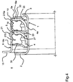
- the embodiment according to Fig. 4 follows the design principle of the sealing ring 170, 170a of the previous exemplary embodiment Fig. 3 . It differs from him only in the radial dimensions of the quad ring 270, 270a.
- the cross section of the quad ring 270, 270a therefore leads, in particular, to a more compact design of the shaft seal than in the exemplary embodiment according to FIG Fig. 3 .
- the cross section of the quad ring 270, 270a is point-symmetrical and can thus be inscribed in a square. In this it is the same as the cross section of the exemplary embodiment Fig. 1 so that all other components of the shaft seal that have the same reference numbers as in Fig. 1 are designated, can be unchanged compared to it, have the properties and functions mentioned there and therefore to avoid Repetitions are not described again, but also as used to Fig. 4 disclosed apply.
- the cross-section of the quad ring 270, 270a leads above all to a comparatively improved radial effective area.
- Fig. 3 explained, it extends in particular radially similarly far inward and thus similarly effectively into the transition area of the sealing element 5, 5a and there comparatively close to the sealing lip 4, 4a. Together with its compact dimensions, it enables a high-performance shaft seal.
- shaft seals described in detail above are exemplary embodiments, they can be modified in a wide scope in the usual manner by the person skilled in the art without departing from the scope of the invention.
- specific configurations of the housing can also take place in a different form than that described here.
Landscapes
- Engineering & Computer Science (AREA)
- General Engineering & Computer Science (AREA)
- Mechanical Engineering (AREA)
- Sealing With Elastic Sealing Lips (AREA)
Abstract
Description
- Die Erfindung betrifft eine Wellendichtung, insbesondere eine Radialwellendichtung, nach dem Oberbegriff des Anspruchs 1.
- Bei Wellendichtungen in Form von Radialwellendichtungen wird als Werkstoff für die Dichtelemente wegen seiner besonderen physikalischen und chemischen Eigenschaften vorteilhaft Polyfluorcarbon eingesetzt, insbesondere Polytetrafluorethylen. Die Dichtelemente sind als Ringscheiben ausgebildet, deren radial innerer Bereich zur Bildung der Dichtlippe elastisch gebogen ist. Bei Polyfluorcarbonen, insbesondere bei Polytetrafluorethylen, ist ein Kriechen zu beobachten. Zudem haben diese Materialien eine verhältnismäßig geringe mechanische Festigkeit. Das Kriechen dieses Werkstoffs führt dazu, dass die Dichtwirkung nachlässt. Um dieser Kriechwirkung zu begegnen, wird darum die radiale Vorspannung, die auf die Dichtlippe wirkt, erhöht. Dies führt aber zu einem entsprechend stärkeren Verschleiß der Dichtlippe. Dichtelementen werden daher unterschiedliche Füllstoffe zugesetzt, die ihre Herstellung verkomplizieren und verteuern.
- Die
DE 10 2012 001 226 beschreibt eine alternative Wellendichtung, insbesondere eine Radialwellendichtung, mit wenigstens einem Dichtelement, das mit einer Dichtlippe versehen ist, die an einer abzudichtenden Fläche unter radialer Kraft anliegt, und mit wenigstens einem Elastomerelement, das die Dichtlippe in Richtung auf die abzudichtende Fläche hin belastet. Geeignete Elastomerelemente können aufgrund ihres Querschnitts nur kostenintensiv hergestellt werden. - Der Erfindung liegt die Aufgabe zugrunde, die gattungsgemäße Wellendichtung so auszubilden, dass sie einfacher und kostengünstiger herzustellen ist.
- Diese Aufgabe wird bei der gattungsgemäßen Wellendichtung erfindungsgemäß mit den kennzeichnenden Merkmalen des Anspruches 1 gelöst.
- Die Wellendichtung umfasst ein Elastomerelement, das das Dichtelement abstützt. Als Elastomerelement dient erfindungsgemäß ein Dichtring. Erfindungsgemäß stützt der Dichtring das Dichtelement derart ab, dass die Dichtlippe, welche die dynamische Abdichtung zur Welle hin bewirkt, in Richtung auf die abzudichtende Fläche hin gedrückt wird. Die Dichtlippe ist regelmäßig in Richtung auf eine Mediumsseite hin gebogen. Der Dichtring kontaktiert nicht die Dichtlippe selbst, sondern einen Übergangsbereich des Dichtelements zur Dichtlippe hin, in dem das Dichtelement bereits gebogen verläuft. Der Dichtring trägt damit wirkungsvoll dazu bei, einer nachlassenden Vorspannung durch Kriechen und durch Verschleiß der Dichtlippe entgegenzuwirken. Als einfaches Bauteil erleichtert der Dichtring seine fehlerfreie Montage, was die Fehlerrate und die Herstellungskosten der Wellendichtung herabsetzt.
- Das Dichtelement kann vorteilhaft als Ringscheibe ausgebildet sein, deren radial innen liegender Bereich zur Bildung der Dichtlippe elastisch gebogen ist. Die Ringscheibe beansprucht wenig Raum und trägt damit zu geringen Abmessungen und einer kostengünstigen Herstellung der Wellendichtung bei.
- Nach einer vorteilhaften Ausgestaltung der Erfindung kann der Dichtring ein O-Ring mit kreisrundem Querschnitt sein. Damit verfügt er über eine geläufige Standardform, weshalb er sich beispielsweise durch Spritzgießen industriell, in großen Stückzahlen und damit kostengünstig herstellen lässt. Aufgrund seiner kostengünstigen und einfachen Verfügbarkeit erfordert er keine kostenträchtige Vorratshaltung. Dies setzt die Herstellungskosten der Wellendichtung herab.
- Nach einer alternativen Ausgestaltung der Erfindung kann der Dichtring einen ovalen Querschnitt aufweisen. Je nach Einbausituation kann der ovale Querschnitt ohne oder mit einer Symmetrieachse oder mit zwei Symmetrieachsen ausgebildet sein. Jedenfalls kann der ovale Querschnitt des Dichtrings derart ausgebildet sein, dass er - schon im unverformten Zustand - eine möglichst große Kontaktfläche mit dem Dichtelement aufweist. Dazu kann der ovale Dichtring derart ausgelegt werden, dass seine größere Querschnittsabmessung in der Wellendichtung radial und die kleinere axial verläuft. Damit kann sich die abstützende Wirkung des Dichtrings über eine größere Fläche des Dichtelements erstrecken und sich damit in radialer Richtung weiter entfalten.
- Nach einer alternativen Ausgestaltung der Erfindung kann der Dichtring ein Quadring sein oder knochenförmigen Querschnitt aufweisen. Der knochenförmige Querschnitt lässt sich beispielsweise durch Formpressen erzielen. Der Quadring kann zwei Kontaktlinien zum Dichtelement bieten, die bezüglich der Abmessungen des Quadrings maximal weit voneinander entfernt liegen. Damit kann es gelingen, die Unterstützung des Dichtelements bzw. den Druck auf die Dichtlippe insbesondere möglichst weit radial einwärts wirken zu lassen. Zudem kann sich das Klaffen einer Kontaktfuge zwischen dem Dichtelement und einem in axialer Richtung wirkenden Abstützelement des Dichtelements vermeiden lassen.
- Die Wellendichtung kann eine Abstützfläche für den Dichtring aufweisen, die dem Dichtelement axial gegenüberliegt und an der der montierte Dichtring anliegt, um eine Stützkraft auf das Dichtelement auszuüben.
- Nach einer weiteren vorteilhaften Ausgestaltung der Erfindung kann die Abstützfläche eine ringförmige Sicke aufweisen. Sie kann durchgehend ausgebildet sein oder mit Unterbrechungen, beispielsweise als nebeneinander angeordnete Vertiefungen. Die radialen Ränder der Sicke konzentrieren eine Kontaktkraft von der Abstützfläche auf den an ihr anliegenden Dichtring auf eine kleinere Fläche, womit die Belastung auf den Dichtring steigt. Außerdem spreizen sie die Krafteinleitung von einer - im entspannten Zustand - in radialer Richtung schmalen Krafteinleitungsfläche auf zwei Einleitungsbereiche am Dichtring. Der Dichtring kann damit seine Stützkraft über einen breiten Bereich hinweg weiterleiten.
- Nach einer weiteren vorteilhaften Ausgestaltung der Erfindung kann die abzudichtende Fläche die Mantelfläche einer Welle oder einer Achse sein. Damit lässt sich eine kompakte Bauform erreichen.
- Alternativ kann die abzudichtende Fläche die Mantelfläche einer Laufhülse sein, die drehfest auf einer Welle oder Achse sitzt. Das Dichtelement hat damit keinen direkten Kontakt mit der Welle oder Achse. Das Material der Laufhülse dagegen kann auf ein optimales Zusammenwirken mit dem Dichtelement hin ausgewählt sein.
- Nach einer weiteren vorteilhaften Ausgestaltung der Erfindung kann eine Mehrzahl an Dichtelementen axial nebeneinander angeordnet sein, die mit einer Seite an jeweils einem Abstützelement anliegen. Damit kann sich die Dichtwirkung der Wellendichtung steigern und höheren Anforderungen anpassen lassen, womit sich der Einsatzbereich der Wellendichtung vergrößern lässt.
- Vorteilhafterweise können die Dichtelemente dann mit ihrer anderen Seite an einem oben näher beschriebenen Dichtring anliegen.
- Der Anmeldungsgegenstand ergibt sich nicht nur aus dem Gegenstand der einzelnen Patentansprüche, sondern auch durch alle in den Zeichnungen und der Beschreibung offenbarten Angaben und Merkmale. Sie werden, auch wenn sie nicht Gegenstand der Ansprüche sind, als erfindungswesentlich beansprucht, soweit sie einzeln oder in Kombination gegenüber dem Stand der Technik neu sind.
- Weitere Merkmale der Erfindung ergeben sich aus den weiteren Ansprüchen, der Beschreibung und den Zeichnungen.
- Das Prinzip der Erfindung wird im Folgenden anhand einiger in den Zeichnungen dargestellter Ausführungsformen näher erläutert. Es zeigen
- Fig. 1 bis 4
- jeweils im Axialhalbschnitt verschiedene Ausführungsbeispiele von erfindungsgemäßen Wellendichtungen.
- Die Wellendichtung gemäß
Fig. 1 hat eine Laufhülse 1, die drehfest auf einer abzudichtenden (nicht dargestellten) Welle sitzt. Die Laufhülse 1 sitzt vorzugsweise mit Presssitz auf der abzudichtenden Welle. An einem Ende hat die Laufhülse 1 einen radial nach außen gerichteten Ringflansch 2. Das andere Ende 3 der Laufhülse 1 kann trichterförmig aufgeweitet sein. Die radiale Breite des Ringflansches 2 ist größer als die radiale Breite des aufgeweiteten Endes 3. Das trichterförmig erweiterte Ende 3 der Laufhülse 1 trägt zu einer besseren Zentrierung bei der Montage der Wellendichtung bei und kann als Transportsicherung sowie auch zur Kapselung einer Vorschmierung gegen Verschleppung und Verunreinigung dienen. - Auf der zylinderförmigen Außenseite der Laufhülse 1 bzw. ihrer Mantelfläche 27 liegen zwei Dichtlippen 4, 4a zweier Dichtelemente 5, 5a unter radialer Vorspannung dichtend an. Sie bilden einen Bestandteil einer dynamischen Abdichtung der Wellendichtung. Alternativ können auch nur ein Dichtelement oder mehr als zwei Dichtelemente vorgesehen sein. Das Dichtelement 5, 5a ist vorteilhaft eine Dichtscheibe, deren radial innen liegender Bereich zur Bildung der Dichtlippe 4, 4a elastisch gebogen ist. Die Dichtlippe 4, 4a ist in Richtung auf eine Mediumsseite 6 hin elastisch gebogen.
- An seiner von der Mediumsseite 6 abgewandten Seite liegt jedes Dichtelement 5, 5a an einer Abstützscheibe 19, 19a an. Sie liegen mit ihrem radial inneren Bereich 20 flächig am Übergangsbereich des Dichtelementes 5, 5a in die Dichtlippe 4, 4a an und sind mit ihrem radial inneren Abschnitt in Richtung auf die Mediumsseite 6 hin gebogen. Eine weitere Abstützscheibe 19b ist an einer der Mediumsseite 6 zugewandten Seite und äquidistant zu den Abstützscheiben 19, 19a angebracht. Die Abstützscheibe 19b übergreift, in Achsrichtung der Wellendichtung gesehen, den Ringflansch 2 der Laufhülse 1, der axialen Abstand von der Abstützscheibe 19b hat.
- Die Abstützscheiben 19, 19a, 19b erstrecken sich radial bis zu einem zylindrischen Mantel 10 eines Gehäuses 9, an dem die Abstützscheiben 19, 19b mit ihrem radial äußeren Rand vorteilhaft befestigt sind. Die Abstützscheibe 19a geht rechtwinklig in den Mantel 10 über, mit dem die Abstützscheibe 19a vorteilhaft einstückig ausgebildet ist. Das andere Ende des Mantels 10 geht rechtwinklig in einen radial nach außen gerichteten Ringflansch 13 über. Mit ihm liegt das Gehäuse 9 in der Einbaulage der Wellendichtung in bekannter Weise an einer eine Aufnahmeöffnung für die Wellendichtung aufweisenden Seite eines Aggregats an. Das Gehäuse 9 ist vorteilhaft einstückig ausgebildet und besteht vorteilhaft aus metallischem Material. Je nach Einsatzgebiet der Wellendichtung kann das Gehäuse 9 aus einem geeigneten, vorzugsweise aus hartem Kunststoff bestehen.
- Bestehen die Abstützscheiben 19, 19b aus metallischem Werkstoff, dann sind sie vorteilhaft an den Mantel 10 angeschweißt. Sie können alternativ auch eingepresst sein.
- Auf der Außenseite des Mantel 10 des Gehäuses 9 befindet sich ein Dichtmittel 21, das eine statische Abdichtung in der Einbaulage der Wellendichtung bildet. Das Dichtmittel 21 kann zum Beispiel, wie dargestellt, als Dichtraupe oder als flächige Schicht aufgebracht sein und erstreckt sich ringförmig über den Umfang des Mantels 10. In der Einbaulage der Wellendichtung wird das Dichtmittel 21 elastisch verformt und sorgt somit für eine zuverlässige statische Abdichtung.
- An der der Mediumsseite 6 zugewandten Seite ist jedes Dichtelement 5, 5a von einem O-Ring 7, 7a als Elastomerelement abschnittsweise bedeckt. Der O-Ring 7, 7a hat einen kreisringförmigen Querschnitt und liegt über einen Umfangsabschnitt hinweg und damit flächig am Dichtelement 5, 5a bis in dessen Übergangsbereich zur Dichtlippe 4, 4a an. Er besteht aus elastischem Kunststoff, Gummi, einem gummiähnlichen Material und dgl.
- Der O-Ring 7, 7a liegt an seiner der Mediumsseite 6 zugewandten Seite axial an der Abstützscheibe 19 bzw. 19b an. Er wird unter Vorspannung zwischen das Dichtelement 5, 5a und die Abstützscheiben 19, 19b eingesetzt, so dass er sich verformt (nicht dargestellt) und dadurch eine Drucckraft auf das Dichtelement 5, 5a und dessen Übergangsbereich zur Dichtlippe 4, 4a aufbringt.
- Der kreisförmige Querschnitt des O-Rings 7, 7a ermöglicht einen sehr kompakten Aufbau der Wellendichtung. Als Standardbauteil ist der O-Ring 7, 7a kostengünstig und einfach erhältlich.
- Die Abstützscheiben 19, 19a, 19b weisen jeweils eine ringförmig umlaufende Sicke 30 auf. Sie kann alternativ als ringförmige Anordnung von Vertiefungen und damit quasi mit Unterbrechungen ausgebildet sein. Die Sicke 30 erhöht die Steifigkeit der Abstützscheiben 19, 19a, 19b, so dass sie ihre Steifigkeit nicht allein aus ihrer Materialdicke beziehen müssen. Sie können daher bei gleicher Belastbarkeit schlanker ausgebildet werden, womit die Wellendichtung kompakter und ihre Herstellung kostengünstiger ausfallen kann.
- Die Sicke ist außerdem so angebracht, dass sie in der Kontaktfläche jeweils der Abstützscheiben 19, 19b und der montierten O-Ringe 7, 7a liegt. Damit beeinflusst sie die Druckwirkung des O-Rings 7, 7a, weil sie die ursprünglich konzentrierte Kontaktfläche, die ohne Belastung des O-Rings 7, 7a im gezeigten Querschnitt punktförmig wäre, vergrößert. Unter Belastung des O-Rings 7, 7a entlastet die Sicke 30 zwar einen zentralen Bereich der Kontaktfläche des O-Rings 7, 7a, erhöht aber die Belastung beidseits des zentralen Bereichs und konzentriert sie durch die Ränder der Sicke 30 auf kleinem Raum.
- Vorteilhaft liegen die O-Ringe 7, 7a auch an der Innenseite des Mantels 10 an, wodurch die Dichtringe 7, 7a in radialer Richtung abgestützt sind.
- Das Dichtelement 5, 5a ist in der beschriebenen Weise zwischen dem O-Ring 7, 7a und der Abstützscheibe 19, 19a angeordnet und liegt an ihnen jeweils an. Die Abstützscheiben 19, 19a, 19b fixieren die Einzelteile 7, 7a, 5, 5a der Wellendichtung. Von den Dichtlippen 4, 4a haben die O-Ringe 7, 7a, ausreichend Abstand, so dass sie die Beweglichkeit der Dichtlippen 4, 4a nicht behindern.
- Die Abstützscheiben 19, 19a, 19b und/oder der O-Ring 7, 7a können mit dem Dichtelement 5, 5a chemisch und/oder mechanisch verbunden sein.
- Das Ausführungsbeispiel gemäß
Fig. 2 unterscheidet sich von dem zuvor beschriebenen Ausführungsbeispiel durch einen abweichenden Querschnitt des O-Rings 70, 70a. Er hat statt eines kreisringförmigen einen ovalen Querschnitt, insbesondere einen symmetrischen Querschnitt mit jeweils zwei einander gegenüberliegenden Kreisbögen und geraden Stücken. Der O-Ring 70, 70a ist so angeordnet, dass seine geringere Breite axial verläuft. - Da die Wellendichtung infolge des ovalen Querschnitts des O-Rings 70, 70a in Radialrichtung breiter ist, sind auch die Abstützringe 19, 19a, 19b radial breiter als beim vorigen Ausführungsbeispiel. Entsprechend abweichend ist auch das Dichtelement 5, 5a dimensioniert, dessen an der Abstützscheibe 19, 19a liegender Bereich radial breiter ist als bei der vorigen Ausführungsform. Die Sicke 30 ist aufgrund des ovalen Querschnitts des O-Rings 70, 70a von untergeordneter Bedeutung, weshalb sie hier entbehrlich ist, aber selbstverständlich vorgesehen sein kann.
- Alle übrigen Bestandteile der Wellendichtung, die mit demselben Bezugszeichen wie im vorigen Ausführungsbeispiel bezeichnet sind, sind unverändert, haben die dort genannten Eigenschaften und Funktionen und werden daher zur Vermeidung von Wiederholungen nicht erneut beschrieben, sondern gelten als auch zur
Fig. 2 offenbart. - Die in radialer Richtung breitere Dimensionierung des Dichtrings 70, 70a hat - neben den oben bereits genannten Effekten - den weiteren Vorteil eines radial größeren Wirkbereichs. Der O-Ring 70, 70a stützt folglich das ihm zugeordnete Dichtelement 5, 5a über eine größere radiale Länge ab, was der Dichtwirkung der Wellendichtung zugutekommt. Dies beruht nicht nur auf einer größeren Kontaktfläche des O-Rings 70, 70a mit der Abstützscheibe 19, 19b einerseits und mit dem Dichtelement 5, 5a andererseits, sondern auch in der weiter in den Übergangsbereich des Dichtelements 5, 5a zu dessen Dichtlippe 4, 4a hin wirkenden Abstützung. Die Abstützung hält nicht nur die Vorspannung der Dichtlippe 4, 4a aufrecht, sondern verhindert auch eine Ablösung des Dichtelements 5, 5a vom Abstützring 19, 19a in einer radial auswärts führenden Richtung.
- Das Ausführungsbeispiel gemäß
Fig. 3 unterscheidet sich von dem zuvor beschriebenen Ausführungsbeispiel derFig. 2 durch einen abweichenden Querschnitt des Dichtrings 170, 170a. Der Querschnitt lässt sich als knochenförmig bezeichnen. Er ergibt sich von einer Rechteckform ausgehend durch eine starke Abrundung der Ecken durch Halbkreise (im Axialschnitt gesehen), die anstelle der Seiten des Rechtecks fließend in bogenförmige bzw. konkave Einschnürungen übergehen. Dadurch ergibt sich eine Materialverteilung des Dichtrings 170, 170a, die zu einer höheren Konzentration des elastischen Materials in vier Bereichen am Umfang des Dichtrings 170, 170a führt. - Er kann Außenabmessungen aufweisen, die prinzipiell denen des O-Rings 70, 70a der
Fig. 2 in radialer und in axialer Richtung entsprechen. Damit können alle übrigen Bestandteile der Wellendichtung grundsätzlich identisch dimensioniert sein und dieselben Eigenschaften und Funktionen wie dort bieten, weshalb sie zur Vermeidung von Wiederholungen nicht erneut beschrieben werden, sondern auch als zurFig. 3 offenbart gelten. Lediglich die Sicke 30 wäre wegen der besonderen Querschnittsform des Dichtrings 170, 170a wirkungslos, weshalb sie entfallen kann. - Der besondere knochenförmige Querschnitt des Dichtrings 170, 170a führt trotz vor allem radial identischer Abmessungen wie in
Fig. 2 zu einem demgegenüber verbesserten radialen Wirkbereich. Denn nicht nur die Abstützung des Dichtrings 170, 170a am jeweiligen Abstützring 19, 19b verlagert sich in einen, in radialer Richtung betrachtet, umfangsnahen Bereich des Dichtrings 170, 170a. Auch seine Stütz- und Krafteinwirkung auf das Dichtelement 5, 5a ist in gleicher Weise radial gespreizt, so dass er insbesondere radial noch weiter nach innen und damit noch effektiver in den Übergangsbereich des Dichtelements 5, 5a und dort noch näher zur Dichtlippe 4, 4a hin wirkt. - Das Ausführungsbeispiel gemäß
Fig. 4 folgt dem Gestaltungsprinzip des Dichtrings 170, 170a des vorangehenden Ausführungsbeispiels derFig. 3 . Es unterscheidet sich von ihm lediglich in den radialen Abmessungen des Quadrings 270, 270a. Der Querschnitt des Quadrings 270, 270a führt daher insbesondere zu einem kompakteren Aufbau der Wellendichtung als im Ausführungsbeispiel gemäßFig. 3 . - Der Querschnitt des Quadrings 270, 270a ist punktsymmetrisch und lässt sich damit einem Quadrat einbeschreiben. Darin gleicht er dem Querschnitt des Ausführungsbeispiels gemäß
Fig. 1 , so dass alle übrigen Bestandteile der Wellendichtung, die mit demselben Bezugszeichen wie inFig. 1 bezeichnet sind, ihr gegenüber unverändert sein können, die dort genannten Eigenschaften und Funktionen besitzen und daher zur Vermeidung von Wiederholungen nicht erneut beschrieben werden, sondern auch als zurFig. 4 offenbart gelten. - Im Unterschied zum Ausführungsbeispiel gemäß
Fig. 1 führt der Querschnitt des Quadrings 270, 270a vor allem zu einem demgegenüber verbesserten radialen Wirkbereich. Wie oben zurFig. 3 erläutert, reicht er insbesondere radial ähnlich weit nach innen und damit ähnlich effektiv in den Übergangsbereich des Dichtelements 5, 5a und dort vergleichbar nahe zur Dichtlippe 4, 4a hin. Zusammen mit seinen kompakten Abmessungen ermöglicht er so eine hochleistungsfähige Wellendichtung. - Da es sich bei den vorhergehenden, detailliert beschriebenen Wellendichtungen um Ausführungsbeispiele handelt, können sie in üblicher Weise vom Fachmann in einem weiten Umfang modifiziert werden, ohne den Bereich der Erfindung zu verlassen. Insbesondere können auch die konkreten Ausgestaltungen des Gehäuses in anderer Form als in der hier beschriebenen erfolgen.
Claims (9)
- Wellendichtung, insbesondere Radialwellendichtung, mit wenigstens einem Dichtelement aus Polyfluorcarbon, vorzugsweise aus Polytetrafluorethylen, das mit einer Dichtlippe versehen ist, die an einer abzudichtenden Fläche unter radialer Kraft anliegt, und mit wenigstens einem Elastomerelement, das das Dichtelement abstützt, gekennzeichnet durch einen Dichtring (7, 7a, 70, 70a, 170, 170a, 270, 270a) als Elastomerelement.
- Wellendichtung nach Anspruch 1,
dadurch gekennzeichnet, dass der Dichtring (7, 7a) einen kreisrunden Querschnitt aufweist. - Wellendichtung nach Anspruch 1,
dadurch gekennzeichnet, dass der Dichtring (70, 70a) einen ovalen Querschnitt aufweist. - Wellendichtung nach Anspruch 1,
dadurch gekennzeichnet, dass der Dichtring (170, 170a, 270, 270a) ein Quadring ist oder einen knochenförmigen Querschnitt aufweist. - Wellendichtung nach einem der Ansprüche 1 bis 4,
dadurch gekennzeichnet, dass der Dichtring (7, 7a, 70, 70a, 170, 170a, 270, 270a) an einer Abstützfläche (19, 19a, 19b) anliegt. - Wellendichtung nach Anspruch 5,
dadurch gekennzeichnet, dass in der Abstützfläche (19, 19a, 19b) wenigstens eine Sicke (30) vorgesehen ist. - Wellendichtung nach einem der Ansprüche 1 bis 6,
dadurch gekennzeichnet, dass die abzudichtende Fläche die Mantelfläche einer Welle oder einer Achse ist. - Wellendichtung nach einem der Ansprüche 1 bis 7,
dadurch gekennzeichnet, dass die abzudichtende Fläche die Mantelfläche (27) einer Laufhülse (1) ist, die drehfest auf einer Welle oder Achse sitzt. - Wellendichtung nach einem der Ansprüche 1 bis 8,
dadurch gekennzeichnet, dass eine Mehrzahl an Dichtelementen (5, 5a) axial nebeneinander angeordnet ist, die mit einer Seite an jeweils einer Abstützfläche (19, 19a) anliegen.
Applications Claiming Priority (1)
| Application Number | Priority Date | Filing Date | Title |
|---|---|---|---|
| DE102019008984.7A DE102019008984A1 (de) | 2019-12-23 | 2019-12-23 | Wellendichtung, insbesondere Radialwellendichtung, mit wenigstens einem Dichtelement |
Publications (2)
| Publication Number | Publication Date |
|---|---|
| EP3842671A1 true EP3842671A1 (de) | 2021-06-30 |
| EP3842671B1 EP3842671B1 (de) | 2024-05-15 |
Family
ID=74184339
Family Applications (1)
| Application Number | Title | Priority Date | Filing Date |
|---|---|---|---|
| EP20000490.1A Active EP3842671B1 (de) | 2019-12-23 | 2020-12-23 | Wellendichtung, insbesondere radialwellendichtung, mit wenigstens einem dichtelement |
Country Status (3)
| Country | Link |
|---|---|
| EP (1) | EP3842671B1 (de) |
| CN (1) | CN113090758B (de) |
| DE (1) | DE102019008984A1 (de) |
Citations (5)
| Publication number | Priority date | Publication date | Assignee | Title |
|---|---|---|---|---|
| GB2181191A (en) * | 1985-09-27 | 1987-04-15 | Fenner Co Ltd J H | Fluid seals |
| US4819952A (en) * | 1987-02-02 | 1989-04-11 | Busak + Luyken Gmbh & Co. | Sealing and wiper arrangement |
| US6428013B1 (en) * | 1999-01-29 | 2002-08-06 | Freudenberg-Nok General Partnership | Reverse seal |
| DE102012001226A1 (de) | 2012-01-19 | 2013-07-25 | Kaco Gmbh + Co. Kg | Wellendichtung, insbesondere Radialwellendichtung |
| WO2018211073A1 (de) * | 2017-05-19 | 2018-11-22 | Trelleborg Sealing Solutions Germany Gmbh | Rotationsdichtungsanordnung und rotationsdichtung mit rückförderfunktion |
Family Cites Families (6)
| Publication number | Priority date | Publication date | Assignee | Title |
|---|---|---|---|---|
| IT1053388B (it) * | 1975-02-20 | 1981-08-31 | Garlock Inc | Perfezionamento nei dispositivi di tenuta per alberi ruotanti |
| CN2521446Y (zh) * | 2002-01-30 | 2002-11-20 | 青岛基珀密封工业有限公司 | 组合油封 |
| CA2628599C (en) * | 2005-11-15 | 2013-04-09 | Ashbridge & Roseburgh Inc. | Sequentially-deployable lip seal systems |
| WO2007069597A1 (ja) * | 2005-12-13 | 2007-06-21 | Mitsubishi Cable Industries, Ltd. | 回転軸シール及びその製法 |
| DE102017203083A1 (de) * | 2017-02-24 | 2018-08-30 | Aktiebolaget Skf | Schaftdichtung |
| DE102017011930A1 (de) * | 2017-12-21 | 2019-06-27 | Carl Freudenberg Kg | Dichtungsanordnung |
-
2019
- 2019-12-23 DE DE102019008984.7A patent/DE102019008984A1/de not_active Ceased
-
2020
- 2020-12-22 CN CN202011525890.XA patent/CN113090758B/zh active Active
- 2020-12-23 EP EP20000490.1A patent/EP3842671B1/de active Active
Patent Citations (5)
| Publication number | Priority date | Publication date | Assignee | Title |
|---|---|---|---|---|
| GB2181191A (en) * | 1985-09-27 | 1987-04-15 | Fenner Co Ltd J H | Fluid seals |
| US4819952A (en) * | 1987-02-02 | 1989-04-11 | Busak + Luyken Gmbh & Co. | Sealing and wiper arrangement |
| US6428013B1 (en) * | 1999-01-29 | 2002-08-06 | Freudenberg-Nok General Partnership | Reverse seal |
| DE102012001226A1 (de) | 2012-01-19 | 2013-07-25 | Kaco Gmbh + Co. Kg | Wellendichtung, insbesondere Radialwellendichtung |
| WO2018211073A1 (de) * | 2017-05-19 | 2018-11-22 | Trelleborg Sealing Solutions Germany Gmbh | Rotationsdichtungsanordnung und rotationsdichtung mit rückförderfunktion |
Also Published As
| Publication number | Publication date |
|---|---|
| EP3842671B1 (de) | 2024-05-15 |
| CN113090758B (zh) | 2025-10-10 |
| DE102019008984A1 (de) | 2021-06-24 |
| CN113090758A (zh) | 2021-07-09 |
Similar Documents
| Publication | Publication Date | Title |
|---|---|---|
| EP2024653B1 (de) | Wälzlager mit zwei innenringen und einer dichtungsanordnung zur abdichtung der trennfuge zwischen den innenringen | |
| EP2397727B1 (de) | Mehrteiliger Ventilteller | |
| DE102010046431A1 (de) | Umlaufende Dichtungsanordnung | |
| EP2638302B1 (de) | Abgedichtetes wälzlager | |
| WO2008014768A2 (de) | Abgedichtetes wälzlager | |
| DE102008010338A1 (de) | Radialwellendichtung für Kraftfahrzeug-Wasserpumpen | |
| EP2618032B1 (de) | Wellendichtung, insbesondere Radialwellendichtung | |
| EP3728910B1 (de) | Dichtungsanordnung | |
| DE102018201820A1 (de) | Grosswälzlager mit zumindest zwei Reihen von Wälzelementen | |
| DE3612420C2 (de) | ||
| DE2257760C3 (de) | Dichtung für ein Wälzlager | |
| DE102005061168A1 (de) | Radiallager mit einer Kassettendichtung, sowie Kassettendichtung | |
| DE10113442C2 (de) | Lageranordnung für ein Wellenlager | |
| DE112017007969T5 (de) | Kolbendichtungsbaugruppe für ein Kupplungsausrücksystem sowie Kupplungsausrücksystem | |
| DE102015215315A1 (de) | Wälzlager und Montageverfahren | |
| DE102018130926A1 (de) | Radlagereinheit | |
| DE102010010638A1 (de) | Ringförmiges, axiales Sicherungselement | |
| DE102008029642A1 (de) | Tellerfederanordnung | |
| EP3842671B1 (de) | Wellendichtung, insbesondere radialwellendichtung, mit wenigstens einem dichtelement | |
| DE10160990B4 (de) | Gelenk mit Gelenklagerhülse | |
| DE4317483A1 (de) | Kolben, insbesondere für den Servozylinder einer Hilfskraftlenkanlage | |
| EP3417192B1 (de) | Wellendichtung | |
| DE102014011473B3 (de) | Dichtungsanordnung | |
| DE2111312A1 (de) | Nutringdichtung | |
| DE102018105992A1 (de) | Zweireihiges Rollenlager, insbesondere Kegelrollenlager |
Legal Events
| Date | Code | Title | Description |
|---|---|---|---|
| PUAI | Public reference made under article 153(3) epc to a published international application that has entered the european phase |
Free format text: ORIGINAL CODE: 0009012 |
|
| STAA | Information on the status of an ep patent application or granted ep patent |
Free format text: STATUS: THE APPLICATION HAS BEEN PUBLISHED |
|
| AK | Designated contracting states |
Kind code of ref document: A1 Designated state(s): AL AT BE BG CH CY CZ DE DK EE ES FI FR GB GR HR HU IE IS IT LI LT LU LV MC MK MT NL NO PL PT RO RS SE SI SK SM TR |
|
| STAA | Information on the status of an ep patent application or granted ep patent |
Free format text: STATUS: REQUEST FOR EXAMINATION WAS MADE |
|
| 17P | Request for examination filed |
Effective date: 20220103 |
|
| RBV | Designated contracting states (corrected) |
Designated state(s): AL AT BE BG CH CY CZ DE DK EE ES FI FR GB GR HR HU IE IS IT LI LT LU LV MC MK MT NL NO PL PT RO RS SE SI SK SM TR |
|
| STAA | Information on the status of an ep patent application or granted ep patent |
Free format text: STATUS: EXAMINATION IS IN PROGRESS |
|
| 17Q | First examination report despatched |
Effective date: 20221118 |
|
| REG | Reference to a national code |
Ref country code: DE Ref legal event code: R079 Free format text: PREVIOUS MAIN CLASS: F16J0015320800 Ipc: F16J0015325600 Ref country code: DE Ref legal event code: R079 Ref document number: 502020007972 Country of ref document: DE Free format text: PREVIOUS MAIN CLASS: F16J0015320800 Ipc: F16J0015325600 |
|
| GRAP | Despatch of communication of intention to grant a patent |
Free format text: ORIGINAL CODE: EPIDOSNIGR1 |
|
| STAA | Information on the status of an ep patent application or granted ep patent |
Free format text: STATUS: GRANT OF PATENT IS INTENDED |
|
| RIC1 | Information provided on ipc code assigned before grant |
Ipc: F16J 15/3232 20160101ALI20231128BHEP Ipc: F16J 15/3208 20160101ALI20231128BHEP Ipc: F16J 15/3228 20160101ALI20231128BHEP Ipc: F16J 15/3256 20160101AFI20231128BHEP |
|
| INTG | Intention to grant announced |
Effective date: 20231220 |
|
| GRAS | Grant fee paid |
Free format text: ORIGINAL CODE: EPIDOSNIGR3 |
|
| GRAA | (expected) grant |
Free format text: ORIGINAL CODE: 0009210 |
|
| STAA | Information on the status of an ep patent application or granted ep patent |
Free format text: STATUS: THE PATENT HAS BEEN GRANTED |
|
| AK | Designated contracting states |
Kind code of ref document: B1 Designated state(s): AL AT BE BG CH CY CZ DE DK EE ES FI FR GB GR HR HU IE IS IT LI LT LU LV MC MK MT NL NO PL PT RO RS SE SI SK SM TR |
|
| REG | Reference to a national code |
Ref country code: CH Ref legal event code: EP |
|
| REG | Reference to a national code |
Ref country code: DE Ref legal event code: R096 Ref document number: 502020007972 Country of ref document: DE |
|
| REG | Reference to a national code |
Ref country code: IE Ref legal event code: FG4D Free format text: LANGUAGE OF EP DOCUMENT: GERMAN |
|
| REG | Reference to a national code |
Ref country code: LT Ref legal event code: MG9D |
|
| REG | Reference to a national code |
Ref country code: NL Ref legal event code: MP Effective date: 20240515 |
|
| PG25 | Lapsed in a contracting state [announced via postgrant information from national office to epo] |
Ref country code: IS Free format text: LAPSE BECAUSE OF FAILURE TO SUBMIT A TRANSLATION OF THE DESCRIPTION OR TO PAY THE FEE WITHIN THE PRESCRIBED TIME-LIMIT Effective date: 20240915 |
|
| PG25 | Lapsed in a contracting state [announced via postgrant information from national office to epo] |
Ref country code: BG Free format text: LAPSE BECAUSE OF FAILURE TO SUBMIT A TRANSLATION OF THE DESCRIPTION OR TO PAY THE FEE WITHIN THE PRESCRIBED TIME-LIMIT Effective date: 20240515 |
|
| PG25 | Lapsed in a contracting state [announced via postgrant information from national office to epo] |
Ref country code: FI Free format text: LAPSE BECAUSE OF FAILURE TO SUBMIT A TRANSLATION OF THE DESCRIPTION OR TO PAY THE FEE WITHIN THE PRESCRIBED TIME-LIMIT Effective date: 20240515 Ref country code: HR Free format text: LAPSE BECAUSE OF FAILURE TO SUBMIT A TRANSLATION OF THE DESCRIPTION OR TO PAY THE FEE WITHIN THE PRESCRIBED TIME-LIMIT Effective date: 20240515 |
|
| PG25 | Lapsed in a contracting state [announced via postgrant information from national office to epo] |
Ref country code: GR Free format text: LAPSE BECAUSE OF FAILURE TO SUBMIT A TRANSLATION OF THE DESCRIPTION OR TO PAY THE FEE WITHIN THE PRESCRIBED TIME-LIMIT Effective date: 20240816 |
|
| PG25 | Lapsed in a contracting state [announced via postgrant information from national office to epo] |
Ref country code: PT Free format text: LAPSE BECAUSE OF FAILURE TO SUBMIT A TRANSLATION OF THE DESCRIPTION OR TO PAY THE FEE WITHIN THE PRESCRIBED TIME-LIMIT Effective date: 20240916 |
|
| PG25 | Lapsed in a contracting state [announced via postgrant information from national office to epo] |
Ref country code: NL Free format text: LAPSE BECAUSE OF FAILURE TO SUBMIT A TRANSLATION OF THE DESCRIPTION OR TO PAY THE FEE WITHIN THE PRESCRIBED TIME-LIMIT Effective date: 20240515 |
|
| PG25 | Lapsed in a contracting state [announced via postgrant information from national office to epo] |
Ref country code: ES Free format text: LAPSE BECAUSE OF FAILURE TO SUBMIT A TRANSLATION OF THE DESCRIPTION OR TO PAY THE FEE WITHIN THE PRESCRIBED TIME-LIMIT Effective date: 20240515 |
|
| PG25 | Lapsed in a contracting state [announced via postgrant information from national office to epo] |
Ref country code: PL Free format text: LAPSE BECAUSE OF FAILURE TO SUBMIT A TRANSLATION OF THE DESCRIPTION OR TO PAY THE FEE WITHIN THE PRESCRIBED TIME-LIMIT Effective date: 20240515 |
|
| PG25 | Lapsed in a contracting state [announced via postgrant information from national office to epo] |
Ref country code: LV Free format text: LAPSE BECAUSE OF FAILURE TO SUBMIT A TRANSLATION OF THE DESCRIPTION OR TO PAY THE FEE WITHIN THE PRESCRIBED TIME-LIMIT Effective date: 20240515 |
|
| PG25 | Lapsed in a contracting state [announced via postgrant information from national office to epo] |
Ref country code: PT Free format text: LAPSE BECAUSE OF FAILURE TO SUBMIT A TRANSLATION OF THE DESCRIPTION OR TO PAY THE FEE WITHIN THE PRESCRIBED TIME-LIMIT Effective date: 20240916 Ref country code: PL Free format text: LAPSE BECAUSE OF FAILURE TO SUBMIT A TRANSLATION OF THE DESCRIPTION OR TO PAY THE FEE WITHIN THE PRESCRIBED TIME-LIMIT Effective date: 20240515 Ref country code: NO Free format text: LAPSE BECAUSE OF FAILURE TO SUBMIT A TRANSLATION OF THE DESCRIPTION OR TO PAY THE FEE WITHIN THE PRESCRIBED TIME-LIMIT Effective date: 20240815 Ref country code: NL Free format text: LAPSE BECAUSE OF FAILURE TO SUBMIT A TRANSLATION OF THE DESCRIPTION OR TO PAY THE FEE WITHIN THE PRESCRIBED TIME-LIMIT Effective date: 20240515 Ref country code: LV Free format text: LAPSE BECAUSE OF FAILURE TO SUBMIT A TRANSLATION OF THE DESCRIPTION OR TO PAY THE FEE WITHIN THE PRESCRIBED TIME-LIMIT Effective date: 20240515 Ref country code: IS Free format text: LAPSE BECAUSE OF FAILURE TO SUBMIT A TRANSLATION OF THE DESCRIPTION OR TO PAY THE FEE WITHIN THE PRESCRIBED TIME-LIMIT Effective date: 20240915 Ref country code: HR Free format text: LAPSE BECAUSE OF FAILURE TO SUBMIT A TRANSLATION OF THE DESCRIPTION OR TO PAY THE FEE WITHIN THE PRESCRIBED TIME-LIMIT Effective date: 20240515 Ref country code: GR Free format text: LAPSE BECAUSE OF FAILURE TO SUBMIT A TRANSLATION OF THE DESCRIPTION OR TO PAY THE FEE WITHIN THE PRESCRIBED TIME-LIMIT Effective date: 20240816 Ref country code: FI Free format text: LAPSE BECAUSE OF FAILURE TO SUBMIT A TRANSLATION OF THE DESCRIPTION OR TO PAY THE FEE WITHIN THE PRESCRIBED TIME-LIMIT Effective date: 20240515 Ref country code: ES Free format text: LAPSE BECAUSE OF FAILURE TO SUBMIT A TRANSLATION OF THE DESCRIPTION OR TO PAY THE FEE WITHIN THE PRESCRIBED TIME-LIMIT Effective date: 20240515 Ref country code: BG Free format text: LAPSE BECAUSE OF FAILURE TO SUBMIT A TRANSLATION OF THE DESCRIPTION OR TO PAY THE FEE WITHIN THE PRESCRIBED TIME-LIMIT Effective date: 20240515 Ref country code: RS Free format text: LAPSE BECAUSE OF FAILURE TO SUBMIT A TRANSLATION OF THE DESCRIPTION OR TO PAY THE FEE WITHIN THE PRESCRIBED TIME-LIMIT Effective date: 20240815 |
|
| PG25 | Lapsed in a contracting state [announced via postgrant information from national office to epo] |
Ref country code: DK Free format text: LAPSE BECAUSE OF FAILURE TO SUBMIT A TRANSLATION OF THE DESCRIPTION OR TO PAY THE FEE WITHIN THE PRESCRIBED TIME-LIMIT Effective date: 20240515 |
|
| PG25 | Lapsed in a contracting state [announced via postgrant information from national office to epo] |
Ref country code: EE Free format text: LAPSE BECAUSE OF FAILURE TO SUBMIT A TRANSLATION OF THE DESCRIPTION OR TO PAY THE FEE WITHIN THE PRESCRIBED TIME-LIMIT Effective date: 20240515 |
|
| PG25 | Lapsed in a contracting state [announced via postgrant information from national office to epo] |
Ref country code: CZ Free format text: LAPSE BECAUSE OF FAILURE TO SUBMIT A TRANSLATION OF THE DESCRIPTION OR TO PAY THE FEE WITHIN THE PRESCRIBED TIME-LIMIT Effective date: 20240515 |
|
| PG25 | Lapsed in a contracting state [announced via postgrant information from national office to epo] |
Ref country code: RO Free format text: LAPSE BECAUSE OF FAILURE TO SUBMIT A TRANSLATION OF THE DESCRIPTION OR TO PAY THE FEE WITHIN THE PRESCRIBED TIME-LIMIT Effective date: 20240515 Ref country code: SK Free format text: LAPSE BECAUSE OF FAILURE TO SUBMIT A TRANSLATION OF THE DESCRIPTION OR TO PAY THE FEE WITHIN THE PRESCRIBED TIME-LIMIT Effective date: 20240515 |
|
| PG25 | Lapsed in a contracting state [announced via postgrant information from national office to epo] |
Ref country code: SM Free format text: LAPSE BECAUSE OF FAILURE TO SUBMIT A TRANSLATION OF THE DESCRIPTION OR TO PAY THE FEE WITHIN THE PRESCRIBED TIME-LIMIT Effective date: 20240515 |
|
| PG25 | Lapsed in a contracting state [announced via postgrant information from national office to epo] |
Ref country code: SM Free format text: LAPSE BECAUSE OF FAILURE TO SUBMIT A TRANSLATION OF THE DESCRIPTION OR TO PAY THE FEE WITHIN THE PRESCRIBED TIME-LIMIT Effective date: 20240515 Ref country code: SK Free format text: LAPSE BECAUSE OF FAILURE TO SUBMIT A TRANSLATION OF THE DESCRIPTION OR TO PAY THE FEE WITHIN THE PRESCRIBED TIME-LIMIT Effective date: 20240515 Ref country code: RO Free format text: LAPSE BECAUSE OF FAILURE TO SUBMIT A TRANSLATION OF THE DESCRIPTION OR TO PAY THE FEE WITHIN THE PRESCRIBED TIME-LIMIT Effective date: 20240515 Ref country code: EE Free format text: LAPSE BECAUSE OF FAILURE TO SUBMIT A TRANSLATION OF THE DESCRIPTION OR TO PAY THE FEE WITHIN THE PRESCRIBED TIME-LIMIT Effective date: 20240515 Ref country code: DK Free format text: LAPSE BECAUSE OF FAILURE TO SUBMIT A TRANSLATION OF THE DESCRIPTION OR TO PAY THE FEE WITHIN THE PRESCRIBED TIME-LIMIT Effective date: 20240515 Ref country code: CZ Free format text: LAPSE BECAUSE OF FAILURE TO SUBMIT A TRANSLATION OF THE DESCRIPTION OR TO PAY THE FEE WITHIN THE PRESCRIBED TIME-LIMIT Effective date: 20240515 |
|
| PG25 | Lapsed in a contracting state [announced via postgrant information from national office to epo] |
Ref country code: IT Free format text: LAPSE BECAUSE OF FAILURE TO SUBMIT A TRANSLATION OF THE DESCRIPTION OR TO PAY THE FEE WITHIN THE PRESCRIBED TIME-LIMIT Effective date: 20240515 |
|
| REG | Reference to a national code |
Ref country code: DE Ref legal event code: R097 Ref document number: 502020007972 Country of ref document: DE |
|
| PLBE | No opposition filed within time limit |
Free format text: ORIGINAL CODE: 0009261 |
|
| STAA | Information on the status of an ep patent application or granted ep patent |
Free format text: STATUS: NO OPPOSITION FILED WITHIN TIME LIMIT |
|
| 26N | No opposition filed |
Effective date: 20250218 |
|
| PG25 | Lapsed in a contracting state [announced via postgrant information from national office to epo] |
Ref country code: SI Free format text: LAPSE BECAUSE OF FAILURE TO SUBMIT A TRANSLATION OF THE DESCRIPTION OR TO PAY THE FEE WITHIN THE PRESCRIBED TIME-LIMIT Effective date: 20240515 |
|
| PG25 | Lapsed in a contracting state [announced via postgrant information from national office to epo] |
Ref country code: MC Free format text: LAPSE BECAUSE OF FAILURE TO SUBMIT A TRANSLATION OF THE DESCRIPTION OR TO PAY THE FEE WITHIN THE PRESCRIBED TIME-LIMIT Effective date: 20240515 |
|
| REG | Reference to a national code |
Ref country code: CH Ref legal event code: PL |
|
| PG25 | Lapsed in a contracting state [announced via postgrant information from national office to epo] |
Ref country code: LU Free format text: LAPSE BECAUSE OF NON-PAYMENT OF DUE FEES Effective date: 20241223 |
|
| GBPC | Gb: european patent ceased through non-payment of renewal fee |
Effective date: 20241223 |
|
| PG25 | Lapsed in a contracting state [announced via postgrant information from national office to epo] |
Ref country code: SE Free format text: LAPSE BECAUSE OF FAILURE TO SUBMIT A TRANSLATION OF THE DESCRIPTION OR TO PAY THE FEE WITHIN THE PRESCRIBED TIME-LIMIT Effective date: 20240515 |
|
| REG | Reference to a national code |
Ref country code: BE Ref legal event code: MM Effective date: 20241231 |
|
| PG25 | Lapsed in a contracting state [announced via postgrant information from national office to epo] |
Ref country code: GB Free format text: LAPSE BECAUSE OF NON-PAYMENT OF DUE FEES Effective date: 20241223 Ref country code: BE Free format text: LAPSE BECAUSE OF NON-PAYMENT OF DUE FEES Effective date: 20241231 |
|
| PG25 | Lapsed in a contracting state [announced via postgrant information from national office to epo] |
Ref country code: FR Free format text: LAPSE BECAUSE OF NON-PAYMENT OF DUE FEES Effective date: 20241231 |
|
| PG25 | Lapsed in a contracting state [announced via postgrant information from national office to epo] |
Ref country code: CH Free format text: LAPSE BECAUSE OF NON-PAYMENT OF DUE FEES Effective date: 20241231 |
|
| PG25 | Lapsed in a contracting state [announced via postgrant information from national office to epo] |
Ref country code: IE Free format text: LAPSE BECAUSE OF NON-PAYMENT OF DUE FEES Effective date: 20241223 |
|
| PGFP | Annual fee paid to national office [announced via postgrant information from national office to epo] |
Ref country code: AT Payment date: 20260113 Year of fee payment: 5 |
|
| PGFP | Annual fee paid to national office [announced via postgrant information from national office to epo] |
Ref country code: DE Payment date: 20260119 Year of fee payment: 6 |