EP3842694A1 - Hotte aspirante de type au plafond ayant un système d'accrochage et d'installation amélioré - Google Patents
Hotte aspirante de type au plafond ayant un système d'accrochage et d'installation amélioré Download PDFInfo
- Publication number
- EP3842694A1 EP3842694A1 EP19219751.5A EP19219751A EP3842694A1 EP 3842694 A1 EP3842694 A1 EP 3842694A1 EP 19219751 A EP19219751 A EP 19219751A EP 3842694 A1 EP3842694 A1 EP 3842694A1
- Authority
- EP
- European Patent Office
- Prior art keywords
- range hood
- linear suspension
- ceiling
- suspension means
- ceiling type
- Prior art date
- Legal status (The legal status is an assumption and is not a legal conclusion. Google has not performed a legal analysis and makes no representation as to the accuracy of the status listed.)
- Withdrawn
Links
- 238000009434 installation Methods 0.000 title claims description 13
- 239000000725 suspension Substances 0.000 claims abstract description 66
- 210000000078 claw Anatomy 0.000 claims abstract description 24
- 238000000034 method Methods 0.000 claims description 8
- 238000004519 manufacturing process Methods 0.000 claims description 3
- 230000003028 elevating effect Effects 0.000 claims description 2
- 238000010411 cooking Methods 0.000 description 1
- 230000005611 electricity Effects 0.000 description 1
- 238000012423 maintenance Methods 0.000 description 1
- 239000000463 material Substances 0.000 description 1
- 238000003825 pressing Methods 0.000 description 1
- 230000000717 retained effect Effects 0.000 description 1
Images


Classifications
-
- F—MECHANICAL ENGINEERING; LIGHTING; HEATING; WEAPONS; BLASTING
- F24—HEATING; RANGES; VENTILATING
- F24C—DOMESTIC STOVES OR RANGES ; DETAILS OF DOMESTIC STOVES OR RANGES, OF GENERAL APPLICATION
- F24C15/00—Details
- F24C15/20—Removing cooking fumes
- F24C15/2078—Removing cooking fumes movable
- F24C15/2085—Removing cooking fumes movable adjustable in height
-
- F—MECHANICAL ENGINEERING; LIGHTING; HEATING; WEAPONS; BLASTING
- F16—ENGINEERING ELEMENTS AND UNITS; GENERAL MEASURES FOR PRODUCING AND MAINTAINING EFFECTIVE FUNCTIONING OF MACHINES OR INSTALLATIONS; THERMAL INSULATION IN GENERAL
- F16G—BELTS, CABLES, OR ROPES, PREDOMINANTLY USED FOR DRIVING PURPOSES; CHAINS; FITTINGS PREDOMINANTLY USED THEREFOR
- F16G11/00—Means for fastening cables or ropes to one another or to other objects; Caps or sleeves for fixing on cables or ropes
- F16G11/10—Quick-acting fastenings; Clamps holding in one direction only
- F16G11/105—Clamps holding in one direction only
Definitions
- the present invention relates to a ceiling type range hood assembly comprising an improved hanging and installation system which enable mounting of the overall assembly in an easier and cost-effective way.
- the invention presents a novel method for mounting a range hood to the ceiling of a kitchen or built in kitchen furniture by using said assembly.
- range hoods are needed to extract the undesired smell in the room.
- extractors There are several types of extractors in the market, including wall-chimney hoods, island hoods, downdraft hoods, ceiling type hoods etc.
- hanging and mounting of the ceiling type range hood is relatively harder and more complicated as compared to the other extractors as it needs to be assembled at a higher location (i.e. ceiling of kitchen or ceiling of built in kitchen furniture) which generally require at least two technicians to work collaboratively at the same time. Due to this reason, installation costs of the ceiling type range hoods are generally higher than other types of extractors.
- Another problem with ceiling type range hoods is that work safety of the technicians and safety of the kitchen appliances may be endangered because of the heavy weight of the range hood which may fall down unintentionally during installation.
- range hoods are hanged by means of vertical wires/cables, fixed on the one end to a support element on the ceiling, and fixed to the range hood body on the other end.
- range hoods is of the type "chandelier" which may be hanged in a stationary fashion or arranged with moving mechanism moving main body of the range hood up and down.
- WO 2011/063969 A1 provides a kitchen hood unit with suspension means for suspending it from a support element to be fixed to the ceiling of the room in which the hood unit is located, and a lifting/lowering device. This device enables the actual hood to approach or withdraw from the support element.
- EP 2161507 A2 discloses a range hood hung upon a ceiling or wall by way of a cable element in a height adjustable manner. These types of range hoods are different than the ceiling type hoods as they are adapted to move in vertical direction according to the choice of the user.
- Ceiling type hoods are fixed in a stationary manner to the ceiling of a kitchen or built in kitchen furniture, and constantly hung thereon without any movement. Therefore, ceiling type range hoods do not need a mechanism working in a height adjustable manner.
- the ceiling type range hood according to the present invention advantageously provide a hanging apparatus as defined in the appended claims which enable easy positioning and elevation of the range hood without extra person or effort.
- the present invention provides a ceiling type range hood assembly (1) comprising a range hood body (15) to be mounted on a ceiling (20) of a kitchen or built in furniture and a plurality of linear suspension means (11) each having a first end configured to be affixed to a support element (12) on or over the ceiling (20), and a second end introduced into the range hood body (15).
- the assembly (1) mentioned herein further comprises a plurality of hanging apparatus (16) with claw elements (17) corresponding to said linear suspension elements (11), wherein said claw element (17) comprises a through hole (173) accommodating said linear suspension element (11) and is adapted to allow movement of said linear suspension element (11) in only one direction (x 1 ) in a way such that range hood body (15) can be elevated and suspended in its position until next movement in the allowed direction (x 1 ).
- the claw element (17) mentioned above preferably comprises gripping elements (174) in the hole (173) which allow movement of the linear suspension means (11) only in one direction (x 1 ) and interlocking with the same when a force is applied in counter direction (x 2 ).
- said claw element (17) also comprises a push button (175) which, once activated, releases the gripping elements (174) so that linear suspension means (11) can move in the hole (173) freely in both directions (x 1 , x 2 ).
- the assembly (1) of the present invention may also comprise a plate (13) configured to press and clamp first end of the linear suspension means (11) between the support element (12) and itself.
- the hanging apparatus (16) comprises also a housing (163) for accommodating excessive length of the linear suspension means (11) remaining after installation of the assembly (1).
- the hanging apparatus (16) further comprises a lid (164) for closing the housing (163) against release of the remaining linear suspension means (11).
- Said lid (164) can be affixed on the hanging apparatus (16) in a bendable manner.
- the present invention provides a method for installation of the ceiling type range hood assembly (1), as well as a method for producing a ceiling type range hood assembly (1) as explained in greater detail in the present description.
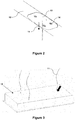
- the present invention provides a ceiling type range hood assembly (1) which is mounted on a ceiling (20) of a kitchen or built in furniture as shown in Fig. 1 .
- the assembly (1) is hung upon a support element (12) on or over the ceiling (20) by way of linear suspension means (11) such as wires or cables.
- the "ceiling type range hood” refers to a range hood which is installed in a stationary manner on the ceiling of a kitchen or within a ceiling part of a built in furniture in a kitchen such as an undercabinet hood.
- the range hood assembly (1) of the present invention is advantageous in many aspects as it can be installed by a single person easily without the risk of unintentional downfall endangering safety of the worker and furniture.
- This range hood assembly (1) provides also additional safety after installation, as the suspension means (11) facilitating installation also constitute additional means of fixation for the range hood body after installation.
- the suspension means (11) affixed to a support element (12) reinforce fixation of the range hood and eliminate any risk of downfall during usage especially in the case of earthquakes.
- a first end of the linear suspension means (11) is fixed to the support element (12) preferably with a plate (13) which is used to press and clamp said end of the suspension means (11) between the support element (12) and abovementioned plate (13).
- the plate (13) is preferably affixed to the support element (12) by way of screws (14).
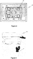
- the second ends of the suspensions means (11) are introduced into range hood body (15) as shown in Fig. 3 via through holes and they are then introduced into the hanging apparatus (16) within the range hood body (15).
- a plurality of hanging apparatus (16) are located in suitable positions within the range hood body (15) corresponding to the linear suspension means (11).
- four hanging apparatus (16) are arranged in close proximity of corners of the range hood body (15).
- the linear suspension means (11) passing through the hanging apparatus (16) are drooped downwards so that a technician may be pulling the suspension means (11) with one hand and lifting up the range hood body (15) with the other hand so that range hood body (15) can be elevated and brought closer to the ceiling (20).
- the technician repeats the above procedure on each of the linear suspension means (11) so that the range hood body (15) is eventually brought in place on the ceiling (20) gradually.
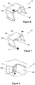
- FIGs 6, 7 and 8 show the hanging apparatus (16) in detail with and without the linear suspension means (11).
- the hanging apparatus (16) according to the present invention comprises a claw element (17) as shown in greater detail in Figures 9a, 9b and 9c .
- the claw element (17) is basically designed to have a body (171) through which a hole (173) is provided for passage of the linear suspension means (11). Said claw element (17) is embodied such that movement of the linear suspension means (11) passing through the hole (173) is normally allowed only in one direction (x 1 ) unless the push button (175) is activated by the technician.
- a plurality of gripping elements (174) are provided in the hole (173) which normally allow movement of the linear suspension means (11) only in one direction (x 1 ) and interlocking with the same when a force is applied in counter direction (x 2 ).
- push button (175) When push button (175) is activated, the gripping elements (174) are released so that linear suspension means (11) can move in any direction (x 1 , x 2 ) through the hole (173).
- the main body (171) of the claw element (17) may advantageously comprise a grooved surface as shown in Fig. 9a in order to be affixed to a surface (161) of the hanging apparatus (16), and optionally a nut (172) corresponding to the grooved surface may be provided for increasing durability of fixation mentioned above.
- the hanging apparatus (16) advantageously comprises an inner housing (163) which is generally formed by lateral walls (162) in order to accommodate excessive length of the linear suspension means (11). It is therefore possible to roll up said excessive material and hide it in the housing (163).
- this specific structure of the hanging apparatus (16) ensures avoidance of cable/wire mess within the range hood body (15) and eliminate any danger of contact with electricity.
- a lid (164) is also provided on one of the surfaces (161, 162) of the hanging apparatus (16) for accommodating the linear suspension means (11) safely for longer periods.
- the lid (164) can be affixed on said surfaces (161, 162) in a bendable manner without a need for additional fixations means such as a hinge.
- the present invention provides a method for installation of a ceiling type range hood assembly (1) comprising the steps of:
- the present invention provides a method for manufacturing a ceiling type range hood assembly (1) comprising the steps of:
Landscapes
- Engineering & Computer Science (AREA)
- General Engineering & Computer Science (AREA)
- Mechanical Engineering (AREA)
- Chemical & Material Sciences (AREA)
- Combustion & Propulsion (AREA)
- Ventilation (AREA)
Priority Applications (1)
| Application Number | Priority Date | Filing Date | Title |
|---|---|---|---|
| EP19219751.5A EP3842694A1 (fr) | 2019-12-27 | 2019-12-27 | Hotte aspirante de type au plafond ayant un système d'accrochage et d'installation amélioré |
Applications Claiming Priority (1)
| Application Number | Priority Date | Filing Date | Title |
|---|---|---|---|
| EP19219751.5A EP3842694A1 (fr) | 2019-12-27 | 2019-12-27 | Hotte aspirante de type au plafond ayant un système d'accrochage et d'installation amélioré |
Publications (1)
| Publication Number | Publication Date |
|---|---|
| EP3842694A1 true EP3842694A1 (fr) | 2021-06-30 |
Family
ID=69055694
Family Applications (1)
| Application Number | Title | Priority Date | Filing Date |
|---|---|---|---|
| EP19219751.5A Withdrawn EP3842694A1 (fr) | 2019-12-27 | 2019-12-27 | Hotte aspirante de type au plafond ayant un système d'accrochage et d'installation amélioré |
Country Status (1)
| Country | Link |
|---|---|
| EP (1) | EP3842694A1 (fr) |
Citations (9)
| Publication number | Priority date | Publication date | Assignee | Title |
|---|---|---|---|---|
| JPS4988554U (fr) * | 1972-11-09 | 1974-08-01 | ||
| US4878270A (en) * | 1989-05-09 | 1989-11-07 | Westerkamp Myron M | Rope tie-down apparatus |
| JPH0248737U (fr) * | 1988-09-30 | 1990-04-04 | ||
| KR20020083997A (ko) * | 2002-10-05 | 2002-11-04 | 이창덕 | 싱크대용 렌지후드 |
| KR200341153Y1 (ko) * | 2003-11-07 | 2004-02-11 | 강태선 | 리프팅수단을 갖춘 로스터용 배기장치 |
| EP2161507A2 (fr) | 2008-09-01 | 2010-03-10 | BSH Bosch und Siemens Hausgeräte GmbH | Dispositif d'aspiration de vapeurs, notamment hotte autonome pouvant être fixée au plafond, et agencement de module doté d'un tel dispositif d'aspiration de vapeurs |
| KR100961269B1 (ko) * | 2009-08-19 | 2010-06-03 | 박영인 | 연기배출용 후드의 높이조절구 고정장치 |
| WO2011063969A1 (fr) | 2009-11-26 | 2011-06-03 | Faber S.P.A. | Unité hotte pourvue d'un dispositif de soulèvement/abaissement |
| DE102017104198A1 (de) * | 2017-03-01 | 2018-09-06 | Miele & Cie. Kg | Deckenhaltevorrichtung zur Arretierung einer Dunstabzugseinheit und Dunstabzugseinheit zum Absaugen von Wrasen |
-
2019
- 2019-12-27 EP EP19219751.5A patent/EP3842694A1/fr not_active Withdrawn
Patent Citations (9)
| Publication number | Priority date | Publication date | Assignee | Title |
|---|---|---|---|---|
| JPS4988554U (fr) * | 1972-11-09 | 1974-08-01 | ||
| JPH0248737U (fr) * | 1988-09-30 | 1990-04-04 | ||
| US4878270A (en) * | 1989-05-09 | 1989-11-07 | Westerkamp Myron M | Rope tie-down apparatus |
| KR20020083997A (ko) * | 2002-10-05 | 2002-11-04 | 이창덕 | 싱크대용 렌지후드 |
| KR200341153Y1 (ko) * | 2003-11-07 | 2004-02-11 | 강태선 | 리프팅수단을 갖춘 로스터용 배기장치 |
| EP2161507A2 (fr) | 2008-09-01 | 2010-03-10 | BSH Bosch und Siemens Hausgeräte GmbH | Dispositif d'aspiration de vapeurs, notamment hotte autonome pouvant être fixée au plafond, et agencement de module doté d'un tel dispositif d'aspiration de vapeurs |
| KR100961269B1 (ko) * | 2009-08-19 | 2010-06-03 | 박영인 | 연기배출용 후드의 높이조절구 고정장치 |
| WO2011063969A1 (fr) | 2009-11-26 | 2011-06-03 | Faber S.P.A. | Unité hotte pourvue d'un dispositif de soulèvement/abaissement |
| DE102017104198A1 (de) * | 2017-03-01 | 2018-09-06 | Miele & Cie. Kg | Deckenhaltevorrichtung zur Arretierung einer Dunstabzugseinheit und Dunstabzugseinheit zum Absaugen von Wrasen |
Similar Documents
| Publication | Publication Date | Title |
|---|---|---|
| CN102639815B (zh) | 电缆支承挂钩 | |
| EP1052753A2 (fr) | Barre de suspension et agencement d'attache de fixation | |
| WO2017006835A1 (fr) | Dispositif de meuble avec plateau réglable en hauteur | |
| EP2327936A1 (fr) | Hotte mobile d'évacuation des fumées | |
| CN108458470B (zh) | 安装装置和空调系统 | |
| EP1597182A4 (fr) | Support integre pour machine d'ascenseur, reas et terminaisons | |
| KR20130136951A (ko) | 개방형 케이블행거용 취부장치 | |
| KR20250029087A (ko) | 설치 및 분리가 용이한 완철용 브라켓 | |
| JP6655483B2 (ja) | 天板昇降方式の什器装置 | |
| JP2016086909A (ja) | 天板昇降式デスク | |
| JP6504690B2 (ja) | 天板昇降式デスク | |
| US5141550A (en) | Positioning device for glass bending oven | |
| JP2008152186A (ja) | 薄型表示装置の固定装置の構造、及び薄型表示装置の設置作業に利用する設置装置の構造 | |
| EP3467386B1 (fr) | Dispositif formant hotte aspirante et procédé de montage d'un dispositif formant hotte aspirante | |
| JP2004141517A (ja) | 昇降装置と昇降操作方法 | |
| EP1453398B1 (fr) | Lampe et table ("lamp 'n' table) | |
| JP7498441B1 (ja) | エレベータ内の電気器具の操作具及び操作方法 | |
| CN108507148B (zh) | 安装机构及具有其的空调器 | |
| JP7480898B1 (ja) | エレベータ用揚重機の支持装置の固定方法、ガイド装置及び支持装置 | |
| JP7362022B1 (ja) | エレベータ用揚重機の支持装置及びその固定方法 | |
| JP6901917B2 (ja) | 消火栓装置 | |
| KR102698976B1 (ko) | 안전기능 탑재 다기능 건축물용 전선 지지기구 | |
| KR102894525B1 (ko) | 가공 배전라인 지지기구 | |
| CN108397896B (zh) | 安装装置和空调系统 | |
| CN211813165U (zh) | 一种便于检修的烟感探测装置 |
Legal Events
| Date | Code | Title | Description |
|---|---|---|---|
| PUAI | Public reference made under article 153(3) epc to a published international application that has entered the european phase |
Free format text: ORIGINAL CODE: 0009012 |
|
| STAA | Information on the status of an ep patent application or granted ep patent |
Free format text: STATUS: THE APPLICATION HAS BEEN PUBLISHED |
|
| AK | Designated contracting states |
Kind code of ref document: A1 Designated state(s): AL AT BE BG CH CY CZ DE DK EE ES FI FR GB GR HR HU IE IS IT LI LT LU LV MC MK MT NL NO PL PT RO RS SE SI SK SM TR |
|
| STAA | Information on the status of an ep patent application or granted ep patent |
Free format text: STATUS: REQUEST FOR EXAMINATION WAS MADE |
|
| 17P | Request for examination filed |
Effective date: 20211028 |
|
| RBV | Designated contracting states (corrected) |
Designated state(s): AL AT BE BG CH CY CZ DE DK EE ES FI FR GB GR HR HU IE IS IT LI LT LU LV MC MK MT NL NO PL PT RO RS SE SI SK SM TR |
|
| STAA | Information on the status of an ep patent application or granted ep patent |
Free format text: STATUS: EXAMINATION IS IN PROGRESS |
|
| 17Q | First examination report despatched |
Effective date: 20230315 |
|
| STAA | Information on the status of an ep patent application or granted ep patent |
Free format text: STATUS: THE APPLICATION IS DEEMED TO BE WITHDRAWN |
|
| 18D | Application deemed to be withdrawn |
Effective date: 20230726 |