EP3842736A1 - Procédé, système et dispositif de mesure de volume, et support d'informations lisible par ordinateur - Google Patents
Procédé, système et dispositif de mesure de volume, et support d'informations lisible par ordinateur Download PDFInfo
- Publication number
- EP3842736A1 EP3842736A1 EP19866397.3A EP19866397A EP3842736A1 EP 3842736 A1 EP3842736 A1 EP 3842736A1 EP 19866397 A EP19866397 A EP 19866397A EP 3842736 A1 EP3842736 A1 EP 3842736A1
- Authority
- EP
- European Patent Office
- Prior art keywords
- measured
- information
- target
- measurement
- volume
- Prior art date
- Legal status (The legal status is an assumption and is not a legal conclusion. Google has not performed a legal analysis and makes no representation as to the accuracy of the status listed.)
- Withdrawn
Links
Images


Classifications
-
- G—PHYSICS
- G01—MEASURING; TESTING
- G01B—MEASURING LENGTH, THICKNESS OR SIMILAR LINEAR DIMENSIONS; MEASURING ANGLES; MEASURING AREAS; MEASURING IRREGULARITIES OF SURFACES OR CONTOURS
- G01B5/00—Measuring arrangements characterised by the use of mechanical techniques
- G01B5/0021—Measuring arrangements characterised by the use of mechanical techniques for measuring the volumetric dimension of an object
-
- G—PHYSICS
- G01—MEASURING; TESTING
- G01B—MEASURING LENGTH, THICKNESS OR SIMILAR LINEAR DIMENSIONS; MEASURING ANGLES; MEASURING AREAS; MEASURING IRREGULARITIES OF SURFACES OR CONTOURS
- G01B11/00—Measuring arrangements characterised by the use of optical techniques
-
- G—PHYSICS
- G01—MEASURING; TESTING
- G01B—MEASURING LENGTH, THICKNESS OR SIMILAR LINEAR DIMENSIONS; MEASURING ANGLES; MEASURING AREAS; MEASURING IRREGULARITIES OF SURFACES OR CONTOURS
- G01B11/00—Measuring arrangements characterised by the use of optical techniques
- G01B11/24—Measuring arrangements characterised by the use of optical techniques for measuring contours or curvatures
-
- G—PHYSICS
- G06—COMPUTING OR CALCULATING; COUNTING
- G06T—IMAGE DATA PROCESSING OR GENERATION, IN GENERAL
- G06T7/00—Image analysis
- G06T7/60—Analysis of geometric attributes
- G06T7/62—Analysis of geometric attributes of area, perimeter, diameter or volume
-
- G—PHYSICS
- G01—MEASURING; TESTING
- G01B—MEASURING LENGTH, THICKNESS OR SIMILAR LINEAR DIMENSIONS; MEASURING ANGLES; MEASURING AREAS; MEASURING IRREGULARITIES OF SURFACES OR CONTOURS
- G01B11/00—Measuring arrangements characterised by the use of optical techniques
- G01B11/02—Measuring arrangements characterised by the use of optical techniques for measuring length, width or thickness
- G01B11/022—Measuring arrangements characterised by the use of optical techniques for measuring length, width or thickness by means of tv-camera scanning
-
- G—PHYSICS
- G01—MEASURING; TESTING
- G01B—MEASURING LENGTH, THICKNESS OR SIMILAR LINEAR DIMENSIONS; MEASURING ANGLES; MEASURING AREAS; MEASURING IRREGULARITIES OF SURFACES OR CONTOURS
- G01B11/00—Measuring arrangements characterised by the use of optical techniques
- G01B11/02—Measuring arrangements characterised by the use of optical techniques for measuring length, width or thickness
- G01B11/024—Measuring arrangements characterised by the use of optical techniques for measuring length, width or thickness by means of diode-array scanning
-
- G—PHYSICS
- G01—MEASURING; TESTING
- G01B—MEASURING LENGTH, THICKNESS OR SIMILAR LINEAR DIMENSIONS; MEASURING ANGLES; MEASURING AREAS; MEASURING IRREGULARITIES OF SURFACES OR CONTOURS
- G01B11/00—Measuring arrangements characterised by the use of optical techniques
- G01B11/22—Measuring arrangements characterised by the use of optical techniques for measuring depth
-
- G—PHYSICS
- G01—MEASURING; TESTING
- G01B—MEASURING LENGTH, THICKNESS OR SIMILAR LINEAR DIMENSIONS; MEASURING ANGLES; MEASURING AREAS; MEASURING IRREGULARITIES OF SURFACES OR CONTOURS
- G01B11/00—Measuring arrangements characterised by the use of optical techniques
- G01B11/24—Measuring arrangements characterised by the use of optical techniques for measuring contours or curvatures
- G01B11/25—Measuring arrangements characterised by the use of optical techniques for measuring contours or curvatures by projecting a pattern, e.g. one or more lines, moiré fringes on the object
-
- G—PHYSICS
- G06—COMPUTING OR CALCULATING; COUNTING
- G06T—IMAGE DATA PROCESSING OR GENERATION, IN GENERAL
- G06T17/00—Three-dimensional [3D] modelling for computer graphics
-
- G—PHYSICS
- G06—COMPUTING OR CALCULATING; COUNTING
- G06T—IMAGE DATA PROCESSING OR GENERATION, IN GENERAL
- G06T7/00—Image analysis
- G06T7/0002—Inspection of images, e.g. flaw detection
- G06T7/0004—Industrial image inspection
-
- G—PHYSICS
- G06—COMPUTING OR CALCULATING; COUNTING
- G06T—IMAGE DATA PROCESSING OR GENERATION, IN GENERAL
- G06T7/00—Image analysis
- G06T7/10—Segmentation; Edge detection
- G06T7/11—Region-based segmentation
-
- G—PHYSICS
- G06—COMPUTING OR CALCULATING; COUNTING
- G06T—IMAGE DATA PROCESSING OR GENERATION, IN GENERAL
- G06T7/00—Image analysis
- G06T7/10—Segmentation; Edge detection
- G06T7/13—Edge detection
-
- G—PHYSICS
- G06—COMPUTING OR CALCULATING; COUNTING
- G06T—IMAGE DATA PROCESSING OR GENERATION, IN GENERAL
- G06T7/00—Image analysis
- G06T7/50—Depth or shape recovery
- G06T7/521—Depth or shape recovery from laser ranging, e.g. using interferometry; from the projection of structured light
-
- G—PHYSICS
- G06—COMPUTING OR CALCULATING; COUNTING
- G06T—IMAGE DATA PROCESSING OR GENERATION, IN GENERAL
- G06T7/00—Image analysis
- G06T7/50—Depth or shape recovery
- G06T7/55—Depth or shape recovery from multiple images
- G06T7/593—Depth or shape recovery from multiple images from stereo images
-
- H—ELECTRICITY
- H04—ELECTRIC COMMUNICATION TECHNIQUE
- H04N—PICTORIAL COMMUNICATION, e.g. TELEVISION
- H04N13/00—Stereoscopic video systems; Multi-view video systems; Details thereof
- H04N13/20—Image signal generators
- H04N13/204—Image signal generators using stereoscopic image cameras
- H04N13/239—Image signal generators using stereoscopic image cameras using two two-dimensional [2D] image sensors having a relative position equal to or related to the interocular distance
-
- H—ELECTRICITY
- H04—ELECTRIC COMMUNICATION TECHNIQUE
- H04N—PICTORIAL COMMUNICATION, e.g. TELEVISION
- H04N13/00—Stereoscopic video systems; Multi-view video systems; Details thereof
- H04N13/20—Image signal generators
- H04N13/204—Image signal generators using stereoscopic image cameras
- H04N13/254—Image signal generators using stereoscopic image cameras in combination with electromagnetic radiation sources for illuminating objects
-
- G—PHYSICS
- G06—COMPUTING OR CALCULATING; COUNTING
- G06T—IMAGE DATA PROCESSING OR GENERATION, IN GENERAL
- G06T2207/00—Indexing scheme for image analysis or image enhancement
- G06T2207/10—Image acquisition modality
- G06T2207/10028—Range image; Depth image; 3D point clouds
-
- G—PHYSICS
- G06—COMPUTING OR CALCULATING; COUNTING
- G06T—IMAGE DATA PROCESSING OR GENERATION, IN GENERAL
- G06T2207/00—Indexing scheme for image analysis or image enhancement
- G06T2207/20—Special algorithmic details
- G06T2207/20021—Dividing image into blocks, subimages or windows
-
- G—PHYSICS
- G06—COMPUTING OR CALCULATING; COUNTING
- G06T—IMAGE DATA PROCESSING OR GENERATION, IN GENERAL
- G06T2207/00—Indexing scheme for image analysis or image enhancement
- G06T2207/30—Subject of image; Context of image processing
- G06T2207/30108—Industrial image inspection
- G06T2207/30112—Baggage; Luggage; Suitcase
Definitions
- the present patent application relates to the field of logistics, and in particular to a volume measurement method and system, an apparatus and a computer-readable storage medium.
- volume measurement is the basis of goods circulation and transportation. It is very important to choose the right transportation vehicles, ships, and airplanes for the right volume.
- most of the object volume measuring work is still done by the traditional method using the tape measure.
- the existing automated volume measurement technologies mostly use laser scanners and multi-vision fusion technology.
- a typical solution is to use one laser scanning emitter and four industrial cameras that are distributed around the object to be measured, and the size is measured by using the camera to capture the line laser emitted by the laser device.
- such a measurement method is more accurate and efficient than manual measurement, it requires a large area. Since the industrial camera must cover the viewing field of the object to be measured, the volume of which is almost twice that of the object to be measured. Therefore, the whole set of equipment also needs a stable bracket to fix it.
- such equipment is relatively complicated and must have expensive laser device and industrial cameras. The complicated system thus has high requirements for the hardware of the measurement equipment and the splicing and processing capabilities of the vision system.
- the object of the present patent application is to provide a volume measurement method and system.
- a volume measurement method which comprises the following steps:
- the 3D vision system comprises a first camera, a second camera, and a structured laser emitter;
- the structured laser emitter is configured to collect a first information of a measurement area when there is no object to be measured under a current viewing field, and judge whether a depth change of the measurement area exceeds a threshold according to laser grids; if it exceeds the threshold, determine that there is an object to be measured in the measurement area, drive the first camera to collect the first depth image of the measurement area, and drive the second camera to perform grayscale processing on the first depth image to generate the first depth image information.
- the outer contour of the object to be measured is matched with a standard double-layer calibration target of the 3D vision system based on an arrangement distance between the first camera and the second camera to obtain a size of the outer contour of the object to be measured.
- Target org represents a boundary size of one of divided blocks
- Target new represents a boundary size of a corresponding newly divided block after depth change
- Distance (Obstacles, Robot) is a function for calculating a depth and a size of a divided block
- w 1 and w 2 are weight coefficients.
- H org is a basic height value of the object to be measured in an image before block division
- H is a height value of a divided block in the outer contour area of the object to be measured in an image.
- a volume measurement system which comprises:
- the 3D vision system comprises a first camera, a second camera, and a structured laser emitter;
- the structured laser emitter is configured to collect a first information of a measurement area when there is no object to be measured under a current viewing field, and judge whether a depth change of the measurement area exceeds a threshold according to laser grids; if it exceeds the threshold, determine that there is an object to be measured in the measurement area, drive the first camera to collect the first depth image of the measurement area, and drive the second camera to perform grayscale processing on the first depth image to generate the first depth image information.
- the unit for acquiring a target of object to be measured is further configured to match the outer contour of the object to be measured with a standard double-layer calibration target of the 3D vision system based on an arrangement distance between the first camera and the second camera to obtain a size of the outer contour of the object to be measured.
- the 3D vision system is located right above the measurement area or located obliquely above the object to be measured in the measurement area.
- Target org represents a boundary size of one of divided blocks
- Target new represents a boundary size of a corresponding newly divided block after depth change
- Distance (Obstacles, Robot) is a function for calculating a depth and a size of a divided block
- w 1 and w 2 are weight coefficients.
- H org is a basic height value of the object to be measured in an image before block division
- H is a height value of a divided block in the outer contour area of the object to be measured in an image.
- an apparatus which comprises:
- a computer-readable storage medium having a computer program stored thereon, wherein when the computer program is executed by a processor, the method described in any of the above items is implemented.
- the present embodiment provides a volume measurement system, comprising:
- the 3D vision system comprises a first camera, a second camera, and a structured laser emitter.
- the structured laser emitter is configured to collect a first information of a measurement area when there is no object to be measured under a current viewing field, and judge whether a depth change of the measurement area exceeds a threshold according to laser grids; if it exceeds the threshold, determine that there is an object to be measured in the measurement area, drive the first camera to collect the first depth image of the measurement area, and drive the second camera to perform grayscale processing on the first depth image to generate the first depth image information.
- the unit for acquiring a target of object to be measured is further configured to match the outer contour of the object to be measured with a standard double-layer calibration target of the 3D vision system based on an arrangement distance between the first camera and the second camera to obtain a size of the outer contour of the object to be measured.
- the first camera is specifically a color camera used to take a full picture of the object to be measured
- the second camera is specifically a black-and-white camera mainly used for gray processing.
- the two cameras are installed with a fixed distance between them, and the infrared laser detected by them can assist measuring distance.
- the structured laser emitter is specifically a structured laser emitter with coding characteristics, and is the most important direct sensor for measuring distance.
- the coding characteristic can effectively avoid the interference of visible light and other light beams of the same type.
- the 3D vision system is located right above the measurement area or obliquely above the object to be measured in the measurement area.
- Target org represents a boundary size of one of divided blocks
- Target new represents a boundary size of a corresponding newly divided block after depth change
- Distance (Obstacles, Robot) is a function for calculating a depth and a size of a divided block
- w 1 and w 2 are weight coefficients.
- H org is a basic height value of the object to be measured in an image before block division
- H is a height value of a divided block in the outer contour area of the object to be measured in an image.
- the present embodiment provides a volume measurement method. As shown in FIG. 1 , it comprises the following steps: S1: collecting a first information of a measurement area when there is no object to be measured and a first depth image information of the measurement area when there is an object to be measured under a current viewing angle based on a 3D vision system.
- the 3D vision system is located above the measurement area. Specifically, it is located right above the measurement area or obliquely above the object to be measured in the measurement area.
- the 3D vision system comprises a first camera, a second camera, and a structured laser emitter.
- the structured laser emitter is configured to collect a first information of a measurement area when there is no object to be measured under a current viewing field, and judge whether a depth change of the measurement area exceeds a threshold according to laser grids; if it exceeds the threshold, determine that there is an object to be measured in the measurement area, drive the first camera to collect the first depth image of the measurement area, and drive the second camera to perform grayscale processing on the first depth image to generate the first depth image information.
- S2 identifying an outer contour of the object to be measured by comparing gray values of the first information and the first depth image information collected under different viewing angles to obtain a first depth information of the outer contour of the object to be measured, and filling in an area defined by the outer contour of the object to be measured to obtain a target of object to be measured and size information of the target of object to be measured.
- the outer contour of the object to be measured is matched with a standard double-layer calibration target of the 3D vision system based on an arrangement distance between the first camera and the second camera to obtain a size of the outer contour of the object to be measured.
- S3 performing block division on an outer contour area of the object to be measured according to a preset relationship between the first depth information and divided blocks to generate block information.
- Target org represents a boundary size of one of divided blocks
- Target new represents a boundary size of a corresponding newly divided block after depth change
- Distance (Obstacles, Robot) is a function for calculating a depth and a size of a divided block
- w 1 and w 2 are weight coefficients.
- S4 obtaining a volume of the object to be measured according to a preset relationship among the block information, the size information of the target of object to be measured, and a volume of the object to be measured.
- H org is a basic height value of the object to be measured in an image before block division
- H is a height value of a divided block in the outer contour area of the object to be measured in an image.
- the 3D vision system is specifically a set of integrated 3D vision sampling modules.
- the sampling modules comprise a color camera, a black-and-white camera, and a structured laser emitter with coding characteristics.
- the original parts used in the modules are available in the current market. For example, cameras and laser modules commonly used in the mobile phone industry can be used.
- the overall module is very economical.
- the layout of the 3D vision sampling module has been designed in multiple dimensions. The most common layout is to place it right above the object to be measured, as shown in FIG. 2 .
- the advantage of such a layout is that a large viewing field space can be covered using a single 3D vision module. Combined with coded structured light, the measurement accuracy can be maximized.
- the top installation occupies a very small space, and can be realized using a pillar suspended from the ceiling. Such an installation method completely releases the bottom space and the net space is unprecedentedly huge.
- the core of the volume measurement method of the present patent application is a volume measurement method combining 3D vision with real physical space.
- the specific steps are as follows.
- the depth ray model of the current viewing field area is modeled, a low-power mode is used to encode the laser grids in low latitude, and the measurement area defined by the viewing field is grayscale processed.
- the measurement system is turned on to perform laser speckle in high latitude and grid laser transformation to increase the area scanning frequency.
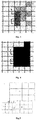
- the boundary of the object to be measured is scanned, and the largest outer contour of the object to be measured is determined by comparing the gray value changes before and after the object entered. Then the area contained in the edge area is filled in. Based on this information, the largest possible object volume information can be obtained, as shown in FIG. 3 to FIG. 4 .
- the maximum outer contour of the object to be measured is the size of outer edges, which can be directly obtained by matching the standard double-layer calibration target.
- the purpose of determining this size is to determine the maximum boundary of divided blocks.
- the calibration target calibrates the accuracy of two size at one time. According to a fixed depth, a zoom factor of the size accuracy is calculated in equal proportion. If the depth is greater, the measurement size is larger, and the error will also be larger, so the zoom ratio is used to reduce the error and needs to be calibrated before leaving the factory.
- the depth ray is based on the laser ranging sensor ToF technology, which detects whether there is an object in the area, and then turns on the camera to perform measurement, so as to avoid the excessive heat produced by the camera after long working hours.
- the ToF range sensor is set according to the parameters when there is no object. At this point, the camera sleeps and does not acquire images.
- the detection of the presence or absence of the object to be measured relies on encoded laser grid in low latitude checking whether there is a depth change in the measurement area.
- the outer contour of the object to be measured is divided into blocks.
- the block division is performed on the outer contour of the object to be measured obtained in step (1).
- the block division is made in a non-linear growth manner based on the depth information. The nonlinearity changes according to the distortion correction coefficient of the lens of camera.
- Target org represents a boundary size of a divided block (i.e., a boundary size of one of the blocks after division);
- Target new represents a boundary size of a newly divided block after depth change (i.e., a boundary size of a corresponding newly divided block after depth change);
- Distance (Obstacles, Robot) is a function for calculating a depth and a size of a divided block; w 1 and w 2 are weight coefficients. According to the difference caused by the block division, a new block has a new depth, and the depths of adjacent blocks are not the same.
- FIG. 5 An example of the blocks divided in this way is as shown in FIG. 5 .
- the depth information is filled in each block area, and the volume distribution is accurately measured. It can be concluded that in the part close to the camera, the block divided is large and the quantity of blocks is small; in the part far from the camera, the block divided is small and the quantity of blocks is large.
- the average value of the depth information is calculated.
- the volume of the object is the sum of the product of the average value of all blocks of the same size and the area occupied by the blocks of the same size.
- V w 1 ⁇ H org ⁇ ⁇ H ⁇ T arg et org T arg et new
- H org is a basic height value of the object to be measured in an image before block division
- H is a height value of a divided block in the outer contour area of the object to be measured in an image
- V is the total volume after measurement.
- the volume measurement method of the present patent application proposes a new and simple algorithm which is a defining and accurate measurement method. Compared with the point cloud and triangulation method, this method greatly improves the computing performance. Combined with the simple and compact space layout, a fast and accurate volume measurement function is realized.
- the present patent application may be used alone as a separate measurement system module. It may also combine the weighing system and the barcode scanning system in the logistics industry to output complete cargo information. This method effectively improves equipment performance and logistics capabilities, reduces complexity of equipment, and is easy to install and use.
- the volume measurement algorithm does not need to transform the two-dimensional coordinates in the vision system into real three-dimensional space coordinates, and can directly calculate the volume of the object to be measured using limited information, so the method is simple and practical.
- the present embodiment further provides an apparatus suitable for implementing the method according to the embodiments of the present application.
- the apparatus includes a computer system.
- the computer system includes a central processing unit (CPU) that performs a variety of appropriate actions and processes according to a program stored in a read only memory (ROM) or loaded from a storage section into a random access memory (RAM).
- ROM read only memory
- RAM random access memory
- various programs and data necessary for the operation of the device are also stored.
- the CPU, ROM, and RAM are connected to each other by a bus.
- An input/output (I/O) interface is also connected to the bus.
- the following components are connected to the I/O interface: an input section including a keyboard or a mouse or the like; an output section including a display such as a cathode ray tube (CRT) or a liquid crystal display (LCD), a storage section including a hard disk or the like, and a communication section including a network interface card such as a LAN card or a modem.
- the communication section performs communication processing via a network such as the Internet.
- the drive is also connected to the I/O interface as needed.
- a removable medium such as a magnetic disk, an optical disk, a magneto-optical disk or a semiconductor memory, is mounted on the drive as needed so that a computer program read out therefrom is installed into the storage section as needed.
- an embodiment of the present disclosure includes a computer program product comprising a computer program tangibly embodied on a machine-readable medium, and the computer program includes program code for executing the method of FIG. 1 .
- the computer program may be downloaded and installed from the network through the communication section, and/or installed from a removable medium.
- each block in the flowchart can represent a module, a part of program segment or code, wherein the module and the part of program segment or code include one or more executable instructions for performing stipulated logic functions.
- the functions indicated in the block can also take place in an order different from the one indicated in the drawings. For example, two successive blocks can be in fact executed in parallel or sometimes in a reverse order, which depends on the functions involved.
- each block in the flowchart and combinations of the blocks in the flowchart can be implemented by a hardware-based system exclusive for executing stipulated functions or actions, or by a combination of dedicated hardware and computer instructions.
- the units or modules described in the embodiments of the present application can be implemented in software or hardware.
- the units or modules described can also be provided in the processor.
- the names of these units or modules do not constitute a limitation on the units or modules themselves under certain circumstances.
- the present embodiment further provides a computer-readable storage medium.
- the computer-readable storage medium may be the computer-readable storage medium included in the system described in the foregoing embodiment. Alternatively, it may be computer-readable storage medium that exist separately and is not installed into any equipment.
- the computer-readable storage medium stores one or more programs, and the programs are executed by one or more processors to perform the volume measurement method described in the present application.
- the present embodiment is different from the first embodiment in that, the 3D vision acquiring module can be placed obliquely above the three-dimensional diagonal of the object to be measured. As shown in FIG. 6 , the observation angle of the camera can cover three main faces of the entire object to be measured. By solving the information of the three faces, more volume details can be obtained, and thus the measurement accuracy can be improved. Similarly, this installation method is simple and occupies a small space. A picture of the object to be measured can be taken while measuring the volume.
Landscapes
- Engineering & Computer Science (AREA)
- Physics & Mathematics (AREA)
- General Physics & Mathematics (AREA)
- Theoretical Computer Science (AREA)
- Computer Vision & Pattern Recognition (AREA)
- Geometry (AREA)
- Signal Processing (AREA)
- Multimedia (AREA)
- Optics & Photonics (AREA)
- Electromagnetism (AREA)
- Computer Graphics (AREA)
- Software Systems (AREA)
- Quality & Reliability (AREA)
- Length Measuring Devices By Optical Means (AREA)
Applications Claiming Priority (2)
| Application Number | Priority Date | Filing Date | Title |
|---|---|---|---|
| CN201811141066.7A CN109443196B (zh) | 2018-09-28 | 2018-09-28 | 一种体积测量方法及系统 |
| PCT/CN2019/090310 WO2020062918A1 (fr) | 2018-09-28 | 2019-06-06 | Procédé, système et dispositif de mesure de volume, et support d'informations lisible par ordinateur |
Publications (2)
| Publication Number | Publication Date |
|---|---|
| EP3842736A1 true EP3842736A1 (fr) | 2021-06-30 |
| EP3842736A4 EP3842736A4 (fr) | 2021-10-06 |
Family
ID=65544781
Family Applications (1)
| Application Number | Title | Priority Date | Filing Date |
|---|---|---|---|
| EP19866397.3A Withdrawn EP3842736A4 (fr) | 2018-09-28 | 2019-06-06 | Procédé, système et dispositif de mesure de volume, et support d'informations lisible par ordinateur |
Country Status (8)
| Country | Link |
|---|---|
| US (1) | US11436748B2 (fr) |
| EP (1) | EP3842736A4 (fr) |
| JP (1) | JP2022501603A (fr) |
| KR (1) | KR102559661B1 (fr) |
| CN (1) | CN109443196B (fr) |
| CA (1) | CA3114457C (fr) |
| MY (1) | MY209293A (fr) |
| WO (1) | WO2020062918A1 (fr) |
Cited By (1)
| Publication number | Priority date | Publication date | Assignee | Title |
|---|---|---|---|---|
| JP2023040777A (ja) * | 2021-09-10 | 2023-03-23 | 株式会社東芝 | 制御装置、制御方法およびプログラム |
Families Citing this family (19)
| Publication number | Priority date | Publication date | Assignee | Title |
|---|---|---|---|---|
| CN109443196B (zh) | 2018-09-28 | 2020-07-24 | 顺丰科技有限公司 | 一种体积测量方法及系统 |
| DE112019000125B4 (de) | 2018-10-30 | 2021-07-01 | Mujin, Inc. | Systeme, vorrichtungen und verfahren zur automatisierten verpackungsregistrierung |
| CN109916302B (zh) * | 2019-03-27 | 2020-11-20 | 青岛小鸟看看科技有限公司 | 一种载货箱体的体积测量方法和系统 |
| CN110017773B (zh) * | 2019-05-09 | 2021-12-17 | 福建(泉州)哈工大工程技术研究院 | 一种基于机器视觉的包裹体积测量方法 |
| CN111986250B (zh) * | 2019-05-22 | 2024-08-20 | 顺丰科技有限公司 | 物体体积测量方法、装置、测量设备及存储介质 |
| CN112150533B (zh) * | 2019-06-28 | 2024-11-29 | 顺丰科技有限公司 | 物体体积计算方法、装置、设备、及存储介质 |
| TWI738098B (zh) * | 2019-10-28 | 2021-09-01 | 阿丹電子企業股份有限公司 | 光學式體積測定裝置 |
| CN111561872B (zh) * | 2020-05-25 | 2022-05-13 | 中科微至智能制造科技江苏股份有限公司 | 基于散斑编码结构光的包裹体积测量方法、装置及系统 |
| CN112584015B (zh) * | 2020-12-02 | 2022-05-17 | 达闼机器人股份有限公司 | 物体探测方法、装置、存储介质和电子设备 |
| CN113313803B (zh) * | 2021-06-11 | 2024-04-19 | 梅卡曼德(北京)机器人科技有限公司 | 垛型分析方法、装置、计算设备及计算机存储介质 |
| US12544929B2 (en) | 2021-07-21 | 2026-02-10 | Mujin, Inc. | Robotic system with depth-based processing mechanism and methods for operating the same |
| US12290944B2 (en) * | 2021-08-09 | 2025-05-06 | Mujin, Inc. | Robotic system with image-based sizing mechanism and methods for operating the same |
| CN114494404B (zh) * | 2022-02-14 | 2024-07-23 | 云从科技集团股份有限公司 | 物体体积测量方法、系统、装置和介质 |
| CN114549513B (zh) * | 2022-03-02 | 2024-07-19 | 季华实验室 | 零件识别方法、装置、质检方法、电子设备及存储介质 |
| CN115235344B (zh) * | 2022-06-06 | 2023-08-01 | 苏州天准科技股份有限公司 | 基于涡旋光束的测量系统及高度测量方法 |
| CN116734945B (zh) * | 2023-06-16 | 2024-08-13 | 广东西克智能科技有限公司 | 一种基于光栅的规则箱体体积测量系统 |
| CN117073558B (zh) * | 2023-07-17 | 2025-07-04 | 华中科技大学 | 结合超分重建的电子封装基板翘曲检测方法及测量系统 |
| CN117782068B (zh) * | 2023-12-28 | 2025-10-24 | 中国科学院长春光学精密机械与物理研究所 | 基于图像处理的导航方法、装置、系统及存储介质 |
| CN117670979B (zh) * | 2024-02-01 | 2024-04-30 | 四川港投云港科技有限公司 | 一种基于固定点位单目相机的大宗货物体积测量方法 |
Family Cites Families (11)
| Publication number | Priority date | Publication date | Assignee | Title |
|---|---|---|---|---|
| JPH11211438A (ja) * | 1998-01-22 | 1999-08-06 | Komatsu Ltd | 荷台積載体積計測装置 |
| JP3803750B2 (ja) * | 2002-02-22 | 2006-08-02 | 防衛庁技術研究本部長 | 体積計測方法及び体積計測プログラム |
| JP4917983B2 (ja) | 2007-07-18 | 2012-04-18 | 大成建設株式会社 | 搬送量推定装置 |
| NO330423B1 (no) * | 2009-06-26 | 2011-04-11 | Storvik Aqua As | Anordning og fremgangsmate for fisketelling eller biomassebestemmelse |
| US8564534B2 (en) * | 2009-10-07 | 2013-10-22 | Microsoft Corporation | Human tracking system |
| CN104197834A (zh) * | 2014-09-04 | 2014-12-10 | 福建师范大学 | 一种非接触式复杂表面锥体体积测量系统及方法 |
| US10262222B2 (en) * | 2016-04-13 | 2019-04-16 | Sick Inc. | Method and system for measuring dimensions of a target object |
| CN107388960B (zh) * | 2016-05-16 | 2019-10-22 | 杭州海康机器人技术有限公司 | 一种确定物体体积的方法及装置 |
| US10630959B2 (en) * | 2016-07-12 | 2020-04-21 | Datalogic Usa, Inc. | System and method for object counting and tracking |
| CN106839995B (zh) * | 2017-01-22 | 2019-11-05 | 南京景曜智能科技有限公司 | 一种物品三维尺寸检测装置及检测方法 |
| CN109443196B (zh) | 2018-09-28 | 2020-07-24 | 顺丰科技有限公司 | 一种体积测量方法及系统 |
-
2018
- 2018-09-28 CN CN201811141066.7A patent/CN109443196B/zh active Active
-
2019
- 2019-06-06 MY MYPI2021001556A patent/MY209293A/en unknown
- 2019-06-06 EP EP19866397.3A patent/EP3842736A4/fr not_active Withdrawn
- 2019-06-06 KR KR1020217010703A patent/KR102559661B1/ko active Active
- 2019-06-06 JP JP2021517211A patent/JP2022501603A/ja active Pending
- 2019-06-06 US US17/280,790 patent/US11436748B2/en active Active
- 2019-06-06 CA CA3114457A patent/CA3114457C/fr active Active
- 2019-06-06 WO PCT/CN2019/090310 patent/WO2020062918A1/fr not_active Ceased
Cited By (1)
| Publication number | Priority date | Publication date | Assignee | Title |
|---|---|---|---|---|
| JP2023040777A (ja) * | 2021-09-10 | 2023-03-23 | 株式会社東芝 | 制御装置、制御方法およびプログラム |
Also Published As
| Publication number | Publication date |
|---|---|
| CA3114457A1 (fr) | 2020-04-02 |
| WO2020062918A1 (fr) | 2020-04-02 |
| KR102559661B1 (ko) | 2023-07-26 |
| US20220012907A1 (en) | 2022-01-13 |
| CN109443196B (zh) | 2020-07-24 |
| JP2022501603A (ja) | 2022-01-06 |
| US11436748B2 (en) | 2022-09-06 |
| EP3842736A4 (fr) | 2021-10-06 |
| MY209293A (en) | 2025-07-01 |
| KR20210080368A (ko) | 2021-06-30 |
| CN109443196A (zh) | 2019-03-08 |
| CA3114457C (fr) | 2024-11-12 |
Similar Documents
| Publication | Publication Date | Title |
|---|---|---|
| US11436748B2 (en) | Volume measurement method and system, apparatus and computer-readable storage medium | |
| EP3491332B1 (fr) | Estimation d'une carte de réflectivité à partir de systèmes de lumière structurée basée sur des points | |
| US9787960B2 (en) | Image processing apparatus, image processing system, image processing method, and computer program | |
| CN112883955A (zh) | 货架布局检测方法、装置及计算机可读存储介质 | |
| CN115410167A (zh) | 目标检测与语义分割方法、装置、设备及存储介质 | |
| CN110095062A (zh) | 一种物体体积参数测量方法、装置及设备 | |
| CN116245937A (zh) | 货物堆垛的堆高预测方法及装置、设备、存储介质 | |
| CN111383257A (zh) | 一种车厢装卸率确定方法和装置 | |
| CN111750804A (zh) | 一种物体测量的方法及设备 | |
| CN113538555A (zh) | 基于规则箱体的体积测量方法、系统、设备及存储介质 | |
| CN120506938B (zh) | 融合激光视觉的地图动态构建方法及系统 | |
| CN107451976A (zh) | 一种图像处理方法及装置 | |
| CN109766896B (zh) | 一种相似度度量方法、装置、设备和存储介质 | |
| Ladplee et al. | Volumetric measurement of rectangular parcel box using LiDar depth camera for dimensioning and 3D bin packing applications | |
| CN116358486A (zh) | 基于单目相机的目标测距方法、装置及介质 | |
| Han et al. | An automatic measurement method for hull weld seam dimensions based on 3D laser scanning | |
| CN115836322B (zh) | 图像裁剪方法与装置、电子设备及存储介质 | |
| CN121391769A (zh) | 一种基于图像与点云融合的混凝土裂缝智能识别分析平台 | |
| CN116363323A (zh) | 栅格地图动态目标去除方法、系统、电子设备及存储介质 | |
| CN113538553B (zh) | 基于规则箱体的体积测量装置 | |
| CN116912645B (zh) | 融合纹理和几何特征的三维目标检测方法及装置 | |
| CN118115765A (zh) | 一种图像匹配方法、装置、设备及存储介质 | |
| CN116468787A (zh) | 一种叉车托盘的位置信息提取方法、装置和域控制器 | |
| CN119091076B (zh) | 一种三维建筑模型的生成方法、系统、设备及存储介质 | |
| CN116206303B (zh) | 3d目标检测方法、装置及设备 |
Legal Events
| Date | Code | Title | Description |
|---|---|---|---|
| STAA | Information on the status of an ep patent application or granted ep patent |
Free format text: STATUS: THE INTERNATIONAL PUBLICATION HAS BEEN MADE |
|
| PUAI | Public reference made under article 153(3) epc to a published international application that has entered the european phase |
Free format text: ORIGINAL CODE: 0009012 |
|
| STAA | Information on the status of an ep patent application or granted ep patent |
Free format text: STATUS: REQUEST FOR EXAMINATION WAS MADE |
|
| 17P | Request for examination filed |
Effective date: 20210326 |
|
| AK | Designated contracting states |
Kind code of ref document: A1 Designated state(s): AL AT BE BG CH CY CZ DE DK EE ES FI FR GB GR HR HU IE IS IT LI LT LU LV MC MK MT NL NO PL PT RO RS SE SI SK SM TR |
|
| REG | Reference to a national code |
Ref country code: DE Ref legal event code: R079 Free format text: PREVIOUS MAIN CLASS: G01B0011000000 Ipc: G01B0005000000 |
|
| A4 | Supplementary search report drawn up and despatched |
Effective date: 20210903 |
|
| RIC1 | Information provided on ipc code assigned before grant |
Ipc: G01B 11/25 20060101ALI20210830BHEP Ipc: G01B 5/00 20060101AFI20210830BHEP |
|
| DAV | Request for validation of the european patent (deleted) | ||
| DAX | Request for extension of the european patent (deleted) | ||
| STAA | Information on the status of an ep patent application or granted ep patent |
Free format text: STATUS: THE APPLICATION IS DEEMED TO BE WITHDRAWN |
|
| 18D | Application deemed to be withdrawn |
Effective date: 20240103 |