EP3843068A1 - Dispositif de réglage de surface incurvée et écran d'affichage à del - Google Patents
Dispositif de réglage de surface incurvée et écran d'affichage à del Download PDFInfo
- Publication number
- EP3843068A1 EP3843068A1 EP18897864.7A EP18897864A EP3843068A1 EP 3843068 A1 EP3843068 A1 EP 3843068A1 EP 18897864 A EP18897864 A EP 18897864A EP 3843068 A1 EP3843068 A1 EP 3843068A1
- Authority
- EP
- European Patent Office
- Prior art keywords
- locking
- arc
- curved surface
- shaped sliding
- rotation stop
- Prior art date
- Legal status (The legal status is an assumption and is not a legal conclusion. Google has not performed a legal analysis and makes no representation as to the accuracy of the status listed.)
- Granted
Links
Images



Classifications
-
- G—PHYSICS
- G06—COMPUTING OR CALCULATING; COUNTING
- G06F—ELECTRIC DIGITAL DATA PROCESSING
- G06F1/00—Details not covered by groups G06F3/00 - G06F13/00 and G06F21/00
- G06F1/16—Constructional details or arrangements
- G06F1/18—Packaging or power distribution
- G06F1/181—Enclosures
-
- F—MECHANICAL ENGINEERING; LIGHTING; HEATING; WEAPONS; BLASTING
- F16—ENGINEERING ELEMENTS AND UNITS; GENERAL MEASURES FOR PRODUCING AND MAINTAINING EFFECTIVE FUNCTIONING OF MACHINES OR INSTALLATIONS; THERMAL INSULATION IN GENERAL
- F16M—FRAMES, CASINGS OR BEDS OF ENGINES, MACHINES OR APPARATUS, NOT SPECIFIC TO ENGINES, MACHINES OR APPARATUS PROVIDED FOR ELSEWHERE; STANDS; SUPPORTS
- F16M11/00—Stands or trestles as supports for apparatus or articles placed thereon ; Stands for scientific apparatus such as gravitational force meters
- F16M11/02—Heads
- F16M11/04—Means for attachment of apparatus; Means allowing adjustment of the apparatus relatively to the stand
- F16M11/06—Means for attachment of apparatus; Means allowing adjustment of the apparatus relatively to the stand allowing pivoting
- F16M11/08—Means for attachment of apparatus; Means allowing adjustment of the apparatus relatively to the stand allowing pivoting around a vertical axis, e.g. panoramic heads
-
- G—PHYSICS
- G09—EDUCATION; CRYPTOGRAPHY; DISPLAY; ADVERTISING; SEALS
- G09F—DISPLAYING; ADVERTISING; SIGNS; LABELS OR NAME-PLATES; SEALS
- G09F9/00—Indicating arrangements for variable information in which the information is built-up on a support by selection or combination of individual elements
- G09F9/30—Indicating arrangements for variable information in which the information is built-up on a support by selection or combination of individual elements in which the desired character or characters are formed by combining individual elements
- G09F9/301—Indicating arrangements for variable information in which the information is built-up on a support by selection or combination of individual elements in which the desired character or characters are formed by combining individual elements flexible foldable or roll-able electronic displays, e.g. thin LCD, OLED
-
- G—PHYSICS
- G09—EDUCATION; CRYPTOGRAPHY; DISPLAY; ADVERTISING; SEALS
- G09F—DISPLAYING; ADVERTISING; SIGNS; LABELS OR NAME-PLATES; SEALS
- G09F9/00—Indicating arrangements for variable information in which the information is built-up on a support by selection or combination of individual elements
- G09F9/30—Indicating arrangements for variable information in which the information is built-up on a support by selection or combination of individual elements in which the desired character or characters are formed by combining individual elements
- G09F9/33—Indicating arrangements for variable information in which the information is built-up on a support by selection or combination of individual elements in which the desired character or characters are formed by combining individual elements being semiconductor devices, e.g. diodes
-
- F—MECHANICAL ENGINEERING; LIGHTING; HEATING; WEAPONS; BLASTING
- F16—ENGINEERING ELEMENTS AND UNITS; GENERAL MEASURES FOR PRODUCING AND MAINTAINING EFFECTIVE FUNCTIONING OF MACHINES OR INSTALLATIONS; THERMAL INSULATION IN GENERAL
- F16M—FRAMES, CASINGS OR BEDS OF ENGINES, MACHINES OR APPARATUS, NOT SPECIFIC TO ENGINES, MACHINES OR APPARATUS PROVIDED FOR ELSEWHERE; STANDS; SUPPORTS
- F16M2200/00—Details of stands or supports
- F16M2200/02—Locking means
- F16M2200/021—Locking means for rotational movement
- F16M2200/024—Locking means for rotational movement by positive interaction, e.g. male-female connections
Definitions
- the invention belongs to the technical field of curved surface adjustment of LED display screens, and relates to a curved surface adjustment device and LED display screen.
- LED display screen generally realizes the curved display of the screen body through the trimming of the display screen box body and arcuate lock.
- the above methods require customization of a specific steel frame structure, which is large in work quantity and high in cost. Different steel structures need to be customized for different radii of curved surfaces, which has poor universality, poor surface smoothness, large curved surface radius and unsatisfactory curved display effect.
- the technical problem to be solved by the invention is to provide a curved surface adjustment device and an LED display screen aiming at the existing technical problem of poor surface smoothness of the screen body.
- the embodiment of the present invention provides a curved surface adjustment device, comprising: an angle rotating assembly and a locking assembly, wherein the angle rotating assembly comprises a middle plate and a housing; the housing comprises a first mounting portion and a receptacle; an arc-shaped sliding groove is formed in the receptacle; the middle plate comprises a second mounting portion and an arc-shaped sliding portion; the second mounting portion is positioned outside the arc-shaped sliding groove; the arc-shaped sliding portion is positioned in arc-shaped sliding groove; and the first mounting portion and the second mounting portion are positioned at two sides of the arc-shaped sliding groove;
- the locking assembly includes a locking mechanism having a locking state and an unlocking state, when the locking mechanism is in a locking state, the arc-shaped sliding portion is locked in the arc-shaped sliding groove, and when the locking mechanism is in an unlocking state, the arc-shaped sliding portion can slide relative to the arc-shaped sliding groove, so as to adjust the included angle between the first mounting portion and the second mounting portion.
- the housing includes a first mounting portion and a receptacle
- the middle plate includes a second mounting portion and an arc-shaped sliding portion, which is located in the arc-shaped sliding groove of the receptacle.
- the first mounting portion is fixedly connected to the box frame of the LED display screen
- the second mounting portion is fixedly connected to the power control box of the LED display screen.
- the LED display screen adjusted by the curved surface adjustment device of the embodiment of the present invention has better surface smoothness and smaller curved surface radius, and provides more excellent display effect. Moreover, the curved surface adjustment device has the characteristics of reliable structure, high stability, more convenient adjustment, ect.
- the receptacle comprises a cover plate and a bottom plate, the arc-shaped sliding groove is arranged on the bottom plate, and the cover plate is fixedly connected to the bottom plate and covers the arc-shaped sliding groove.
- the locking mechanism comprises a thread component, a top bar, a bushing and a locking piece, and the bushing is fixedly connected to the bottom plate.
- the bushing is provided with a through hole extending along the axial direction of the bushing, the bottom plate is provided with a locking hole axially penetrating the through hole, and the locking piece is positioned in the locking hole;
- the top bar is slidably connected in the through hole, one end of the top bar is provided with a threaded hole, one end of the thread component is threadedly connected in the threaded hole, and the other end of the top bar is abutted against the locking piece. Rotating the thread component can slide the top bar along the through hole, so that the locking piece locks the arc-shaped sliding portion.
- the locking piece comprises a locking plate and a locking shaft fixed on the locking plate, the locking shaft is provided with a positioning pin, the middle plate is provided with a plurality of locking grooves which can limit the positioning pin, and rotating the thread component can make the positioning pin locked in the corresponding locking groove.
- the locking mechanism further comprises a spring, and the spring is sleeved on the locking shaft and supported between the locking plate and the bottom plate.
- the thread component comprises a thread portion, a fixed portion, and a stop collar located between the thread portion and the fixed portion.
- the thread portion is threadedly connected in the threaded hole, and an annular rotation slot is formed around the outer circumference of the stop collar;
- the locking mechanism further includes a detent, the detent passes through the bushing and snaps into the rotation slot;
- the locking assembly further comprises a rotating rod, one end of the rotating rod is fixedly connected with the fixed portion, and the thread component can be rotated by rotating the rotating rod.
- the locking assembly further comprises a rotation stop ring, the rotation stop ring is sleeved on the bushing, the inner sidewall of the rotation stop ring is provided with a rotation stop slot, and one end of the rotation stop ring is provided with a rotation stop hole;
- the bushing is provided with a first rotation stop block, the first rotation stop block is slidably connected in the rotation stop slot, and one end of the rotating rod is provided with a second rotation stop block corresponding to the position of the rotation stop hole;
- the rotation stop ring is provided with a rotation stop position and a rotatable position, and in the rotation stop position of the rotation stop ring, the second rotation stop block is positioned in the rotation stop hole; In the rotatable position of the rotation stop ring, the second rotation stop block is away from the rotation stop hole.
- the curved surface adjustment device comprises two angle rotating assemblies, and the locking assembly comprises two locking mechanisms.
- the two angle rotating assemblies are symmetrically arranged at both ends of the rotating rod, the two locking mechanisms are symmetrically connected at both ends of the rotating rod and are respectively positioned between the angle rotating assembly and the rotating rod, and rotating the rotating rod can make the two locking mechanisms synchronously switch between locking state and unlocking state.
- the middle plate is provided with an angle identification and a marble
- the bottom plate is provided with an identification hole at a position corresponding to the angle identification.
- the middle plate is provided with a guide arc hole
- the bottom plate is provided with a guide post
- the radians of the guide arc hole and the arc-shaped sliding groove are the same and the centers of the circles coincide
- the guide post is positioned in the guide arc hole.
- the embodiment of the present invention provides an LED display screen, comprising an LED module, a power control box, a box frame and a curved surface adjustment device, wherein the power control box is fixedly connected to the LED module, the box frame is fixedly connected to the edge of the LED module, the central axis of the power control box is parallel to the box frame, the first mounting portion is fixedly connected to the box frame, and the second mounting portion is fixedly connected to the power control box.
- the LED display screen comprises two curved surface adjustment devices and two box frames, the power control box is positioned in the center of the LED module.
- the two box frames are symmetrically and fixedly connected at two sides of the power control box, and the two curved surface adjustment devices are symmetrically arranged on two sides of the power control box.
- the LED display screen provided by the embodiment of the present invention includes an LED module 200, a power control box 300, a box frame 400, and a curved surface adjustment device 100.
- the power control box 300 is fixedly connected to the LED module 200
- the box frame 400 is fixedly connected to the edge of the LED module200
- the central axis of the power control box 300 is parallel to the box frame 400.
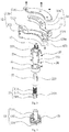
- the curved surface adjustment device 100 provided by the embodiment of the present invention includes an angle rotating assembly 1 and a locking assembly, wherein the angle rotating assembly 1 includes a middle plate 11 and a housing 12.
- the housing 12 includes a first mounting portion 121 and a receptacle 120, and an arc-shaped sliding groove 1231 is formed inside the receptacle 120.
- the middle plate 11 comprises a second mounting portion 111 and an arc-shaped sliding portion 112; the second mounting portion 111 is positioned outside the arc-shaped sliding groove 1231; the arc-shaped sliding portion 112 is positioned in arc-shaped sliding groove 1231; and the first mounting portion 121 and the second mounting portion 111 are positioned at two sides of the arc-shaped sliding groove 1231.
- the first mounting portion 121 is fixedly connected to the box frame 400, and the second mounting portion 111 is fixedly connected to the power control box 300.
- the locking assembly includes a locking mechanism 2 having a locking state and an unlocking state, when the locking mechanism 2 is in a locking state, the arc-shaped sliding portion 112 is locked in the arc-shaped sliding groove 1231, and when the locking mechanism is in an unlocking state, the arc-shaped sliding portion 112 can slide relative to the arc-shaped sliding groove 1231, so as to adjust the included angle between the first mounting portion 121 and the second mounting portion 111.
- the first mounting portion 121 is provided with a first mounting hole and the second mounting portion 111 is provided with a second mounting hole.
- the included angle between the first mounting portion 121 and the second mounting portion 111 refers to the included angle between the central axis of the first mounting hole and the central axis of the second mounting hole.
- the housing 12 comprises a first mounting portion 121 and a receptacle 120.
- the middle plate 11 includes a second mounting portion 111 and an arc-shaped sliding portion 112 positioned in the arc-shaped sliding groove 1231 of the receptacle 120.
- the first mounting portion 121 is fixedly connected to the box frame 400, and the second mounting portion 111 is fixedly connected to the power control box 300.
- the arc-shaped sliding portion 112 can slide relative to the arc-shaped sliding groove 1231 to adjust the included angle between the first mounting portion 121 and the second mounting portion 111, so as to adjust the curved surface radian of LED display screen, after the curved surface radian of LED display screen is adjusted, the locking mechanism 2 is switched to the locking state, then the arc-shaped sliding portion 112 will be locked in the arc-shaped sliding groove 1231, so that the curved surface radian of LED display screen will be fixed.
- the LED display screen adjusted by the curved surface adjustment device 100 of the embodiment of the present invention has better surface smoothness and smaller curved surface radius, and provides more excellent display effect. Moreover, the curved surface adjustment device 100 has the characteristics of reliable structure, high stability, more convenient adjustment, ect.
- the curved surface adjustment device 100 is installed between the box frame 400 and the power control box 300, assuming that the led display screen is planar in the initial state, and the included angle between the first mounting portion 121 and the second mounting portion 111 is the initial angle (the scale mark corresponding to the initial angle is 0).
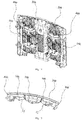
- the curved surface of the LED display screen is convex (as shown in Figs. 14 and 15 ).
- the angle between the first mounting portion 121 and the second mounting portion 111 is adjusted to a negative scale value
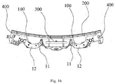
- the curved surface of the LED display screen is concave (as shown in Fig. 16 ).
- the LED display screen includes two curved surface adjustment devices 100 and two box frames 400, and the power control box 300 is located in the center of the LED module 200.
- the two box frames 400 are symmetrically and fixedly connected on both sides of the power control box 300, and the two curved surface adjustment devices 100 are symmetrically arranged on both sides of the power control box 300.
- the curved surface adjustment devices 100 are symmetrically arranged on the LED module 200, so that users can adjust the curved surface radians of both sides of the LED module 200 respectively by adjusting the curved surface adjustment devices 100 on both sides of the power control box 300.
- the force point is divided into two, which reduces the possibility of damage to the LED module 200 caused by excessive stress when adjusting the curved surface.
- the receptacle 120 includes a cover plate 122 and a bottom plate 123, and the arc-shaped sliding groove 1231 is disposed on the bottom plate 123.
- the cover plate 122 is fixedly connected to the bottom plate 123 and covers the arc-shaped sliding groove 1231, so that the arc-shaped sliding portion 112 is located in the arc-shaped sliding groove 1231, and preventing the arc-shaped sliding portion 112 from falling out of the arc-shaped sliding groove 1231.
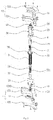
- the locking mechanism 2 includes a thread component 21, a top bar 22, a bushing 23 and a locking piece 13, and the bushing 23 is fixedly connected to the bottom plate 123.
- the bushing 23 is provided with a through hole 231 extending along the axial direction of the bushing 23, the bottom plate123 is provided with a locking hole 1232 axially penetrating the through hole 231, and the locking piece 13 is positioned in the locking hole 1232.
- the top bar 22 is slidably connected in the through hole 231, one end of the top bar 22 is provided with a threaded hole 221, the outer sidewall of the top bar 22 is provided with an anti-rotation slot 222, and the inner sidewall of the bushing 23 is provided with an anti-rotation screw 27, the anti-rotation slot 222 is in sliding contact with the anti-rotation screw 27, with the restriction of the anti-rotation screw 27, the top bar 22 can only slide along the through hole 231 of the bushing 23 and cannot rotate.
- One end of the thread component 21 is threadedly connected in the threaded hole 221, and the other end of the top bar 22 is abutted against the locking piece 13.
- Rotating the thread component 21 can slide the top bar 22 along the through hole 231, so that the locking piece 13 locks the arc-shaped sliding portion 112, making the arc-shaped sliding portion 112 locked in the arc-shaped sliding groove 1231, the included angle between the first mounting portion 121 and the second mounting portion 111 is relatively fixed.
- the locking piece 13 includes a locking plate 131 and a locking shaft 132 fixed on the locking plate 131, and the locking shaft 132 is provided with a positioning pin 133.
- the middle plate 11 is provided with a plurality of locking grooves 113 which can limit the positioning pin 133.
- the locking mechanism 2 further includes a spring 25 sleeved on the locking shaft 132 and supported between the locking plate 131 and the bottom plate 123.
- the spring 25 When the locking mechanism 2 is in a locking state, the spring 25 is compressed between the locking plate 131 and the bottom plate 123. When the locking mechanism 2 is switched to an unlocking state, the elastic force of the spring 25 can provide a restoring force for the locking piece 13.
- the thread component 21 includes a thread portion 211, a fixed portion 212, and a stop collar 213 located between the threaded portion 211 and the fixed portion 212.
- the thread portion 211 is threadedly connected in the thread hole 221 to realize a threaded connection between one end of the thread component 21 and the threaded hole 221.
- annular rotation slot 2131 is formed around the outer circumference of the stop collar 213.
- the locking mechanism 2 further includes a detent 26, the detent passes through the bushing 23 and snaps into the rotation slot 2131, so as to limit the thread component 21 to only rotatably connecting in the through hole 231 of the bushing 23.
- the locking assembly further comprises a rotating rod 3, one end of the rotating rod 3 is fixedly connected with the fixed portion 212, and the thread component 21 can be rotated in the through hole 231 of the bushing 23 by rotating the rotating rod 3.
- one end of the rotating rod 3 may be provided with a clamping hole 32 matching the shape of the fixed portion 212, and the fixed portion 212 is clamped in the clamping hole 32 to realize a fixed connection between one end of the rotating rod 3 and the fixed portion 212.
- the cross section of the fixed portion 212 is not circular.
- the locking assembly further comprises a rotation stop ring 4, the rotation stop ring 4 is sleeved on the bushing 23, the inner sidewall of the rotation stop ring 4 is provided with a rotation stop slot 41, and one end of the rotation stop ring 4 is provided with a rotation stop hole (not shown).
- the bushing 23 is provided with a first rotation stop block 232, the first rotation stop block 232 is slidably connected in the rotation stop slot 41, and one end of the rotating rod 3 is provided with a second rotation stop block 31 corresponding to the position of the rotation stop hole.
- the rotation stop ring 4 is provided with a rotation stop position and a rotatable position, and in the rotation stop position of the rotation stop ring 4, the second rotation stop block 31 is positioned in the rotation stop hole, to limit the relative rotation between the thread component 21 and the bushing 23. In the rotatable position of the rotation stop ring 4, the second rotation stop block 31 is away from the rotation stop hole, so that the thread component 21 can rotate relative to the bushing 23.
- the curved surface adjustment device 100 comprises two angle rotating assemblies 1, and the locking assembly comprises two locking mechanisms 2.
- the two angle rotating assemblies 1 are symmetrically arranged at both ends of the rotating rod 3, the two locking mechanisms 2 are symmetrically connected at both ends of the rotating rod 3 and are respectively positioned between the angle rotating assembly 1 and the rotating rod 3, and rotating the rotating rod 3 can make the two locking mechanisms 2 synchronously switch between locking state and unlocking state
- the two locking mechanisms 22 located at both ends of the rotating rod 3 are simultaneously switched from locking state to unlocking state, or simultaneously switched from unlocking state to locking state, so as to realize locking or unlocking of the arc-shaped sliding portion 112 of the two angle rotating assemblies 1 simultaneously.
- the first mounting portions 121 of the two angle rotating assemblies 1 are fixedly connected to the box frame 400 in parallel. And the second mounting portions 111 of the two angle rotating assemblies 1 are fixedly connected to the power control box 300 in parallel, so that the curved surface adjustment device 100 can simultaneously adjust both ends of the LED module 200, making the curved surface of the LED display screen more smoother.
- the arc-shaped sliding portion 112 of the middle plate 11 is provided with an angle identification 114 and a marble slot 115
- the bottom plate 123 is provided with an identification hole 1233 corresponding to the angle identification 114.
- the bottom plate 123 is provided with a marble screw 1235 at the position corresponding to the marble slot 115.
- the middle of a plurality of marble slots 115 is selected as the position of the marble screw 1235, which is the initial angle, with a scale of 0.
- the angle identification 114 can conveniently and intuitively adjust the angle and limit.
- the angle between the two adjacent compartments of the angle identification 114 is the same as the angle between the two adjacent locking grooves 113.
- the included angle between two adjacent locking grooves 113 is 2.5°.
- the angle between two adjacent compartments of the angle identification 114 is also 2.5°.
- angle identification 114 has 13 gears: -15°, -12.5°, -10°, -7.5°, -5°, -2.5°, 0°, 2.5°, 5°, 7.5°, 10°, 12.5°, 15°.
- the angle between the middle plate 11 and the housing 12 can be adjusted to 2.5°, that is, the curved surface adjustment angle of the LED display screen is 2.5°.
- the angle identification 114 the operator can be clearly informed of the adjustment angle of the LED display screen.
- the included angle between two adjacent locking grooves 113 can be customized according to user requirements.
- the marble slot 115 is located on the middle plate 11 provided with one side of the locking groove 113, and the marble screw 1235 is located in the marble slot 115.
- the marble screw 1235 is made of an extrudable elastic structure to improve hand feelings and reach a preliminary adjustment angle, and then locked by the locking mechanism 2.
- the middle plate 11 is provided with a guide arc hole 116
- the bottom plate 123 is provided with a guide post 1234
- the radians of the guide arc hole 116 and the arc-shaped sliding groove 1231 are the same and the centers of the circles coincide
- the guide post 1234 is positioned in the guide arc hole 116.
- the guide post 1234 cooperates with the guide arc hole 116 to provide guidance for the sliding motion of the arc-shaped sliding portion 112 of the middle plate 11 in the arc-shaped sliding groove 1231 of the bottom plate 123.
Landscapes
- Engineering & Computer Science (AREA)
- Theoretical Computer Science (AREA)
- Physics & Mathematics (AREA)
- General Physics & Mathematics (AREA)
- General Engineering & Computer Science (AREA)
- Computer Hardware Design (AREA)
- Power Engineering (AREA)
- Human Computer Interaction (AREA)
- Mechanical Engineering (AREA)
- Devices For Indicating Variable Information By Combining Individual Elements (AREA)
- Illuminated Signs And Luminous Advertising (AREA)
Applications Claiming Priority (2)
| Application Number | Priority Date | Filing Date | Title |
|---|---|---|---|
| CN201810955925.XA CN108962048B (zh) | 2018-08-21 | 2018-08-21 | 曲面调节装置及led显示屏 |
| PCT/CN2018/114796 WO2020037844A1 (fr) | 2018-08-21 | 2018-11-09 | Dispositif de réglage de surface incurvée et écran d'affichage à del |
Publications (3)
| Publication Number | Publication Date |
|---|---|
| EP3843068A1 true EP3843068A1 (fr) | 2021-06-30 |
| EP3843068A4 EP3843068A4 (fr) | 2022-05-18 |
| EP3843068B1 EP3843068B1 (fr) | 2025-07-09 |
Family
ID=64473365
Family Applications (1)
| Application Number | Title | Priority Date | Filing Date |
|---|---|---|---|
| EP18897864.7A Active EP3843068B1 (fr) | 2018-08-21 | 2018-11-09 | Dispositif de réglage de surface incurvée et écran d'affichage à del |
Country Status (4)
| Country | Link |
|---|---|
| US (1) | US11269384B2 (fr) |
| EP (1) | EP3843068B1 (fr) |
| CN (1) | CN108962048B (fr) |
| WO (1) | WO2020037844A1 (fr) |
Families Citing this family (21)
| Publication number | Priority date | Publication date | Assignee | Title |
|---|---|---|---|---|
| WO2020154338A1 (fr) * | 2019-01-25 | 2020-07-30 | Corning Incorporated | Système de molette à double élévation pour formation de verre fondu par étirage par le bas |
| CN110345352B (zh) * | 2019-08-01 | 2021-05-14 | 广东嘀嗒酷显柔性显示科技有限公司 | 一种具有多方位调节机构的led曲面显示屏 |
| CN111255999B (zh) | 2020-01-17 | 2022-01-28 | 深圳市洲明科技股份有限公司 | 一种弧形调节锁 |
| CN111402749B (zh) * | 2020-04-30 | 2024-10-29 | 深圳市雷迪奥视觉技术有限公司 | 定弧结构及显示屏 |
| CN111997992B (zh) * | 2020-09-23 | 2024-08-06 | 深圳市光祥科技股份有限公司 | 锁紧装置 |
| CN112185277B (zh) * | 2020-10-23 | 2024-08-09 | 深圳市联建光电有限公司 | 一种led显示屏快速拼装连接机构 |
| CN112443566B (zh) * | 2020-12-09 | 2025-03-18 | 深圳市光祥科技股份有限公司 | 弧形调节机构、led单元显示屏和led显示屏 |
| CN113819356B (zh) * | 2021-09-17 | 2025-02-14 | 深圳市光祥科技股份有限公司 | 一种弧形锁及拼接屏 |
| CN113915469B (zh) * | 2021-09-18 | 2023-03-03 | 深圳市建达强科技有限公司 | 一种户外智能广告机安全调试装置的调试方法 |
| CN114165688B (zh) * | 2021-11-29 | 2023-11-21 | 湖北联城通科技股份有限公司 | 一种主动式人脸识别感应门禁装置 |
| CN114776990B (zh) * | 2022-04-14 | 2025-01-28 | 广东技术师范大学 | 便于调整角度的图像处理装置 |
| CN115614353A (zh) * | 2022-09-26 | 2023-01-17 | 浙江大彩光电技术有限公司 | 一种显示屏箱体连接锁扣 |
| CN115620635A (zh) * | 2022-10-11 | 2023-01-17 | 佛山鼎辉光电科技有限公司 | 一种可弯曲led模组及led显示屏 |
| CN115624299A (zh) * | 2022-10-11 | 2023-01-20 | 力奇有限公司 | 手柄调节装置和洗地机 |
| CN116229840A (zh) * | 2023-03-09 | 2023-06-06 | 深圳市联诚发科技股份有限公司 | 用于led显示屏曲面调节的弧形锁装置 |
| CN220020503U (zh) * | 2023-03-22 | 2023-11-14 | 深圳市雷迪奥视觉技术有限公司 | 一种弧度调节机构及显示屏 |
| CN116386466A (zh) * | 2023-04-11 | 2023-07-04 | 深圳市联诚发科技股份有限公司 | 内曲面led智能显示器和内曲面led智能显示器显示控制方法 |
| CN116704896B (zh) * | 2023-06-09 | 2025-09-23 | 深圳市联诚发科技股份有限公司 | 曲面显示器曲率智能调节装置和智能显示控制方法 |
| CN116940006A (zh) * | 2023-08-22 | 2023-10-24 | 东莞鑫玖机电科技有限公司 | 一种可改变弧度的压铸箱体 |
| CN117249355B (zh) * | 2023-11-20 | 2024-02-09 | 中国地质大学(武汉) | 一种基于视觉的无线电测向装置 |
| CN121676839B (zh) * | 2026-02-09 | 2026-04-17 | 深圳市标杆节能科技有限公司 | 可调弯显示屏 |
Family Cites Families (10)
| Publication number | Priority date | Publication date | Assignee | Title |
|---|---|---|---|---|
| JP2006106046A (ja) * | 2004-09-30 | 2006-04-20 | Toshiba Transport Eng Inc | 接続具及び映像表示装置 |
| EP1837583A3 (fr) * | 2006-03-22 | 2009-08-05 | Samsung Electronics Co., Ltd. | Dispositif de support d'une unité de visualisation |
| CN203338684U (zh) * | 2013-06-06 | 2013-12-11 | 湖南易事达光电科技有限公司 | 可以任意调节角度的led显示屏 |
| US9834421B2 (en) * | 2013-11-15 | 2017-12-05 | Ronald E. Raper, Jr. | System, apparatus, and method for the transport and positioning of a display |
| US9377153B2 (en) * | 2014-09-12 | 2016-06-28 | Shenzhen China Star Optoelectronics Technology Co., Ltd | Multi-use display screen support device |
| CN204533998U (zh) * | 2015-01-04 | 2015-08-05 | 深圳市奥拓电子股份有限公司 | 角度调节装置及具有该装置的显示屏框架 |
| CN204596354U (zh) * | 2015-04-08 | 2015-08-26 | 深圳市创显光电有限公司 | 曲面调节装置及led显示屏 |
| CN207517295U (zh) * | 2017-09-11 | 2018-06-19 | 东莞市星光恒辉光电科技有限公司 | 一种可平面或曲面组装的led显示屏单元 |
| CN207381024U (zh) * | 2017-09-11 | 2018-05-18 | 东莞市星光恒辉光电科技有限公司 | 一种用于曲面led显示屏拼接的弧形锁 |
| CN209070890U (zh) * | 2018-08-21 | 2019-07-05 | 深圳市光祥科技股份有限公司 | 曲面调节装置及led显示屏 |
-
2018
- 2018-08-21 CN CN201810955925.XA patent/CN108962048B/zh active Active
- 2018-11-09 WO PCT/CN2018/114796 patent/WO2020037844A1/fr not_active Ceased
- 2018-11-09 EP EP18897864.7A patent/EP3843068B1/fr active Active
- 2018-11-09 US US16/476,547 patent/US11269384B2/en active Active
Also Published As
| Publication number | Publication date |
|---|---|
| CN108962048A (zh) | 2018-12-07 |
| WO2020037844A1 (fr) | 2020-02-27 |
| CN108962048B (zh) | 2023-12-01 |
| EP3843068B1 (fr) | 2025-07-09 |
| US11269384B2 (en) | 2022-03-08 |
| EP3843068A4 (fr) | 2022-05-18 |
| US20210263568A1 (en) | 2021-08-26 |
Similar Documents
| Publication | Publication Date | Title |
|---|---|---|
| US11269384B2 (en) | Curved surface adjustment device and LED display screen | |
| US8784164B2 (en) | Power tool with a shield | |
| US8418973B2 (en) | Multi-axis photographic tripod heads | |
| US11713844B2 (en) | Support device | |
| US7011371B1 (en) | Armrest assembly having a height adjustable function | |
| US11131422B2 (en) | Multifunctional stand frame for tablet electronic device | |
| EP3770366B1 (fr) | Base de réglage pour ferme-porte | |
| CA2695647A1 (fr) | Mecanisme de loquet avec dispositif de reglage de la distance | |
| US12501564B2 (en) | Electronic device and handle thereof | |
| CN209070890U (zh) | 曲面调节装置及led显示屏 | |
| CN112316411B (zh) | 电子设备及其手柄 | |
| KR102945437B1 (ko) | 로봇 | |
| US10139589B2 (en) | Zoom lens unit and indicator member | |
| CN222278174U (zh) | 一种拍摄手柄及拍摄辅助套件 | |
| US11994735B2 (en) | Camera lens assembly having linear guide | |
| CN101441394A (zh) | 投影仪调整装置 | |
| CN109736647B (zh) | 锁止机构及锁具 | |
| CN111367133A (zh) | 环形闪光灯组件及其支架 | |
| CN210959185U (zh) | 一种软件服务器自带的拆卸式壳体 | |
| CN210866493U (zh) | 极化馈源装置及卫星天线设备 | |
| CN217273187U (zh) | 一种快锁安装装置 | |
| CN219889199U (zh) | 一种可调节中轴角度的支架 | |
| CN223483927U (zh) | 夹桌式支撑装置 | |
| US10260714B2 (en) | Lamp casing mechanism | |
| CN209977675U (zh) | 手柄组件及手持拍摄装置 |
Legal Events
| Date | Code | Title | Description |
|---|---|---|---|
| STAA | Information on the status of an ep patent application or granted ep patent |
Free format text: STATUS: UNKNOWN |
|
| STAA | Information on the status of an ep patent application or granted ep patent |
Free format text: STATUS: THE INTERNATIONAL PUBLICATION HAS BEEN MADE |
|
| PUAI | Public reference made under article 153(3) epc to a published international application that has entered the european phase |
Free format text: ORIGINAL CODE: 0009012 |
|
| STAA | Information on the status of an ep patent application or granted ep patent |
Free format text: STATUS: REQUEST FOR EXAMINATION WAS MADE |
|
| 17P | Request for examination filed |
Effective date: 20190807 |
|
| AK | Designated contracting states |
Kind code of ref document: A1 Designated state(s): AL AT BE BG CH CY CZ DE DK EE ES FI FR GB GR HR HU IE IS IT LI LT LU LV MC MK MT NL NO PL PT RO RS SE SI SK SM TR |
|
| DAV | Request for validation of the european patent (deleted) | ||
| DAX | Request for extension of the european patent (deleted) | ||
| A4 | Supplementary search report drawn up and despatched |
Effective date: 20220421 |
|
| RIC1 | Information provided on ipc code assigned before grant |
Ipc: G09F 9/33 20060101AFI20220413BHEP |
|
| STAA | Information on the status of an ep patent application or granted ep patent |
Free format text: STATUS: EXAMINATION IS IN PROGRESS |
|
| 17Q | First examination report despatched |
Effective date: 20240221 |
|
| GRAP | Despatch of communication of intention to grant a patent |
Free format text: ORIGINAL CODE: EPIDOSNIGR1 |
|
| STAA | Information on the status of an ep patent application or granted ep patent |
Free format text: STATUS: GRANT OF PATENT IS INTENDED |
|
| INTG | Intention to grant announced |
Effective date: 20250410 |
|
| GRAS | Grant fee paid |
Free format text: ORIGINAL CODE: EPIDOSNIGR3 |
|
| GRAA | (expected) grant |
Free format text: ORIGINAL CODE: 0009210 |
|
| STAA | Information on the status of an ep patent application or granted ep patent |
Free format text: STATUS: THE PATENT HAS BEEN GRANTED |
|
| AK | Designated contracting states |
Kind code of ref document: B1 Designated state(s): AL AT BE BG CH CY CZ DE DK EE ES FI FR GB GR HR HU IE IS IT LI LT LU LV MC MK MT NL NO PL PT RO RS SE SI SK SM TR |
|
| REG | Reference to a national code |
Ref country code: GB Ref legal event code: FG4D |
|
| REG | Reference to a national code |
Ref country code: CH Ref legal event code: EP |
|
| REG | Reference to a national code |
Ref country code: IE Ref legal event code: FG4D |
|
| REG | Reference to a national code |
Ref country code: DE Ref legal event code: R096 Ref document number: 602018083510 Country of ref document: DE |
|
| REG | Reference to a national code |
Ref country code: NL Ref legal event code: MP Effective date: 20250709 |
|
| PG25 | Lapsed in a contracting state [announced via postgrant information from national office to epo] |
Ref country code: PT Free format text: LAPSE BECAUSE OF FAILURE TO SUBMIT A TRANSLATION OF THE DESCRIPTION OR TO PAY THE FEE WITHIN THE PRESCRIBED TIME-LIMIT Effective date: 20251110 |
|
| PG25 | Lapsed in a contracting state [announced via postgrant information from national office to epo] |
Ref country code: NL Free format text: LAPSE BECAUSE OF FAILURE TO SUBMIT A TRANSLATION OF THE DESCRIPTION OR TO PAY THE FEE WITHIN THE PRESCRIBED TIME-LIMIT Effective date: 20250709 |
|
| REG | Reference to a national code |
Ref country code: AT Ref legal event code: MK05 Ref document number: 1812632 Country of ref document: AT Kind code of ref document: T Effective date: 20250709 |
|
| PG25 | Lapsed in a contracting state [announced via postgrant information from national office to epo] |
Ref country code: IS Free format text: LAPSE BECAUSE OF FAILURE TO SUBMIT A TRANSLATION OF THE DESCRIPTION OR TO PAY THE FEE WITHIN THE PRESCRIBED TIME-LIMIT Effective date: 20251109 |
|
| PGFP | Annual fee paid to national office [announced via postgrant information from national office to epo] |
Ref country code: DE Payment date: 20251117 Year of fee payment: 8 |
|
| PGFP | Annual fee paid to national office [announced via postgrant information from national office to epo] |
Ref country code: GB Payment date: 20251126 Year of fee payment: 8 |
|
| PG25 | Lapsed in a contracting state [announced via postgrant information from national office to epo] |
Ref country code: NO Free format text: LAPSE BECAUSE OF FAILURE TO SUBMIT A TRANSLATION OF THE DESCRIPTION OR TO PAY THE FEE WITHIN THE PRESCRIBED TIME-LIMIT Effective date: 20251009 |
|
| REG | Reference to a national code |
Ref country code: LT Ref legal event code: MG9D |
|
| PG25 | Lapsed in a contracting state [announced via postgrant information from national office to epo] |
Ref country code: AT Free format text: LAPSE BECAUSE OF FAILURE TO SUBMIT A TRANSLATION OF THE DESCRIPTION OR TO PAY THE FEE WITHIN THE PRESCRIBED TIME-LIMIT Effective date: 20250709 |
|
| PG25 | Lapsed in a contracting state [announced via postgrant information from national office to epo] |
Ref country code: FI Free format text: LAPSE BECAUSE OF FAILURE TO SUBMIT A TRANSLATION OF THE DESCRIPTION OR TO PAY THE FEE WITHIN THE PRESCRIBED TIME-LIMIT Effective date: 20250709 |
|
| PG25 | Lapsed in a contracting state [announced via postgrant information from national office to epo] |
Ref country code: HR Free format text: LAPSE BECAUSE OF FAILURE TO SUBMIT A TRANSLATION OF THE DESCRIPTION OR TO PAY THE FEE WITHIN THE PRESCRIBED TIME-LIMIT Effective date: 20250709 |
|
| PGFP | Annual fee paid to national office [announced via postgrant information from national office to epo] |
Ref country code: FR Payment date: 20251127 Year of fee payment: 8 |
|
| PG25 | Lapsed in a contracting state [announced via postgrant information from national office to epo] |
Ref country code: GR Free format text: LAPSE BECAUSE OF FAILURE TO SUBMIT A TRANSLATION OF THE DESCRIPTION OR TO PAY THE FEE WITHIN THE PRESCRIBED TIME-LIMIT Effective date: 20251010 |
|
| PG25 | Lapsed in a contracting state [announced via postgrant information from national office to epo] |
Ref country code: SE Free format text: LAPSE BECAUSE OF FAILURE TO SUBMIT A TRANSLATION OF THE DESCRIPTION OR TO PAY THE FEE WITHIN THE PRESCRIBED TIME-LIMIT Effective date: 20250709 |
|
| PG25 | Lapsed in a contracting state [announced via postgrant information from national office to epo] |
Ref country code: LV Free format text: LAPSE BECAUSE OF FAILURE TO SUBMIT A TRANSLATION OF THE DESCRIPTION OR TO PAY THE FEE WITHIN THE PRESCRIBED TIME-LIMIT Effective date: 20250709 |
|
| PG25 | Lapsed in a contracting state [announced via postgrant information from national office to epo] |
Ref country code: PL Free format text: LAPSE BECAUSE OF FAILURE TO SUBMIT A TRANSLATION OF THE DESCRIPTION OR TO PAY THE FEE WITHIN THE PRESCRIBED TIME-LIMIT Effective date: 20250709 Ref country code: BG Free format text: LAPSE BECAUSE OF FAILURE TO SUBMIT A TRANSLATION OF THE DESCRIPTION OR TO PAY THE FEE WITHIN THE PRESCRIBED TIME-LIMIT Effective date: 20250709 |
|
| PG25 | Lapsed in a contracting state [announced via postgrant information from national office to epo] |
Ref country code: RS Free format text: LAPSE BECAUSE OF FAILURE TO SUBMIT A TRANSLATION OF THE DESCRIPTION OR TO PAY THE FEE WITHIN THE PRESCRIBED TIME-LIMIT Effective date: 20251009 |
|
| PG25 | Lapsed in a contracting state [announced via postgrant information from national office to epo] |
Ref country code: ES Free format text: LAPSE BECAUSE OF FAILURE TO SUBMIT A TRANSLATION OF THE DESCRIPTION OR TO PAY THE FEE WITHIN THE PRESCRIBED TIME-LIMIT Effective date: 20250709 |