EP3843178B1 - Battery module with improved safety, battery pack including the battery module and vehicle including the battery pack - Google Patents
Battery module with improved safety, battery pack including the battery module and vehicle including the battery pack Download PDFInfo
- Publication number
- EP3843178B1 EP3843178B1 EP19892391.4A EP19892391A EP3843178B1 EP 3843178 B1 EP3843178 B1 EP 3843178B1 EP 19892391 A EP19892391 A EP 19892391A EP 3843178 B1 EP3843178 B1 EP 3843178B1
- Authority
- EP
- European Patent Office
- Prior art keywords
- battery
- battery module
- battery cell
- bus bar
- block
- Prior art date
- Legal status (The legal status is an assumption and is not a legal conclusion. Google has not performed a legal analysis and makes no representation as to the accuracy of the status listed.)
- Active
Links
Images



Classifications
-
- H—ELECTRICITY
- H01—ELECTRIC ELEMENTS
- H01M—PROCESSES OR MEANS, e.g. BATTERIES, FOR THE DIRECT CONVERSION OF CHEMICAL ENERGY INTO ELECTRICAL ENERGY
- H01M50/00—Constructional details or processes of manufacture of the non-active parts of electrochemical cells other than fuel cells, e.g. hybrid cells
- H01M50/10—Primary casings; Jackets or wrappings
- H01M50/102—Primary casings; Jackets or wrappings characterised by their shape or physical structure
- H01M50/105—Pouches or flexible bags
-
- H—ELECTRICITY
- H01—ELECTRIC ELEMENTS
- H01M—PROCESSES OR MEANS, e.g. BATTERIES, FOR THE DIRECT CONVERSION OF CHEMICAL ENERGY INTO ELECTRICAL ENERGY
- H01M50/00—Constructional details or processes of manufacture of the non-active parts of electrochemical cells other than fuel cells, e.g. hybrid cells
- H01M50/10—Primary casings; Jackets or wrappings
- H01M50/116—Primary casings; Jackets or wrappings characterised by the material
-
- H—ELECTRICITY
- H01—ELECTRIC ELEMENTS
- H01M—PROCESSES OR MEANS, e.g. BATTERIES, FOR THE DIRECT CONVERSION OF CHEMICAL ENERGY INTO ELECTRICAL ENERGY
- H01M50/00—Constructional details or processes of manufacture of the non-active parts of electrochemical cells other than fuel cells, e.g. hybrid cells
- H01M50/10—Primary casings; Jackets or wrappings
- H01M50/172—Arrangements of electric connectors penetrating the casing
- H01M50/174—Arrangements of electric connectors penetrating the casing adapted for the shape of the cells
- H01M50/178—Arrangements of electric connectors penetrating the casing adapted for the shape of the cells for pouch or flexible bag cells
-
- H—ELECTRICITY
- H01—ELECTRIC ELEMENTS
- H01M—PROCESSES OR MEANS, e.g. BATTERIES, FOR THE DIRECT CONVERSION OF CHEMICAL ENERGY INTO ELECTRICAL ENERGY
- H01M50/00—Constructional details or processes of manufacture of the non-active parts of electrochemical cells other than fuel cells, e.g. hybrid cells
- H01M50/20—Mountings; Secondary casings or frames; Racks, modules or packs; Suspension devices; Shock absorbers; Transport or carrying devices; Holders
- H01M50/204—Racks, modules or packs for multiple batteries or multiple cells
- H01M50/207—Racks, modules or packs for multiple batteries or multiple cells characterised by their shape
- H01M50/211—Racks, modules or packs for multiple batteries or multiple cells characterised by their shape adapted for pouch cells
-
- H—ELECTRICITY
- H01—ELECTRIC ELEMENTS
- H01M—PROCESSES OR MEANS, e.g. BATTERIES, FOR THE DIRECT CONVERSION OF CHEMICAL ENERGY INTO ELECTRICAL ENERGY
- H01M50/00—Constructional details or processes of manufacture of the non-active parts of electrochemical cells other than fuel cells, e.g. hybrid cells
- H01M50/20—Mountings; Secondary casings or frames; Racks, modules or packs; Suspension devices; Shock absorbers; Transport or carrying devices; Holders
- H01M50/244—Secondary casings; Racks; Suspension devices; Carrying devices; Holders characterised by their mounting method
-
- H—ELECTRICITY
- H01—ELECTRIC ELEMENTS
- H01M—PROCESSES OR MEANS, e.g. BATTERIES, FOR THE DIRECT CONVERSION OF CHEMICAL ENERGY INTO ELECTRICAL ENERGY
- H01M50/00—Constructional details or processes of manufacture of the non-active parts of electrochemical cells other than fuel cells, e.g. hybrid cells
- H01M50/20—Mountings; Secondary casings or frames; Racks, modules or packs; Suspension devices; Shock absorbers; Transport or carrying devices; Holders
- H01M50/249—Mountings; Secondary casings or frames; Racks, modules or packs; Suspension devices; Shock absorbers; Transport or carrying devices; Holders specially adapted for aircraft or vehicles, e.g. cars or trains
-
- H—ELECTRICITY
- H01—ELECTRIC ELEMENTS
- H01M—PROCESSES OR MEANS, e.g. BATTERIES, FOR THE DIRECT CONVERSION OF CHEMICAL ENERGY INTO ELECTRICAL ENERGY
- H01M50/00—Constructional details or processes of manufacture of the non-active parts of electrochemical cells other than fuel cells, e.g. hybrid cells
- H01M50/20—Mountings; Secondary casings or frames; Racks, modules or packs; Suspension devices; Shock absorbers; Transport or carrying devices; Holders
- H01M50/289—Mountings; Secondary casings or frames; Racks, modules or packs; Suspension devices; Shock absorbers; Transport or carrying devices; Holders characterised by spacing elements or positioning means within frames, racks or packs
-
- H—ELECTRICITY
- H01—ELECTRIC ELEMENTS
- H01M—PROCESSES OR MEANS, e.g. BATTERIES, FOR THE DIRECT CONVERSION OF CHEMICAL ENERGY INTO ELECTRICAL ENERGY
- H01M50/00—Constructional details or processes of manufacture of the non-active parts of electrochemical cells other than fuel cells, e.g. hybrid cells
- H01M50/50—Current conducting connections for cells or batteries
-
- H—ELECTRICITY
- H01—ELECTRIC ELEMENTS
- H01M—PROCESSES OR MEANS, e.g. BATTERIES, FOR THE DIRECT CONVERSION OF CHEMICAL ENERGY INTO ELECTRICAL ENERGY
- H01M50/00—Constructional details or processes of manufacture of the non-active parts of electrochemical cells other than fuel cells, e.g. hybrid cells
- H01M50/50—Current conducting connections for cells or batteries
- H01M50/502—Interconnectors for connecting terminals of adjacent batteries; Interconnectors for connecting cells outside a battery casing
- H01M50/503—Interconnectors for connecting terminals of adjacent batteries; Interconnectors for connecting cells outside a battery casing characterised by the shape of the interconnectors
-
- H—ELECTRICITY
- H01—ELECTRIC ELEMENTS
- H01M—PROCESSES OR MEANS, e.g. BATTERIES, FOR THE DIRECT CONVERSION OF CHEMICAL ENERGY INTO ELECTRICAL ENERGY
- H01M50/00—Constructional details or processes of manufacture of the non-active parts of electrochemical cells other than fuel cells, e.g. hybrid cells
- H01M50/50—Current conducting connections for cells or batteries
- H01M50/502—Interconnectors for connecting terminals of adjacent batteries; Interconnectors for connecting cells outside a battery casing
- H01M50/505—Interconnectors for connecting terminals of adjacent batteries; Interconnectors for connecting cells outside a battery casing comprising a single busbar
-
- H—ELECTRICITY
- H01—ELECTRIC ELEMENTS
- H01M—PROCESSES OR MEANS, e.g. BATTERIES, FOR THE DIRECT CONVERSION OF CHEMICAL ENERGY INTO ELECTRICAL ENERGY
- H01M50/00—Constructional details or processes of manufacture of the non-active parts of electrochemical cells other than fuel cells, e.g. hybrid cells
- H01M50/50—Current conducting connections for cells or batteries
- H01M50/502—Interconnectors for connecting terminals of adjacent batteries; Interconnectors for connecting cells outside a battery casing
- H01M50/509—Interconnectors for connecting terminals of adjacent batteries; Interconnectors for connecting cells outside a battery casing characterised by the type of connection, e.g. mixed connections
- H01M50/51—Connection only in series
-
- H—ELECTRICITY
- H01—ELECTRIC ELEMENTS
- H01M—PROCESSES OR MEANS, e.g. BATTERIES, FOR THE DIRECT CONVERSION OF CHEMICAL ENERGY INTO ELECTRICAL ENERGY
- H01M50/00—Constructional details or processes of manufacture of the non-active parts of electrochemical cells other than fuel cells, e.g. hybrid cells
- H01M50/50—Current conducting connections for cells or batteries
- H01M50/502—Interconnectors for connecting terminals of adjacent batteries; Interconnectors for connecting cells outside a battery casing
- H01M50/514—Methods for interconnecting adjacent batteries or cells
- H01M50/516—Methods for interconnecting adjacent batteries or cells by welding, soldering or brazing
-
- H—ELECTRICITY
- H01—ELECTRIC ELEMENTS
- H01M—PROCESSES OR MEANS, e.g. BATTERIES, FOR THE DIRECT CONVERSION OF CHEMICAL ENERGY INTO ELECTRICAL ENERGY
- H01M50/00—Constructional details or processes of manufacture of the non-active parts of electrochemical cells other than fuel cells, e.g. hybrid cells
- H01M50/50—Current conducting connections for cells or batteries
- H01M50/502—Interconnectors for connecting terminals of adjacent batteries; Interconnectors for connecting cells outside a battery casing
- H01M50/521—Interconnectors for connecting terminals of adjacent batteries; Interconnectors for connecting cells outside a battery casing characterised by the material
- H01M50/522—Inorganic material
-
- H—ELECTRICITY
- H01—ELECTRIC ELEMENTS
- H01M—PROCESSES OR MEANS, e.g. BATTERIES, FOR THE DIRECT CONVERSION OF CHEMICAL ENERGY INTO ELECTRICAL ENERGY
- H01M50/00—Constructional details or processes of manufacture of the non-active parts of electrochemical cells other than fuel cells, e.g. hybrid cells
- H01M50/50—Current conducting connections for cells or batteries
- H01M50/502—Interconnectors for connecting terminals of adjacent batteries; Interconnectors for connecting cells outside a battery casing
- H01M50/521—Interconnectors for connecting terminals of adjacent batteries; Interconnectors for connecting cells outside a battery casing characterised by the material
- H01M50/526—Interconnectors for connecting terminals of adjacent batteries; Interconnectors for connecting cells outside a battery casing characterised by the material having a layered structure
-
- H—ELECTRICITY
- H01—ELECTRIC ELEMENTS
- H01M—PROCESSES OR MEANS, e.g. BATTERIES, FOR THE DIRECT CONVERSION OF CHEMICAL ENERGY INTO ELECTRICAL ENERGY
- H01M50/00—Constructional details or processes of manufacture of the non-active parts of electrochemical cells other than fuel cells, e.g. hybrid cells
- H01M50/50—Current conducting connections for cells or batteries
- H01M50/528—Fixed electrical connections, i.e. not intended for disconnection
-
- H—ELECTRICITY
- H01—ELECTRIC ELEMENTS
- H01M—PROCESSES OR MEANS, e.g. BATTERIES, FOR THE DIRECT CONVERSION OF CHEMICAL ENERGY INTO ELECTRICAL ENERGY
- H01M50/00—Constructional details or processes of manufacture of the non-active parts of electrochemical cells other than fuel cells, e.g. hybrid cells
- H01M50/50—Current conducting connections for cells or batteries
- H01M50/531—Electrode connections inside a battery casing
-
- H—ELECTRICITY
- H01—ELECTRIC ELEMENTS
- H01M—PROCESSES OR MEANS, e.g. BATTERIES, FOR THE DIRECT CONVERSION OF CHEMICAL ENERGY INTO ELECTRICAL ENERGY
- H01M50/00—Constructional details or processes of manufacture of the non-active parts of electrochemical cells other than fuel cells, e.g. hybrid cells
- H01M50/50—Current conducting connections for cells or batteries
- H01M50/543—Terminals
- H01M50/547—Terminals characterised by the disposition of the terminals on the cells
- H01M50/548—Terminals characterised by the disposition of the terminals on the cells on opposite sides of the cell
-
- H—ELECTRICITY
- H01—ELECTRIC ELEMENTS
- H01M—PROCESSES OR MEANS, e.g. BATTERIES, FOR THE DIRECT CONVERSION OF CHEMICAL ENERGY INTO ELECTRICAL ENERGY
- H01M50/00—Constructional details or processes of manufacture of the non-active parts of electrochemical cells other than fuel cells, e.g. hybrid cells
- H01M50/50—Current conducting connections for cells or batteries
- H01M50/543—Terminals
- H01M50/552—Terminals characterised by their shape
- H01M50/553—Terminals adapted for prismatic, pouch or rectangular cells
- H01M50/557—Plate-shaped terminals
-
- H—ELECTRICITY
- H01—ELECTRIC ELEMENTS
- H01M—PROCESSES OR MEANS, e.g. BATTERIES, FOR THE DIRECT CONVERSION OF CHEMICAL ENERGY INTO ELECTRICAL ENERGY
- H01M50/00—Constructional details or processes of manufacture of the non-active parts of electrochemical cells other than fuel cells, e.g. hybrid cells
- H01M50/50—Current conducting connections for cells or batteries
- H01M50/572—Means for preventing undesired use or discharge
- H01M50/574—Devices or arrangements for the interruption of current
-
- H—ELECTRICITY
- H01—ELECTRIC ELEMENTS
- H01M—PROCESSES OR MEANS, e.g. BATTERIES, FOR THE DIRECT CONVERSION OF CHEMICAL ENERGY INTO ELECTRICAL ENERGY
- H01M50/00—Constructional details or processes of manufacture of the non-active parts of electrochemical cells other than fuel cells, e.g. hybrid cells
- H01M50/50—Current conducting connections for cells or batteries
- H01M50/572—Means for preventing undesired use or discharge
- H01M50/574—Devices or arrangements for the interruption of current
- H01M50/581—Devices or arrangements for the interruption of current in response to temperature
-
- H—ELECTRICITY
- H01—ELECTRIC ELEMENTS
- H01M—PROCESSES OR MEANS, e.g. BATTERIES, FOR THE DIRECT CONVERSION OF CHEMICAL ENERGY INTO ELECTRICAL ENERGY
- H01M50/00—Constructional details or processes of manufacture of the non-active parts of electrochemical cells other than fuel cells, e.g. hybrid cells
- H01M50/50—Current conducting connections for cells or batteries
- H01M50/572—Means for preventing undesired use or discharge
- H01M50/574—Devices or arrangements for the interruption of current
- H01M50/583—Devices or arrangements for the interruption of current in response to current, e.g. fuses
-
- H—ELECTRICITY
- H01—ELECTRIC ELEMENTS
- H01M—PROCESSES OR MEANS, e.g. BATTERIES, FOR THE DIRECT CONVERSION OF CHEMICAL ENERGY INTO ELECTRICAL ENERGY
- H01M2200/00—Safety devices for primary or secondary batteries
-
- H—ELECTRICITY
- H01—ELECTRIC ELEMENTS
- H01M—PROCESSES OR MEANS, e.g. BATTERIES, FOR THE DIRECT CONVERSION OF CHEMICAL ENERGY INTO ELECTRICAL ENERGY
- H01M2200/00—Safety devices for primary or secondary batteries
- H01M2200/10—Temperature sensitive devices
-
- H—ELECTRICITY
- H01—ELECTRIC ELEMENTS
- H01M—PROCESSES OR MEANS, e.g. BATTERIES, FOR THE DIRECT CONVERSION OF CHEMICAL ENERGY INTO ELECTRICAL ENERGY
- H01M2220/00—Batteries for particular applications
- H01M2220/20—Batteries in motive systems, e.g. vehicle, ship, plane
-
- Y—GENERAL TAGGING OF NEW TECHNOLOGICAL DEVELOPMENTS; GENERAL TAGGING OF CROSS-SECTIONAL TECHNOLOGIES SPANNING OVER SEVERAL SECTIONS OF THE IPC; TECHNICAL SUBJECTS COVERED BY FORMER USPC CROSS-REFERENCE ART COLLECTIONS [XRACs] AND DIGESTS
- Y02—TECHNOLOGIES OR APPLICATIONS FOR MITIGATION OR ADAPTATION AGAINST CLIMATE CHANGE
- Y02E—REDUCTION OF GREENHOUSE GAS [GHG] EMISSIONS, RELATED TO ENERGY GENERATION, TRANSMISSION OR DISTRIBUTION
- Y02E60/00—Enabling technologies; Technologies with a potential or indirect contribution to GHG emissions mitigation
- Y02E60/10—Energy storage using batteries
Definitions
- the present disclosure relates to a battery module, and more particularly to a battery module that may block the current flow when the temperature rises.
- the present disclosure also relates to a battery pack including the battery module and a vehicle including the battery pack.
- the present application claims priority to Korean Patent Application No. 10-2018-0157556 filed on December 7, 2018 in the Republic of Korea.
- lithium secondary batteries are in the spotlight owing to the advantages of free charge and discharge, very low self discharge rate, and high energy density.
- secondary batteries are widely used not only in small devices such as portable electronic devices but also in medium and large devices such as vehicles and energy storage systems (ESSs).
- ESSs vehicles and energy storage systems
- a large number of secondary batteries are electrically connected to form a battery module or a battery pack in order to increase capacity and output power.
- pouch type secondary batteries are widely used in such medium large devices because of advantages such as easy lamination and light weight.
- Pouch type secondary batteries have a structure in which an electrode assembly to which an electrode lead is connected is accommodated in a pouch case with an electrolyte solution and sealed. A part of the electrode lead is exposed outside the pouch case, and the exposed electrode lead is electrically connected to a device to which secondary batteries are mounted or is used to electrically connect secondary batteries to each other.
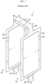
- FIG. 1 illustrates a part of a battery module manufactured by connecting pouch type battery cells. For example, a state in which two pouch type battery cells are connected in series is shown.
- pouch type battery cells 10 and 10' include two electrode leads 40 and 40' drawn out of a pouch case 30.
- the electrode leads 40 and 40' are divided into a positive electrode lead (+) and a negative electrode (-) lead according to an electrical polarity, and are electrically connected to an electrode assembly 20 sealed in the pouch case 30. That is, the positive electrode lead is electrically connected to a positive electrode plate of the electrode assembly 20, and the negative electrode lead is electrically connected to a negative electrode plate of the electrode assembly 20.
- PTC positive temperature coefficient
- Securing safety is very important in that explosion of a battery module or a battery pack not only may cause damage to electronic devices or vehicles, etc., to which it is employed, but also may lead to the safety threat of users and ignition. If the secondary battery is overheated, the risk of explosion and/or ignition increases, and sudden combustion or explosion due to overheating may cause injury to people and property. Therefore, there is a demand for introducing means for sufficiently securing safety in use of secondary batteries.
- the present disclosure is designed to solve the problems of the related art, and therefore the present disclosure is directed to providing a battery module with improved safety by blocking current when the temperature rises, a battery pack including the battery module, and a vehicle including the battery pack.
- a battery module as defined in the appended set of claims, the battery module including two or more battery cells, wherein the two or more battery cells are pouch type secondary batteries, each having a structure in which an electrode assembly having both ends respectively connected to one ends of electrode leads of opposite polarities is accommodated and sealed in a pouch case together with an electrolyte and other ends of the electrode leads are exposed to an outside of the pouch case, wherein the electrode leads and a bus bar are connected in electrically connecting a first battery cell and a second battery cell of the two or more battery cells, wherein the bus bar comprises a metal layer and a material layer that is normally conductive, but capable of acting as a resistor when a temperature rises, and wherein the material layer comprises a gas generating material that is decomposed at a certain temperature or higher to generate a gas and increase resistance.
- the two or more battery cells are pouch type secondary batteries, each having a structure in which an electrode assembly having both ends respectively connected to one ends of electrode leads of opposite polarities is accommodated and sealed in a pouch case
- the material layer includes the gas generating material, a conductive material and an adhesive.
- the conductive material may be connected and fixed to each other by the adhesive, and when the gas is generated, the conductive material may be disconnected to increase resistance.
- the bus bar includes a block and a body.
- the block is a portion connected to the electrode leads, the portion being separated from the body and embedded in the body and a surface of the block is exposed to an outside.
- the material layer is interposed between the body and the block.
- the bus bar may include a first block connected to an electrode lead of the first battery cell and a second block connected to an electrode lead of the second battery cell, and a current flow path from the first battery cell to the second battery cell may be provided in an order along the electrode lead of the first battery cell, the first block, a material layer interposed between the body and the first block, a material layer interposed between the body and the second block, the second block, and the electrode lead of the second battery cell.
- a battery pack including at least one battery module according to the present disclosure; and a pack case configured to package the at least one battery module.
- a vehicle including at least one battery pack according to the present disclosure.
- the battery module of the present disclosure implements means that automatically blocks the flow of current when the temperature rises by improving the bus bar, thereby securing the safety of the battery module doubly together with an overcharge protection function of the secondary battery protection circuit.
- a battery module may be provide using a bus bar capable of securing safety when connecting adjacent battery cells to form an electrical connection path.
- a bus bar capable of securing safety when connecting adjacent battery cells to form an electrical connection path.
- the present disclosure safety is ensured by improving the bus bar of the battery module. Except that the bus bar proposed in the present disclosure is used instead of the conventional bus bar, there is an advantage that the safety of the battery module may be secured without a relatively change to the process because the existing battery module manufacturing process may be used as it is. Since the battery cells themselves use the existing manufacturing process, a process change or an adjustment to a mass production process is not necessary.
- a secondary battery refers to a lithium secondary battery.
- the lithium secondary battery is collectively referred to as a secondary battery in which lithium ions act as operating ions during charging and discharging to cause an electrochemical reaction in a positive electrode plate and a negative electrode plate.
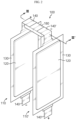
- FIG. 2 is a schematic view of a battery module according to an embodiment of the present disclosure.
- FIG. 3 is a cross-sectional view showing a coupling state between a bus bar and electrode leads in FIG. 2 .
- FIG. 4 is a top view of a bus bar included in a battery module according to an embodiment of the present disclosure.
- a battery module 100 includes battery cells 110 and 110' and a bus bar 180. Although a larger number of battery cells may be included in the battery module 100, some of them will be shown for convenience of illustration. For example, the state where the two pouch type battery cells 110 and 110' are connected in series is shown. However, this is merely exemplary and the present disclosure is not limited to this connection method.
- the battery cells 110 and 110' are secondary batteries and include two electrode leads 140 and 140' drawn out of a pouch case 130.
- the electrode leads 140 and 140' are divided into a positive electrode (+) lead and a negative electrode (-) lead according to electrical polarities, and are electrically connected to an electrode assembly 120 sealed in the pouch case 130. That is, the positive electrode lead is electrically connected to a positive electrode plate of the electrode assembly 120, and the negative electrode lead is electrically connected to a negative electrode plate of the electrode assembly 120.
- the battery cells 110 and 110' are pouch type secondary batteries having a structure in which the electrode assembly 120 having both ends respectively connected to one ends of the electrode leads 140 and 140' of opposite polarities is accommodated and sealed in the pouch case 130 together with an electrolyte and the other ends of the electrode leads 140 and 140' are exposed to the outside of the pouch case 130.
- one battery cell 110 is positioned on a left surface 181 of the bus bar 180, and the other battery cell 110' is positioned on a right surface 182.
- Each of the electrode leads 140 and 140' is connected to a block 184, and thus the electrode leads 140 and 140' are electrically connected to each other through the bus bar 180.
- the first battery cell 110 and the second battery cell 110' are connected in series through the bus bar 180.
- the bus bar 180 includes a first block 184a connected to the electrode lead 140 of the first battery cell 110 and a second block 184b connected to the electrode lead 140' of the second battery cell 110'.
- the current flow path from the first battery cell 110 to the second battery cell 110' is provided in an order along the electrode lead 140 of the first battery cell 110, the first block 184a, a material layer 185 interposed between a body 183 and the first block 184a, the body 183, the material layer 185 interposed between the body 183 and the second block 184b, the second block 184b and the electrode lead 140' of the second battery cell 110'.
- the bus bar 180 is in an approximately plate shape with a thin thickness compared to a length and a width.
- the particular difference between the bus bar 180 and the existing bus bar is a portion of the bus bar 180 which is connected to the electrode leads 140 and 140'. This portion is the block 184.
- the block 184 which is the portion separated from the body 183 of the bus bar 180 is embedded in the body 183 and has a surface exposed to the outside.
- the material layer 185 is interposed between the body 183 and the block 184.
- the body 183 and the block 184 are metal layers.
- the body 183 and the block 184 may be the same material.
- the material layer 185 is a material that is normally conductive but may act as a resistor when the temperature rises. As such, the material layer 185 is sandwiched between the body 183, which is the metal layer, and the block 184.
- the material layer 185 includes a gas generating material that is decomposed at a predetermined temperature or higher to generate gas and increase resistance.
- the material layer 185 includes the gas generating material, a conductive material and an adhesive.
- the conductive materials are connected and fixed to each other by the adhesive, and when the gas is generated in the gas generating material, the conductive materials may be disconnected to increase resistance.
- the gas generating material is preferably melamine cyanurate.
- Melamine cyanurate is a material used as a nitrogen-phosphorous flame retardant component in which nitrogen and phosphorus are combined, and may be obtained as a raw material having an average particle size of several tens of um through various manufacturers.
- Melamine cyanurate which is commonly used for a flame retardant application undergoes endothermic decomposition with the temperature exceeding about 300 °C. Melamine cyanurate is decomposed into melamine and cyanuric acid. Vaporized melamine emits inert nitrogen gas. The molecular weight of melamine cyanurate may be adjusted to control the decomposition temperature.
- the structural formula of melamine cyanurate is as follows.
- the conductive material is not particularly limited as long as it has conductivity, and may use, for example, graphite such as natural graphite and artificial graphite; carbon blacks such as carbon black, acetylene black, ketjen black, channel black, furnace black, lamp black, and summer black; conductive fibers such as carbon fibers and metal fibers; metal powders such as carbon fluoride powder, aluminum powder and nickel powder; conductive whiskers such as zinc oxide and potassium titanate; conductive metal oxides such as titanium oxide; conductive materials such as polyphenylene derivatives, and the like.
- graphite such as natural graphite and artificial graphite
- carbon blacks such as carbon black, acetylene black, ketjen black, channel black, furnace black, lamp black, and summer black
- conductive fibers such as carbon fibers and metal fibers
- metal powders such as carbon fluoride powder, aluminum powder and nickel powder
- conductive whiskers such as zinc oxide and potassium titanate
- conductive metal oxides such as titanium oxide
- the adhesive is a component that assists in the bonding of the gas generating material and the conductive material and the bonding of the body 183 and the block 184.
- the adhesive may include polyvinylidene fluoride, polyvinyl alcohol, carboxymethyl cellulose (CMC), starch, hydroxypropyl cellulose, regenerated cellulose, polyvinylpyrrolidone, tetrafluoroethylene, polyethylene, polypropylene, ethylenepropylene-diene terpolymer (EPDM), sulfonated EPDM, styrene butadiene rubber, fluorine rubber, various copolymers, and the like.
- the material layer 185 When the temperature rises to a certain temperature due to an abnormal circumstance, for example, when the temperature rises to 300 °C or higher, melamine cyanurate is decomposed and N 2 gas is generated in the material layer 185 inserted between the body 183 and the block 184. Accordingly, the material layer 185 increases in resistance to operate as a resistance layer.
- the material layer 185 may also serve to break electrical connections through volume expansion.
- the overall size of the bus bar 180 may be the same as that of the existing bus bar. Materials of the body 183 and the block 184 may be the same as those of the existing bus bar.
- the normal electrical conductivity of the material layer 185 may be similar to the electrical conductivity of the existing bus bar by making the conductive material in the material layer 185 equal to or higher than that of the existing bus bar.
- the conductivity of the material layer 185 in the bus bar 180 may be maintained, thereby expressing the performance of a battery module similar to that of the existing bus bar.
- the material layer 185 operates as a resistor to block the current, thereby improving the safety of a battery module including a battery cell manufactured to include the material layer 185.
- the bus bar 180 of which resistance increases when the temperature rises is configured between the battery cells 110 and 110' and thus the current flow through the bus bar 180 is blocked when the battery module 100 is overheated and reaches the temperature at which the gas generating material of the material layer 185 in the bus bar 180 is decomposed. Therefore, even when a secondary battery protection circuit does not operate, it is possible to block the flow of current such that no more current flows, for example, to prevent charging, thereby increasing the safety of the battery module 100.
- the battery module 100 of the present disclosure implements means that automatically blocks the flow of current when the temperature rises by improving the bus bar 180, thereby securing the safety of the battery module doubly together with an overcharge protection function of the secondary battery protection circuit.
- the block 184 is embedded in the body 183.
- the embedded block 184 is more difficult to be separated from the body 183 than in the simple layer stack structure and is structurally robust because there is no problem of being slipped and separated like a slip.
- the safety of the battery module 100 is secured through the improvement of the bus bar 180 of the battery module 100.
- the bus bar 180 according to the present disclosure is used to manufacture the battery module 100, and the existing battery cell manufacturing process is used as it is, and thus it is also advantageous that a change to the process or an adjustment to the mass production process is not necessary.
- the conductivity of the material layer 185 in the bus bar 180 is maintained under normal circumstances and the performance of the battery module similar to that of the existing battery module is expressed, and the safety of the battery module 100 may be improved by blocking the current flow when the temperature rises to a certain temperature or more due to an abnormal circumstance. Therefore, the safety of the battery module 100, the battery pack including the battery module, and the vehicle including the battery pack may be improved.
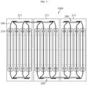
- FIG. 5 is a cross-sectional view schematically showing a battery module according to another embodiment of the present disclosure.
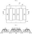
- FIG. 6 is a top view of a portion of a first bus bar included in the battery module of FIG. 5
- FIG. 7 is a cross-sectional view taken along line VII-VII' of FIG. 6
- FIG. 8 is a top view of a portion of a second bus bar included in the battery module of FIG. 5
- FIG. 9 is a cross-sectional taken along line IX-IX' of FIG. 8 .
- a battery module 1000 of FIG. 5 illustrates an example of a 4P3S connection. That is, three cell banks 211 in which four battery cells 210 are connected in parallel (P) are connected in series (S). Each of the battery cells 210 may be a pouch type battery cell as shown in FIG. 2 , etc., and the battery cells 210 may have the same structure as the battery cell 110.
- Electrode leads 240 protrude from both ends of the battery cell 210.
- the electrode leads 240 are stacked to have the same polarity in the cell banks 211 connected in parallel.
- the electrode leads 240 are stacked to have opposite polarities between the cell banks 211.
- the first bus bar 280 is for connecting the electrode leads 240 of the same polarity in one cell bank 211
- the second bus bar 290 is also for connecting the electrode leads 240 of different polarities between the two cell banks 211.
- the first bus bar 280 and the second bus bar 290 are respectively provided with grooves 286 and 296 through which the electrode leads 240 penetrate.
- the first bus bar 280 and the second bus bar 290 are similar to the bus bar 180 described in the previous embodiment. That is, the first bus bar 280 includes a body 283, a block 284, and a material layer 285, and the second bus bar 290 also includes a body 293, a block 294, and a material layer 295.
- the material layers 285 and 295 are the same as the material layers 185 described above, and are conductive in normal circumstances, but may act as resistors when the temperature rises, thereby blocking an electrical connection between the battery cells 210.
- the description provided in the previous embodiment may be used as it is.
- a short circuit current is the representative cause of deterioration of safety due to the rapid rise in temperature of a lithium secondary battery. It is very important to ensure the safety in the short circuit in the safety of a battery module in which multiple battery cells are connected or a battery pack. The lower the short circuit resistance, the higher the short circuit current flows to generate a great amount of heat, and if the battery cell becomes unbearable, ignition occurs. Some safety results are obtained when the short circuit resistance is very low, where heat generated by the flow of high current exceeds 660 °C and electrode leads melt, resulting in a break in a current flow to ensure the safety.
- the generated heat is lower than 660 °C, because the electrode leads do not melt, the flow of current continues, a high heat is accumulated, and the battery cells are unbearable, causing ignition to occur. Meanwhile, the high current may flow even under normal circumstances.
- a large current flows in the battery module during rapid charging, rapid acceleration, or starting, causing a high temperature to occur in the electrode leads. In such an abnormal circumstance, the electric vehicle must not operate. To prevent this, it is necessary to block the flow of current at a temperature of about 250 °C or higher.
- the battery module 1000 when the battery module 1000 reaches about 300 °C, gas is generated in the material layers 285 and 295 to increase the resistance of the material layers 285 and 295. Accordingly, the battery module 1000 does not operate in the normal high current range but operates only when an actual short circuit occurs and is overheated at a temperature equal to or higher than 300 °C, thereby ensuring safety against ignition, explosion, etc. There is also an advantage that an energy density is not reduced since it does not occupy a space in the module, such as a PTC device or a fuse which is a different safety enhancing device.
- the battery module is also suitable for use as a power source for a medium and large device requiring high temperature stability, long cycle characteristics, high rate characteristics, etc.
- Preferred examples of the medium and large device include a power tool that is driven by an electric motor; electric vehicles including EV, HEV, PHEV, and the like; electric motorcycles including e-bikes and e-scooters; electric golf carts; and ESS, but are not limited thereto.
- FIG. 10 is a diagram illustrating a battery pack according to an embodiment of the present disclosure.
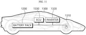
- FIG. 11 is a diagram illustrating a vehicle according to an embodiment of the present disclosure.
- a battery pack 1200 may include at least one battery module according to the foregoing embodiment, for example, the battery module 100 of the second embodiment and a pack case 1210 for packaging the battery pack 1200.
- the battery pack 1200 according to the present disclosure in addition to the battery module 100 and the pack case 1210, may further include various devices for controlling charging and discharging of the battery module 100, such as a battery management system (BMS), a current sensor, a fuse, etc.
- BMS battery management system
- the battery pack 1200 may be provided in a vehicle 1300 as a fuel source of the vehicle 1300.
- the battery pack 1200 may be provided in the vehicle 1300 in other ways that may utilize electric vehicles, hybrid vehicles, and the other battery pack 1200 as fuel sources.
- the vehicle 1300 may be an electric vehicle.
- the battery pack 1200 may be used as an electric energy source that drives the vehicle 1300 by providing a driving force to a motor 1310 of the electric vehicle.
- the battery pack 1200 has a high nominal voltage of 100V or higher.
- the battery pack 1200 is set to 270V.
- the battery pack 1200 may be charged or discharged by an inverter 1320 according to the driving of the motor 1310 and/or an internal combustion engine.
- the battery pack 1200 may be charged by a regenerative charging device coupled with a break.
- the battery pack 1200 may be electrically connected to the motor 1310 of the vehicle 1300 through the inverter 1320.
- the battery pack 1200 also includes the BMS.
- the BMS estimates the state of battery cells in the battery pack 1200 and manages the battery pack 1200 using estimated state information. For example, the BMS estimates and manages state information of the battery pack 1200 such as state of charge (SOC) of the battery pack 1200, state of health (SOH), maximum input/output power allowance, output voltage, etc.
- the BMS may use the state information to control the charging or discharging of the battery pack 1200, and further, estimate the replacement time of the battery pack 1200.
- An ECU 1330 is an electronic control device for controlling the state of the vehicle 1300.
- the ECU 1330 determines torque information based on information such as an accelerator, a brake, a speed, etc., and controls the output of the motor 1310 to match the torque information.
- the ECU 1330 transmits a control signal to the inverter 1320 such that the battery pack 1200 may be charged or discharged based on the state information such as SOC and SOH of the battery pack 1200 received by the BMS.
- the inverter 1320 causes the battery pack 1200 to be charged or discharged based on the control signal of the ECU 1330.
- the motor 1310 drives the vehicle 1300 based on control information (e.g., torque information) transmitted from the ECU 1330 using electric energy of the battery pack 1200.
- control information e.g., torque information
- the vehicle 1300 includes the battery pack 1200 according to the present disclosure.
- the battery pack 1200 includes the battery module 100 with improved safety as described above. Therefore, the stability of the battery pack 1200 is improved, the battery pack 1200 is excellent in stability and may be used for a long time, and thus the vehicle 1300 including the battery pack 1200 is safe and easy to operate.
- the battery pack 1200 may also be provided in other devices, equipment, and facilities, such as an ESS using a secondary battery, in addition to the vehicle 1300.
- the battery pack 1200 according to the present embodiment and devices or equipment and facilities including the battery pack 1200, such as the vehicle 1300, include the battery module 100 described above, and thus the battery pack 1200 having all the advantages owing to the battery module 100 described above and devices or equipment and facilities such as the vehicle 1300 including the battery pack 1200 may be implemented.
Landscapes
- Chemical & Material Sciences (AREA)
- Chemical Kinetics & Catalysis (AREA)
- Electrochemistry (AREA)
- General Chemical & Material Sciences (AREA)
- Engineering & Computer Science (AREA)
- Aviation & Aerospace Engineering (AREA)
- Inorganic Chemistry (AREA)
- Battery Mounting, Suspending (AREA)
- Connection Of Batteries Or Terminals (AREA)
Applications Claiming Priority (2)
| Application Number | Priority Date | Filing Date | Title |
|---|---|---|---|
| KR1020180157556A KR102450418B1 (ko) | 2018-12-07 | 2018-12-07 | 안전성이 개선된 배터리 모듈, 이러한 배터리 모듈을 포함하는 배터리 팩 및 이러한 배터리 팩을 포함하는 자동차 |
| PCT/KR2019/015085 WO2020116799A1 (ko) | 2018-12-07 | 2019-11-07 | 안전성이 개선된 배터리 모듈, 이러한 배터리 모듈을 포함하는 배터리 팩 및 이러한 배터리 팩을 포함하는 자동차 |
Publications (3)
| Publication Number | Publication Date |
|---|---|
| EP3843178A1 EP3843178A1 (en) | 2021-06-30 |
| EP3843178A4 EP3843178A4 (en) | 2021-11-03 |
| EP3843178B1 true EP3843178B1 (en) | 2025-01-01 |
Family
ID=70973519
Family Applications (1)
| Application Number | Title | Priority Date | Filing Date |
|---|---|---|---|
| EP19892391.4A Active EP3843178B1 (en) | 2018-12-07 | 2019-11-07 | Battery module with improved safety, battery pack including the battery module and vehicle including the battery pack |
Country Status (8)
| Country | Link |
|---|---|
| US (1) | US11658364B2 (ko) |
| EP (1) | EP3843178B1 (ko) |
| JP (1) | JP7150881B2 (ko) |
| KR (1) | KR102450418B1 (ko) |
| CN (1) | CN112106228B (ko) |
| ES (1) | ES3009550T3 (ko) |
| HU (1) | HUE070036T2 (ko) |
| WO (1) | WO2020116799A1 (ko) |
Families Citing this family (9)
| Publication number | Priority date | Publication date | Assignee | Title |
|---|---|---|---|---|
| KR102691428B1 (ko) * | 2018-12-13 | 2024-08-01 | 주식회사 엘지에너지솔루션 | 전지 모듈 |
| CN113661604A (zh) * | 2019-06-11 | 2021-11-16 | 株式会社Lg新能源 | 提高安全性的端子汇流排及包括其的电池模块和电池组 |
| US12334258B2 (en) | 2020-12-31 | 2025-06-17 | Hyundai Motor Company | Energy storage module |
| KR102598968B1 (ko) * | 2020-12-31 | 2023-11-07 | 현대자동차주식회사 | 에너지 저장 모듈 |
| US12087973B2 (en) | 2020-12-31 | 2024-09-10 | Hyundai Motor Company | Energy storage device |
| JP7380631B2 (ja) * | 2021-03-31 | 2023-11-15 | トヨタ自動車株式会社 | 組電池 |
| KR20220149249A (ko) * | 2021-04-30 | 2022-11-08 | 주식회사 엘지에너지솔루션 | 전지 팩 및 이를 포함하는 디바이스 |
| US11791515B2 (en) | 2021-08-18 | 2023-10-17 | Beta Air, Llc | Battery assembly for an aircraft |
| US20250372829A1 (en) * | 2024-05-31 | 2025-12-04 | Fluence Energy, Llc | Energy storage system including submodules having structural interconnect boards |
Family Cites Families (16)
| Publication number | Priority date | Publication date | Assignee | Title |
|---|---|---|---|---|
| JPH077023A (ja) | 1993-06-18 | 1995-01-10 | Toshiba Corp | 樹脂封止型半導体装置 |
| DE60030743T2 (de) * | 1999-07-12 | 2007-09-06 | Ibiden Co., Ltd., Ogaki | Verfahren zum Herstellen einer Leiterplatte |
| KR101310423B1 (ko) * | 2006-07-24 | 2013-09-24 | 주식회사 엘지화학 | 안전성 향상을 위한 전기화학소자용 센터핀 및 이를포함하는 전기화학소자 |
| DE102009013346A1 (de) * | 2009-03-16 | 2010-09-30 | Li-Tec Battery Gmbh | Elektroenergie-Speichervorrichtung mit Flachzellen und Abstandselementen |
| JP5570383B2 (ja) | 2010-10-15 | 2014-08-13 | 株式会社神戸製鋼所 | 導電性連結部材、導電性連結部材の製造方法、及び導電性連結部材が電極とされたバッテリ |
| KR20120070851A (ko) * | 2010-12-22 | 2012-07-02 | 주식회사 엘지화학 | 전도성 고분자를 포함하고 있는 전극 리드를 사용하는 이차전지 |
| KR101433199B1 (ko) * | 2011-11-28 | 2014-08-26 | 주식회사 엘지화학 | 배터리 모듈 및 배터리 모듈에 적용되는 버스 바 |
| KR101595607B1 (ko) * | 2011-12-07 | 2016-02-18 | 주식회사 엘지화학 | 안전성이 향상된 이차전지 |
| KR20140064093A (ko) * | 2012-11-19 | 2014-05-28 | 주식회사 엘지화학 | 안전성이 향상된 배터리 모듈 및 이에 적용되는 버스 바 |
| KR101428331B1 (ko) | 2012-12-27 | 2014-08-07 | 현대자동차주식회사 | 차량용 배터리모듈의 안전장치 |
| JP5705930B2 (ja) | 2013-08-21 | 2015-04-22 | 日本写真印刷株式会社 | 複合成形品及びその製造方法 |
| JP6696426B2 (ja) | 2014-08-19 | 2020-05-20 | 日本電気株式会社 | 電流遮断機能を有する電池およびその製造方法 |
| JP6376405B2 (ja) | 2015-05-28 | 2018-08-22 | 豊田合成株式会社 | 電池モジュール |
| EP3154107B1 (en) | 2015-10-06 | 2018-09-12 | Samsung SDI Co., Ltd. | Busbar |
| WO2018155281A1 (ja) * | 2017-02-24 | 2018-08-30 | 日本ゼオン株式会社 | 電気化学素子用電極および電気化学素子 |
| KR102201344B1 (ko) | 2017-05-26 | 2021-01-08 | 주식회사 엘지화학 | 배터리 모듈과 이를 포함하는 배터리 팩 및 자동차 |
-
2018
- 2018-12-07 KR KR1020180157556A patent/KR102450418B1/ko active Active
-
2019
- 2019-11-07 JP JP2020565814A patent/JP7150881B2/ja active Active
- 2019-11-07 EP EP19892391.4A patent/EP3843178B1/en active Active
- 2019-11-07 HU HUE19892391A patent/HUE070036T2/hu unknown
- 2019-11-07 CN CN201980030902.0A patent/CN112106228B/zh active Active
- 2019-11-07 US US17/049,914 patent/US11658364B2/en active Active
- 2019-11-07 WO PCT/KR2019/015085 patent/WO2020116799A1/ko not_active Ceased
- 2019-11-07 ES ES19892391T patent/ES3009550T3/es active Active
Also Published As
| Publication number | Publication date |
|---|---|
| EP3843178A4 (en) | 2021-11-03 |
| EP3843178A1 (en) | 2021-06-30 |
| US20210242548A1 (en) | 2021-08-05 |
| JP7150881B2 (ja) | 2022-10-11 |
| CN112106228A (zh) | 2020-12-18 |
| KR102450418B1 (ko) | 2022-09-30 |
| US11658364B2 (en) | 2023-05-23 |
| HUE070036T2 (hu) | 2025-05-28 |
| WO2020116799A1 (ko) | 2020-06-11 |
| KR20200069953A (ko) | 2020-06-17 |
| JP2021525441A (ja) | 2021-09-24 |
| ES3009550T3 (en) | 2025-03-27 |
| CN112106228B (zh) | 2022-11-25 |
Similar Documents
| Publication | Publication Date | Title |
|---|---|---|
| EP3843178B1 (en) | Battery module with improved safety, battery pack including the battery module and vehicle including the battery pack | |
| JP7206423B2 (ja) | 安全性改善用ターミナルバスバー、それを含むバッテリーモジュール及びバッテリーパック | |
| EP3512008B1 (en) | Battery module, and battery pack and vehicle including the same | |
| JP3729164B2 (ja) | 自動車用電池 | |
| EP3836294B1 (en) | Battery module with improved heat dissipation, battery pack including the battery module and vehicle including the battery pack | |
| EP2026403B1 (en) | Cell and battery incorporating the cell | |
| CN102035028A (zh) | 非水电解质电池、电池组以及汽车 | |
| US11342612B2 (en) | Battery module with improved heat dissipation, battery pack including the battery module and vehicle including the battery pack | |
| JP5866463B2 (ja) | 安全性が向上した電池セルアセンブリ及びそれを含む電池モジュール | |
| US11881597B2 (en) | Battery module with improved safety, battery pack comprising battery module, and vehicle comprising battery pack | |
| KR102903027B1 (ko) | 안전성이 개선된 배터리 모듈, 이러한 배터리 모듈을 포함하는 배터리 팩 및 이러한 배터리 팩을 포함하는 자동차 | |
| KR20180138028A (ko) | 배터리 모듈과 이를 포함하는 배터리 팩 및 자동차 |
Legal Events
| Date | Code | Title | Description |
|---|---|---|---|
| STAA | Information on the status of an ep patent application or granted ep patent |
Free format text: STATUS: THE INTERNATIONAL PUBLICATION HAS BEEN MADE |
|
| PUAI | Public reference made under article 153(3) epc to a published international application that has entered the european phase |
Free format text: ORIGINAL CODE: 0009012 |
|
| STAA | Information on the status of an ep patent application or granted ep patent |
Free format text: STATUS: REQUEST FOR EXAMINATION WAS MADE |
|
| 17P | Request for examination filed |
Effective date: 20210322 |
|
| AK | Designated contracting states |
Kind code of ref document: A1 Designated state(s): AL AT BE BG CH CY CZ DE DK EE ES FI FR GB GR HR HU IE IS IT LI LT LU LV MC MK MT NL NO PL PT RO RS SE SI SK SM TR |
|
| REG | Reference to a national code |
Ref country code: DE Ref legal event code: R079 Free format text: PREVIOUS MAIN CLASS: H01M0002340000 Ipc: H01M0050211000 Ref document number: 602019064443 Country of ref document: DE |
|
| A4 | Supplementary search report drawn up and despatched |
Effective date: 20210930 |
|
| RIC1 | Information provided on ipc code assigned before grant |
Ipc: H01M 50/583 20210101ALI20210924BHEP Ipc: H01M 50/557 20210101ALI20210924BHEP Ipc: H01M 50/548 20210101ALI20210924BHEP Ipc: H01M 50/528 20210101ALI20210924BHEP Ipc: H01M 50/516 20210101ALI20210924BHEP Ipc: H01M 50/505 20210101ALI20210924BHEP Ipc: H01M 50/289 20210101ALI20210924BHEP Ipc: H01M 50/249 20210101ALI20210924BHEP Ipc: H01M 50/581 20210101ALI20210924BHEP Ipc: H01M 50/211 20210101AFI20210924BHEP |
|
| RAP1 | Party data changed (applicant data changed or rights of an application transferred) |
Owner name: LG ENERGY SOLUTION LTD. |
|
| DAV | Request for validation of the european patent (deleted) | ||
| DAX | Request for extension of the european patent (deleted) | ||
| RAP3 | Party data changed (applicant data changed or rights of an application transferred) |
Owner name: LG ENERGY SOLUTION, LTD. |
|
| GRAP | Despatch of communication of intention to grant a patent |
Free format text: ORIGINAL CODE: EPIDOSNIGR1 |
|
| STAA | Information on the status of an ep patent application or granted ep patent |
Free format text: STATUS: GRANT OF PATENT IS INTENDED |
|
| GRAS | Grant fee paid |
Free format text: ORIGINAL CODE: EPIDOSNIGR3 |
|
| INTG | Intention to grant announced |
Effective date: 20241018 |
|
| GRAA | (expected) grant |
Free format text: ORIGINAL CODE: 0009210 |
|
| STAA | Information on the status of an ep patent application or granted ep patent |
Free format text: STATUS: THE PATENT HAS BEEN GRANTED |
|
| P01 | Opt-out of the competence of the unified patent court (upc) registered |
Free format text: CASE NUMBER: APP_59651/2024 Effective date: 20241104 |
|
| AK | Designated contracting states |
Kind code of ref document: B1 Designated state(s): AL AT BE BG CH CY CZ DE DK EE ES FI FR GB GR HR HU IE IS IT LI LT LU LV MC MK MT NL NO PL PT RO RS SE SI SK SM TR |
|
| REG | Reference to a national code |
Ref country code: GB Ref legal event code: FG4D |
|
| REG | Reference to a national code |
Ref country code: CH Ref legal event code: EP |
|
| REG | Reference to a national code |
Ref country code: DE Ref legal event code: R096 Ref document number: 602019064443 Country of ref document: DE |
|
| REG | Reference to a national code |
Ref country code: IE Ref legal event code: FG4D |
|
| REG | Reference to a national code |
Ref country code: ES Ref legal event code: FG2A Ref document number: 3009550 Country of ref document: ES Kind code of ref document: T3 Effective date: 20250327 |
|
| REG | Reference to a national code |
Ref country code: LT Ref legal event code: MG9D |
|
| REG | Reference to a national code |
Ref country code: NL Ref legal event code: MP Effective date: 20250101 |
|
| REG | Reference to a national code |
Ref country code: HU Ref legal event code: AG4A Ref document number: E070036 Country of ref document: HU |
|
| REG | Reference to a national code |
Ref country code: AT Ref legal event code: MK05 Ref document number: 1757262 Country of ref document: AT Kind code of ref document: T Effective date: 20250101 |
|
| PG25 | Lapsed in a contracting state [announced via postgrant information from national office to epo] |
Ref country code: NL Free format text: LAPSE BECAUSE OF FAILURE TO SUBMIT A TRANSLATION OF THE DESCRIPTION OR TO PAY THE FEE WITHIN THE PRESCRIBED TIME-LIMIT Effective date: 20250101 |
|
| PG25 | Lapsed in a contracting state [announced via postgrant information from national office to epo] |
Ref country code: FI Free format text: LAPSE BECAUSE OF FAILURE TO SUBMIT A TRANSLATION OF THE DESCRIPTION OR TO PAY THE FEE WITHIN THE PRESCRIBED TIME-LIMIT Effective date: 20250101 |
|
| PG25 | Lapsed in a contracting state [announced via postgrant information from national office to epo] |
Ref country code: PL Free format text: LAPSE BECAUSE OF FAILURE TO SUBMIT A TRANSLATION OF THE DESCRIPTION OR TO PAY THE FEE WITHIN THE PRESCRIBED TIME-LIMIT Effective date: 20250101 |
|
| PG25 | Lapsed in a contracting state [announced via postgrant information from national office to epo] |
Ref country code: NO Free format text: LAPSE BECAUSE OF FAILURE TO SUBMIT A TRANSLATION OF THE DESCRIPTION OR TO PAY THE FEE WITHIN THE PRESCRIBED TIME-LIMIT Effective date: 20250401 Ref country code: IS Free format text: LAPSE BECAUSE OF FAILURE TO SUBMIT A TRANSLATION OF THE DESCRIPTION OR TO PAY THE FEE WITHIN THE PRESCRIBED TIME-LIMIT Effective date: 20250501 |
|
| PG25 | Lapsed in a contracting state [announced via postgrant information from national office to epo] |
Ref country code: HR Free format text: LAPSE BECAUSE OF FAILURE TO SUBMIT A TRANSLATION OF THE DESCRIPTION OR TO PAY THE FEE WITHIN THE PRESCRIBED TIME-LIMIT Effective date: 20250101 |
|
| PG25 | Lapsed in a contracting state [announced via postgrant information from national office to epo] |
Ref country code: PT Free format text: LAPSE BECAUSE OF FAILURE TO SUBMIT A TRANSLATION OF THE DESCRIPTION OR TO PAY THE FEE WITHIN THE PRESCRIBED TIME-LIMIT Effective date: 20250502 Ref country code: LV Free format text: LAPSE BECAUSE OF FAILURE TO SUBMIT A TRANSLATION OF THE DESCRIPTION OR TO PAY THE FEE WITHIN THE PRESCRIBED TIME-LIMIT Effective date: 20250101 |
|
| PG25 | Lapsed in a contracting state [announced via postgrant information from national office to epo] |
Ref country code: GR Free format text: LAPSE BECAUSE OF FAILURE TO SUBMIT A TRANSLATION OF THE DESCRIPTION OR TO PAY THE FEE WITHIN THE PRESCRIBED TIME-LIMIT Effective date: 20250402 Ref country code: BG Free format text: LAPSE BECAUSE OF FAILURE TO SUBMIT A TRANSLATION OF THE DESCRIPTION OR TO PAY THE FEE WITHIN THE PRESCRIBED TIME-LIMIT Effective date: 20250101 |
|
| PG25 | Lapsed in a contracting state [announced via postgrant information from national office to epo] |
Ref country code: AT Free format text: LAPSE BECAUSE OF FAILURE TO SUBMIT A TRANSLATION OF THE DESCRIPTION OR TO PAY THE FEE WITHIN THE PRESCRIBED TIME-LIMIT Effective date: 20250101 |
|
| PG25 | Lapsed in a contracting state [announced via postgrant information from national office to epo] |
Ref country code: CZ Free format text: LAPSE BECAUSE OF FAILURE TO SUBMIT A TRANSLATION OF THE DESCRIPTION OR TO PAY THE FEE WITHIN THE PRESCRIBED TIME-LIMIT Effective date: 20250101 |
|
| PG25 | Lapsed in a contracting state [announced via postgrant information from national office to epo] |
Ref country code: SE Free format text: LAPSE BECAUSE OF FAILURE TO SUBMIT A TRANSLATION OF THE DESCRIPTION OR TO PAY THE FEE WITHIN THE PRESCRIBED TIME-LIMIT Effective date: 20250101 |
|
| REG | Reference to a national code |
Ref country code: DE Ref legal event code: R097 Ref document number: 602019064443 Country of ref document: DE |
|
| PG25 | Lapsed in a contracting state [announced via postgrant information from national office to epo] |
Ref country code: SM Free format text: LAPSE BECAUSE OF FAILURE TO SUBMIT A TRANSLATION OF THE DESCRIPTION OR TO PAY THE FEE WITHIN THE PRESCRIBED TIME-LIMIT Effective date: 20250101 |
|
| PG25 | Lapsed in a contracting state [announced via postgrant information from national office to epo] |
Ref country code: DK Free format text: LAPSE BECAUSE OF FAILURE TO SUBMIT A TRANSLATION OF THE DESCRIPTION OR TO PAY THE FEE WITHIN THE PRESCRIBED TIME-LIMIT Effective date: 20250101 |
|
| PG25 | Lapsed in a contracting state [announced via postgrant information from national office to epo] |
Ref country code: IT Free format text: LAPSE BECAUSE OF FAILURE TO SUBMIT A TRANSLATION OF THE DESCRIPTION OR TO PAY THE FEE WITHIN THE PRESCRIBED TIME-LIMIT Effective date: 20250101 |
|
| PG25 | Lapsed in a contracting state [announced via postgrant information from national office to epo] |
Ref country code: EE Free format text: LAPSE BECAUSE OF FAILURE TO SUBMIT A TRANSLATION OF THE DESCRIPTION OR TO PAY THE FEE WITHIN THE PRESCRIBED TIME-LIMIT Effective date: 20250101 |
|
| PG25 | Lapsed in a contracting state [announced via postgrant information from national office to epo] |
Ref country code: RO Free format text: LAPSE BECAUSE OF FAILURE TO SUBMIT A TRANSLATION OF THE DESCRIPTION OR TO PAY THE FEE WITHIN THE PRESCRIBED TIME-LIMIT Effective date: 20250101 |
|
| PG25 | Lapsed in a contracting state [announced via postgrant information from national office to epo] |
Ref country code: SK Free format text: LAPSE BECAUSE OF FAILURE TO SUBMIT A TRANSLATION OF THE DESCRIPTION OR TO PAY THE FEE WITHIN THE PRESCRIBED TIME-LIMIT Effective date: 20250101 |
|
| PLBE | No opposition filed within time limit |
Free format text: ORIGINAL CODE: 0009261 |
|
| STAA | Information on the status of an ep patent application or granted ep patent |
Free format text: STATUS: NO OPPOSITION FILED WITHIN TIME LIMIT |
|
| 26N | No opposition filed |
Effective date: 20251002 |
|
| PGFP | Annual fee paid to national office [announced via postgrant information from national office to epo] |
Ref country code: HU Payment date: 20251127 Year of fee payment: 7 |
|
| PGFP | Annual fee paid to national office [announced via postgrant information from national office to epo] |
Ref country code: DE Payment date: 20251020 Year of fee payment: 7 |
|
| PGFP | Annual fee paid to national office [announced via postgrant information from national office to epo] |
Ref country code: GB Payment date: 20251023 Year of fee payment: 7 |
|
| PGFP | Annual fee paid to national office [announced via postgrant information from national office to epo] |
Ref country code: FR Payment date: 20251021 Year of fee payment: 7 |
|
| PGFP | Annual fee paid to national office [announced via postgrant information from national office to epo] |
Ref country code: BE Payment date: 20251020 Year of fee payment: 7 |
|
| PGFP | Annual fee paid to national office [announced via postgrant information from national office to epo] |
Ref country code: ES Payment date: 20251215 Year of fee payment: 7 |