EP3843214A1 - Justiervorrichtung, antenne und kommunikationsvorrichtung - Google Patents
Justiervorrichtung, antenne und kommunikationsvorrichtung Download PDFInfo
- Publication number
- EP3843214A1 EP3843214A1 EP19866578.8A EP19866578A EP3843214A1 EP 3843214 A1 EP3843214 A1 EP 3843214A1 EP 19866578 A EP19866578 A EP 19866578A EP 3843214 A1 EP3843214 A1 EP 3843214A1
- Authority
- EP
- European Patent Office
- Prior art keywords
- antenna
- adjustment apparatus
- processing unit
- unit
- storage unit
- Prior art date
- Legal status (The legal status is an assumption and is not a legal conclusion. Google has not performed a legal analysis and makes no representation as to the accuracy of the status listed.)
- Pending
Links
- 238000004891 communication Methods 0.000 title claims description 10
- 238000012545 processing Methods 0.000 claims abstract description 88
- 230000001133 acceleration Effects 0.000 claims description 12
- 238000005259 measurement Methods 0.000 claims description 6
- 238000000034 method Methods 0.000 claims description 3
- 238000010586 diagram Methods 0.000 description 13
- 230000005540 biological transmission Effects 0.000 description 8
- 230000003190 augmentative effect Effects 0.000 description 2
- 238000005516 engineering process Methods 0.000 description 2
- 238000012423 maintenance Methods 0.000 description 2
- 238000001356 surgical procedure Methods 0.000 description 2
- 230000003321 amplification Effects 0.000 description 1
- 230000009286 beneficial effect Effects 0.000 description 1
- 238000001914 filtration Methods 0.000 description 1
- 238000009434 installation Methods 0.000 description 1
- 238000000691 measurement method Methods 0.000 description 1
- 238000003199 nucleic acid amplification method Methods 0.000 description 1
Images


Classifications
-
- H—ELECTRICITY
- H01—ELECTRIC ELEMENTS
- H01Q—ANTENNAS, i.e. RADIO AERIALS
- H01Q3/00—Arrangements for changing or varying the orientation or the shape of the directional pattern of the waves radiated from an antenna or antenna system
- H01Q3/26—Arrangements for changing or varying the orientation or the shape of the directional pattern of the waves radiated from an antenna or antenna system varying the relative phase or relative amplitude of energisation between two or more active radiating elements; varying the distribution of energy across a radiating aperture
- H01Q3/30—Arrangements for changing or varying the orientation or the shape of the directional pattern of the waves radiated from an antenna or antenna system varying the relative phase or relative amplitude of energisation between two or more active radiating elements; varying the distribution of energy across a radiating aperture varying the relative phase between the radiating elements of an array
- H01Q3/32—Arrangements for changing or varying the orientation or the shape of the directional pattern of the waves radiated from an antenna or antenna system varying the relative phase or relative amplitude of energisation between two or more active radiating elements; varying the distribution of energy across a radiating aperture varying the relative phase between the radiating elements of an array by mechanical means
-
- H—ELECTRICITY
- H01—ELECTRIC ELEMENTS
- H01Q—ANTENNAS, i.e. RADIO AERIALS
- H01Q1/00—Details of, or arrangements associated with, antennas
- H01Q1/12—Supports; Mounting means
- H01Q1/125—Means for positioning
- H01Q1/1264—Adjusting different parts or elements of an aerial unit
-
- H—ELECTRICITY
- H01—ELECTRIC ELEMENTS
- H01Q—ANTENNAS, i.e. RADIO AERIALS
- H01Q1/00—Details of, or arrangements associated with, antennas
- H01Q1/12—Supports; Mounting means
- H01Q1/22—Supports; Mounting means by structural association with other equipment or articles
- H01Q1/24—Supports; Mounting means by structural association with other equipment or articles with receiving set
- H01Q1/241—Supports; Mounting means by structural association with other equipment or articles with receiving set used in mobile communications, e.g. GSM
- H01Q1/246—Supports; Mounting means by structural association with other equipment or articles with receiving set used in mobile communications, e.g. GSM specially adapted for base stations
-
- H—ELECTRICITY
- H01—ELECTRIC ELEMENTS
- H01Q—ANTENNAS, i.e. RADIO AERIALS
- H01Q1/00—Details of, or arrangements associated with, antennas
- H01Q1/50—Structural association of antennas with earthing switches, lead-in devices or lightning protectors
-
- H—ELECTRICITY
- H01—ELECTRIC ELEMENTS
- H01Q—ANTENNAS, i.e. RADIO AERIALS
- H01Q3/00—Arrangements for changing or varying the orientation or the shape of the directional pattern of the waves radiated from an antenna or antenna system
- H01Q3/005—Arrangements for changing or varying the orientation or the shape of the directional pattern of the waves radiated from an antenna or antenna system using remotely controlled antenna positioning or scanning
-
- H—ELECTRICITY
- H01—ELECTRIC ELEMENTS
- H01Q—ANTENNAS, i.e. RADIO AERIALS
- H01Q3/00—Arrangements for changing or varying the orientation or the shape of the directional pattern of the waves radiated from an antenna or antenna system
- H01Q3/02—Arrangements for changing or varying the orientation or the shape of the directional pattern of the waves radiated from an antenna or antenna system using mechanical movement of antenna or antenna system as a whole
-
- H—ELECTRICITY
- H04—ELECTRIC COMMUNICATION TECHNIQUE
- H04W—WIRELESS COMMUNICATION NETWORKS
- H04W16/00—Network planning, e.g. coverage or traffic planning tools; Network deployment, e.g. resource partitioning or cells structures
- H04W16/24—Cell structures
- H04W16/28—Cell structures using beam steering
Definitions
- This application relates to the field of communications technologies, and in particular, to an adjustment apparatus, an antenna, and a communications device.
- An existing remote electrical tilt apparatus of an antenna can only remotely obtain or adjust an electrical downtilt of the antenna, but cannot obtain any antenna engineering parameter, which may also be referred to as an antenna attitude parameter, such as an azimuth, latitude and longitude, an installation height, or a mechanical downtilt of the antenna.
- an antenna attitude parameter such as an azimuth, latitude and longitude, an installation height, or a mechanical downtilt of the antenna.
- a manual measurement method is used to obtain one or more antenna engineering parameters.
- a disadvantage of an existing technical solution lies in that a manual measurement error is large, and measurement data is inaccurate.
- the one or more antenna engineering parameters cannot be measured and updated in real time. Due to an environment condition such as strong wind load and strong vibration, the antenna engineering parameters such as the azimuth and the mechanical downtilt of the antenna are changed. Consequently, network coverage of a communications network in which the antenna is located is affected.
- An adjustment apparatus provided in this application can remotely control and adjust an electrical downtilt of an antenna, and can further obtain one or more antenna engineering parameters in real time.
- an adjustment apparatus includes an obtaining unit, a storage unit, and a processing unit, where the processing unit is electrically connected to the obtaining unit and the storage unit; the obtaining unit is configured to obtain a signal of antenna position information, where the antenna position information is information that can be processed and calculated to obtain an antenna position; the processing unit is configured to obtain, through processing, latitude and longitude of an antenna or an azimuth of the antenna based on the antenna position information in the signal; the storage unit is configured to store the latitude and longitude of the antenna or the azimuth of the antenna; and the processing unit is further configured to read and write the latitude and longitude of the antenna or the azimuth of the antenna in the storage unit according to an instruction of a remote control unit, and the processing unit is further configured to adjust an electrical downtilt of the antenna according to the instruction of the remote control unit.
- the adjustment of the electrical downtilt of the antenna and obtaining of one or more antenna engineering parameters are integrated into the adjustment apparatus provided in this embodiment of this application for processing, so that the apparatus can adjust the electrical downtilt of the antenna, and can further obtain the latitude and longitude, and the azimuth from the one or more antenna engineering parameters in real time.
- the apparatus integrates the two functions, thereby reducing costs of the adjustment apparatus.
- control unit is configured to send the instruction to control and adjust the processing unit, for example, control the processing unit to read and write the storage unit, and for another example, control the processing unit to adjust the antenna downtilt.
- the obtaining unit is a GPS antenna.
- the GPS antenna is configured to obtain a satellite signal of the antenna.
- the processing unit obtains, through processing, the latitude and longitude, and the azimuth of the antenna based on the satellite signal received by the GPS antenna.
- the processing unit may be a global navigation satellite system GNSS receiver, such as a satellite card.
- the obtaining unit may alternatively be another apparatus, for example, a BeiDou positioning related apparatus.
- the processing unit may be a BeiDou positioning apparatus or a BeiDou positioning chip. This is merely an example herein, and this is not limited in this application.
- the processing unit includes an active component.
- the active component includes one or more of a global navigation satellite system GNSS receiver, an amplifier, an acceleration sensor, and a temperature sensor.
- the active component described in this application is a component that can work normally only when an external power supply is provided in addition to an input signal, and includes but is not limited to the examples of the active devices described herein.
- the active component is easily damaged. Therefore, in the adjustment apparatus provided in this embodiment of this application, the active component is integrated into the processing unit. When the active component needs to be replaced, only the processing unit needs to be replaced, and the entire adjustment apparatus does not need to be replaced, so that replacement costs can be greatly reduced.
- the acceleration sensor is configured to obtain, through measurement, a mechanical downtilt of the antenna and/or an altitude of the antenna. Therefore, the adjustment apparatus provided in this embodiment of this application may further obtain the mechanical downtilt of the antenna and/or the altitude of the antenna from the one or more antenna engineering parameters.
- the processing unit is electrically connected to the obtaining unit and the storage unit through a pluggable radio frequency connector, so that it is easy to separately replace the processing unit.
- the pluggable connection described in this application includes direct pluggable connection or pluggable connection through screwing.
- the processing unit is in pluggable connection with the inside of the antenna; or the processing unit is in pluggable connection with the outside of the antenna; or one part of the processing unit is in pluggable connection with the inside of the antenna, and the other part of the processing unit is in pluggable connection with the outside of the antenna.
- the processing unit can be directly removed or inserted, and the processing unit can be further conveniently replaced or repaired when necessary.
- the adjustment apparatus communicates with the remote control unit by sharing an antenna radio frequency port; or the adjustment apparatus communicates with the remote control unit through a port of the adjustment apparatus.
- the adjustment apparatus may communicate with the remote control unit through a port of the processing unit of the adjustment apparatus. Therefore, no antenna radio frequency port is increased because of addition of the adjustment apparatus.
- the storage unit is further configured to store antenna information of the antenna.
- the antenna information includes one or more of an antenna model, an antenna electronic label, an antenna frequency band, an antenna beam width, an antenna gain, antenna configuration data, and an antenna serial number.
- the storage unit is further configured to store a procedure parameter, such as a weight value, a phase, a movement length of a transmission part in a phase shifter, or a movement manner of the transmission part in the phase shifter, for adjusting the antenna downtilt.
- a procedure parameter such as a weight value, a phase, a movement length of a transmission part in a phase shifter, or a movement manner of the transmission part in the phase shifter, for adjusting the antenna downtilt.
- an antenna includes the adjustment apparatus according to any one of the first aspect or the implementations of the first aspect.
- a communications device includes the adjustment apparatus according to any one of the first aspect or the implementations of the first aspect, and/or the antenna according to the second aspect.
- An engineering parameter provided in the embodiments of this application is also referred to as an antenna attitude parameter.
- the engineering parameter and the antenna attitude parameter are not distinguished in this application.
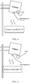
- FIG. 1 is a diagram of an application scenario of an adjustment apparatus 100.
- the adjustment apparatus 100 provided in this embodiment of this application is mounted on an antenna, and the antenna is usually mounted on a pole or a tower, to be in communication connection with a base transceiver station (Base Transceiver Station, BTS).
- BTS Base Transceiver Station
- the base transceiver station BTS is generally referred to as a base station for short, is a part that is in a network and that enables a terminal to access a wireless network, and may also be referred to as a radio access network (Radio Access Network, RAN) node; or a node or a device that enables a terminal to access a wireless network.
- Radio Access Network Radio Access Network
- the base station described in this application may alternatively be another radio access network node, for example, may be a transmission reception point (Transmission Reception Point, TRP), an evolved NodeB (evolved Node B, eNB), a radio network controller (radio network controller, RNC), a NodeB (Node B, NB), a base station controller (Base Station Controller, BSC), a home base station (for example, Home evolved NodeB or Home Node B, HNB), a baseband unit (BaseBand Unit, BBU), or a Wi-Fi access point (Access Point, AP).
- TRP Transmission Reception Point
- eNB evolved NodeB
- RNC radio network controller
- NodeB NodeB
- BSC Base Station Controller
- BSC Base Station Controller
- HNB Home evolved NodeB or Home Node B, HNB
- BBU Baseband unit
- Wi-Fi access point Access Point, AP
- the adjustment apparatus 100 shown in the figure is mounted inside the antenna.
- the adjustment apparatus 100 may alternatively be mounted outside the antenna (not shown in FIG. 1 ).
- one part of the adjustment apparatus may be mounted inside the antenna and the other part of the adjustment apparatus may be mounted outside the antenna (not shown in FIG. 1 ).
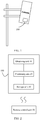
- FIG. 2 is a schematic diagram of a structure of an adjustment apparatus 100 according to an embodiment of this application.
- the adjustment apparatus 100 includes a processing unit 20, a storage unit 30, and an obtaining unit 40.
- the processing unit 20 is electrically connected to the obtaining unit 30 and the storage unit 30.
- the obtaining unit 40 is configured to obtain a signal of antenna position information.
- the antenna position information is information that can be processed and calculated to obtain an antenna position.
- the processing unit 20 is configured to obtain, through processing, latitude and longitude of an antenna or an azimuth of the antenna based on the antenna position information in the signal.
- the processing unit 20 is further configured to adjust an electrical downtilt of the antenna according to an instruction of a remote control unit 50.
- the control unit 50 is configured to send the instruction to control and adjust the processing unit 20, for example, control the processing unit 20 to read and write the storage unit 30, and for another example, control the processing unit 20 to adjust the antenna downtilt.
- the storage unit 30 is configured to store the latitude and longitude of the antenna or the azimuth of the antenna.
- the processing unit 20 is further configured to read and write the latitude and longitude of the antenna or the azimuth of the antenna in the storage unit 30 according to the instruction of the remote control unit 50.
- the adjustment apparatus provided in this embodiment of this application can adjust the electrical downtilt of the antenna, and can further obtain the latitude and longitude, and the azimuth from one or more antenna engineering parameters in real time.
- the apparatus integrates the two functions, thereby reducing costs of the adjustment apparatus.
- the obtaining unit 40 is a global positioning system (Global Positioning System, GPS) antenna.
- the GPS antenna is configured to obtain a satellite signal of the antenna.
- the processing unit 20 obtains, through processing, the latitude and longitude, and the azimuth of the antenna based on the satellite signal received by the GPS antenna.
- the processing unit 20 may be a global navigation satellite system (Global Navigation Satellite System, GNSS) receiver, such as a satellite card.
- GNSS Global Navigation Satellite System
- the obtaining unit 40 may alternatively be another apparatus, for example, a BeiDou positioning related apparatus.
- the processing unit 20 may be a BeiDou positioning apparatus or a BeiDou positioning chip. This is merely an example herein, and this is not limited in this application.
- the processing unit 20 includes an active component.
- the processing unit 20 includes one or more of a global navigation satellite system GNSS receiver, an amplifier, an acceleration sensor, and a temperature sensor. It is well known to a person skilled in the art that the active component is easily damaged. Therefore, in the adjustment apparatus provided in this embodiment of this application, the active component is integrated into the processing unit. When the active component needs to be replaced, only the processing unit needs to be replaced, and the entire adjustment apparatus does not need to be replaced, so that replacement costs can be greatly reduced.
- the acceleration sensor is configured to obtain, through measurement, a mechanical downtilt of the antenna and/or an altitude of the antenna. Therefore, the adjustment apparatus 100 provided in this embodiment of this application may further obtain the mechanical downtilt of the antenna and/or the altitude of the antenna from the one or more antenna engineering parameters.
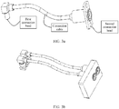
- FIG. 3a is a schematic diagram of a structure of a pluggable radio frequency connector according to an embodiment of this application.
- the pluggable radio frequency connector 300 includes a first connection head and a second connection head, and a connection cable used to connect the first connection head and the second connection head.
- the two connection heads (the first connection head and the second connection head) included in the pluggable radio frequency connector 300 have different structures, but both have connection head structures that are easily inserted and removed.
- the two connection heads may alternatively have a same structure (not shown in FIG. 3a ). This is not limited in this application.
- the first connection head or the second connection head may alternatively be a connection head of another structure.
- the connection cable shown in FIG. 3a is a coaxial cable, and the connection cable may alternatively be another radio frequency connection cable. This is not limited in this application.
- the first connection head and the second connection head of the pluggable radio frequency connector may alternatively be directly connected to each other without any connection cable between the two connection heads (not shown in the figure).
- the pluggable connection described in this application includes direct pluggable connection or pluggable connection through screwing.
- the pluggable radio frequency connector provided in the embodiments of this application further includes a structural form shown in FIG. 3b.
- FIG. 3b is a schematic diagram of a structure in which two pluggable radio frequency connectors shown in FIG. 3a are fastened as a whole.
- the processing unit 20 is electrically connected to the obtaining unit 40 and the storage unit 30 through the pluggable radio frequency connector, to communicate with each other, and is easily connected to or disconnected from the obtaining unit 40 and the storage unit 30.
- the processing unit 20 is in pluggable connection with the antenna.
- the processing unit 20 is in pluggable connection with the inside of the antenna, or the processing unit 20 is in pluggable connection with the outside of the antenna.
- the adjustment apparatus 100 when the adjustment apparatus 100 is in pluggable connection with the inside of the antenna, the adjustment apparatus 100 may communicate with the remote control unit 50 by sharing an antenna radio frequency port. Therefore, no antenna radio frequency port is increased because of addition of the adjustment apparatus. In addition, it is easy to mount and remove the entire adjustment apparatus 100, so that the adjustment apparatus is easily used.
- the adjustment apparatus 100 when the adjustment apparatus 100 may alternatively be in pluggable connection with the outside of the antenna, the adjustment apparatus 100 may also communicate with the remote control unit 50 by sharing the antenna radio frequency port. Therefore, no antenna radio frequency port is increased because of addition of the adjustment apparatus. In addition, it is easy to mount and remove the entire adjustment apparatus 100, so that the adjustment apparatus is easily used.
- the adjustment apparatus 100 when one part of the adjustment apparatus 100 is mounted inside the antenna and the other part of the adjustment apparatus is mounted outside the antenna, as shown in FIG. 6 , the processing unit 20 of the adjustment apparatus 100 is outside the antenna, and another unit, for example, the storage unit 30, of the adjustment apparatus 100 is inside the antenna, the adjustment apparatus 100 may communicate with the remote control unit 50 directly through a port of the processing unit 20. Similarly, no antenna radio frequency port is increased because of addition of the adjustment apparatus 100. In addition, it is easy to mount and remove the entire adjustment apparatus 100, so that the adjustment apparatus is easily used.
- the storage unit 30 is mounted outside the antenna, and the processor 20 is mounted inside the antenna (not shown in FIG. 6 ). In this case, the adjustment apparatus 100 may communicate with the remote control unit 50 through a port of the storage unit 30. This is not limited in this application.
- adjustment apparatus 100 shown in FIG. 4 to FIG. 6 is merely an example, and the adjustment apparatus provided in the embodiments of this application includes but is not limited to the shown adjustment apparatus 100.
- the storage unit 30 provided in this embodiment of this application is further configured to store antenna information of the antenna.
- the antenna information includes one or more of an antenna model, an antenna electronic label, an antenna frequency band, an antenna beam width, an antenna gain, antenna configuration data, and an antenna serial number.
- the storage unit 30 is further configured to store a procedure parameter, such as a weight value, a phase, a movement length of a transmission part in a phase shifter, or a movement manner of the transmission part in the phase shifter, for adjusting the antenna downtilt.
- a procedure parameter such as a weight value, a phase, a movement length of a transmission part in a phase shifter, or a movement manner of the transmission part in the phase shifter, for adjusting the antenna downtilt.
- the remote control unit 50 shown in FIG. 4 to FIG. 6 may be mounted in a base station, for example, a baseband processing unit or a radio frequency processing unit of the base station; or the remote control unit 50 may be a portable control unit (portable control unit, PCU); or the remote control unit 50 may be a separate terminal device.
- the adjustment apparatus 100 may communicate with the remote control unit 50 in a wireless or wired manner.
- the terminal device is also referred to as user equipment (user equipment, UE), a mobile station (mobile station, MS), a mobile terminal (mobile terminal, MT), or the like, and is a device that provides voice and/or data connectivity for a user, for example, a handheld device or a vehicle-mounted device having a wireless connection function.
- examples of some terminals are: a mobile phone (mobile phone), a tablet computer, a notebook computer, a palmtop computer, a mobile internet device (mobile internet device, MID), a wearable device, a virtual reality (virtual reality, VR) device, an augmented reality (augmented reality, AR) device, a wireless terminal in industrial control (industrial control), a wireless terminal in self driving (self driving), a wireless terminal in a remote surgery (remote medical surgery), a wireless terminal in a smart grid (smart grid), a wireless terminal in transportation safety (transportation safety), a wireless terminal in a smart city (smart city), a wireless terminal in a smart home (smart home), and the like.
- FIG. 7 to FIG. 9 each are a schematic diagram of a structure of an adjustment apparatus 100 according to an embodiment of this application.
- FIG. 8 and FIG. 9 are partial enlarged and exploded views of FIG. 7 .
- the adjustment apparatus 100 includes a processing unit 20, a storage unit 30, and an obtaining unit 40.
- FIG. 7 further includes an antenna 700.
- the antenna 700 shown in FIG. 7 includes a radio frequency port 710, a reflection panel 720, a phase shifter transmission module 730, and a phase shifter 740.
- the antenna 700 may further include a radome 750 (not shown in FIG. 7 ).
- the processing unit 20 includes an integrated chip 910, and the processing unit 20 is mounted on the reflection panel 720 of the antenna in a pluggable manner.
- the processing unit 20 may alternatively be in another structure form. This is not limited in this application.
- the processing unit 20 is electrically connected to the storage unit 30 through a pluggable radio frequency connector 920.
- the storage unit 30 is electrically connected to the obtaining unit 40 through a pluggable radio frequency connector 930.
- the pluggable radio frequency connector 930 is the pluggable radio frequency connector shown in FIG. 3b ; or the storage unit 30 is electrically connected to the obtaining unit 40 directly via a pluggable coaxial cable of the pluggable radio frequency connector 930.
- the obtaining unit 40 shown in FIG. 7 is mounted on an upper end of the antenna 700 by using a bracket 760.
- the upper end of the antenna 700 is an end away from an antenna radio frequency port, and a lower end of the antenna 700 is an end of the antenna radio frequency port.
- the obtaining unit 40 shown in FIG. 7 is two GPS antennas. Satellite signals are received through the two GPS antennas.
- the processing unit 20 performs processing such as filtering and power amplification on two GPS signals, and obtains antenna position information from the two GPS signals.
- the antenna position information is a distance difference between the two GPS signals during propagation. In this case, latitude and longitude, and an azimuth of the antenna are obtained by processing the signals and calculating the distance difference between the signals.
- the processing unit 20 may further drive the phase shifter transmission module 730 by controlling a motor 940 shown in FIG. 9 , to control a working status of a phase shifter 740, so as to adjust an electrical downtilt of the antenna.
- the processing unit 20 is further configured to read and write the latitude and longitude of the antenna or the azimuth of the antenna in the storage unit 30 according to an instruction of a remote control unit 50, to measure and obtain one or more antenna engineering parameters in real time.
- the engineering parameters include the latitude and longitude of the antenna and the azimuth of the antenna.
- the acceleration sensor is configured to obtain, through measurement, a mechanical downtilt of the antenna and/or an altitude of the antenna
- the adjustment apparatus may further obtain the following two engineering parameters: the mechanical downtilt of the antenna and/or the altitude of the antenna.
- adjustment apparatus shown in FIG. 7 to FIG. 9 is merely an implementation, and the adjustment apparatus provided in this application includes but is not limited thereto.
- the adjustment apparatus 100 may communicate with the remote control unit by sharing the antenna radio frequency port 710, or may communicate with the remote control unit through a port 210 of the processing unit 20 of the adjustment apparatus 100.
- the adjustment apparatus 100 may alternatively communicate with the remote control unit through another port. This is not limited in this application.
- the adjustment of the antenna downtilt and the real-time obtaining of the one or more antenna engineering parameters are integrated into the adjustment apparatus shown in FIG. 7 to FIG. 9 for controlling and processing.
- the apparatus integrates the two functions, thereby reducing costs of the adjustment apparatus.
- the adjustment apparatus can remotely adjust the electrical downtilt of the antenna, and can further obtain the antenna engineering parameter in real time.
- all active components such as a power amplifier, an amplifier, and an acceleration sensor
- efficient maintenance can be performed when necessary, thereby reducing maintenance costs.
- the antenna engineering parameter can be obtained in real time, a beam radiated by the antenna can be corrected based on a most real antenna attitude of the antenna, thereby helping improve network coverage of a communications network.
- An embodiment of this application further provides an antenna, including the adjustment apparatus according to any one of the foregoing implementations.
- An embodiment of this application further provides a communications device, including the adjustment apparatus according to any one of the foregoing implementations and/or the foregoing antenna.
Landscapes
- Engineering & Computer Science (AREA)
- Computer Networks & Wireless Communication (AREA)
- Signal Processing (AREA)
- Variable-Direction Aerials And Aerial Arrays (AREA)
Applications Claiming Priority (2)
| Application Number | Priority Date | Filing Date | Title |
|---|---|---|---|
| CN201811157810.2A CN110970731A (zh) | 2018-09-30 | 2018-09-30 | 调节装置、天线及通信设备 |
| PCT/CN2019/107346 WO2020063545A1 (zh) | 2018-09-30 | 2019-09-23 | 调节装置、天线及通信设备 |
Publications (2)
| Publication Number | Publication Date |
|---|---|
| EP3843214A1 true EP3843214A1 (de) | 2021-06-30 |
| EP3843214A4 EP3843214A4 (de) | 2021-11-10 |
Family
ID=69950302
Family Applications (1)
| Application Number | Title | Priority Date | Filing Date |
|---|---|---|---|
| EP19866578.8A Pending EP3843214A4 (de) | 2018-09-30 | 2019-09-23 | Justiervorrichtung, antenne und kommunikationsvorrichtung |
Country Status (5)
| Country | Link |
|---|---|
| US (1) | US12080951B2 (de) |
| EP (1) | EP3843214A4 (de) |
| CN (1) | CN110970731A (de) |
| BR (1) | BR112021005512A2 (de) |
| WO (1) | WO2020063545A1 (de) |
Families Citing this family (3)
| Publication number | Priority date | Publication date | Assignee | Title |
|---|---|---|---|---|
| CN112383929A (zh) * | 2020-11-04 | 2021-02-19 | 中国联合网络通信集团有限公司 | 天线调整设备、方法及计算机可读存储介质 |
| CN114552214B (zh) | 2020-11-24 | 2024-12-27 | 华为技术有限公司 | 天线系统 |
| CN119401099A (zh) * | 2024-10-31 | 2025-02-07 | 中国电信股份有限公司 | 基站天线及具有其的蜂窝网络基站 |
Family Cites Families (30)
| Publication number | Priority date | Publication date | Assignee | Title |
|---|---|---|---|---|
| DE10104564C1 (de) | 2001-02-01 | 2002-09-19 | Kathrein Werke Kg | Steuerungsvorrichtung zum Einstellen eines unterschiedlichen Absenkwinkels insbesondere von zu einer Basisstation gehörenden Mobilfunkantennen sowie eine zugehörige Antenne und Verfahren zur Veränderung eines Absenkwinkels |
| US7236808B2 (en) * | 2002-09-09 | 2007-06-26 | Interdigital Technology Corporation | Vertical dynamic beam-forming |
| US20090141623A1 (en) * | 2007-11-27 | 2009-06-04 | Hyun Jung | Central Antenna Management System With Centralized Database |
| EP2196817B1 (de) * | 2008-12-10 | 2016-04-27 | Alcatel Lucent | Antennenmesssystem und zugehöriges Verfahren |
| US8412272B2 (en) * | 2009-07-24 | 2013-04-02 | T-Mobile Usa, Inc. | Rectifier circuit management system, such as for use in cell site power systems |
| DE102010012991B4 (de) | 2010-03-26 | 2011-12-15 | Kathrein-Werke Kg | Multi-Strahlformeinrichtung |
| US8391926B2 (en) | 2010-03-26 | 2013-03-05 | Kathrein-Werke Kg | Multi-beam-shaping structure |
| US8193983B1 (en) * | 2010-10-05 | 2012-06-05 | Farmer Michael K | Automated antenna alignment system |
| CN104966902B (zh) * | 2010-11-23 | 2017-11-21 | 华为技术有限公司 | 天线装置、天线系统和天线电调方法 |
| DE102011006424A1 (de) * | 2011-03-30 | 2012-10-04 | Dr. Johannes Heidenhain Gmbh | Positionsmesseinrichtung |
| DE102011015572B3 (de) * | 2011-03-30 | 2012-06-28 | Kathrein-Werke Kg | Strahlformeinrichtung für eine Antenne sowie zugehörige Antenne |
| CN102170321A (zh) * | 2011-04-20 | 2011-08-31 | 李英祥 | 一种基站天线参数监测仪及自动监测方法 |
| US9294932B2 (en) * | 2011-07-21 | 2016-03-22 | Qualcomm Incorporated | Apparatus and method for wireless network enhancement via variable down tilt |
| CN102401645B (zh) * | 2011-10-03 | 2013-11-06 | 西安三元达海天天线有限公司 | 室外天线姿态检测装置及检测方法 |
| CN102509902B (zh) * | 2011-11-21 | 2014-05-07 | 华为技术有限公司 | 一种基站天线信息的获取方法、装置及基站天线 |
| CN102655269A (zh) * | 2012-04-20 | 2012-09-05 | 广东通宇通讯股份有限公司 | 基于方位校正调节的电调天线 |
| JP6125638B2 (ja) * | 2012-09-14 | 2017-05-10 | ケーエムダブリュ・インコーポレーテッド | 移動通信基地局のアンテナ及びその制御方法 |
| CN102946004B (zh) * | 2012-11-27 | 2016-01-20 | 长沙威佳通信科技有限公司 | 天线调整方法和装置 |
| DE102013000944A1 (de) * | 2013-01-19 | 2014-07-24 | Daimler Ag | Lenkrad mit verbesserter Schnittstelle zu einem Fingernavigationsmodul |
| JP6291052B2 (ja) * | 2013-08-09 | 2018-03-14 | 華為技術有限公司Huawei Technologies Co.,Ltd. | 複数の事業者と無線周波数およびデジタル変換ユニットとの間でアンテナを共有するための方法およびシステム |
| CN103840262B (zh) * | 2014-03-07 | 2017-04-26 | 华为技术有限公司 | 调节天线的方法、天线和基站控制中心 |
| US9596617B2 (en) * | 2015-04-14 | 2017-03-14 | ETAK Systems, LLC | Unmanned aerial vehicle-based systems and methods associated with cell sites and cell towers |
| ES2550133B1 (es) * | 2015-07-07 | 2016-09-09 | Telnet Redes Inteligentes, S.A. | Antena multi-haz para estación base de telefonía móvil |
| US9788282B2 (en) * | 2015-11-30 | 2017-10-10 | Veniam, Inc. | Systems and methods for improving fixed access point coverage in a network of moving things |
| US9942749B2 (en) * | 2015-10-26 | 2018-04-10 | Time Warner Cable Enterprises Llc | Methods and apparatus for managing and/or configuring base stations which include sensors |
| CN105846039A (zh) * | 2016-03-18 | 2016-08-10 | 京信通信技术(广州)有限公司 | 天线及其姿态数据获取装置、监控系统和方法 |
| WO2017192714A1 (en) * | 2016-05-04 | 2017-11-09 | Commscope Technologies Llc | System and method of adjusting antenna beam on antenna tower |
| US10511090B2 (en) * | 2016-07-11 | 2019-12-17 | Sentenia Systems, Inc. | Wireless telecommunication antenna mount and control system |
| US10645604B2 (en) * | 2018-06-04 | 2020-05-05 | Verizon Patent And Licensing Inc. | Intelligent optimization of cells in a mobile network |
| EP4027542B1 (de) * | 2019-09-25 | 2024-08-21 | Huawei Technologies Co., Ltd. | Verfahren und system zur zeilenfolgedetektion |
-
2018
- 2018-09-30 CN CN201811157810.2A patent/CN110970731A/zh active Pending
-
2019
- 2019-09-23 EP EP19866578.8A patent/EP3843214A4/de active Pending
- 2019-09-23 BR BR112021005512-6A patent/BR112021005512A2/pt unknown
- 2019-09-23 WO PCT/CN2019/107346 patent/WO2020063545A1/zh not_active Ceased
-
2021
- 2021-03-29 US US17/215,768 patent/US12080951B2/en active Active
Also Published As
| Publication number | Publication date |
|---|---|
| US12080951B2 (en) | 2024-09-03 |
| US20210218139A1 (en) | 2021-07-15 |
| WO2020063545A1 (zh) | 2020-04-02 |
| BR112021005512A2 (pt) | 2021-06-22 |
| EP3843214A4 (de) | 2021-11-10 |
| CN110970731A (zh) | 2020-04-07 |
Similar Documents
| Publication | Publication Date | Title |
|---|---|---|
| US12080951B2 (en) | Adjustment apparatus, antenna, and communications device | |
| US11817618B2 (en) | Directional wireless hotspot device and method for pointing a directional antenna | |
| EP2784533B1 (de) | Verfahren und vorrichtung zur erfassung von informationen über eine basisstationsantenne und basisstationsantenne | |
| EP3059603A1 (de) | Antennenazimut-ausrichtungsmonitor | |
| US9046601B2 (en) | Handheld antenna attitude measuring system | |
| US10165451B1 (en) | Controlling coverage in a wireless communications network | |
| CN109581080B (zh) | 用于评估短波天线性能的空中测试设备 | |
| WO2022113531A1 (ja) | 端末装置の位置を特定するシステム、無線中継装置、情報処理装置及び方法 | |
| US20110285584A1 (en) | Handheld Antenna Attitude Measuring System | |
| CN110086843A (zh) | 一种监测方法及终端 | |
| US9979083B2 (en) | Radio equipment positioning | |
| TW202510527A (zh) | 對星方法、終端設備和電腦可讀儲存介質 | |
| CN106911342A (zh) | 浮空无线信号收发装置、系统以及角度调整方法 | |
| CN210604994U (zh) | 一种天线姿态远程监测模块和系统 | |
| EP4716231A1 (de) | Basisstationsantennensystem | |
| CN213179956U (zh) | 无线通讯基站的天线工参测量系统及天线系统 | |
| US20260128503A1 (en) | Base station antenna system | |
| JP7854743B1 (ja) | 電波発生源の探知方法および探知システム | |
| CN206226444U (zh) | 一种参数测试模组和用于基站天线的参数测试系统 | |
| CN215494160U (zh) | 一种多星标定位置的设备 | |
| CA3067734C (en) | Directional wireless hotspot device and method for pointing a directional antenna | |
| KR20260034360A (ko) | 5g nr 기지국 방사 빔 패턴측정장치 | |
| JP2012161031A (ja) | 基地局及び基地局の自律設定方法 | |
| JP2014096665A (ja) | 自立構成型アレーアンテナシステム及びアレーアンテナ構成方法 | |
| JP2012175540A (ja) | 基地局及び基地局の自律設定方法 |
Legal Events
| Date | Code | Title | Description |
|---|---|---|---|
| STAA | Information on the status of an ep patent application or granted ep patent |
Free format text: STATUS: THE INTERNATIONAL PUBLICATION HAS BEEN MADE |
|
| PUAI | Public reference made under article 153(3) epc to a published international application that has entered the european phase |
Free format text: ORIGINAL CODE: 0009012 |
|
| STAA | Information on the status of an ep patent application or granted ep patent |
Free format text: STATUS: REQUEST FOR EXAMINATION WAS MADE |
|
| 17P | Request for examination filed |
Effective date: 20210322 |
|
| AK | Designated contracting states |
Kind code of ref document: A1 Designated state(s): AL AT BE BG CH CY CZ DE DK EE ES FI FR GB GR HR HU IE IS IT LI LT LU LV MC MK MT NL NO PL PT RO RS SE SI SK SM TR |
|
| A4 | Supplementary search report drawn up and despatched |
Effective date: 20211011 |
|
| RIC1 | Information provided on ipc code assigned before grant |
Ipc: H01Q 3/02 20060101ALI20211005BHEP Ipc: H01Q 1/12 20060101ALI20211005BHEP Ipc: H01Q 3/26 20060101ALI20211005BHEP Ipc: H01Q 1/00 20060101ALI20211005BHEP Ipc: H01Q 3/32 20060101AFI20211005BHEP |
|
| DAV | Request for validation of the european patent (deleted) | ||
| DAX | Request for extension of the european patent (deleted) | ||
| STAA | Information on the status of an ep patent application or granted ep patent |
Free format text: STATUS: EXAMINATION IS IN PROGRESS |
|
| RIC1 | Information provided on ipc code assigned before grant |
Ipc: H01Q 3/00 20060101ALI20250317BHEP Ipc: H01Q 3/02 20060101ALI20250317BHEP Ipc: H01Q 1/12 20060101ALI20250317BHEP Ipc: H01Q 3/26 20060101ALI20250317BHEP Ipc: H01Q 1/00 20060101ALI20250317BHEP Ipc: H01Q 3/32 20060101AFI20250317BHEP |
|
| 17Q | First examination report despatched |
Effective date: 20250331 |