EP3843230A1 - Agencement d'infrastructure de charge destiné à la charge des véhicules électriques et procédé de fonctionnement associé - Google Patents
Agencement d'infrastructure de charge destiné à la charge des véhicules électriques et procédé de fonctionnement associé Download PDFInfo
- Publication number
- EP3843230A1 EP3843230A1 EP20215866.3A EP20215866A EP3843230A1 EP 3843230 A1 EP3843230 A1 EP 3843230A1 EP 20215866 A EP20215866 A EP 20215866A EP 3843230 A1 EP3843230 A1 EP 3843230A1
- Authority
- EP
- European Patent Office
- Prior art keywords
- charging
- phase
- supply system
- unbalanced load
- conductor
- Prior art date
- Legal status (The legal status is an assumption and is not a legal conclusion. Google has not performed a legal analysis and makes no representation as to the accuracy of the status listed.)
- Pending
Links
Images



Classifications
-
- H—ELECTRICITY
- H02—GENERATION; CONVERSION OR DISTRIBUTION OF ELECTRIC POWER
- H02J—ELECTRIC POWER NETWORKS; CIRCUIT ARRANGEMENTS OR SYSTEMS FOR SUPPLYING OR DISTRIBUTING ELECTRIC POWER; SYSTEMS FOR STORING ELECTRIC ENERGY
- H02J3/00—Circuit arrangements for AC mains or AC distribution networks
- H02J3/26—Arrangements for eliminating or reducing asymmetry in polyphase networks
-
- B—PERFORMING OPERATIONS; TRANSPORTING
- B60—VEHICLES IN GENERAL
- B60L—PROPULSION OF ELECTRICALLY-PROPELLED VEHICLES; SUPPLYING ELECTRIC POWER FOR AUXILIARY EQUIPMENT OF ELECTRICALLY-PROPELLED VEHICLES; ELECTRODYNAMIC BRAKE SYSTEMS FOR VEHICLES IN GENERAL; MAGNETIC SUSPENSION OR LEVITATION FOR VEHICLES; MONITORING OPERATING VARIABLES OF ELECTRICALLY-PROPELLED VEHICLES; ELECTRIC SAFETY DEVICES FOR ELECTRICALLY-PROPELLED VEHICLES
- B60L53/00—Methods of charging batteries, specially adapted for electric vehicles; Charging stations or on-board charging equipment therefor; Exchange of energy storage elements in electric vehicles
- B60L53/60—Monitoring or controlling charging stations
- B60L53/63—Monitoring or controlling charging stations in response to network capacity
-
- B—PERFORMING OPERATIONS; TRANSPORTING
- B60—VEHICLES IN GENERAL
- B60L—PROPULSION OF ELECTRICALLY-PROPELLED VEHICLES; SUPPLYING ELECTRIC POWER FOR AUXILIARY EQUIPMENT OF ELECTRICALLY-PROPELLED VEHICLES; ELECTRODYNAMIC BRAKE SYSTEMS FOR VEHICLES IN GENERAL; MAGNETIC SUSPENSION OR LEVITATION FOR VEHICLES; MONITORING OPERATING VARIABLES OF ELECTRICALLY-PROPELLED VEHICLES; ELECTRIC SAFETY DEVICES FOR ELECTRICALLY-PROPELLED VEHICLES
- B60L53/00—Methods of charging batteries, specially adapted for electric vehicles; Charging stations or on-board charging equipment therefor; Exchange of energy storage elements in electric vehicles
- B60L53/60—Monitoring or controlling charging stations
- B60L53/67—Controlling two or more charging stations
-
- Y—GENERAL TAGGING OF NEW TECHNOLOGICAL DEVELOPMENTS; GENERAL TAGGING OF CROSS-SECTIONAL TECHNOLOGIES SPANNING OVER SEVERAL SECTIONS OF THE IPC; TECHNICAL SUBJECTS COVERED BY FORMER USPC CROSS-REFERENCE ART COLLECTIONS [XRACs] AND DIGESTS
- Y02—TECHNOLOGIES OR APPLICATIONS FOR MITIGATION OR ADAPTATION AGAINST CLIMATE CHANGE
- Y02E—REDUCTION OF GREENHOUSE GAS [GHG] EMISSIONS, RELATED TO ENERGY GENERATION, TRANSMISSION OR DISTRIBUTION
- Y02E40/00—Technologies for an efficient electrical power generation, transmission or distribution
- Y02E40/50—Arrangements for eliminating or reducing asymmetry in polyphase networks
-
- Y—GENERAL TAGGING OF NEW TECHNOLOGICAL DEVELOPMENTS; GENERAL TAGGING OF CROSS-SECTIONAL TECHNOLOGIES SPANNING OVER SEVERAL SECTIONS OF THE IPC; TECHNICAL SUBJECTS COVERED BY FORMER USPC CROSS-REFERENCE ART COLLECTIONS [XRACs] AND DIGESTS
- Y02—TECHNOLOGIES OR APPLICATIONS FOR MITIGATION OR ADAPTATION AGAINST CLIMATE CHANGE
- Y02E—REDUCTION OF GREENHOUSE GAS [GHG] EMISSIONS, RELATED TO ENERGY GENERATION, TRANSMISSION OR DISTRIBUTION
- Y02E60/00—Enabling technologies; Technologies with a potential or indirect contribution to GHG emissions mitigation
-
- Y—GENERAL TAGGING OF NEW TECHNOLOGICAL DEVELOPMENTS; GENERAL TAGGING OF CROSS-SECTIONAL TECHNOLOGIES SPANNING OVER SEVERAL SECTIONS OF THE IPC; TECHNICAL SUBJECTS COVERED BY FORMER USPC CROSS-REFERENCE ART COLLECTIONS [XRACs] AND DIGESTS
- Y02—TECHNOLOGIES OR APPLICATIONS FOR MITIGATION OR ADAPTATION AGAINST CLIMATE CHANGE
- Y02T—CLIMATE CHANGE MITIGATION TECHNOLOGIES RELATED TO TRANSPORTATION
- Y02T10/00—Road transport of goods or passengers
- Y02T10/60—Other road transportation technologies with climate change mitigation effect
- Y02T10/70—Energy storage systems for electromobility, e.g. batteries
-
- Y—GENERAL TAGGING OF NEW TECHNOLOGICAL DEVELOPMENTS; GENERAL TAGGING OF CROSS-SECTIONAL TECHNOLOGIES SPANNING OVER SEVERAL SECTIONS OF THE IPC; TECHNICAL SUBJECTS COVERED BY FORMER USPC CROSS-REFERENCE ART COLLECTIONS [XRACs] AND DIGESTS
- Y02—TECHNOLOGIES OR APPLICATIONS FOR MITIGATION OR ADAPTATION AGAINST CLIMATE CHANGE
- Y02T—CLIMATE CHANGE MITIGATION TECHNOLOGIES RELATED TO TRANSPORTATION
- Y02T10/00—Road transport of goods or passengers
- Y02T10/60—Other road transportation technologies with climate change mitigation effect
- Y02T10/7072—Electromobility specific charging systems or methods for batteries, ultracapacitors, supercapacitors or double-layer capacitors
-
- Y—GENERAL TAGGING OF NEW TECHNOLOGICAL DEVELOPMENTS; GENERAL TAGGING OF CROSS-SECTIONAL TECHNOLOGIES SPANNING OVER SEVERAL SECTIONS OF THE IPC; TECHNICAL SUBJECTS COVERED BY FORMER USPC CROSS-REFERENCE ART COLLECTIONS [XRACs] AND DIGESTS
- Y02—TECHNOLOGIES OR APPLICATIONS FOR MITIGATION OR ADAPTATION AGAINST CLIMATE CHANGE
- Y02T—CLIMATE CHANGE MITIGATION TECHNOLOGIES RELATED TO TRANSPORTATION
- Y02T90/00—Enabling technologies or technologies with a potential or indirect contribution to GHG emissions mitigation
- Y02T90/10—Technologies relating to charging of electric vehicles
- Y02T90/12—Electric charging stations
-
- Y—GENERAL TAGGING OF NEW TECHNOLOGICAL DEVELOPMENTS; GENERAL TAGGING OF CROSS-SECTIONAL TECHNOLOGIES SPANNING OVER SEVERAL SECTIONS OF THE IPC; TECHNICAL SUBJECTS COVERED BY FORMER USPC CROSS-REFERENCE ART COLLECTIONS [XRACs] AND DIGESTS
- Y04—INFORMATION OR COMMUNICATION TECHNOLOGIES HAVING AN IMPACT ON OTHER TECHNOLOGY AREAS
- Y04S—SYSTEMS INTEGRATING TECHNOLOGIES RELATED TO POWER NETWORK OPERATION, COMMUNICATION OR INFORMATION TECHNOLOGIES FOR IMPROVING THE ELECTRICAL POWER GENERATION, TRANSMISSION, DISTRIBUTION, MANAGEMENT OR USAGE, i.e. SMART GRIDS
- Y04S10/00—Systems supporting electrical power generation, transmission or distribution
- Y04S10/12—Monitoring or controlling equipment for energy generation units, e.g. distributed energy generation [DER] or load-side generation
- Y04S10/126—Monitoring or controlling equipment for energy generation units, e.g. distributed energy generation [DER] or load-side generation the energy generation units being or involving electric vehicles [EV] or hybrid vehicles [HEV], i.e. power aggregation of EV or HEV, vehicle to grid arrangements [V2G]
Definitions
- the invention relates to a charging infrastructure arrangement for charging electric vehicles with at least one AC charging point, which is connected via a three-phase supply system with three phase conductors and a neutral conductor to a connection point which is set up to connect the charging infrastructure arrangement to an external supply network.
- the invention also relates to an operating method for a charging infrastructure arrangement for charging electric vehicles.
- comparatively high charging currents are provided for charging electric vehicles.
- the high charging currents and the associated services can put a considerable strain on a supply network. This applies in particular when a plurality of charging points are connected to the supply network in one connection point and the charging points are also used to charge electric vehicles.
- the unbalanced load is understood as the sum of all loads on the phase conductors at the connection point based on the currents or the powers, formed by vectorial addition. For example, the unbalanced load is zero if the load is symmetrical and the current or power amplitude is the same for all phases.
- various charging points within a charging infrastructure arrangement are usually connected to different phase conductors of the three-phase supply system. In this way, it can be achieved that the load when charging the vehicles is distributed as possible to different phase conductors and one phase conductor is not excessively loaded. Furthermore, depending on the current load situation, individual charging points can be switched off if the phase conductor assigned to them is too heavily loaded.
- the charging current for the most recently added electric vehicles can be reduced in order to comply with the limit value with regard to the current-carrying capacity, or provision is made for the charging current to be reduced proportionally for several or all vehicles.
- the charging current for individual or all electric vehicles can be reduced if, for example, the load in a phase conductor is reduced by ending a charging process and the unbalanced load at the connection point of the charging infrastructure arrangement increases as a result.
- the object of the present invention is to specify an improved charging infrastructure arrangement and an operating method for this, which counteract the aforementioned problems.
- the charging infrastructure arrangement comprises for charging Electric vehicles have a connection point that is set up to connect the charging infrastructure arrangement to an external supply network, a three-phase current supply system with three phase conductors and a neutral conductor, at least one AC charging point that is connected to at least or precisely one phase conductor of the three-phase supply system and the Neutral conductor is connected, as well as an unbalanced load compensation unit, which is connected to the three-phase supply system via connecting conductors.
- a maximum current-carrying capacity and / or a maximum unbalanced load are specified for the connection point.
- the unbalanced load compensation unit is set up to receive information about an accumulated load on each phase conductor of the three-phase supply system due to the sum of the AC charging points and / or a local load on the three-phase supply system due to each individual AC charging point and for impressing an equalizing current between the phase conductors of the Three-phase supply system in such a way that the limit values for the maximum unbalanced load and / or the maximum current carrying capacity are not exceeded at the connection point.
- the local and / or cumulative load on the three-phase supply system by the AC charging points can be determined, for example, via the load current, which includes the active current and the reactive current.
- the local and / or cumulative load can be determined via the apparent power.
- Apparent power includes active power and reactive power.
- the particular advantage of the invention is that by providing the unbalanced load compensation unit within the charging infrastructure arrangement, the load on the phase conductors of the three-phase supply system can be balanced with the result that peak loads can be avoided or distributed in such a way that an actual unbalanced load at the connection point of the charging infrastructure arrangement is lower is than the maximum unbalanced load that is still permissible, which is 20 A or 4.6 kVA, respectively, for various network operators in Germany.
- energy is taken from the least loaded phases or phase conductors of the three-phase supply system in order to distribute it to the more heavily loaded phases or phase conductors.
- all phase conductors are loaded equally, i.e. the load currents in all phase conductors are the same.
- the unbalanced load compensation unit provides a controller and power electronics with a bridge circuit.
- the bridge circuit comprises a bridge branch for each phase conductor or for each connection conductor, which is assigned to a phase conductor of the three-phase supply line system, and an intermediate circuit with an intermediate circuit capacitance, which can include a plurality of capacitors.
- a very inexpensive implementation of the bridge circuit results when the neutral conductor or a connection conductor of the unbalanced load compensation unit assigned to the neutral conductor of the three-phase supply system is connected to a center point of the intermediate circuit capacitance.
- the bridge circuit can provide a further bridge branch for the connection conductor assigned to the neutral conductor of the three-phase supply system.
- the neutral conductor is operated clocked so that the current in it can be regulated.
- the load on the intermediate circuit capacitance is advantageously low here, since it only has to supply the commutation energy.
- the charging infrastructure arrangement provides measuring means for determining the load (load currents and / or apparent power) of the various phase conductors of the three-phase supply system.
- the measuring means are preferably arranged between the at least one AC charging point or the plurality of AC charging points on the one hand and the unbalanced load compensation unit on the other.
- the load on the phase conductors can advantageously be determined and used for the regulated or controlled operation of the unbalanced load compensation unit.
- the load currents in each phase conductor are determined individually by a single measuring device.
- information on the local load there due to the charging current that is provided at this AC charging point can be transmitted to the unbalanced load compensation unit from each AC charging point.
- the provision of the measuring means in the three-phase current supply line system can optionally be dispensed with. From the information The (unbalanced) load in the three-phase supply system is then balanced before balancing via the various local loads that are provided at the AC charging points and the knowledge of the phase conductors of the three-phase supply system to which the AC charging points are connected certainly.
- the information about the local load on the three-phase supply system from the individual AC charging points and / or the cumulative load can be provided wirelessly and / or wired to the unbalanced load compensation unit.
- the unbalanced load compensation unit can be operated in a regulated or controlled manner.
- further AC loads in addition to the at least one AC charging point can be connected to the three-phase supply system of the charging infrastructure arrangement.
- the means of production of a manufacturing company can be connected to the three-phase supply system as a further alternating current load.
- the unbalanced load balancing unit of the charging infrastructure arrangement according to the invention can then also serve to compensate for possible unbalanced loads, which are due to the other alternating current loads, in such a way that the maximum unbalanced load at the connection point is not exceeded.
- an unbalanced load compensation unit for a charging infrastructure arrangement with a plurality of phase conductors and a neutral conductor comprises means for receiving information about an accumulated load on each phase conductor and / or a local load on the three-phase supply system by a charging current that is provided at an AC charging point of the charging infrastructure arrangement .
- the unbalanced load compensation unit comprises connecting conductors designed for connection to the phase conductors and the neutral conductor of the charging infrastructure arrangement, as well as a controller and power electronics.
- the power electronics provide a bridge circuit, the bridge circuit providing a bridge branch for each phase conductor or connection conductor routed to the phase conductors and an intermediate circuit with an intermediate circuit capacitance.
- the intermediate circuit capacitance can comprise a plurality of capacitors.
- the power electronics are set up to interact with the controller Applying a compensating current between the connection conductors or phase conductors.
- a phase conductor assigned to the neutral conductor can, for example, be connected to a midpoint of the intermediate circuit capacitance.
- the bridge circuit can have a further bridge branch for the connection conductor of the unbalanced load compensation unit assigned to the neutral conductor.
- an operating method for a charging infrastructure arrangement for charging electric vehicles comprises the following steps:
- the unbalanced load compensation unit takes information about an accumulated load on each phase conductor of the three-phase supply system from all AC charging points and / or a local load on the three-phase current supply system from each AC charging point
- the unbalanced load compensation unit determines an unbalanced load resulting from the cumulative load on each phase conductor of the three-phase supply system and / or from the local load on the three-phase supply system from each AC charging point, and the unbalanced load compensation unit then forms a compensation current between the phase conductors of a three-phase supply system of the charging infrastructure that is dimensioned such that an actual unbalanced load between the phase conductors at the connection point of the charging infrastructure arrangement is less than a maximum Sc defined for the connection point high load and / or that a maximum current carrying capacity is maintained.
- the actual unbalanced load at the connection point is essentially completely balanced and becomes zero.
- the particular advantage of the invention is that the operating method according to the invention loads the phases of the three-phase supply system more evenly and, as a result, achieves a reduction in the unbalanced load or adheres to a limit value for the maximum current-carrying capacity.
- a large number of vehicles that are connected to the charging infrastructure arrangement can then be charged more quickly and / or with high charging currents without an external supply network being subjected to an inadmissibly high load.
- the three-phase supply line system 7 is led to a connection point 6.
- the connection point 6 is used to connect the charging infrastructure arrangement to an external supply network 8.
- the three-phase supply system 7 in any case provides a first phase conductor L1, a second phase conductor L2, a third phase conductor L3 and a neutral conductor N.
- the charging infrastructure arrangement also includes an unbalanced load compensation unit 5, which is connected to the phase conductors L1, L2, L3 and the neutral conductor N of the three-phase supply system 7 via four connection conductors 16, 17, 18, 19.
- the unbalanced load compensation unit 5 comprises a controller and power electronics with a bridge circuit 20.
- the load in the three-phase supply system 7 is determined in cumulative form via the load currents.
- the charging infrastructure arrangement provides measuring means 9 for determining the load currents in the phase conductors L1, L2, L3.
- the measuring means 9 are arranged between the AC charging points 1, 2, 3, 4 on the one hand and the unbalanced load compensation unit 5 on the other hand, that the load currents in the phase conductors L1, L2, L3 as the sum of the AC charging points 1, 2, 3, 4 provided charging currents i13, i22, i33, i42 can be determined separately for the phase conductors L1, L2, L3.
- the unbalanced load compensation unit 5 receives the measured values for the load currents of the phase conductors L1, L2, L3.
- the power electronics 20 of the unbalanced load equalization unit 5 are set up to impress equalizing currents i51, i52, i53 between the phase conductors L1, L2, L3 and the neutral conductor N of the three-phase supply system 7.
- a charging current i13 is provided at a first AC charging point 1 of the charging infrastructure arrangement.
- the first AC charging point 1 is coupled to a third phase conductor L3 of the three-phase supply system 7, with the result that the first charging current i13 loaded the third phase conductor L3.
- a charging current i22 is provided which, due to the cabling of the second AC charging point 2, loads a second phase conductor L2 of the three-phase supply system 7.
- a third AC charging point 3 and a fourth AC charging point 4 are connected to the three-phase supply system 7 in such a way that a third charging current i33 also the third phase conductor L3 and a fourth charging current i42 the second phase conductor L2 of the three-phase supply system 7 burden.
- the respective load on the AC charging points 1, 2, 3, 4 taken individually or the charging current i13, i22, i33, i42 per AC charging point 1, 2, 3, 4 is in the rectangular coordinate system under the respective AC charging point 1 , 2, 3, 4 shown separately according to phases.
- An accumulated load in the three-phase supply system 7 between two adjacent AC charging points 1, 2, 3, 4 or between the fourth AC charging point 4 and the unbalanced load compensation unit 5 is shown above the first phase conductor L1 of the three-phase supply system 7. It can also be seen here that the measuring means 9 determine the cumulative load from all four AC charging points 1, 2, 3, 4 and make it available to the unbalanced load compensation unit 5.
- the third phase conductor L3 is now loaded with a total of 32 A.
- the limit value for the maximum unbalanced load is now exceeded here.
- the provision of the fourth charging current i42 at the fourth AC charging point 4 causes the maximum unbalanced load to be exceeded.
- the maximum current carrying capacity which in With reference to the connection point 6 is specified, would not be exceeded in the present example.
- the unbalanced load compensation unit 5 impresses compensation currents i51, i52, i53 between the phase conductors L1, L2, L3 and the neutral conductor N of the three-phase supply system 7 in such a way that an unbalanced load is balanced in the connection point 6 of the charging infrastructure arrangement to the effect that a limit value for a maximum Unbalanced load and / or a limit value for a maximum current carrying capacity at connection point 6 are not exceeded. In the ideal case, the unbalanced load at connection point 6 is balanced to zero.
- the load currents of the three phase conductors L1, L2, L3 in the three-phase supply system 7 for a point between the fourth AC charging point 4 and the unbalanced load compensation unit 5 are shown.
- the load currents correspond to those that are determined with the aid of the measuring means 9 and fed to the unbalanced load compensation unit 5.
- the load on the second phase conductor L2 results from the sum of the charging currents i42, i22 that are provided at the second AC charging point 2 and the fourth AC charging point 4.
- the load on the third phase conductor L3 results from the sum of the charging currents i13, i33 of the first AC charging point 1 and the third AC charging point 3.
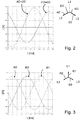
- Fig. 3 the load on the phase conductors L1, L2, L3 at connection point 6 of the charging infrastructure arrangement is shown. It can be seen here that the load currents i61, i62, i63 in the phase conductors L1, L2, L3 are of the same size and are out of phase.
- the unbalanced load compensation unit 5 reproduces the in the graph Fig. 4 compensating currents i51, i52, i53 shown. In practical terms, this means that the phase with the least load (phase conductor L1) draws energy and transfers this energy to the highest loaded phases (phase conductor L2, L3) is distributed.
- the powers p51, p52, p53 fed in or shifted by means of the power electronics of the unbalanced load compensation unit 5 are shown in the graph according to FIG Fig. 5 for the various phase conductors L1, L2, L3 or the connecting conductors 16, 17, 18 assigned to them.
- FIGS Figures 6 to 8 Three alternative embodiments of the power electronics bridge circuit 20 are shown in FIGS Figures 6 to 8 reproduced.
- the bridge circuit 20 provides a bridge branch 10, 11, 12 for the connection conductors 16, 17, 18 assigned to the phase conductors L1, L2, L3 and a further bridge branch 13 for the connection conductor 19 of the unbalanced load compensation unit 5 assigned to the neutral conductor N. Furthermore, an intermediate circuit 14 with an intermediate circuit capacitor is included.
- the connection conductors 16, 17, 18, 19 are each connected to the phase conductors L1, L2, L3 and the neutral conductor N of the three-phase supply system 7 via an inductance or a coil.
- the bridge circuit 20 comprises the bridge branches 10, 11, 12 for the connection conductors 16, 17, 18 assigned to the phase conductors L1, L2, L3, cf. Fig. 7 .
- the connection conductors 16, 17, 18 assigned to the phase conductors L1, L2, L3 are each connected to the phase conductors L1, L2, L3 of the three-phase supply system 7 via an inductance or a coil.
- the connection conductor 19 assigned to the neutral conductor N is connected to a midpoint of the intermediate circuit capacitance of the intermediate circuit 14 between two series-connected capacitors or capacities of preferably the same size.
- a third alternative embodiment of the bridge circuit according to Fig. 8 corresponds essentially to the embodiment according to Fig. 7 .
- the connection conductor 19 assigned to the neutral conductor N is also connected to the neutral conductor N of the three-phase supply system 7 via an inductance or a coil.
- the bridge branches 10, 11, 12, 13 are each assigned switching means 15 for clocked operation of the connection conductors 16, 17, 18, 19.
- Find 15 as switching means Use of power semiconductors, for example MOSFETs, IGBTs, thyristors, IGCTs or GTOs.
- the switching means 15 are actuated or controlled via the control of the unbalanced load compensation unit 5.
- the unbalanced load compensation unit 5 can be implemented as an independent physical component and connected to the three-phase supply line system 7.
- the unbalanced load compensation unit 5 and a single AC charging point can be implemented in an integrated manner.
- a plurality of unbalanced load compensation units 5 can be provided. These can be implemented, for example, integrated into the various AC charging points of the charging infrastructure arrangement, with the result that the equalization currents are applied in a distributed manner.
- the charging infrastructure arrangement can provide charging stations with more than one AC charging point.
- the charging infrastructure arrangement according to the invention can be designed in the sense of a supply infrastructure arrangement to use electric vehicles connected to the charging infrastructure arrangement as an energy source as part of a higher-level energy management system and to feed energy stored in the vehicles into the supply network as required. This can be useful, for example, to temporarily compensate for peak loads.
- the charging infrastructure arrangement according to the invention comprises at least one AC charging point 1, 2, 3, 4, further AC loads can also be connected to the three-phase supply system 7 and load it symmetrically or asymmetrically.
- the charging infrastructure arrangement according to the invention can comprise a DC charging device.
- the unbalanced load compensation unit 5 can be part of the DC charging device.
- the load on the three-phase supply system 7 is also determined as an example, cumulatively via the measured load currents of each phase conductor L1, L2, L3, which are determined by the sum of the load or charging currents i13, i22, i33, i42 of the AC charging points 1, 2, 3, 4 is defined.
- the load could be via the cumulative power or locally via the Load or charging currents i13, i22, i33, i42 or the local apparent power of the individual AC charging points 1, 2, 3, 4 can be determined.
Landscapes
- Engineering & Computer Science (AREA)
- Power Engineering (AREA)
- Transportation (AREA)
- Mechanical Engineering (AREA)
- Supply And Distribution Of Alternating Current (AREA)
- Charge And Discharge Circuits For Batteries Or The Like (AREA)
Applications Claiming Priority (1)
| Application Number | Priority Date | Filing Date | Title |
|---|---|---|---|
| DE102019135654.7A DE102019135654A1 (de) | 2019-12-23 | 2019-12-23 | Ladeinfrastrukturanordnung zum Laden von Elektrofahrzeugen und Betriebsverfahren hierfür |
Publications (1)
| Publication Number | Publication Date |
|---|---|
| EP3843230A1 true EP3843230A1 (fr) | 2021-06-30 |
Family
ID=73856048
Family Applications (1)
| Application Number | Title | Priority Date | Filing Date |
|---|---|---|---|
| EP20215866.3A Pending EP3843230A1 (fr) | 2019-12-23 | 2020-12-21 | Agencement d'infrastructure de charge destiné à la charge des véhicules électriques et procédé de fonctionnement associé |
Country Status (2)
| Country | Link |
|---|---|
| EP (1) | EP3843230A1 (fr) |
| DE (1) | DE102019135654A1 (fr) |
Cited By (2)
| Publication number | Priority date | Publication date | Assignee | Title |
|---|---|---|---|---|
| EP4391272A1 (fr) * | 2022-12-23 | 2024-06-26 | Mitteldeutsche Netzgesellschaft Strom mbH | Procédé de gestion d'énergie lors de la fourniture d'énergie électrique, produit programme informatique, système et véhicule |
| WO2024180187A1 (fr) * | 2023-03-02 | 2024-09-06 | Brusa Elektronik Ag | Convertisseur multiphase et procédé de compensation de charges de phase |
Families Citing this family (1)
| Publication number | Priority date | Publication date | Assignee | Title |
|---|---|---|---|---|
| DE102023113578A1 (de) * | 2023-05-24 | 2024-11-28 | Bayerische Motoren Werke Aktiengesellschaft | Gleichzeitiges Laden und Entladen einer Fahrbatterie eines Elektrofahrzeuges |
Citations (3)
| Publication number | Priority date | Publication date | Assignee | Title |
|---|---|---|---|---|
| WO2012128626A2 (fr) * | 2011-03-22 | 2012-09-27 | Abb B.V. | Système pour la charge de la batterie d'au moins un véhicule électrique, chargeur et procédé |
| CN106314172A (zh) * | 2016-08-31 | 2017-01-11 | 苏州迈力电器有限公司 | 一种基于三相负荷不平衡自动调节的交流充电桩 |
| WO2019129729A1 (fr) * | 2017-12-31 | 2019-07-04 | Vito Nv | Compensation de déséquilibre par redistribution optimale du courant |
Family Cites Families (4)
| Publication number | Priority date | Publication date | Assignee | Title |
|---|---|---|---|---|
| JP4893486B2 (ja) * | 2007-06-12 | 2012-03-07 | 日産自動車株式会社 | 電力補償システム |
| DE102010024138A1 (de) * | 2010-06-17 | 2011-12-22 | Siemens Aktiengesellschaft | Vorrichtung zur Netzspannungssymmetrisierung |
| FR2993514B1 (fr) * | 2012-07-20 | 2015-12-04 | Schneider Electric Ind Sas | Procede et dispositif de distribution d'energie electrique |
| DE102019105661A1 (de) * | 2019-03-06 | 2020-09-10 | Wobben Properties Gmbh | Ladestation zum Laden von Elektrofahrzeugen |
-
2019
- 2019-12-23 DE DE102019135654.7A patent/DE102019135654A1/de active Pending
-
2020
- 2020-12-21 EP EP20215866.3A patent/EP3843230A1/fr active Pending
Patent Citations (3)
| Publication number | Priority date | Publication date | Assignee | Title |
|---|---|---|---|---|
| WO2012128626A2 (fr) * | 2011-03-22 | 2012-09-27 | Abb B.V. | Système pour la charge de la batterie d'au moins un véhicule électrique, chargeur et procédé |
| CN106314172A (zh) * | 2016-08-31 | 2017-01-11 | 苏州迈力电器有限公司 | 一种基于三相负荷不平衡自动调节的交流充电桩 |
| WO2019129729A1 (fr) * | 2017-12-31 | 2019-07-04 | Vito Nv | Compensation de déséquilibre par redistribution optimale du courant |
Non-Patent Citations (2)
| Title |
|---|
| "Power Electronics Handbook : Devices, Circuits and Applications", 31 December 2006, article WATANABE E H ET AL: "Flexible AC Transmission Systems", pages: 797 - 822, XP093025326 * |
| LAM CHI-SENG ET AL: "Review of current quality compensators for high power unidirectional electric vehicle battery charger", 2013 1ST INTERNATIONAL FUTURE ENERGY ELECTRONICS CONFERENCE (IFEEC), IEEE, 19 December 2013 (2013-12-19), pages 259 - 264, XP032531772, DOI: 10.1109/IFEEC.2013.6687513 * |
Cited By (2)
| Publication number | Priority date | Publication date | Assignee | Title |
|---|---|---|---|---|
| EP4391272A1 (fr) * | 2022-12-23 | 2024-06-26 | Mitteldeutsche Netzgesellschaft Strom mbH | Procédé de gestion d'énergie lors de la fourniture d'énergie électrique, produit programme informatique, système et véhicule |
| WO2024180187A1 (fr) * | 2023-03-02 | 2024-09-06 | Brusa Elektronik Ag | Convertisseur multiphase et procédé de compensation de charges de phase |
Also Published As
| Publication number | Publication date |
|---|---|
| DE102019135654A1 (de) | 2021-06-24 |
Similar Documents
| Publication | Publication Date | Title |
|---|---|---|
| DE69017884T2 (de) | Vorrichtung zur Steuerung des Blindwiderstands einer Starkstromleitung. | |
| DE102008034109B4 (de) | Schaltung zur Nachbildung einer elektrischen Last | |
| EP1759450B1 (fr) | Circuit commutateur polyphase pauvre en oscillations harmoniques | |
| EP2608399B1 (fr) | Procédé de détection de défaut de terre pendant l'opération d'un convertisseur | |
| EP3843230A1 (fr) | Agencement d'infrastructure de charge destiné à la charge des véhicules électriques et procédé de fonctionnement associé | |
| EP3270501A1 (fr) | Dispositif de transmission d'énergie électrique avec une liaison à haute tension continue | |
| EP3132515B1 (fr) | Onduleur pour délivrer de la puissance réactive et procédé de régulation de celui-ci | |
| DE3608704A1 (de) | Spannungsspitzen freier festkoerperschalter und einrichtung zur automatischen leistungsfaktor-korrektur | |
| EP2619839A1 (fr) | Procédé de réglage de la tension d'un circuit intermédiaire de tension continue | |
| EP3544145A1 (fr) | Procédé de charge des consommateurs électriques | |
| DE3429116C2 (fr) | ||
| EP2700154B1 (fr) | Convertisseurs de matrices et procédé pour produire une tension alternative dans un second réseau de tension alternative à partir d'une première tension alternative dans un premier réseau de tension alternative au moyen d'un convertisseur de matrices | |
| EP3842278A1 (fr) | Agencement d'infrastructure de charge destiné à la charge des véhicules électriques et procédé de fonctionnement associé | |
| AT512488A1 (de) | Gleichrichterschaltung mit drossel | |
| DE112022002486T5 (de) | Einstellung der umrichterklemmenspannung in leistungssystem | |
| WO2015169692A2 (fr) | Installation et procédé pour fournir une puissance réactive | |
| DE102018216233A1 (de) | Ladeschaltung für einen fahrzeugseitigen elektrischen Energiespeicher | |
| EP3138176B1 (fr) | Convertisseur servant à la compensation symétrique d'énergie réactive et procédé permettant le réglage dudit convertisseur | |
| WO2018113926A1 (fr) | Convertisseur | |
| WO1994014220A1 (fr) | Procede et dispositif de determination des nombres ordinaux de courants d'harmoniques non caracteristiques et de compensation de ceux-ci | |
| EP3783630A1 (fr) | Dispositif de suppression d'une composante courant continu lors du fonctionnement d'un appareil électrique connecté à un réseau haute tension | |
| DE102014100158B4 (de) | Zuschaltverfahren | |
| DE102018116303A1 (de) | Blindleistungskompensation für Stromschienen | |
| DE102018209139A1 (de) | Wechselspannungs-Ladevorrichtung | |
| EP3867987B1 (fr) | Fonctionnement d'un convertisseur multiniveau |
Legal Events
| Date | Code | Title | Description |
|---|---|---|---|
| PUAI | Public reference made under article 153(3) epc to a published international application that has entered the european phase |
Free format text: ORIGINAL CODE: 0009012 |
|
| STAA | Information on the status of an ep patent application or granted ep patent |
Free format text: STATUS: THE APPLICATION HAS BEEN PUBLISHED |
|
| AK | Designated contracting states |
Kind code of ref document: A1 Designated state(s): AL AT BE BG CH CY CZ DE DK EE ES FI FR GB GR HR HU IE IS IT LI LT LU LV MC MK MT NL NO PL PT RO RS SE SI SK SM TR |
|
| STAA | Information on the status of an ep patent application or granted ep patent |
Free format text: STATUS: REQUEST FOR EXAMINATION WAS MADE |
|
| 17P | Request for examination filed |
Effective date: 20211012 |
|
| RBV | Designated contracting states (corrected) |
Designated state(s): AL AT BE BG CH CY CZ DE DK EE ES FI FR GB GR HR HU IE IS IT LI LT LU LV MC MK MT NL NO PL PT RO RS SE SI SK SM TR |
|
| STAA | Information on the status of an ep patent application or granted ep patent |
Free format text: STATUS: EXAMINATION IS IN PROGRESS |
|
| 17Q | First examination report despatched |
Effective date: 20230224 |
|
| RAP1 | Party data changed (applicant data changed or rights of an application transferred) |
Owner name: COMPLEO CHARGING SOLUTIONS GMBH & CO. KG |