EP3843348A1 - Signalübertragungsverfahren und -vorrichtung sowie computerspeichermedium - Google Patents
Signalübertragungsverfahren und -vorrichtung sowie computerspeichermedium Download PDFInfo
- Publication number
- EP3843348A1 EP3843348A1 EP18934022.7A EP18934022A EP3843348A1 EP 3843348 A1 EP3843348 A1 EP 3843348A1 EP 18934022 A EP18934022 A EP 18934022A EP 3843348 A1 EP3843348 A1 EP 3843348A1
- Authority
- EP
- European Patent Office
- Prior art keywords
- ssb
- transmission time
- scs
- transmission
- network device
- Prior art date
- Legal status (The legal status is an assumption and is not a legal conclusion. Google has not performed a legal analysis and makes no representation as to the accuracy of the status listed.)
- Ceased
Links
- 238000000034 method Methods 0.000 title claims abstract description 61
- 230000008054 signal transmission Effects 0.000 title claims abstract description 25
- 230000005540 biological transmission Effects 0.000 claims abstract description 249
- 238000004891 communication Methods 0.000 claims description 46
- 238000005259 measurement Methods 0.000 claims description 43
- 230000015654 memory Effects 0.000 claims description 27
- 238000012545 processing Methods 0.000 claims description 24
- 238000004590 computer program Methods 0.000 claims description 14
- 238000001228 spectrum Methods 0.000 description 27
- 238000010586 diagram Methods 0.000 description 15
- 238000009826 distribution Methods 0.000 description 7
- 239000000203 mixture Substances 0.000 description 7
- 238000005516 engineering process Methods 0.000 description 6
- 230000006870 function Effects 0.000 description 6
- 235000019527 sweetened beverage Nutrition 0.000 description 4
- 238000011161 development Methods 0.000 description 2
- 238000010295 mobile communication Methods 0.000 description 2
- 230000001105 regulatory effect Effects 0.000 description 2
- 238000004220 aggregation Methods 0.000 description 1
- 230000002776 aggregation Effects 0.000 description 1
- 235000019800 disodium phosphate Nutrition 0.000 description 1
- 230000009977 dual effect Effects 0.000 description 1
- 230000002349 favourable effect Effects 0.000 description 1
- 239000011521 glass Substances 0.000 description 1
- 230000000977 initiatory effect Effects 0.000 description 1
- 230000007774 longterm Effects 0.000 description 1
- 230000003287 optical effect Effects 0.000 description 1
- 238000004549 pulsed laser deposition Methods 0.000 description 1
- 230000011664 signaling Effects 0.000 description 1
- 230000003068 static effect Effects 0.000 description 1
- 230000001360 synchronised effect Effects 0.000 description 1
Images
Classifications
-
- H—ELECTRICITY
- H04—ELECTRIC COMMUNICATION TECHNIQUE
- H04L—TRANSMISSION OF DIGITAL INFORMATION, e.g. TELEGRAPHIC COMMUNICATION
- H04L27/00—Modulated-carrier systems
- H04L27/26—Systems using multi-frequency codes
- H04L27/2601—Multicarrier modulation systems
- H04L27/2602—Signal structure
-
- H—ELECTRICITY
- H04—ELECTRIC COMMUNICATION TECHNIQUE
- H04L—TRANSMISSION OF DIGITAL INFORMATION, e.g. TELEGRAPHIC COMMUNICATION
- H04L27/00—Modulated-carrier systems
- H04L27/26—Systems using multi-frequency codes
- H04L27/2601—Multicarrier modulation systems
- H04L27/2647—Arrangements specific to the receiver only
- H04L27/2655—Synchronisation arrangements
-
- H—ELECTRICITY
- H04—ELECTRIC COMMUNICATION TECHNIQUE
- H04L—TRANSMISSION OF DIGITAL INFORMATION, e.g. TELEGRAPHIC COMMUNICATION
- H04L27/00—Modulated-carrier systems
- H04L27/26—Systems using multi-frequency codes
- H04L27/2601—Multicarrier modulation systems
- H04L27/2602—Signal structure
- H04L27/26025—Numerology, i.e. varying one or more of symbol duration, subcarrier spacing, Fourier transform size, sampling rate or down-clocking
-
- H—ELECTRICITY
- H04—ELECTRIC COMMUNICATION TECHNIQUE
- H04L—TRANSMISSION OF DIGITAL INFORMATION, e.g. TELEGRAPHIC COMMUNICATION
- H04L27/00—Modulated-carrier systems
- H04L27/26—Systems using multi-frequency codes
- H04L27/2601—Multicarrier modulation systems
- H04L27/2602—Signal structure
- H04L27/261—Details of reference signals
-
- H—ELECTRICITY
- H04—ELECTRIC COMMUNICATION TECHNIQUE
- H04L—TRANSMISSION OF DIGITAL INFORMATION, e.g. TELEGRAPHIC COMMUNICATION
- H04L5/00—Arrangements affording multiple use of the transmission path
- H04L5/003—Arrangements for allocating sub-channels of the transmission path
- H04L5/0048—Allocation of pilot signals, i.e. of signals known to the receiver
- H04L5/005—Allocation of pilot signals, i.e. of signals known to the receiver of common pilots, i.e. pilots destined for multiple users or terminals
-
- H—ELECTRICITY
- H04—ELECTRIC COMMUNICATION TECHNIQUE
- H04W—WIRELESS COMMUNICATION NETWORKS
- H04W56/00—Synchronisation arrangements
- H04W56/001—Synchronization between nodes
-
- H—ELECTRICITY
- H04—ELECTRIC COMMUNICATION TECHNIQUE
- H04W—WIRELESS COMMUNICATION NETWORKS
- H04W56/00—Synchronisation arrangements
- H04W56/0055—Synchronisation arrangements determining timing error of reception due to propagation delay
- H04W56/0065—Synchronisation arrangements determining timing error of reception due to propagation delay using measurement of signal travel time
-
- H—ELECTRICITY
- H04—ELECTRIC COMMUNICATION TECHNIQUE
- H04W—WIRELESS COMMUNICATION NETWORKS
- H04W72/00—Local resource management
- H04W72/04—Wireless resource allocation
- H04W72/044—Wireless resource allocation based on the type of the allocated resource
- H04W72/0446—Resources in time domain, e.g. slots or frames
-
- H—ELECTRICITY
- H04—ELECTRIC COMMUNICATION TECHNIQUE
- H04W—WIRELESS COMMUNICATION NETWORKS
- H04W72/00—Local resource management
- H04W72/04—Wireless resource allocation
- H04W72/044—Wireless resource allocation based on the type of the allocated resource
- H04W72/0453—Resources in frequency domain, e.g. a carrier in FDMA
Definitions
- Embodiments of the disclosure relate to the technical field of mobile communication, and particularly to a method and apparatus for signal transmission and a computer storage medium.
- Unlicensed spectrums are spectrums divided by countries and districts and available for radio device communication.
- the spectrums may usually be considered as shared spectrums, namely communication devices in different communication systems can use the spectrums without applying to the governments for dedicated spectrum grants when meeting regulatory requirements of the countries or the districts on the spectrums.
- Transmission opportunities of SSB can be increased as much as possible to ensure successful transmission of the SSB.
- increase of the transmission opportunities may be determined according to a length of a time window, a Subcarrier Spacing (SCS) of the SSB and the amount of the SSB, so that the impact on measurement of a terminal can also be reduced.
- SCS Subcarrier Spacing
- the embodiments of the disclosure provide a signal transmission method, which may be implemented by a terminal device and include that:
- the embodiments of the disclosure provide a signal transmission method, which may be implemented by a network device and include that:
- the embodiments of the disclosure provide a terminal device, which may include a first processing unit and a first communication unit.
- the first processing unit may be configured to determine a transmission time set of SSB, the transmission time set being determined according to at least one of a length of a time window, an SCS of the SSB and the amount of the SSB.
- the first communication unit may be configured to receive the SSB from a network device based on the transmission time set.
- the embodiments of the disclosure provide a network device, which may include a second processing unit and a second communication unit.
- the second processing unit may be configured to determine a transmission time set of SSB, the transmission time set being determined according to at least one of a length of a time window, an SCS of the SSB and the amount of the SSB.
- the second communication unit may be configured to send the SSB to a terminal device based on the transmission time set.
- the embodiments of the disclosure provide a terminal device, which may include a first memory and a first processor.
- the first memory may be configured to store a computer program capable of running in the first processor.
- the first processor may be configured to run the computer program to implement the operations of the method of the first aspect.
- the embodiments of the disclosure provide a network device, which may include a second memory and a second processor.
- the second memory may be configured to store a computer program capable of running in the second processor.
- the second processor may be configured to run the computer program to implement the operations of the method of the second aspect.
- the embodiments of the disclosure provide a computer storage medium, which may store a signal transmission program, the signal transmission program being executed by at least one processor to implement the operations of the method of the first aspect or the second aspect.
- the embodiments of the disclosure provide the signal transmission method and apparatus and the computer storage medium.
- the method implemented by the terminal device includes that: a transmission time set of the SSB is determined, the transmission time set being determined according to at least one of: the length of a time window, the SCS of SSB and the amount of the SSB; and the SSB transmitted by the network device is received based on the transmission time set.
- Transmission opportunities of SSB can be increased as much as possible to ensure successful transmission of the SSB.
- increase of the transmission opportunities may be determined according to the length of a time window, the SCS of SSB and the amount of the SSB, so that the impact on measurement of a terminal can also be reduced.
- GSM Global System of Mobile communication
- CDMA Code Division Multiple Access
- WCDMA Wideband Code Division Multiple Access
- GPRS General Packet Radio Service
- UMTS Universal Mobile Telecommunication System
- LTE Long Term Evolution
- LTE-A Advanced LTE
- NR-U Universal Terred spectrum
- D2D Device to Device
- M2M Machine to Machine
- MTC Machine Type Communication
- V2V Vehicle to Vehicle
- the above-mentioned communication system may be applied to a licensed spectrum or may also be applied to an unlicensed spectrum, for example, a 2.4GHz, 5GHz, 37GHz or 60GHz spectrum.
- CA Carrier Aggregation
- DC Dual Connectivity
- SA Standalone
- the CA network deployment scenario may be that a primary carrier is in a licensed spectrum, a secondary carrier is in an unlicensed spectrum and the primary carrier is connected with the secondary carrier through an ideal backhaul.
- the DC network deployment scenario may be that a primary carrier is in a licensed spectrum, a secondary carrier is in an unlicensed spectrum and the primary carrier is connected with the secondary carrier through a non-ideal backhaul.
- a system on the primary carrier and a system on the secondary carrier may be different systems, for example, the system on the primary carrier is an LTE system, and the system on the secondary carrier is an NR system.
- the system on the primary carrier and the system on the secondary carrier may also be the same system, for example, both the systems on the primary carrier and the secondary carrier are LTE systems or NR systems.
- a terminal device may access a network through a system on the unlicensed spectrum.
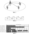
- the communication system may include terminal devices 10, 12 and 14 and a network device 20, and the terminal devices are communicated with the network device through radio links respectively, as shown by the double sided arrows.
- the terminal devices 10, 12 and 14 may also be called User Equipment (UE), an access terminal, a user unit, a user Station (ST), a mobile radio ST, a mobile ST, a remote ST, a remote terminal, a mobile device, a user terminal, a terminal, a wireless communication device, a user agent or a user device.
- UE User Equipment
- ST user Station
- ST mobile radio ST
- ST mobile ST
- remote ST remote terminal
- mobile device a user terminal
- a wireless communication device a user agent or a user device.
- the terminal device may be an ST in a Wireless Local Area Network (WLAN), and may be a cell phone, a cordless phone, a Session Initiation Protocol (SIP) phone, a Wireless Local Loop (WLL) ST, a Personal Digital Assistant (PDA), a handheld device with a wireless communication function, a computing device, another processing device connected to a wireless modem, a vehicle device, a wearable device, a terminal device in a next-generation communication system, for example, a future 5G network, a terminal device in a future evolved Public Land Mobile Network (PLMN) or the like.
- the terminals device may also be wearable devices.
- the wearable device may also be called a wearable intelligent device and is a generic term of wearable devices obtained by performing intelligent designing and development on daily wearing products, for example, glasses, gloves, watches, clothes and shoes.
- the network device 20 may be a device configured to communicate with the terminal devices, and the network device may be an Access Point (AP) in the WLAN, a Base Transceiver Station (BTS) in a GSM or CDMA, or may also be a NodeB (NB) in WCDMA, or may be an Evolutional Node B (eNB or eNodeB) in LTE, or a relay station or AP, or a vehicle device, a wearable device, a network device such as a 5G base ST (gNB) in an NR network, a network device in the future evolved PLMN or the like.
- AP Access Point
- BTS Base Transceiver Station
- NB NodeB
- eNB Evolutional Node B
- gNB 5G base ST
- gNB 5G base ST
- the network device 20 may provide service for a cell, and the terminal devices 10, 12 and 14 can communicate with the network device 20 through a transmission resource (for example, a frequency-domain resource or a spectrum resource) for the cell.
- the cell may be a cell corresponding to the network device 20 (for example, a base ST), and the cell may belong to a macro base ST or may belong to a base ST corresponding to a small cell.
- the small cell may include: a metro cell, a micro cell, a pico cell, a femto cell and the like. These small cells have the characteristics of small coverage and low transmitted power and are applied to provision of high-rate data transmission service.
- multiple cells can simultaneously work on the same frequency in a carrier in an LTE system or an NR system.
- concepts of carrier and cell may also be considered to be equivalent.
- a CA scenario when a secondary carrier is configured for UE, both a carrier index of the secondary carrier and a cell Identity (ID) of a secondary cell working on the secondary carrier can be contained.
- ID cell Identity
- the concepts of carrier and cell may be considered to be equivalent.
- access to a carrier and access to a cell are equivalent.
- a shared channel and signal in an NR system for example, a Synchronization Signal (SS) and a Physical Broadcast Channel (PBCH)
- SS Synchronization Signal
- PBCH Physical Broadcast Channel
- Multi-beam transmission of a SS may be implemented by defining an SS/PBCH burst set.
- An SS/PBCH burst set may include one or more SS/PBCH blocks, and an SS/PBCH block is configured to bear an SS and PBCH of a beam.
- an SS/PBCH burst set may include SSs of N beams corresponding to SS/PBCH blocks in a cell.
- the maximum number L of the SS/PBCH blocks is related to a band of the system. For example, when the band of the system does not exceed 3GHz, the maximum number L of the SS/PBCH blocks is valued to be 4; when the band of the system ranges from 3GHz to 6GHz, the maximum number L of the SS/PBCH blocks is valued to be 8; and when the band of the system ranges from 6GHz to 52.6GHz, the maximum number L of the SS/PBCH blocks is valued to be 64.
- SSB includes a Primary Synchronization Signal (PSS) 201, a Secondary Synchronization Signal (SSS) 202 and two New Radio Access Technology-based Physical Broadcast Channels (NR-PBCHs), the two NR-PBCHs being PBCH 203 and PBCH 204 respectively.
- PSS Primary Synchronization Signal
- SSS Secondary Synchronization Signal
- NR-PBCHs New Radio Access Technology-based Physical Broadcast Channels
- all SSBs may be transmitted in a 5ms time window, and may be repeatedly transmitted according to a certain period. The period may be configured through an upper-layer parameter SSB-timing, including 5ms, 10ms, 20ms, 40ms, 80ms and 160ms, etc. No specific limits are made in the embodiment of the disclosure.
- FIG. 3 a slot distribution diagram of SSB according to an embodiment of the disclosure is shown.
- FIG. 3 includes six slot distributions corresponding to different SCSs and different SSB numbers L.
- a slot includes 14 symbols and may bear two SSBs. That is, in a 5ms time window shown in FIG. 3 , four SSBs are distributed in first two slots.
- a communication device follows a Listen-Before-Talk (LBT) principle, namely a communication device, before transmitting a signal in a channel of an unlicensed spectrum, is required to listen the channel first.
- LBT Listen-Before-Talk
- the communication device can send a signal only when a channel listening result is that the channel is idle.
- the communication device cannot send the signal.
- a time length for signal transmission of the communication device using the channel of the unlicensed spectrum cannot exceed Maximum Channel Occupation Time (MCOT).
- MCOT Maximum Channel Occupation Time
- SSB cannot be successfully transmitted at SSB transmission time defined in present NR in SSB transmitting process due to the probability of an LBT failure.
- An existing solution is to increase transmission opportunities of SSB and define new SSB transmission time as an alternative. In such a manner, when the SSB cannot be transmitted at certain transmission time due to LBT failure, the SSB can be transmitted at alternative transmission time.
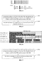
- FIG. 4 a schematic diagram of increasing transmission opportunities according to an embodiment of the disclosure.
- LBT executed before transmission time of SSB index 0 fails, channel listening is needed to be continued.
- LBT executed before SSB index 2 succeeds, residual SSBs may be started to be transmitted from the SSB index 2.
- the SSB index 0 and SSB index 1 that are not successfully transmitted before may be transmitted.
- Practical transmission time of the SSB index 0 and the SSB index 1 may be alternative transmission time.
- practical transmission time of SSB may be target transmission time (for example, predefined transmission time) or may also be alternative transmission time.
- a length of a transmission window of the SSB may also be increased at the same time of increasing the transmission opportunities of the SSB.
- a terminal device measures SSB according to a preconfigured window (for example, SSB Measurement Timing Configuration (SMTC) window)
- SMTC SSB Measurement Timing Configuration
- a length of a transmission window of the SSB is increased, for measuring transmitting positions of the SSB, a relatively large SMTC window is needed to be configured, which may bring negative impact to measurement of the terminal, for example, power conservation and a transmission interruption time length of inter-frequency measurement.
- the method may be implemented by a terminal device in the abovementioned communication system.
- the method may include the following operations.
- a transmission time set of SSB is determined, the transmission time set being determined according to at least one of: a length of a time window, an SCS of the SSB and the amount of the SSB.
- the SSB transmitted by a network device is received based on the transmission time set.
- a transmission time set of SSB may be determined, the transmission time set being determined according to at least one of: a length of a time window, an SCS of the SSB and the amount of the SSB.
- the SSB transmitted by the network device may be received based on the transmission time set. Since the impact of parameters such as the length of a time window, an SCS of the SSB and the amount of the SSB is also considered when a transmission opportunity of the SSB is determined, transmission opportunities of the SSB can be increased as much as possible, and meanwhile, impact on measurement of the terminal can also be reduced.
- a transmission time set of SSB may be determined according to parameter information such as a length of a time window, an SCS of the SSB and the amount of the SSB.
- the transmission time set represents all possible transmission time at which the SSB can be transmitted. Therefore, for the technical solution shown in FIG. 5 , in a possible implementation mode, the transmission time set may include at least one first transmission time and a second transmission time.
- the second transmission time represents target transmission time.
- the at least one first transmission time represents alternative transmission time other than the second transmission time.
- the operation that the transmission time set of the SSB is determined may specifically include that:
- the at least one first transmission time within the time window is acquired according to the SCS of the SSB and the amount of the SSB;
- the transmission time set of the SSB is determined according to the at least one first transmission time.
- first transmission time there may be multiple pieces of first transmission time, which are obtained based on transmission opportunities additionally increased for the terminal device. For ensuring that SSB can be successfully transmitted, more transmission opportunities need to be obtained as much as possible, for example, acquiring a maximum amount of first transmission time.
- the transmission time may also be called alternative transmission time.
- second transmission time There is only one piece of second transmission time, which is obtained according to transmission time predefined for the terminal device.
- the second transmission time may also be called the target transmission time.
- the terminal device may receive the SSB from the network device.
- practical transmission time of the SSB may be the target transmission time or may also be one or more pieces of alternative transmission time. Specifically, the practical transmission time of the SSB may be obtained by the network device according to a practical condition of channel listening and channel preemption. No specific limits are made thereto in the embodiment of the disclosure.
- the slot distribution of SSB shown in FIG. 3 is taken as an example. Under different SCSs and L values, slot distributions of the SSB in a 5ms time window are different. There is made such a hypothesis that the time window (for example, an SMTC window) is set to be 5ms, and in this SMTC window, transmission opportunities of the SSB need to be increased. The transmission opportunities, obtained according to different parameter information such as different sizes of the SMTC window, SCSs and L, of the SSB are different. The transmission time corresponding to all these possible transmission opportunities of the SSB forms a transmission time set.
- the time window for example, an SMTC window
- SCSs and L transmission opportunities of the SSB
- the time window (for example, a SMTC window) is still set to be, for example, 5ms.
- transmission opportunities determined for the SSB are different.
- Transmission time corresponding to the grey filled pattern is predefined transmission time, i.e., the second transmission time.
- Transmission time corresponding to other filled patterns than the grey filled pattern is alternative transmission time, i.e., the first transmission time.
- all the other filled patterns are adopted to represent the transmission opportunities increased for the SSB.
- the time window may be a predefined time window or a measurement time window configured by the network device.
- the method may specifically further include that:
- the time window may be the predefined window or may also be the measurement time window configured by the network device.
- the length of the time window may specifically be set to be, for example, 5ms, 8ms or 10ms according to a practical requirement. No specific limits are made thereto in the embodiment of the disclosure.
- the length of the time window is 5ms, i.e., a time length of a half frame.
- all the transmission opportunities increased for the SSB are within the 5ms time window and no larger time window is configured, so that signal measurement of the terminal device over the SSB can still be implemented within the 5ms time window, and negative impact on measurement of the terminal is avoided.
- the amount of the SSB may be a predefined amount of the SSB or an amount of the SSB that is actually transmitted.
- the maximum amount of the SSB is related to a band of a system.
- the maximum number L of SS/PBCH blocks is valued to be 4.
- the maximum number L of the SS/PBCH blocks is valued to be 8.
- the maximum number L of the SS/PBCH blocks is valued to be 64.
- the amount of the SSB may be the predefined amount of the SSB or may also be the amount of the SSB that is actually transmitted. No specific limits are made thereto in the embodiment of the disclosure. FIG. 6 is still taken as an example. In FIG.
- a value of the amount L of the SSB may be 4, or may also be 8 or may also be 64.
- transmission opportunities correspondingly increased for the SSB under different parameter information such as different L and SCSs are shown in FIG. 6 .
- the SCS of the SSB may be a predefined SCS or an SCS configured by the network device.
- an SCS of the SSB there is usually one or more configurations for an SCS of the SSB, for example, 15kHz, 30kHz, 120kHz and 240kHz.
- the SCS may be predefined or may also be configured by a network device.
- the SCS may also be indicated by the network device through signaling, or may even be determined according to an SCS of a physical random access channel. No specific limits are made thereto in the embodiment of the disclosure.
- the length of the time window is still 5ms.
- the transmission opportunities of the SSB can be increased as much as possible, and meanwhile, the impact on the measurement of the terminal can also be reduced.
- the embodiment provides the signal transmission method.
- a transmission time set of SSB can be determined, the transmission time set being determined according to at least one of: a length of a time window, a SCS of the SSB and the amount of the SSB.
- the SSB transmitted by a network device can be received based on the transmission time set. Therefore, the transmission opportunities of the SSB can be increased as much as possible, and meanwhile, the impact on measurement of the terminal can also be reduced.
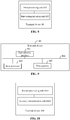
- FIG. 7 a flow of another signal transmission method provided in the embodiment of the disclosure is shown.
- the method may be implemented by the network device shown in FIG. 1 .
- the method may include the following operations.
- a transmission time set of SSB is determined, the transmission time set being determined according to at least one of: a length of a time window, an SCS of the SSB and the amount of the SSB.
- the SSB is transmitted to a terminal device according to the transmission time set.
- a transmission time set of SSB can be determined, the transmission time set being determined according to at least one of: a length of a time window, a SCS of the SSB and the amount of the SSB, and the SSB can be transmitted to the terminal device according to the transmission time set. Since impact of parameters such as the length of the time window, the SCS of the SSB and the amount of the SSB is also considered when a transmission opportunity of the SSB is determined, transmission opportunities of the SSB can be increased as much as possible, and meanwhile, impact on measurement of the terminal can also be reduced.
- the transmission time set may include at least one first transmission time and a second transmission time.
- the second transmission time represents target transmission time
- the at least one first transmission time represents alternative transmission time other than the second transmission time.
- the operation that the transmission time set of the SSB is determined may specifically include that:
- the network device may send the SSB to the terminal device by channel listening or channel preemption.
- Practical transmission time of the SSB may be obtained by the network device according to a practical condition of channel listening and channel preemption.
- the practical transmission time may be the target transmission time or may also be one or more pieces of alternative transmission time. No specific limits are made thereto in the embodiment of the disclosure.
- the time window may be a predefined time window or a measurement time window configured by the network device.
- the method may specifically further include that: when the time window is the measurement time window, a signal measurement result of the SSB is received from the terminal device.
- the time window may be the predefined window or may also be the measurement time window configured by the network device. No specific limits are made in the embodiment of the disclosure. There is made such a hypothesis that, when the time window is the measurement time window, the terminal device may perform signal measurement on the SSB and the network device may receive the signal measurement result from the terminal device.
- the embodiment provides the signal transmission method.
- a transmission time set of SSB can be determined, the transmission time set being determined according to at least one of: a length of a time window, a SCS of the SSB and the amount of the SSB.
- the SSB can be transmitted to the terminal device based on the transmission time set. Therefore, the transmission opportunities of the SSB can be increased as much as possible, and meanwhile, the impact on measurement of the terminal can also be reduced.
- the terminal device 80 includes a first processing unit 801 and a first communication unit 802.
- the first processing unit 801 is configured to determine a transmission time set of SSB, the transmission time set being determined according to at least one of: a length of a time window, an SCS of the SSB and the amount of the SSB.
- the first communication unit 802 is configured to receive the SSB from a network device based on the transmission time set.
- the transmission time set may include at least one first transmission time and a second transmission time.
- the second transmission time represents target transmission time.
- the at least one first transmission time represents alternative transmission time other than the second transmission time.
- the first processing unit 801 is configured to acquire the at least one first transmission time within the time window according to the SCS of the SSB and the amount of the SSB and determine the transmission time set of the SSB according to the at least one first transmission time.
- the time window may be a predefined time window or a measurement time window configured by the network device.
- the first processing unit 801 is further configured to, when the time window is the measurement time window, perform signal measurement on the SSB.
- the amount of the SSB may be a predefined amount of the SSB or the amount of the SSB that is actually transmitted.
- the SCS of the SSB may be a predefined SCS or an SCS configured by the network device.
- unit may be part of a circuit, part of a processor, part of a program or software and the like, of course, may also be modular and may also be non-modular.
- each unit in the embodiment may be integrated into a processing unit, each unit may also exist independently, and two or more than two units may also be integrated into a unit.
- the integrated unit may be implemented in a hardware form and may also be implemented in form of software function module.
- the integrated unit When implemented in form of software function module and sold or used not as an independent product, the integrated unit may be stored in a computer-readable storage medium.
- the technical solution of the embodiment substantially or parts making contributions to the conventional art or all or part of the technical solution may be embodied in form of software product, and the computer software product is stored in a storage medium, including a plurality of instructions configured to enable a computer device (which may be a personal computer, a server, a network device or the like) or a processor to execute all or part of the operations of the method in the above embodiment.
- the storage medium includes: various media capable of storing program codes such as a U disk, a mobile hard disk, a Read-Only Memory (ROM), a Random Access Memory (RAM), a magnetic disk or an optical disk.
- an embodiment provides a computer storage medium, which stores a signal transmission program, the signal transmission program being executed by at least one processor to implement the operations of the method in embodiment 1.
- FIG. 9 a specific hardware structure of the terminal device 80 provided in the embodiment of the disclosure is shown, and includes a first network interface 901, a first memory 902 and a first processor 903. Each component is coupled together through a bus system 904. It can be understood that the bus system 904 is configured to implement connection communication between these components.
- the bus system 904 includes a data bus and further includes a power bus, a control bus and a state signal bus. However, for clear description, various buses in FIG. 9 are marked as the bus system 904.
- the first network interface 901 is configured to receive and send a signal in a process of receiving and transmitting information with another external network element.
- the first memory 902 is configured to store a computer program capable of running in the first processor 903.
- the first processor 903 is configured to run the computer program to implement operations of:
- the first memory 902 in the embodiment of the disclosure may be a volatile memory or a nonvolatile memory, or may include both the volatile and nonvolatile memories.
- the nonvolatile memory may be a ROM, a Programmable ROM (PROM), an Erasable PROM (EPROM), an Electrically EPROM (EEPROM) or a flash memory.
- the volatile memory may be a RAM, and is used as an external high-speed cache.
- RAMs in various forms may be adopted, such as a Static RAM (SRAM), a Dynamic RAM (DRAM), a Synchronous DRAM (SDRAM), a Double Data Rate SDRAM (DDRSDRAM), an Enhanced SDRAM (ESDRAM), a Synch-link DRAM (SLDRAM) and a Direct Rambus RAM (DRRAM).
- SRAM Static RAM
- DRAM Dynamic RAM
- SDRAM Synchronous DRAM
- DDRSDRAM Double Data Rate SDRAM
- ESDRAM Enhanced SDRAM
- SLDRAM Synch-link DRAM
- DRRAM Direct Rambus RAM
- the first processor 903 may be an integrated circuit chip with a signal processing capability. In an implementation process, each operation of the method may be completed by an integrated logic circuit of hardware in the first processor 903 or an instruction in a software form.
- the first processor 903 may be a universal processor, a Digital Signal Processor (DSP), an Application Specific Integrated Circuit (ASIC), a Field-Programmable Gate Array (FPGA) or another Programmable Logic Device (PLD), discrete gate or transistor logical device and discrete hardware component.
- DSP Digital Signal Processor
- ASIC Application Specific Integrated Circuit
- FPGA Field-Programmable Gate Array
- PLD Programmable Logic Device
- Each method, operation and logical block diagram described in the embodiments of the disclosure may be implemented or executed.
- the universal processor may be a microprocessor or the processor may also be any conventional processor and the like.
- the operations of the method described in combination with the embodiment of the disclosure may be directly embodied to be executed and completed by a hardware decoding processor or executed and completed by a combination of hardware and software modules in the decoding processor.
- the software module may be located in a mature storage medium in this field such as a RAM, a flash memory, a ROM, a PROM or EEPROM and a register.
- the storage medium is located in the first memory 902.
- the first processor 903 reads information in the first memory 902 and completes the operations of the method in combination with hardware.
- the processing unit may be implemented in one or more ASICs, DSPs, DSP Devices (DSPDs), PLDs, FPGAs, universal processors, controllers, microcontrollers, microprocessors, other electronic units configured to execute the functions in the disclosure or combinations thereof.
- ASICs ASICs, DSPs, DSP Devices (DSPDs), PLDs, FPGAs, universal processors, controllers, microcontrollers, microprocessors, other electronic units configured to execute the functions in the disclosure or combinations thereof.
- the technology of the disclosure may be implemented through the modules (for example, processes and functions) executing the functions in the disclosure.
- a software code may be stored in the memory and executed by the processor.
- the memory may be implemented in the processor or outside the processor.
- the first processor 903 in the terminal device 80 is further configured to run the computer program to execute the operations of the method in embodiment 1. Elaborations are omitted herein.
- the network device 100 includes a second processing unit 1001 and a second communication unit 1002.
- the second processing unit 1001 is configured to determine a transmission time set of SSB, the transmission time set being determined according to at least one of: a length of a time window, an SCS of the SSB and the amount of the SSB.
- the second communication unit 1002 is configured to send the SSB to a terminal device based on the transmission time set.
- the transmission time set may include at least one first transmission time and a second transmission time.
- the second transmission time represents target transmission time.
- the at least one first transmission time represents alternative transmission time other than the second transmission time.
- the second processing unit 1001 is configured to acquire the at least one first transmission time within the time window according to the SCS of the SSB and the amount of the SSB and determine the transmission time set of the SSB according to the at least one first transmission time.
- the time window may be a predefined time window or a measurement time window configured by the network device.
- the second processing unit 1002 is further configured to, when the time window is the measurement time window, receive a signal measurement result of the SSB from the terminal device.
- the amount of the SSB may be a predefined amount of the SSB or the amount of the SSB that is actually transmitted.
- the SCS of the SSB may be a predefined SCS or an SCS configured by the network device.
- an embodiment provides a computer storage medium, which stores a signal transmission program, the signal transmission program being executed by at least one processor to implement the operations of the method in embodiment 2.
- Specific elaborations about the computer storage medium refer to the descriptions in the abovementioned technical solution and are omitted herein.
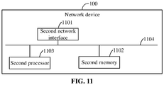
- FIG. 11 a specific hardware composition of the network device 100 provided in the embodiment of the disclosure is shown, which includes a second network interface 1101, a second memory 1102 and a second processor 1103. Each component is coupled together through a bus system 1104. It can be understood that the bus system 1104 is configured to implement connection communication between these components.
- the bus system 1104 includes a data bus and further includes a power bus, a control bus and a state signal bus. However, for clear description, various buses in FIG. 11 are marked as the bus system 1104.
- various buses in FIG. 11 are marked as the bus system 1104.
- the second network interface 1101 is configured to receive and send a signal in a process of receiving and transmitting information from and to another external network element.
- the second memory 1102 is configured to store a computer program capable of running in the second processor 1103.
- the second processor 1103 is configured to run the computer program to implement operations of:
- the second processor 1103 in the network device 100 is further configured to run the computer program to implement the operations of the method in embodiment 2. Elaborations are omitted herein.
Landscapes
- Engineering & Computer Science (AREA)
- Signal Processing (AREA)
- Computer Networks & Wireless Communication (AREA)
- Physics & Mathematics (AREA)
- Mathematical Physics (AREA)
- Mobile Radio Communication Systems (AREA)
Applications Claiming Priority (1)
| Application Number | Priority Date | Filing Date | Title |
|---|---|---|---|
| PCT/CN2018/106218 WO2020056589A1 (zh) | 2018-09-18 | 2018-09-18 | 一种信号传输的方法、装置及计算机存储介质 |
Publications (2)
| Publication Number | Publication Date |
|---|---|
| EP3843348A1 true EP3843348A1 (de) | 2021-06-30 |
| EP3843348A4 EP3843348A4 (de) | 2021-08-25 |
Family
ID=69888064
Family Applications (1)
| Application Number | Title | Priority Date | Filing Date |
|---|---|---|---|
| EP18934022.7A Ceased EP3843348A4 (de) | 2018-09-18 | 2018-09-18 | Signalübertragungsverfahren und -vorrichtung sowie computerspeichermedium |
Country Status (8)
| Country | Link |
|---|---|
| US (1) | US11304159B2 (de) |
| EP (1) | EP3843348A4 (de) |
| JP (1) | JP7182008B2 (de) |
| KR (1) | KR20210057744A (de) |
| CN (2) | CN111357251A (de) |
| AU (1) | AU2018442389A1 (de) |
| SG (1) | SG11202102691PA (de) |
| WO (1) | WO2020056589A1 (de) |
Families Citing this family (5)
| Publication number | Priority date | Publication date | Assignee | Title |
|---|---|---|---|---|
| WO2020087524A1 (zh) * | 2018-11-02 | 2020-05-07 | Oppo广东移动通信有限公司 | 非授权频段上ssb的传输方法和设备 |
| EP4271031A4 (de) * | 2020-12-25 | 2024-03-06 | Beijing Xiaomi Mobile Software Co., Ltd. | Verfahren und vorrichtung zur konfiguration von zeiträumen, kommunikationsvorrichtung und speichermedium |
| US12177897B2 (en) | 2021-03-31 | 2024-12-24 | Apple Inc. | Mitigation of listen before talk conflicts in the unlicensed spectrum |
| CN115529861B (zh) * | 2021-04-26 | 2024-10-25 | 北京小米移动软件有限公司 | 信息传输方法、装置、通信设备和存储介质 |
| CN115622828A (zh) * | 2022-09-30 | 2023-01-17 | 深圳市欧瑞博科技股份有限公司 | 时钟同步方法、装置、系统及智能家居通信设备 |
Family Cites Families (20)
| Publication number | Priority date | Publication date | Assignee | Title |
|---|---|---|---|---|
| US9137075B2 (en) | 2007-02-23 | 2015-09-15 | Telefonaktiebolaget Lm Ericsson (Publ) | Subcarrier spacing identification |
| CN109005019B (zh) * | 2014-12-31 | 2020-01-03 | 华为技术有限公司 | 信号发送和检测装置、系统及方法 |
| WO2016182602A1 (en) * | 2015-05-08 | 2016-11-17 | Intel IP Corporation | Device and method of configurable synchronization signal and channel design |
| KR102375582B1 (ko) * | 2015-10-20 | 2022-03-17 | 삼성전자주식회사 | 통신 디바이스 및 그 제어 방법 |
| CN107295542B (zh) * | 2016-03-31 | 2023-11-03 | 华为技术有限公司 | 信息的传输方法、用户设备和网络设备 |
| PT3823371T (pt) * | 2016-07-01 | 2025-01-07 | Guangdong Oppo Mobile Telecommunications Corp Ltd | Método e dispositivo para deteção de sinal |
| CN107734683B (zh) * | 2016-08-12 | 2021-02-12 | 中兴通讯股份有限公司 | 一种信息传输方法、电子设备及计算机可读存储介质 |
| US11696218B2 (en) * | 2016-10-21 | 2023-07-04 | Qualcomm Incorporated | Multiplexing initial access and data transmissions in assisted millimeter wave systems |
| CN106507439B (zh) * | 2016-10-28 | 2019-12-10 | 宇龙计算机通信科技(深圳)有限公司 | 一种传输信息的方法、基站及终端 |
| CN106455040B (zh) * | 2016-11-30 | 2019-12-10 | 宇龙计算机通信科技(深圳)有限公司 | 一种传输信息的方法、基站及终端 |
| CN108270710A (zh) * | 2017-01-03 | 2018-07-10 | 中兴通讯股份有限公司 | 一种信号传输方法、装置及系统 |
| CN108282859B (zh) * | 2017-01-06 | 2020-10-27 | 华为技术有限公司 | 一种通信方法和装置 |
| CN108282317B (zh) * | 2017-01-06 | 2021-02-05 | 展讯通信(上海)有限公司 | 同步信号块的传输方法、接收方法、基站及用户设备 |
| WO2018145107A1 (en) * | 2017-02-06 | 2018-08-09 | Motorola Mobility Llc | Transmitting and receiving a synchronization signal block |
| US10985964B2 (en) * | 2017-09-11 | 2021-04-20 | Qualcomm Incorporated | Techniques for selecting subcarrier spacing for signal detection |
| CN107528682B (zh) * | 2017-09-20 | 2020-12-22 | 宇龙计算机通信科技(深圳)有限公司 | 参考信号的发送方法及装置 |
| CN108390747B (zh) * | 2018-01-19 | 2021-10-22 | 宇龙计算机通信科技(深圳)有限公司 | 一种同步信号的发送方法和装置 |
| WO2019202196A1 (en) * | 2018-04-18 | 2019-10-24 | Nokia Technologies Oy | Numerology options for new radio |
| KR102509033B1 (ko) * | 2018-05-10 | 2023-03-09 | 삼성전자주식회사 | 무선 통신 시스템에서 채널 접속 방법 및 장치 |
| CN110611948B (zh) * | 2018-06-14 | 2021-01-08 | 维沃移动通信有限公司 | 同步信号块的传输方法、网络设备及终端 |
-
2018
- 2018-09-18 KR KR1020217008579A patent/KR20210057744A/ko not_active Withdrawn
- 2018-09-18 CN CN201880074460.5A patent/CN111357251A/zh active Pending
- 2018-09-18 CN CN202010706474.3A patent/CN111865864B/zh active Active
- 2018-09-18 WO PCT/CN2018/106218 patent/WO2020056589A1/zh not_active Ceased
- 2018-09-18 AU AU2018442389A patent/AU2018442389A1/en not_active Abandoned
- 2018-09-18 SG SG11202102691PA patent/SG11202102691PA/en unknown
- 2018-09-18 JP JP2021538873A patent/JP7182008B2/ja active Active
- 2018-09-18 EP EP18934022.7A patent/EP3843348A4/de not_active Ceased
-
2021
- 2021-03-16 US US17/203,573 patent/US11304159B2/en active Active
Also Published As
| Publication number | Publication date |
|---|---|
| EP3843348A4 (de) | 2021-08-25 |
| WO2020056589A1 (zh) | 2020-03-26 |
| US20210204234A1 (en) | 2021-07-01 |
| KR20210057744A (ko) | 2021-05-21 |
| JP7182008B2 (ja) | 2022-12-01 |
| AU2018442389A1 (en) | 2021-04-15 |
| CN111357251A (zh) | 2020-06-30 |
| SG11202102691PA (en) | 2021-04-29 |
| JP2022509705A (ja) | 2022-01-21 |
| CN111865864A (zh) | 2020-10-30 |
| CN111865864B (zh) | 2022-03-15 |
| US11304159B2 (en) | 2022-04-12 |
Similar Documents
| Publication | Publication Date | Title |
|---|---|---|
| US12010728B2 (en) | Random access method and device | |
| US11304159B2 (en) | Signal transmission method and apparatus and computer storage medium | |
| US11622383B2 (en) | Method and device for channel sensing and signal transmission | |
| US12167357B2 (en) | Method and device for transmitting SSB in an unlicensed spectrum | |
| WO2020107488A1 (zh) | 同步信号块ssb传输方式的确定方法和设备 | |
| RU2768254C2 (ru) | Способ и устройство для передачи информации | |
| US20210250792A1 (en) | Wireless Communication Method and Terminal Device | |
| CN113557702A (zh) | 小区接入的方法和设备 | |
| US20200374887A1 (en) | Channel transmission method and apparatus, and computer storage medium | |
| US20230354231A1 (en) | Signal transmission method and apparatus and computer storage medium | |
| EP3751930B1 (de) | Verfahren und vorrichtung zur übertragung von harq-informationen und computerspeichermedium | |
| RU2773224C1 (ru) | Способ и устройство для передачи сигналов и компьютерный носитель данных |
Legal Events
| Date | Code | Title | Description |
|---|---|---|---|
| STAA | Information on the status of an ep patent application or granted ep patent |
Free format text: STATUS: THE INTERNATIONAL PUBLICATION HAS BEEN MADE |
|
| PUAI | Public reference made under article 153(3) epc to a published international application that has entered the european phase |
Free format text: ORIGINAL CODE: 0009012 |
|
| STAA | Information on the status of an ep patent application or granted ep patent |
Free format text: STATUS: REQUEST FOR EXAMINATION WAS MADE |
|
| 17P | Request for examination filed |
Effective date: 20210326 |
|
| AK | Designated contracting states |
Kind code of ref document: A1 Designated state(s): AL AT BE BG CH CY CZ DE DK EE ES FI FR GB GR HR HU IE IS IT LI LT LU LV MC MK MT NL NO PL PT RO RS SE SI SK SM TR |
|
| REG | Reference to a national code |
Ref country code: DE Ref legal event code: R079 Free format text: PREVIOUS MAIN CLASS: H04L0027260000 Ipc: H04L0005000000 |
|
| A4 | Supplementary search report drawn up and despatched |
Effective date: 20210722 |
|
| RIC1 | Information provided on ipc code assigned before grant |
Ipc: H04L 5/00 20060101AFI20210716BHEP Ipc: H04L 27/26 20060101ALI20210716BHEP |
|
| DAV | Request for validation of the european patent (deleted) | ||
| DAX | Request for extension of the european patent (deleted) | ||
| STAA | Information on the status of an ep patent application or granted ep patent |
Free format text: STATUS: EXAMINATION IS IN PROGRESS |
|
| 17Q | First examination report despatched |
Effective date: 20220404 |
|
| REG | Reference to a national code |
Ref country code: DE Ref legal event code: R003 |
|
| STAA | Information on the status of an ep patent application or granted ep patent |
Free format text: STATUS: THE APPLICATION HAS BEEN REFUSED |
|
| 18R | Application refused |
Effective date: 20230321 |