EP3843379A1 - Dispositif électronique et procédé de commande correspondant - Google Patents
Dispositif électronique et procédé de commande correspondant Download PDFInfo
- Publication number
- EP3843379A1 EP3843379A1 EP19882935.0A EP19882935A EP3843379A1 EP 3843379 A1 EP3843379 A1 EP 3843379A1 EP 19882935 A EP19882935 A EP 19882935A EP 3843379 A1 EP3843379 A1 EP 3843379A1
- Authority
- EP
- European Patent Office
- Prior art keywords
- image sensor
- image
- exposure time
- capture mode
- electronic device
- Prior art date
- Legal status (The legal status is an assumption and is not a legal conclusion. Google has not performed a legal analysis and makes no representation as to the accuracy of the status listed.)
- Granted
Links
Images


Classifications
-
- G—PHYSICS
- G01—MEASURING; TESTING
- G01B—MEASURING LENGTH, THICKNESS OR SIMILAR LINEAR DIMENSIONS; MEASURING ANGLES; MEASURING AREAS; MEASURING IRREGULARITIES OF SURFACES OR CONTOURS
- G01B11/00—Measuring arrangements characterised by the use of optical techniques
- G01B11/02—Measuring arrangements characterised by the use of optical techniques for measuring length, width or thickness
- G01B11/026—Measuring arrangements characterised by the use of optical techniques for measuring length, width or thickness by measuring distance between sensor and object
-
- B—PERFORMING OPERATIONS; TRANSPORTING
- B60—VEHICLES IN GENERAL
- B60W—CONJOINT CONTROL OF VEHICLE SUB-UNITS OF DIFFERENT TYPE OR DIFFERENT FUNCTION; CONTROL SYSTEMS SPECIALLY ADAPTED FOR HYBRID VEHICLES; ROAD VEHICLE DRIVE CONTROL SYSTEMS FOR PURPOSES NOT RELATED TO THE CONTROL OF A PARTICULAR SUB-UNIT
- B60W40/00—Estimation or calculation of non-directly measurable driving parameters for road vehicle drive control systems not related to the control of a particular sub unit, e.g. by using mathematical models
- B60W40/02—Estimation or calculation of non-directly measurable driving parameters for road vehicle drive control systems not related to the control of a particular sub unit, e.g. by using mathematical models related to ambient conditions
-
- G—PHYSICS
- G06—COMPUTING OR CALCULATING; COUNTING
- G06T—IMAGE DATA PROCESSING OR GENERATION, IN GENERAL
- G06T7/00—Image analysis
- G06T7/50—Depth or shape recovery
- G06T7/55—Depth or shape recovery from multiple images
-
- G—PHYSICS
- G06—COMPUTING OR CALCULATING; COUNTING
- G06T—IMAGE DATA PROCESSING OR GENERATION, IN GENERAL
- G06T7/00—Image analysis
- G06T7/70—Determining position or orientation of objects or cameras
-
- G—PHYSICS
- G06—COMPUTING OR CALCULATING; COUNTING
- G06V—IMAGE OR VIDEO RECOGNITION OR UNDERSTANDING
- G06V10/00—Arrangements for image or video recognition or understanding
- G06V10/20—Image preprocessing
- G06V10/25—Determination of region of interest [ROI] or a volume of interest [VOI]
-
- G—PHYSICS
- G06—COMPUTING OR CALCULATING; COUNTING
- G06V—IMAGE OR VIDEO RECOGNITION OR UNDERSTANDING
- G06V20/00—Scenes; Scene-specific elements
- G06V20/50—Context or environment of the image
- G06V20/56—Context or environment of the image exterior to a vehicle by using sensors mounted on the vehicle
-
- H—ELECTRICITY
- H04—ELECTRIC COMMUNICATION TECHNIQUE
- H04N—PICTORIAL COMMUNICATION, e.g. TELEVISION
- H04N23/00—Cameras or camera modules comprising electronic image sensors; Control thereof
- H04N23/45—Cameras or camera modules comprising electronic image sensors; Control thereof for generating image signals from two or more image sensors being of different type or operating in different modes, e.g. with a CMOS sensor for moving images in combination with a charge-coupled device [CCD] for still images
-
- H—ELECTRICITY
- H04—ELECTRIC COMMUNICATION TECHNIQUE
- H04N—PICTORIAL COMMUNICATION, e.g. TELEVISION
- H04N23/00—Cameras or camera modules comprising electronic image sensors; Control thereof
- H04N23/60—Control of cameras or camera modules
- H04N23/667—Camera operation mode switching, e.g. between still and video, sport and normal or high- and low-resolution modes
-
- H—ELECTRICITY
- H04—ELECTRIC COMMUNICATION TECHNIQUE
- H04N—PICTORIAL COMMUNICATION, e.g. TELEVISION
- H04N23/00—Cameras or camera modules comprising electronic image sensors; Control thereof
- H04N23/70—Circuitry for compensating brightness variation in the scene
- H04N23/72—Combination of two or more compensation controls
-
- H—ELECTRICITY
- H04—ELECTRIC COMMUNICATION TECHNIQUE
- H04N—PICTORIAL COMMUNICATION, e.g. TELEVISION
- H04N23/00—Cameras or camera modules comprising electronic image sensors; Control thereof
- H04N23/70—Circuitry for compensating brightness variation in the scene
- H04N23/73—Circuitry for compensating brightness variation in the scene by influencing the exposure time
-
- H—ELECTRICITY
- H04—ELECTRIC COMMUNICATION TECHNIQUE
- H04N—PICTORIAL COMMUNICATION, e.g. TELEVISION
- H04N23/00—Cameras or camera modules comprising electronic image sensors; Control thereof
- H04N23/70—Circuitry for compensating brightness variation in the scene
- H04N23/741—Circuitry for compensating brightness variation in the scene by increasing the dynamic range of the image compared to the dynamic range of the electronic image sensors
-
- H—ELECTRICITY
- H04—ELECTRIC COMMUNICATION TECHNIQUE
- H04N—PICTORIAL COMMUNICATION, e.g. TELEVISION
- H04N23/00—Cameras or camera modules comprising electronic image sensors; Control thereof
- H04N23/90—Arrangement of cameras or camera modules, e.g. multiple cameras in TV studios or sports stadiums
-
- H—ELECTRICITY
- H04—ELECTRIC COMMUNICATION TECHNIQUE
- H04N—PICTORIAL COMMUNICATION, e.g. TELEVISION
- H04N25/00—Circuitry of solid-state image sensors [SSIS]; Control thereof
- H04N25/50—Control of the SSIS exposure
- H04N25/57—Control of the dynamic range
- H04N25/58—Control of the dynamic range involving two or more exposures
- H04N25/581—Control of the dynamic range involving two or more exposures acquired simultaneously
- H04N25/583—Control of the dynamic range involving two or more exposures acquired simultaneously with different integration times
-
- B—PERFORMING OPERATIONS; TRANSPORTING
- B60—VEHICLES IN GENERAL
- B60W—CONJOINT CONTROL OF VEHICLE SUB-UNITS OF DIFFERENT TYPE OR DIFFERENT FUNCTION; CONTROL SYSTEMS SPECIALLY ADAPTED FOR HYBRID VEHICLES; ROAD VEHICLE DRIVE CONTROL SYSTEMS FOR PURPOSES NOT RELATED TO THE CONTROL OF A PARTICULAR SUB-UNIT
- B60W2420/00—Indexing codes relating to the type of sensors based on the principle of their operation
- B60W2420/40—Photo, light or radio wave sensitive means, e.g. infrared sensors
- B60W2420/403—Image sensing, e.g. optical camera
-
- G—PHYSICS
- G06—COMPUTING OR CALCULATING; COUNTING
- G06T—IMAGE DATA PROCESSING OR GENERATION, IN GENERAL
- G06T2207/00—Indexing scheme for image analysis or image enhancement
- G06T2207/30—Subject of image; Context of image processing
- G06T2207/30248—Vehicle exterior or interior
- G06T2207/30252—Vehicle exterior; Vicinity of vehicle
Definitions
- This disclosure relates to an electronic device and a method for controlling thereof and, more specifically, to an electronic device for obtaining visibility and distance information by using a multi-camera and a method for controlling thereof.
- HDR high dynamic range
- a minimum of three cameras may be required. For example, two cameras may be required to implement the HDR technology, and two cameras may be required to calculate distance information of an object using a stereo camera. Even if one of the cameras is used to implement the HDR technology and is used as a stereo camera, three cameras may be required as described above.
- the disclosure has been made to solve the above-described problems, and an object of the disclosure is to provide an electronic device for identifying an object in an image obtained through the HDR technology using a multi-camera, and obtaining distance information of the identified object, and a method for controlling thereof.
- an electronic device may include a first image sensor, a second image sensor, and a processor.
- the processor may alternately perform a first image capture mode, in which a plurality of captured images are obtained by controlling respective exposure times of the first image sensor and the second image sensor differently, and a second image capture mode, in which a plurality of captured images are obtained by controlling respective exposure times of the first image sensor and the second image sensor identically.
- the processor may identify an object by using the plurality of captured images obtained in the first image capture mode and obtain distance information about the identified object based on the plurality of captured images obtained in the second image capture mode.
- the processor may control an exposure time of the first image sensor to a first exposure time in the first capture mode and control an exposure time of the second image sensor to a second exposure time.
- the processor may control the exposure times of the first and second image sensors to the first exposure time in the second capture mode.
- the second exposure time may exceed the first exposure time.
- the processor may update the first exposure time based on at least one of a pixel value and position information of the object included in at least one previous image obtained by the first image sensor.
- the processor may update the second exposure time based on at least one of a pixel value and position information of the object included in at least one previous image obtained by the second image sensor in the first capture mode.
- the processor may alternately perform the first capture mode and the second capture mode in a preset frame interval.
- the processor may, based on a pixel value included in an image obtained by the second image sensor in the first capture mode being less than a preset value, control the exposure time of the second image sensor to exceed a time period corresponding to a frame.
- the electronic device may be a driving assistant device mounted on a vehicle.
- the processor may control the vehicle based on at least one of type information and distance information of the object.
- the processor may generate a high dynamic range (HDR) image using a plurality of captured images obtained in the first capture mode and identify the object by using the HDR image.
- HDR high dynamic range
- a method for controlling an electronic device includes alternately performing a first image capture mode, in which a plurality of captured images are obtained by controlling respective exposure times of the first image sensor and the second image sensor differently, and a second image capture mode, in which a plurality of captured images are obtained by controlling respective exposure times of the first image sensor and the second image sensor identically and identifying an object by using the plurality of captured images obtained in the first image capture mode and obtaining distance information about the identified object based on the plurality of captured images obtained in the second image capture mode.
- the alternately performing may include controlling an exposure time of the first image sensor to a first exposure time in the first capture mode and controlling an exposure time of the second image sensor to a second exposure time.
- the alternately performing may include controlling the exposure times of the first and second image sensors to the first exposure time in the second capture mode.
- the second exposure time may exceed the first exposure time.
- the method may further include updating the first exposure time based on at least one of a pixel value and position information of the object included in at least one previous image obtained by the first image sensor and updating the second exposure time based on at least one of a pixel value and position information of the object included in at least one previous image obtained by the second image sensor in the first capture mode.
- the alternately performing may include alternately performing the first capture mode and the second capture mode in a preset frame interval.
- the alternately performing may include, based on a pixel value included in an image obtained by the second image sensor in the first capture mode being less than a preset value, controlling the exposure time of the second image sensor to exceed a time period corresponding to a frame.
- the electronic device may be a driving assistant device mounted on a vehicle.
- the method may further include controlling the vehicle based on at least one of type information and distance information of the object.
- the obtaining the distance information may include generating a high dynamic range (HDR) image using a plurality of captured images obtained in the first capture mode and identifying the object by using the HDR image.
- HDR high dynamic range
- a non-transitory computer readable medium storing computer instructions executed by a processor of an electronic device to cause the electronic device to perform operations including alternately performing a first image capture mode, in which a plurality of captured images are obtained by controlling respective exposure times of the first image sensor and the second image sensor differently, and a second image capture mode, in which a plurality of captured images are obtained by controlling respective exposure times of the first image sensor and the second image sensor identically and identifying an object by using the plurality of captured images obtained in the first image capture mode and obtaining distance information about the identified object based on the plurality of captured images obtained in the second image capture mode.
- an electronic device may capture an image through a multi-camera having different exposure times to increase the accuracy of identifying an object.
- the electronic device may capture the image through the time difference of the multi-camera to obtain accurate distance information of the identified object.
- the electronic device may identify the object and obtain distance information of the object by using only two cameras.
- one element e.g., a first element
- another element e.g., a second element
- a component e.g., a first component
- module such as “module,” “unit,” “part,” and so on may be used to refer to an element that performs at least one function or operation, and such element may be implemented as hardware or software, or a combination of hardware and software. Further, except for when each of a plurality of “modules,” “units,” “parts,” and the like needs to be realized in an individual hardware, the components may be integrated in at least one module or chip and may be realized in at least one processor (not shown).
- a term "user” may refer to a person using an electronic device, or a device (for example, an artificial intelligence electronic device) using an electronic device.
- FIG. 1 is a diagram illustrating an electronic device to obtain as peripheral image including various objects to facilitate understanding of the disclosure.
- the electronic device 100 may monitor a surrounding environment using a plurality of image sensors 110-1 and 110-2.
- the electronic device 100 is a driving assistant device mounted on a vehicle, and may be a device implementing advanced driver assistance systems (ADAS).
- ADAS advanced driver assistance systems
- the electronic device 100 may be implemented as an electrical system of a vehicle and may be implemented as a camera module installed inside a vehicle.
- the electronic device 100 may be implemented as a room mirror integrated module, or may be implemented with a portable device such as a black box, a mobile phone, and a personal digital assistant (PDA) detachable from the vehicle.
- PDA personal digital assistant
- the electronic device 100 may obtain an image 10 which captures a surrounding environment, a front road situation, or the like, by using a plurality of image sensors 110-1, 110-2.
- the image sensor 110 is configured to capture a surrounding environment and may be referred to as a camera, a sensor, a capturing sensor, etc., and will be referred to as an image sensor for convenience.
- the electronic device 100 may identify an object included in an image obtained through each of the plurality of image sensors 110-1 and 110-2, and obtain distance information of the identified object, and various embodiments will be described in detail with reference to the drawings.
- FIG. 2 is a block diagram illustrating a configuration of an electronic device according to an embodiment.
- the electronic device 100 includes an image sensor 110 including a first image sensor 110-1 and a second image sensor 110-2, and a processor 120.
- the image sensor 110 is configured to obtain an image.
- the image sensor may convert light incident through a lens into an electric image signal to obtain a captured image.
- the image sensor 110 may be implemented as a charge coupled device (CCD) sensor or a complementary metal oxide semiconductor (CMOS) sensor, but is not limited thereto.
- CCD charge coupled device
- CMOS complementary metal oxide semiconductor
- Images of different brightness may be obtained according to the exposure time of the image sensor 110.
- the exposure time may refer to the time when a shutter (not shown) connected to the image sensor 110 is opened to receive light.
- the exposure time of the image sensor 110 may be adjusted differently based on the surrounding environment.
- the exposure time may be adjusted relatively long to obtain a bright image when the surrounding environment is dark.
- the intensity of the light incident through the lens may be sensed, or the ambient illumination may be identified based on the pixel information of the captured image.
- the image sensor 110 may be mounted on a vehicle.
- the first image sensor 110-1 and the second image sensor 110-2 may be spaced apart from each other to have different capturing times.
- the image sensors may be arranged so as to capture a front at both ends of a room mirror.
- the first image sensor 110-1 and the second image sensor 110-2 may be spaced apart from each other at predetermined interval and arranged at various positions as well as the room mirror.
- the first image sensor 110-1 and the second image sensor 110-2 may be arranged to capture the front at both ends of one of both side mirrors.
- the first image sensor 110-1 and the second image sensor 110-2 may be arranged to capture the front in each of the both side mirrors.
- the processor 120 may control overall operations of the electronic device 100.
- the processor 120 may be implemented as, for example, a digital signal processor (DSP) for processing of a digital signal, a microprocessor, a time controller (TCON), or the like, but this is not limited thereto.
- the processor 120 may include, for example, and without limitation, one or more of a central processor (CPU), a micro controller unit (MCU), a micro-processor (MPU), a controller, an application processor (AP), a communication processor (CP), an advanced reduced instruction set computing (RISC) machine (ARM) processor, an artificial intelligence (AI) processor, or may be defined as a corresponding term.
- the processor 120 may be implemented in a system on chip (SoC) type or a large scale integration (LSI) type which a processing algorithm is built therein, or in a field programmable gate array (FPGA) type.
- SoC system on chip
- LSI large scale integration
- FPGA field programmable gate array
- the processor 120 may alternately perform a first capture mode to obtain a plurality of captured image by controlling the exposure times of each of the first image sensor 110-1 and the second image sensor 110-2 differently and a second capture mode to obtain a plurality of captured images by controlling the exposure times of each of the first image sensor 110-1 and the second image sensor 110-2 equally.
- the processor 120 may alternately perform a first capture mode and a second capture mode at a predetermined frame interval.
- the first capture mode and the second capture mode may be alternately performed at intervals of one frame or at least two frames.
- the processor 120 may identify an object using a plurality of captured images obtained through the first image sensor 110-1 and the second image sensor 110-2 at the first capture mode.
- the brightness of the image obtained from each of the first image sensor 110-1 and the second image sensor 110-2 may be different.
- the discrimination of an object may be increased when identifying an object in a captured image with various brightness than identifying an object from an image captured with one brightness.
- the processor 120 may accurately identify the various objects in a plurality of captured images obtained from each of the first image sensor 110-1 and the second image sensor 110-2, of which exposure times are controlled differently.
- the processor 120 may synthesize the plurality of captured images obtained from each of the first image sensor 110-1 and the second image sensor 110-2 as one image and identify various objects in the composite image.
- the composite image may be an image in which a bright region is adjusted to be brighter, and a dark region is adjusted to be darker so that a contrast ratio may be high.
- the processor 120 may obtain an object from an image with an increased dynamic range.
- the composite image in which the plurality of captured images obtained from the first image sensor 110-1 and the second image sensor 110-2 are composited to one image may be an HDR image.
- the processor 120 may generate the HDR image using the plurality of captured images obtained in the first capture mode, and identify the object by using the HDR image.
- the HDR image may be an image in which a bright region is displayed to be brighter, and a dark region is displayed to be darker so that a range of brightness on an image is extended.
- the object may be an object of interest (or a region of interest).
- the processor 120 may identify an object of interest from the obtained plurality of captured images.
- an object of interest may be an object that needs to be cautioned when traveling, such as a crosswalk, traffic lights, a traffic sign, a person, a vehicle, or the like, but this is only one example.
- a storage (not shown) may store information about an object of interest, and the processor 120 may obtain this information from the storage to identify the object in the captured image.
- an object may be identified by searching a pixel value similar to the pixel value of an image of the object of interest stored in the storage by applying a search window to the captured image.
- the electronic device 100 may include a separate training model in which the object information is trained, and the processor 120 may apply the captured image to the training model to identify the object.
- the training model may be implemented as a cognitive system, such as an artificial neural network or a neuromorphic processor.
- the same training model may be applied to the first image captured by the first image sensor 110-1 and the second image captured by the second image sensor 110-2, but different training models may be applied to the first and second images.
- the pixel values of the first and second images may be different and the pixel values of each object included may be different.
- a first training model trained with samples having a pixel value similar to the image captured by the first image sensor 110-1 may be applied to the first image
- a second training model trained with samples having a pixel value similar to the image captured by the second image sensor 110-2 may be applied to the second image to identify the object.
- the processor 120 may aggregate the object information identified in the first image and the object information identified in the second image to finally identify the object. For example, if the first object and the second object are identified in the first image and the second object and the third object are identified in the second image, the first through third objects may be finally identified objects.
- the processor 120 may obtain distance information of the identified object based on the plurality of captured images obtained from the second capture mode.
- the processor 120 may obtain distance information of an object included in a plurality of images using this time difference.
- the object is an object identified in the first capture mode.
- a technology for calculating distance information of an object by using a time difference between a plurality of image sensors corresponds to a stereo disparity technology, which is a well-known art, and thus a detailed description thereof will be omitted.
- the second capture mode does not need to control the exposure time of the first image sensor 110-1 and the second image sensor 110-2 differently since the second capture mode is a mode for obtaining distance information of the object identified in the first capture mode through the stereo disparity technology.
- the processor 120 may control the exposure time of the first image sensor to 110-1 to a first exposure time in the first capture mode, and control the exposure time of the second image sensor 110-2 to a second exposure time.
- the processor 120 may control the exposure time of the first image sensor 110-1 and the second image sensor 110-2 to a first exposure time in a second capture mode.
- the first exposure time is a time calculated based on the image information obtained from the first image sensor 110-1
- the second exposure time may be a time calculated based on the image information obtained from the second image sensor 110-2.
- the image information may include a pixel value of the captured image, a location information of an object included in the captured image, a gamma value, international standards organization (ISO) gain, or the like.
- the first exposure time and the second exposure time may be updated every mode to be performed alternately and will be described later.
- the processor 120 may control the exposure time of the second image sensor 110-2 in the second capture mode to be the same as the exposure time of the first image sensor 110-1. Specifically, in the second capture mode, the processor 120 may apply the first exposure time calculated based on the image information obtained from the first image sensor 110-1 to the second image sensor 110-2.
- the processor 120 may not obtain an exposure time based on image information obtained from the second image sensor 110-2 in a second capture mode, and thus, there may be an effect of reducing the computational amount of the processor 120.
- the second exposure time may exceed the first exposure time.
- the processor 120 may obtain a bright image from the second image sensor 110-2 than the image obtained from the first image sensor 110-1.
- the target pixel value of the second image sensor 110-2 is set to be higher than the target pixel value of the first image sensor 110-1
- the second image sensor 110-2 may obtain a brighter image than the first image sensor 110-1 in the same illuminance environment of the first capture mode.
- the target pixel value may be a pixel value targeted by the pixel value included in the captured image obtained from each image sensor.
- the processor 120 may update the exposure time of each image sensor to reach the target pixel value, and this will be described later.
- the second image sensor 110-2 may obtain a relatively bright image.
- the processor 120 may update the first exposure time and the second exposure time based on the previous image information of the captured image obtained by the first image sensor 110-1 and the second image sensor 110-2.
- the processor 120 may update the first exposure time based on at least one of a pixel value included in at least one previous image obtained by the first image sensor and location information of the object.
- the processor 120 may calculate an average value of a pixel value included in at least one previous image obtained by the first image sensor 110-1 (hereinafter, an average pixel value) and may control the exposure time so that the calculated average pixel value reaches a target pixel value.
- the average pixel value may be calculated using a mean value algorithm. Since the mean value algorithm is a well-known art, detailed description thereof is omitted.
- the target pixel value may be prestored in a device or changed according to an illuminance environment.
- the exposure time of the first image sensor 110-1 may be 15 ms. If the average pixel value of the at least one image obtained by the first image sensor 110-1 is greatly different from the target pixel value than the above-described example, the processor 120 may update the exposure time of the first image sensor to 33 ms. The processor 120 may update the first exposure time by comparing the average pixel value of the at least one image obtained by the first image sensor 110-1 and the target pixel value of the first image sensor 110-1.
- the exposure time information corresponding to the average pixel value of at least one image obtained by the first image sensor 110-1 may be stored in a storage (not shown), and the processor 120 may obtain exposure time information from the storage based on the calculated average pixel value to update the first exposure time.
- the processor 120 may update the exposure time based on the location information of the object included in the image. If the average pixel value of the image is used, a specific object may not be identified. For example, a case where the target pixel value of the first image sensor 110-1 is 127 and a situation that the first image sensor 110-1 captures the surrounding environment is a backlight situation. In the backlight situation, an image in which a specific object is dark and the surroundings of the specific object is bright may be obtained. In this example, the average pixel value of the obtained image may be calculated close to 127 so that the processor 120 may update the first exposure time to be short. The processor 120 may not accurately identify the type of the specific object included in the image obtained according to the updated exposure time. Accordingly, the processor 120 may update the exposure time considering the location information of the object included in the image.
- the processor 120 may assign a weight to a pixel value of an area in which an object is arranged based on the location information of the object included in the image. For example, if an object included in an image is arranged in a central region of an image, the processor 120 may assign a weight to the pixel value of the central region. Accordingly, the processor 120 may update the exposure time of the first image sensor 110-1 to clearly identify the object located in the central region.
- the processor 120 may update the second exposure time based on at least one of a pixel value included in at least one previous image obtained by the second image sensor 110-2 in the first capture mode and location information of the object.
- the second exposure time applied to the second image sensor 110-2 may be updated in the same manner to the first exposure time. However, it may be different in that the processor 120 updaters the second exposure time based on the image information of the image captured by the second image sensor 110-2 in the first capture mode.
- the processor 120 may update the first exposure time based on at least one of the pixel values and the object location information of the at least one previous image captured from the first image sensor 110-1 in the first and second capture modes, but may update the second exposure time based on the pixel values and the location information of the object in the images obtained in the first capture mode of the at least one previous image captured from the second image sensor 110-1.
- the second image sensor 110-2 may obtain an image by alternately using the first exposure time calculated based on image information obtained from the first image sensor 110-1 according to the capture mode and the second exposure time calculated based on image information obtained from the second image sensor 110-2.
- the processor 120 my independently calculate and update the first exposure time and the second exposure time, as in the embodiments described above.
- the processor 120 may perform the first capture mode and the second capture mode alternately at a preset frame interval. If the preset event does not occur, the processor 120 may alternately perform the first capture mode and the second capture mode at a frame interval. For example, based on 30fps, the exposure time of the image sensor 110 per frame cannot exceed 33ms. The processor 120 may update the exposure time within 33ms based on at least one of the pixel values and the location information of the object included in at least one previous image obtained by the image sensor 110.
- the processor 120 may control the exposure time of the image sensor 110 to exceed a time period corresponding to one frame.
- the preset event may be an event that a pixel value included in an image obtained by the second image sensor 110-2 in the first capture mode is less than a preset value. That is, when the average pixel value of the at least one previous image obtained by the second image sensor 110-2 is less than the preset value, the processor 120 may control the exposure time of the second image sensor 110-2 to exceed a time period corresponding to one frame.
- the processor 120 may control the exposure time to reach the target pixel value by setting the exposure time to be long even if the maximum exposure time per frame is exceeded.
- the second image sensor 110-2 may obtain a captured image.
- the fps of the second image sensor 110-21 may be lower than the fps of the first image sensor 110-1.
- the processor 120 may obtain an image with a high contrast ratio from the first image sensor 110-1 and the second image sensor 110-2.
- the processor 120 may repeat the first capture mode and the second capture mode by turns to identify the object with only the two image sensors and may obtain the distance information of the identified object.
- the processor 120 may control a vehicle on which the electronic device 100 is mounted based on at least one of the type information and the distance information of the object. For example, if an object included in the captured image is identified as a traffic sign which limits the highest speed, the processor 120 may control the speed of the vehicle so as not to exceed the highest speed, or if the object included in the captured image is traffic lights, the processor 120 may identify a signal of the traffic lights to control the vehicle. When the distance of the object is less than a predetermined distance based on the distance information of the object included in the captured image, braking of the vehicle may be performed.
- the electronic device 100 is a device mounted on a vehicle, or may be a device used to identify the object regardless of the vehicle and calculate the distance information of the identified object.
- FIG. 2 illustrates the electronic device 100 including the image sensor 110 and the processor 120, but the electronic device 100 may be implemented in a form excluding the image sensor 110.
- the electronic device is composed of a memory and/or a processor, and the captured image may be obtained through an interface connected to an external image sensor.
- FIG. 3 is a block diagram illustrating an example of a detailed configuration of an electronic device according to an embodiment.
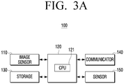
- the electronic device 100 includes the image sensor 110, the processor 120, a communicator 130, a storage 140, and a sensor 150.
- the image sensor 110 the image sensor 110
- the processor 120 the processor 120
- a communicator 130 the image sensor 110
- a storage 140 the electronic device 100
- a sensor 150 the sensor 150.
- FIG. 3A detailed description of the structure as shown in FIG. 2 is omitted.
- the processor 120 controls overall operations of the electronic device 100 using various programs stored in the memory 140.
- the processor 120 includes at least one of a random access memory (RAM) 121, a read-only memory (ROM) 122, a main central processing unit (CPU) 123, a first to n th interfaces 124-1 ⁇ 124-n, and a bus 125.
- RAM random access memory
- ROM read-only memory
- CPU main central processing unit
- the RAM 121, the ROM 122, the main CPU 123, the first to n th interfaces 124-1 to 124-n, or the like, may be interconnected through the bus 125.
- the ROM 122 stores one or more instructions for booting the system and the like.
- the CPU 123 copies the OS stored in the storage 140 to the RAM 121 according to the stored one or more instructions in the ROM 122, and executes the OS to boot the system.
- the CPU 123 copies various application programs stored in the storage 140 to the RAM 121, executes the application program copied to the RAM 121, and performs various operations.
- the main CPU 123 accesses the storage 140 and performs booting using an operating system (OS) stored in the storage 140, and performs various operations using various programs, contents data, or the like, stored in the storage 140.
- OS operating system
- the first to n th interface 124-1 to 124-n are connected to the various elements described above.
- One of the interfaces may be a network interface connected to an external device through the network.
- the communicator 130 may communicate with an external electronic device (not shown) or an external server (not shown).
- the communicator 130 may perform communication with an external server according to wired/wireless communication method and may use a communication method such as a BlueTooth (BT), wireless fidelity (WI-FI), Zigbee, infrared (IR), Ethernet, serial interface, universal serial bus (USB), near field communication (NFC), vehicle to everything (V2X), cellular, or the like.
- BT BlueTooth
- WI-FI wireless fidelity
- IR infrared
- Ethernet serial interface
- USB universal serial bus
- NFC near field communication
- V2X vehicle to everything
- the communicator 130 may receive the object information from an external server.
- the communicator 130 may transmit a control command to a vehicle controller (not shown) according to the control of the processor 120.
- a vehicle controller (not shown) according to the control of the processor 120.
- the communicator 130 may transmit a command relative to the vehicle speed, a command relative to braking the vehicle, or the like, to the vehicle controller.
- the communicator 130 may receive a captured image obtained from an external image sensor.
- the storage 140 may store various data, programs, or applications for driving/controlling the electronic device 100.
- the storage 140 may store the control program for controlling the electronic device 100 and the processor 120, applications that are initially provided by a manufacturer or downloaded from the outside, databases, or related data.
- the storage 140 may store the plurality of captured images obtained from the first image sensor 110-1 and the second image sensor 110-2. A plurality of captured images stored in the storage 140 may be used in the process of updating the exposure time of the first image sensor 110-1 and the second image sensor 110-2.
- the storage 140 may store the exposure time information corresponding to the average pixel value of the obtained image by the image sensor 110 as a format of a look-up table.
- the storage 140 may store information about at least one of a region of interest and an object of interest.
- the storage 140 may store type information of the traffic sign and the type information of the traffic lights, or the like.
- the type information stored in the storage 140 may be used for the processor 120 to identify the object included in the captured image.
- the electronic device 100 may include a separate training model in which the type information is trained, and may apply the captured image to the training model to identify the object.
- the training model may be implemented as a cognitive system, such as an artificial neural network or a neuromorphic processor.
- the storage 140 may be implemented as an internal memory such as a ROM, a RAM, etc. included in the processor 120, or may be implemented with a memory separate from the processor 120.
- the storage 140 may be implemented as a non-volatile memory, a volatile memory, a hard disk drive (HDD), or a solid state drive (SSD).
- the sensor 150 may detect input of various types.
- the sensor 150 may be a touch sensor for detecting a user's touch, and the sensor 150 according to the disclosure may include various sensors such as an illuminance sensor, a motion sensor, or the like.
- the electronic device 100 described above may be used independently but may be used to identify a specific object along with a RAadio Detection And Ranging (RADAR) unit, a LIght Detection And Ranging (LIDAR) unit, and calculate distance information of the identified object.
- the RADAR unit may be a sensor configured to detect objects in the environment in which the vehicle is located by using a wireless signal.
- the RADAR unit may be configured to detect the speed and/or direction of the objects.
- the LIDAR unit may be a sensor configured to detect objects in the environment in which the vehicle is located using a laser.
- the electronic device 100 may additionally include a display (not shown).
- the display may display the captured image obtained from the image sensor 110.
- the display may display various content including vehicle driving information, or the like.
- vehicle driving information may include the current speed of the vehicle, the speed limit of the road on which the vehicle is currently driving, traffic sign information, or the like.
- the display may be implemented with various forms such as a liquid crystal display (LCD), an organic light-emitting diode (OLED), liquid crystal on silicon (LCoS), digital light processing (DLP), quantum dot (QD) display panel, micro LED, or the like.
- the display may be implemented in a touch screen to form a layer structure with a touch pad.
- the display may be used as a user interface (not shown) in addition to the output device.
- the touch screen may be configured to detect the touch input pressure as well as the touch input position and area.
- the electronic device 100 may not include a display separately, and may be connected to an external display device through an interface (not shown) to transmit a signal corresponding to various contents to an external display device.
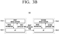
- FIG. 3B is a diagram illustrating an example of an image sensor according to an embodiment.
- each of the first image sensor 110-1 and the second image sensor 110-2 may be connected to a separate processor, and the processor may be implemented as an application processor (AP).
- AP application processor
- An application processor connected to the first image sensor 110-1 may be referred to as a first application processor 120-1 and an application processor connected to the second image sensor 110-2 may be referred to as a second application processor 120-2.
- the application processors 120-1 and 120-2 may update the exposure time based on the image information of each of image sensors 110-1 and 110-2, and may apply the updated exposure time to each of image sensor 110-1 and 110-2 to obtain a captured image.
- the first application processor 120-1 ay update the first exposure time based on image information of at least one previous image obtained by the first image sensor 110-1 and may transmit the updated first exposure time information to the second application processor 120-2 through an internal interface (not shown).
- the internal interface may be implemented with a wired cable.
- the embodiment is not limited thereto and the internal interface may be implemented as a wireless communication module such as a BlueTooth (BT), a Wireless Fidelity (WI-FI), or the like.
- the second application processor 120-2 may control the exposure time of the second image sensor 110-2 in the first capture mode based on the received first exposure time information to obtain a captured image.
- the first application processor 120-1 may transmit the first exposure time information to the second application processor 120-2 through an external interface.
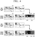
- FIG. 4 is a diagram illustrating an operation of alternately performing a first capture mode and a second capture mode according to an embodiment.
- the electronic device 100 may perform a first capture mode to obtain a plurality of captured images 405 and 410 by controlling the exposure time of each of the first image sensor 110-1 and the second image sensor 110-2 differently.
- the brightness of the image 405 obtained from the first image sensor 110-1 and the image 410 obtained from the second image sensor 110-2 may be different.
- the electronic device 100 may control the exposure time of the first image sensor 110-1 to the first exposure time (e.g., 5 ms) in the first capture mode, and control the exposure time of the second image sensor 110-2 to a second exposure time (e.g., 30 ms). Since the second exposure time exceeds the first exposure time, the image 410 obtained from the second image sensor 110-2 may be an image brighter than the image 405 obtained from the first image sensor 110-1.
- the electronic device 100 may identify an object in the plurality of captured images 405, 410 obtained in the first capture mode.
- the electronic device 100 may have higher discrimination in a case of identifying an object from an image captured with various brightness, rather than a case of identifying an image captured with single brightness.
- the electronic device 100 may identify different objects from the image obtained from the first image sensor 110-1 and the image obtained from the second image sensor 110-2. As shown in FIG. 4 , the electronic device 100 may identify a traffic light region in the image 405 obtained from the first image sensor 110-1, but may not identify the image in the image 410 obtained from the second image sensor 110-2. The electronic device may identify a plurality of vehicles in the image 410 obtained from the second image sensor 110-2, but may identify only one vehicle in the image 405 obtained from the first image sensor 110-1.
- the electronic device 100 may perform a second capture mode to obtain a plurality of captured images 415, 420 by controlling the exposure time of each of the first image sensor 110-1 and the second image sensor 110-2 identically.
- the electronic device 100 may control the exposure time of the second image sensor 110-2 to be the same as the exposure time of the first image sensor 110-1. Therefore, as shown in FIG. 4 , the image 415 obtained from the first image sensor 110-1 and the image 420 obtained from the second image sensor 110-2 may have the same brightness.
- the electronic device 100 does not obtain the exposure time based on image information obtained from the second image sensor 110-2 in the second capture mode, and thus, there may be an effect of reducing the computational amount of the electronic device 100.
- the electronic device 100 may obtain the distance information of an object included in the plurality of captured images 405, 410 using the time difference.
- the object may refer to all objects identified in a plurality of images 405, 410 of the first capture mode.
- the electronic device 100 may alternately perform the first capture mode and the second capture mode by frames.
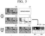
- FIG. 5 is a diagram illustrating an operation that an exposure time of a second image sensor exceeds a time period corresponding to a frame according to an embodiment.
- the electronic device 100 may alternately perform the first capture mode and the second capture mode by one frame interval.
- the electronic device 100 may control the exposure time of the second image sensor 110-2 to exceed a time period corresponding to one frame.
- the electronic device 100 may obtain an image having a target pixel value by setting the exposure time to exceed the maximum exposure time per frame, as shown in FIG. 5 . Accordingly, the second image sensor 110-2 may obtain a captured image 515 while the first capture mode is performed during a plurality of frames and the first image sensor 110-1 obtains a plurality of captured images 505, 510.
- the exposure of a shutter 514 connected to the second image sensor 110-2 may be continued while the first image sensor 110-1 obtains the captured image 505, and the second image sensor 110-2 may obtain one captured image 515 in a state where the exposure time is adjusted to be relatively long.
- the fps of the second image sensor 110-2 may be lower than the fps of the first image sensor 110-1.
- the electronic device 100 may perform the second capture mode to obtain a plurality of captured images 520, 525 by controlling the exposure time of each of the first image sensor 110-1 and the second image sensor 110-2 identically, and may obtain distance information of the object included in the plurality of captured images 520, 525.
- the exposure time of the first image sensor 110-1 is described as a time period corresponding to two frames, but the exposure time may be a time period corresponding to three or more frames according to the illuminance situation.
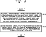
- FIG. 6 is a flowchart illustrating a method for controlling an electronic device according to an embodiment.
- the electronic device may alternately perform the first capture mode to obtain a plurality of captured images by controlling exposure times of each of the first image sensor 110-1 and the second image sensor 110-2 differently and the second capture mode to obtain a plurality of captured images by controlling the exposure times of each of the first image sensor 110-1 and the second image sensor 110-2 identically in operation S610.
- the electronic device may control the exposure time of the first image sensor 110-1 to the first exposure time in the first capture mode, and control the exposure time of the second image sensor 110-2 to the second exposure time.
- the electronic device may control the exposure time of the first image sensor 110-1 and the second image sensor 110-2 to the first exposure time in the second capture mode.
- the electronic device may control the exposure time of the second image sensor 110-2 in the second capture mode to be the same as the exposure time of the first image sensor 110-1. Accordingly, the electronic device does not obtain the exposure time based on the image information obtained from the second image sensor 110-2 in the second capture mode and thus, there may be an effect of reducing the computational amount of the electronic device 100.
- the second exposure time may exceed the first exposure time.
- the second image sensor 110-2 is set to have a longer exposure time than the first image sensor 110-1 in the first capture mode so that the electronic device may obtain a brighter image than the image obtained from the first image sensor 110-1.
- the electronic device may update the first exposure time based on at least one of a pixel value included in at least one previous image and location information of the object obtained by the first image sensor 110-1. For example, the electronic device 100 may calculate an average pixel value included in at least one previous image obtained by the first image sensor 110-1 and control the exposure time so that the calculated average pixel value reaches a target pixel value. Alternatively, exposure time information corresponding to an average pixel value of at least one image obtained by the first image sensor 110-1 may be stored, and the electronic device may obtain stored exposure time information based on the calculated average pixel value and update the first exposure time.
- the electronic device may update the second exposure time based on at least one of a pixel value included in at least one previous image obtained by the second image sensor 110-2 in the first capture mode and location information of the object.
- the second exposure time applied to the second image sensor 110-2 may be updated in the same manner to the first exposure time.
- the electronic device 100 may update the second exposure time based on the image information of the image captured by the second image sensor 110-2 in the first capture mode.
- the electronic device may alternately perform a first capture mode and a second capture mode at a predetermined frame interval.
- the preset frame interval may be one frame interval.
- the exposure time of the second image sensor 110-2 may be controlled to exceed a time interval corresponding to one frame.
- the electronic device may identify the object using the plurality of captured images obtained in the first capture mode, and obtain the distance information of the identified object based on the plurality of captured images obtained in the second capture mode in operation S620.
- the electronic device 100 may have a high discrimination of an object when identifying an object from an image captured with various brightness than identifying an object from an image captured with one brightness.
- the electronic device 100 may accurately identify various objects in the plurality of captured images obtained from each of the first image sensor 110-1 and the second image sensor 110-2 of which exposure times are controlled differently from each other.
- the electronic device 100 may obtain distance information of an object included in a plurality of images by using this time difference.
- S620 may be performed simultaneously with S610 or after S610.
- the electronic device described above may be a driving assistance device mounted on a vehicle.
- the electronic device may be a device implementing Advanced Driver Assistance Systems (ADAS).
- ADAS Advanced Driver Assistance Systems
- the electronic device may be an electronic system of a vehicle, and may be implemented as a camera module installed inside a vehicle, a room mirror integrated module, or a black box detachable from the vehicle, or the like.
- the electronic device may control the vehicle based on at least one of the type information and distance information of the object.
- the electronic device includes the image sensor 110 and the processor 120, but according to an embodiment, the electronic device may be implemented in a form excluding the image sensor 110.
- the electronic device may be composed of a memory and/or a processor, and the captured image may be obtained through an interface connected to the external image sensor.
- At least some of the methods according to various embodiments described above may be installed in an existing electronic device, and may be implemented in an application form which is a software that is directly used by a user on the OS.
- the methods according to the various embodiments as described above may be implemented as software upgrade or hardware upgrade for an existing electronic device.
- the various embodiments described above may be performed through an embedded server provided in an electronic device, or an external server of at least one electronic device and a display device.
- various embodiments may be implemented in software, including instructions stored on machine-readable storage media readable by a machine (e.g., a computer).
- An apparatus may call instructions from the storage medium, and execute the called instruction, including an electronic apparatus (for example, an electronic device A) according to the disclosed embodiments.
- the processor may perform a function corresponding to the instructions directly or by using other components under the control of the processor.
- the instructions may include a code generated by a compiler or a code executable by an interpreter.
- a machine-readable storage medium may be provided in the form of a non-transitory storage medium.
- non-transitory only denotes that a storage medium is tangible, and does not distinguish the case in which a data is semi-permanently stored in a storage medium from the case in which a data is temporarily stored in a storage medium.
- the method according to the above-described embodiments may be included in a computer program product.
- the computer program product may be traded as a product between a seller and a consumer.
- the computer program product may be distributed online in the form of machine-readable storage media (e.g., compact disc read only memory (CD-ROM)) or through an application store (e.g., Play StoreTM) or distributed online directly.
- CD-ROM compact disc read only memory
- application store e.g., Play StoreTM
- at least a portion of the computer program product may be at least temporarily stored or temporarily generated in a server of the manufacturer, a server of the application store, or a machine-readable storage medium such as memory of a relay server.
- one or more embodiments described above may be implemented in a computer readable medium, such as a computer or similar device, using software, hardware, or combination thereof.
- the one or more embodiments described herein may be implemented by the processor itself.
- embodiments such as the procedures and functions described herein may be implemented with separate software modules. Each of the software modules may perform one or more of the functions and operations described herein.
- Non-transitory computer-readable medium is a medium that semi-permanently stores data and is readable by the apparatus. Examples of non-transitory computer-readable media may include CD, DVD, hard disk, Blu-ray disk, USB, memory card, ROM, or the like.
- the method according to the above-described embodiments may be included in a computer program product.
- the computer program product may be traded as a product between a seller and a consumer.
- the computer program product may be distributed online in the form of machine-readable storage media (e.g., compact disc read only memory (CD-ROM)) or through an application store (e.g., PLAYSTORETM, APPSTORETM) or distributed online directly.
- an application store e.g., PLAYSTORETM, APPSTORETM
- at least a portion of the computer program product may be at least temporarily stored or temporarily generated in a server of the manufacturer, a server of the application store, or a machine-readable storage medium such as memory of a relay server.
- the respective elements (e.g., module or program) mentioned above may include a single entity or a plurality of entities.
- at least one element or operation from among the corresponding elements mentioned above may be omitted, or at least one other element or operation may be added.
- a plurality of components e.g., module or program
- the integrated entity may perform functions of at least one function of an element of each of the plurality of elements in the same manner as or in a similar manner to that performed by the corresponding element from among the plurality of elements before integration.
- the module, a program module, or operations executed by other elements may be executed consecutively, in parallel, repeatedly, or heuristically, or at least some operations may be executed according to a different order, may be omitted, or the other operation may be added thereto.
Landscapes
- Engineering & Computer Science (AREA)
- Multimedia (AREA)
- Signal Processing (AREA)
- Physics & Mathematics (AREA)
- General Physics & Mathematics (AREA)
- Theoretical Computer Science (AREA)
- Computer Vision & Pattern Recognition (AREA)
- Human Computer Interaction (AREA)
- Automation & Control Theory (AREA)
- Mathematical Physics (AREA)
- Transportation (AREA)
- Mechanical Engineering (AREA)
- Studio Devices (AREA)
Applications Claiming Priority (2)
| Application Number | Priority Date | Filing Date | Title |
|---|---|---|---|
| KR1020180136333A KR102788816B1 (ko) | 2018-11-08 | 2018-11-08 | 전자 장치 및 그 제어 방법 |
| PCT/KR2019/011626 WO2020096192A1 (fr) | 2018-11-08 | 2019-09-09 | Dispositif électronique et procédé de commande correspondant |
Publications (4)
| Publication Number | Publication Date |
|---|---|
| EP3843379A1 true EP3843379A1 (fr) | 2021-06-30 |
| EP3843379A4 EP3843379A4 (fr) | 2021-10-20 |
| EP3843379C0 EP3843379C0 (fr) | 2024-08-07 |
| EP3843379B1 EP3843379B1 (fr) | 2024-08-07 |
Family
ID=70612116
Family Applications (1)
| Application Number | Title | Priority Date | Filing Date |
|---|---|---|---|
| EP19882935.0A Active EP3843379B1 (fr) | 2018-11-08 | 2019-09-09 | Dispositif électronique et procédé de commande correspondant |
Country Status (5)
| Country | Link |
|---|---|
| US (1) | US11933599B2 (fr) |
| EP (1) | EP3843379B1 (fr) |
| KR (1) | KR102788816B1 (fr) |
| CN (1) | CN112930679A (fr) |
| WO (1) | WO2020096192A1 (fr) |
Families Citing this family (7)
| Publication number | Priority date | Publication date | Assignee | Title |
|---|---|---|---|---|
| JP7059239B2 (ja) * | 2019-11-15 | 2022-04-25 | キヤノン株式会社 | 画像処理装置、撮像装置、画像処理方法、プログラムおよび記録媒体 |
| JP2022099651A (ja) * | 2020-12-23 | 2022-07-05 | ソニーセミコンダクタソリューションズ株式会社 | 画像生成装置、画像生成方法、およびプログラム |
| JP2023527599A (ja) * | 2021-04-20 | 2023-06-30 | バイドゥドットコム タイムズ テクノロジー (ベイジン) カンパニー リミテッド | 自動運転車両を動作させるためのコンピュータ実施方法、非一時的機械可読媒体、データ処理システムおよびコンピュータプログラム |
| NL2028357B1 (en) * | 2021-06-01 | 2022-12-13 | Cyclomedia Tech B V | Method for training a neural network |
| US12587755B2 (en) * | 2021-10-21 | 2026-03-24 | Hitachi Astemo, Ltd. | Vehicle-mounted control device, and three-dimensional information acquisition method |
| CN117296333A (zh) * | 2021-12-30 | 2023-12-26 | 移动眼视觉科技有限公司 | Hdr混合方案内的图像位置相关模糊控制 |
| CN116074636B (zh) * | 2022-05-30 | 2023-11-17 | 荣耀终端有限公司 | 一种拍摄方法及电子设备 |
Family Cites Families (50)
| Publication number | Priority date | Publication date | Assignee | Title |
|---|---|---|---|---|
| DE19960888A1 (de) | 1999-12-17 | 2001-06-21 | Robot Foto Electr Kg | Bilderfassungsystem zur Erzeugung eines Dunkel- und Hellbildes |
| KR20010067778A (ko) | 2001-03-23 | 2001-07-13 | 원치선 | 영상/비디오 처리 방법 및 영상/비디오 객체 분할 방법 |
| AU2003220595A1 (en) | 2002-03-27 | 2003-10-13 | The Trustees Of Columbia University In The City Of New York | Imaging method and system |
| US6784898B2 (en) | 2002-11-07 | 2004-08-31 | Duke University | Mixed mode grayscale method for display system |
| JP4434155B2 (ja) | 2006-02-08 | 2010-03-17 | ソニー株式会社 | 符号化方法、符号化プログラムおよび符号化装置 |
| KR100824698B1 (ko) | 2006-08-25 | 2008-04-24 | 인하대학교 산학협력단 | 이미지 검색기의 적합성 피드백을 위한 공간 위치정보 기반영역 가중치 방법 |
| JP2009017474A (ja) * | 2007-07-09 | 2009-01-22 | Fujitsu Ten Ltd | 画像処理装置および画像処理方法 |
| US8072503B2 (en) | 2007-10-23 | 2011-12-06 | At&T Intellectual Property I, L.P. | Methods, apparatuses, systems, and computer program products for real-time high dynamic range imaging |
| WO2009099667A1 (fr) | 2008-02-08 | 2009-08-13 | Google Inc. | Apparel photographique panoramique équipé de multiples capteurs d'image faisant appel à des obturateurs synchronisés |
| DE102008032686B4 (de) | 2008-07-06 | 2020-07-16 | Dürr Dental SE | Verfahren zur Verbesserung des Kontrastes von Bildern, insbesondere Grauwertbildern und Vorrichtung zu seiner Durchführung |
| KR100990904B1 (ko) | 2008-11-12 | 2010-11-01 | 한국과학기술원 | 다수 영상의 생성 및 합성을 통한 영상 보정 장치 및 그 방법 |
| JP5599572B2 (ja) * | 2009-03-12 | 2014-10-01 | 富士フイルム株式会社 | 症例画像検索装置、方法およびプログラム |
| KR101633893B1 (ko) | 2010-01-15 | 2016-06-28 | 삼성전자주식회사 | 다중노출 영상을 합성하는 영상합성장치 및 방법 |
| JP2011254340A (ja) | 2010-06-03 | 2011-12-15 | Hitachi Ltd | 撮像装置 |
| CN102457669B (zh) | 2010-10-15 | 2014-04-16 | 华晶科技股份有限公司 | 图像处理方法 |
| KR101714641B1 (ko) | 2010-12-29 | 2017-03-09 | 엘지이노텍 주식회사 | 이미지의 선명도 증강이 가능한 카메라, 이미지의 선명도 증강방법 및 그 기록매체 |
| JP5713752B2 (ja) | 2011-03-28 | 2015-05-07 | キヤノン株式会社 | 画像処理装置、及びその制御方法 |
| KR101843450B1 (ko) | 2011-08-23 | 2018-03-29 | 엘지전자 주식회사 | 이동 단말기 및 이동 단말기의 제어 방법 |
| JP5713885B2 (ja) | 2011-12-26 | 2015-05-07 | キヤノン株式会社 | 画像処理装置及び画像処理方法、プログラム、並びに記憶媒体 |
| US9137451B2 (en) | 2012-03-09 | 2015-09-15 | Htc Corporation | Electronic apparatus and adjustment method thereof |
| JP6259185B2 (ja) | 2012-12-21 | 2018-01-10 | キヤノン株式会社 | 撮像装置及びその制御方法、プログラム並びに記憶媒体 |
| US20140325439A1 (en) | 2013-04-24 | 2014-10-30 | Samsung Electronics Co., Ltd. | Method for outputting image and electronic device thereof |
| US9615012B2 (en) | 2013-09-30 | 2017-04-04 | Google Inc. | Using a second camera to adjust settings of first camera |
| US9894287B2 (en) | 2013-12-06 | 2018-02-13 | Huawei Device (Dongguan) Co., Ltd. | Method and apparatus for acquiring a high dynamic image using multiple cameras |
| TWI530911B (zh) | 2014-02-25 | 2016-04-21 | 宏碁股份有限公司 | 動態曝光調整方法及其電子裝置 |
| JP2015207861A (ja) | 2014-04-18 | 2015-11-19 | コニカミノルタ株式会社 | 撮像装置および撮像方法 |
| KR101579098B1 (ko) * | 2014-05-23 | 2015-12-21 | 엘지전자 주식회사 | 스테레오 카메라, 이를 구비한 차량 운전 보조 장치, 및 차량 |
| KR101631439B1 (ko) | 2014-05-29 | 2016-06-17 | 엘지전자 주식회사 | 카메라, 및 이를 구비한 차량 |
| US9704250B1 (en) | 2014-10-30 | 2017-07-11 | Amazon Technologies, Inc. | Image optimization techniques using depth planes |
| CN107408196B (zh) | 2014-12-19 | 2021-03-19 | 顶级公司 | 从图像中提取特征的方法 |
| JP6511283B2 (ja) * | 2015-02-12 | 2019-05-15 | 日立オートモティブシステムズ株式会社 | 物体検知装置 |
| JP6620534B2 (ja) | 2015-03-25 | 2019-12-18 | 株式会社Jvcケンウッド | 表示装置 |
| JP2017028490A (ja) | 2015-07-22 | 2017-02-02 | ルネサスエレクトロニクス株式会社 | 撮像センサ及びセンサモジュール |
| KR102327842B1 (ko) | 2015-08-17 | 2021-11-18 | 삼성전자주식회사 | 촬영 장치 및 그 제어 방법 |
| JP2017112457A (ja) * | 2015-12-15 | 2017-06-22 | オリンパス株式会社 | 撮像装置、撮像プログラム、撮像方法 |
| EP4492799A1 (fr) | 2016-05-13 | 2025-01-15 | InterDigital Madison Patent Holdings, SAS | Remappage de profondeur de bit basé sur des paramètres de visualisation |
| KR102649197B1 (ko) | 2016-07-29 | 2024-03-20 | 삼성전자주식회사 | 그래픽 객체를 표시하기 위한 전자 장치 및 컴퓨터 판독 가능한 기록 매체 |
| CN108141543B (zh) | 2016-08-17 | 2020-09-29 | 谷歌有限责任公司 | 用于跟踪实体的系统、方法和介质 |
| KR20180023644A (ko) | 2016-08-26 | 2018-03-07 | 삼성전기주식회사 | 이미지 센서 및 이를 포함하는 카메라 모듈 |
| KR102582643B1 (ko) | 2016-09-19 | 2023-10-05 | 삼성전자주식회사 | 디스플레이 장치 및 이의 영상 처리 방법 |
| JP2018074417A (ja) * | 2016-10-31 | 2018-05-10 | オリンパス株式会社 | 撮像装置 |
| US11449985B2 (en) | 2016-12-02 | 2022-09-20 | Regents Of The University Of Minnesota | Computer vision for cancerous tissue recognition |
| KR101866676B1 (ko) | 2017-01-03 | 2018-06-12 | 중앙대학교 산학협력단 | 다중 파장 영상을 이용한 객체 인식 장치 및 방법 |
| CN107045715B (zh) | 2017-02-22 | 2019-06-07 | 西南科技大学 | 一种单幅低动态范围图像生成高动态范围图像的方法 |
| KR102883417B1 (ko) * | 2017-02-24 | 2025-11-06 | 삼성전자주식회사 | 자율 주행을 위한 영상 처리 방법 및 장치 |
| KR102392751B1 (ko) * | 2017-03-07 | 2022-04-29 | 삼성전자 주식회사 | 카메라 모듈을 구비한 전자 장치 및 전자 장치 제어 방법 |
| US10084967B1 (en) * | 2017-03-24 | 2018-09-25 | Qualcomm Incorporated | Systems and methods for regionally controlling exposure time in high dynamic range imaging |
| KR102479492B1 (ko) | 2018-01-08 | 2022-12-20 | 삼성전자주식회사 | 차량 주변의 이미지를 제공하는 전자 장치 및 방법 |
| US10630903B2 (en) * | 2018-01-12 | 2020-04-21 | Qualcomm Incorporated | Systems and methods for image exposure |
| CN108259774B (zh) | 2018-01-31 | 2021-04-16 | 珠海市杰理科技股份有限公司 | 图像合成方法、系统和设备 |
-
2018
- 2018-11-08 KR KR1020180136333A patent/KR102788816B1/ko active Active
-
2019
- 2019-09-09 EP EP19882935.0A patent/EP3843379B1/fr active Active
- 2019-09-09 US US17/289,977 patent/US11933599B2/en active Active
- 2019-09-09 CN CN201980071198.3A patent/CN112930679A/zh active Pending
- 2019-09-09 WO PCT/KR2019/011626 patent/WO2020096192A1/fr not_active Ceased
Also Published As
| Publication number | Publication date |
|---|---|
| US11933599B2 (en) | 2024-03-19 |
| KR102788816B1 (ko) | 2025-03-31 |
| EP3843379C0 (fr) | 2024-08-07 |
| CN112930679A (zh) | 2021-06-08 |
| WO2020096192A1 (fr) | 2020-05-14 |
| KR20200053125A (ko) | 2020-05-18 |
| US20220006939A1 (en) | 2022-01-06 |
| EP3843379A4 (fr) | 2021-10-20 |
| EP3843379B1 (fr) | 2024-08-07 |
Similar Documents
| Publication | Publication Date | Title |
|---|---|---|
| US11933599B2 (en) | Electronic device and method for controlling same | |
| EP3673647B1 (fr) | Procédés et systèmes de capture d'image | |
| KR102333101B1 (ko) | 관심 객체에 대한 외부 광원의 속성 정보를 제공하는 방법을 지원하는 전자 장치 | |
| US10404922B2 (en) | Image capturing apparatus with flicker compensation and method of operating the same | |
| EP3435655A1 (fr) | Dispositif électronique d'acquisition d'images utilisant une pluralité de caméras et procédé de traitement d'images utilisant celui-ci | |
| US20200327323A1 (en) | System and method for improving signal to noise ratio in object tracking under poor light conditions | |
| US10176543B2 (en) | Image processing based on imaging condition to obtain color image | |
| CN112584058B (zh) | 图像采集系统、方法及装置 | |
| EP3609175B1 (fr) | Appareil et procédé de génération de données d'images en mouvement comprenant plusieurs sections d'images dans un dispositif électronique | |
| US11851075B2 (en) | Electronic device and control method therefor | |
| EP3471396A1 (fr) | Dispositif électronique combinant une pluralité d'images et procédé associé | |
| KR102595787B1 (ko) | 전자 장치 및 그 제어 방법 | |
| JP6627866B2 (ja) | 撮影装置、撮影方法、信号処理装置、信号処理方法、及び、プログラム | |
| US11928797B2 (en) | Electronic device and method for acquiring a synthesized image | |
| CN112889271A (zh) | 一种图像处理方法及装置 | |
| US11310440B2 (en) | Image processing apparatus, surveillance camera system, and image processing method | |
| KR20210037179A (ko) | 움직임 검출 장치 및 방법 | |
| US20200096769A1 (en) | Near-eye display system and display method thereof | |
| CN115082279B (zh) | 使用多曝光传感器检测闪烁带 | |
| US20260101023A1 (en) | Method for correcting image quality based on predicted illuminance of projection surface and projector thereof | |
| US12192642B2 (en) | Information processing system, information processing apparatus, information processing method and recording medium | |
| CN112748797A (zh) | 一种眼球追踪方法及相关设备 | |
| JP7095714B2 (ja) | 画像処理装置、画像処理方法及びプログラム | |
| JP2025100135A (ja) | 撮像装置、パラメータ調整方法、プログラム、記録媒体 | |
| JP2020160201A (ja) | 表示制御装置、表示装置、表示制御方法およびプログラム |
Legal Events
| Date | Code | Title | Description |
|---|---|---|---|
| STAA | Information on the status of an ep patent application or granted ep patent |
Free format text: STATUS: THE INTERNATIONAL PUBLICATION HAS BEEN MADE |
|
| PUAI | Public reference made under article 153(3) epc to a published international application that has entered the european phase |
Free format text: ORIGINAL CODE: 0009012 |
|
| STAA | Information on the status of an ep patent application or granted ep patent |
Free format text: STATUS: REQUEST FOR EXAMINATION WAS MADE |
|
| 17P | Request for examination filed |
Effective date: 20210325 |
|
| AK | Designated contracting states |
Kind code of ref document: A1 Designated state(s): AL AT BE BG CH CY CZ DE DK EE ES FI FR GB GR HR HU IE IS IT LI LT LU LV MC MK MT NL NO PL PT RO RS SE SI SK SM TR |
|
| A4 | Supplementary search report drawn up and despatched |
Effective date: 20210921 |
|
| RIC1 | Information provided on ipc code assigned before grant |
Ipc: G06K 9/00 20060101ALI20210915BHEP Ipc: H04N 5/232 20060101ALI20210915BHEP Ipc: H04N 5/355 20110101ALI20210915BHEP Ipc: H04N 5/225 20060101ALI20210915BHEP Ipc: H04N 5/235 20060101AFI20210915BHEP |
|
| DAV | Request for validation of the european patent (deleted) | ||
| DAX | Request for extension of the european patent (deleted) | ||
| STAA | Information on the status of an ep patent application or granted ep patent |
Free format text: STATUS: EXAMINATION IS IN PROGRESS |
|
| 17Q | First examination report despatched |
Effective date: 20230119 |
|
| REG | Reference to a national code |
Ref country code: DE Ref legal event code: R079 Free format text: PREVIOUS MAIN CLASS: H04N0005235000 Ipc: H04N0023730000 Ref document number: 602019056772 Country of ref document: DE |
|
| RIC1 | Information provided on ipc code assigned before grant |
Ipc: G06V 20/56 20220101ALI20240131BHEP Ipc: G06V 10/25 20220101ALI20240131BHEP Ipc: G01B 11/02 20060101ALI20240131BHEP Ipc: H04N 25/583 20230101ALI20240131BHEP Ipc: H04N 23/45 20230101ALI20240131BHEP Ipc: H04N 23/90 20230101ALI20240131BHEP Ipc: H04N 23/667 20230101ALI20240131BHEP Ipc: H04N 23/741 20230101ALI20240131BHEP Ipc: H04N 23/73 20230101AFI20240131BHEP |
|
| GRAP | Despatch of communication of intention to grant a patent |
Free format text: ORIGINAL CODE: EPIDOSNIGR1 |
|
| STAA | Information on the status of an ep patent application or granted ep patent |
Free format text: STATUS: GRANT OF PATENT IS INTENDED |
|
| INTG | Intention to grant announced |
Effective date: 20240313 |
|
| GRAS | Grant fee paid |
Free format text: ORIGINAL CODE: EPIDOSNIGR3 |
|
| GRAA | (expected) grant |
Free format text: ORIGINAL CODE: 0009210 |
|
| STAA | Information on the status of an ep patent application or granted ep patent |
Free format text: STATUS: THE PATENT HAS BEEN GRANTED |
|
| AK | Designated contracting states |
Kind code of ref document: B1 Designated state(s): AL AT BE BG CH CY CZ DE DK EE ES FI FR GB GR HR HU IE IS IT LI LT LU LV MC MK MT NL NO PL PT RO RS SE SI SK SM TR |
|
| REG | Reference to a national code |
Ref country code: GB Ref legal event code: FG4D |
|
| REG | Reference to a national code |
Ref country code: CH Ref legal event code: EP |
|
| REG | Reference to a national code |
Ref country code: IE Ref legal event code: FG4D |
|
| REG | Reference to a national code |
Ref country code: DE Ref legal event code: R096 Ref document number: 602019056772 Country of ref document: DE |
|
| U01 | Request for unitary effect filed |
Effective date: 20240822 |
|
| U07 | Unitary effect registered |
Designated state(s): AT BE BG DE DK EE FI FR IT LT LU LV MT NL PT RO SE SI Effective date: 20240902 |
|
| U20 | Renewal fee for the european patent with unitary effect paid |
Year of fee payment: 6 Effective date: 20240923 |
|
| PG25 | Lapsed in a contracting state [announced via postgrant information from national office to epo] |
Ref country code: NO Free format text: LAPSE BECAUSE OF FAILURE TO SUBMIT A TRANSLATION OF THE DESCRIPTION OR TO PAY THE FEE WITHIN THE PRESCRIBED TIME-LIMIT Effective date: 20241107 |
|
| PG25 | Lapsed in a contracting state [announced via postgrant information from national office to epo] |
Ref country code: GR Free format text: LAPSE BECAUSE OF FAILURE TO SUBMIT A TRANSLATION OF THE DESCRIPTION OR TO PAY THE FEE WITHIN THE PRESCRIBED TIME-LIMIT Effective date: 20241108 Ref country code: PL Free format text: LAPSE BECAUSE OF FAILURE TO SUBMIT A TRANSLATION OF THE DESCRIPTION OR TO PAY THE FEE WITHIN THE PRESCRIBED TIME-LIMIT Effective date: 20240807 |
|
| PG25 | Lapsed in a contracting state [announced via postgrant information from national office to epo] |
Ref country code: IS Free format text: LAPSE BECAUSE OF FAILURE TO SUBMIT A TRANSLATION OF THE DESCRIPTION OR TO PAY THE FEE WITHIN THE PRESCRIBED TIME-LIMIT Effective date: 20241207 |
|
| PG25 | Lapsed in a contracting state [announced via postgrant information from national office to epo] |
Ref country code: HR Free format text: LAPSE BECAUSE OF FAILURE TO SUBMIT A TRANSLATION OF THE DESCRIPTION OR TO PAY THE FEE WITHIN THE PRESCRIBED TIME-LIMIT Effective date: 20240807 |
|
| PG25 | Lapsed in a contracting state [announced via postgrant information from national office to epo] |
Ref country code: RS Free format text: LAPSE BECAUSE OF FAILURE TO SUBMIT A TRANSLATION OF THE DESCRIPTION OR TO PAY THE FEE WITHIN THE PRESCRIBED TIME-LIMIT Effective date: 20241107 Ref country code: ES Free format text: LAPSE BECAUSE OF FAILURE TO SUBMIT A TRANSLATION OF THE DESCRIPTION OR TO PAY THE FEE WITHIN THE PRESCRIBED TIME-LIMIT Effective date: 20240807 |
|
| PG25 | Lapsed in a contracting state [announced via postgrant information from national office to epo] |
Ref country code: RS Free format text: LAPSE BECAUSE OF FAILURE TO SUBMIT A TRANSLATION OF THE DESCRIPTION OR TO PAY THE FEE WITHIN THE PRESCRIBED TIME-LIMIT Effective date: 20241107 Ref country code: PL Free format text: LAPSE BECAUSE OF FAILURE TO SUBMIT A TRANSLATION OF THE DESCRIPTION OR TO PAY THE FEE WITHIN THE PRESCRIBED TIME-LIMIT Effective date: 20240807 Ref country code: NO Free format text: LAPSE BECAUSE OF FAILURE TO SUBMIT A TRANSLATION OF THE DESCRIPTION OR TO PAY THE FEE WITHIN THE PRESCRIBED TIME-LIMIT Effective date: 20241107 Ref country code: IS Free format text: LAPSE BECAUSE OF FAILURE TO SUBMIT A TRANSLATION OF THE DESCRIPTION OR TO PAY THE FEE WITHIN THE PRESCRIBED TIME-LIMIT Effective date: 20241207 Ref country code: HR Free format text: LAPSE BECAUSE OF FAILURE TO SUBMIT A TRANSLATION OF THE DESCRIPTION OR TO PAY THE FEE WITHIN THE PRESCRIBED TIME-LIMIT Effective date: 20240807 Ref country code: GR Free format text: LAPSE BECAUSE OF FAILURE TO SUBMIT A TRANSLATION OF THE DESCRIPTION OR TO PAY THE FEE WITHIN THE PRESCRIBED TIME-LIMIT Effective date: 20241108 Ref country code: ES Free format text: LAPSE BECAUSE OF FAILURE TO SUBMIT A TRANSLATION OF THE DESCRIPTION OR TO PAY THE FEE WITHIN THE PRESCRIBED TIME-LIMIT Effective date: 20240807 |
|
| PG25 | Lapsed in a contracting state [announced via postgrant information from national office to epo] |
Ref country code: SM Free format text: LAPSE BECAUSE OF FAILURE TO SUBMIT A TRANSLATION OF THE DESCRIPTION OR TO PAY THE FEE WITHIN THE PRESCRIBED TIME-LIMIT Effective date: 20240807 |
|
| PG25 | Lapsed in a contracting state [announced via postgrant information from national office to epo] |
Ref country code: CZ Free format text: LAPSE BECAUSE OF FAILURE TO SUBMIT A TRANSLATION OF THE DESCRIPTION OR TO PAY THE FEE WITHIN THE PRESCRIBED TIME-LIMIT Effective date: 20240807 |
|
| PG25 | Lapsed in a contracting state [announced via postgrant information from national office to epo] |
Ref country code: SK Free format text: LAPSE BECAUSE OF FAILURE TO SUBMIT A TRANSLATION OF THE DESCRIPTION OR TO PAY THE FEE WITHIN THE PRESCRIBED TIME-LIMIT Effective date: 20240807 |
|
| REG | Reference to a national code |
Ref country code: CH Ref legal event code: PL |
|
| PLBE | No opposition filed within time limit |
Free format text: ORIGINAL CODE: 0009261 |
|
| STAA | Information on the status of an ep patent application or granted ep patent |
Free format text: STATUS: NO OPPOSITION FILED WITHIN TIME LIMIT |
|
| PG25 | Lapsed in a contracting state [announced via postgrant information from national office to epo] |
Ref country code: MC Free format text: LAPSE BECAUSE OF FAILURE TO SUBMIT A TRANSLATION OF THE DESCRIPTION OR TO PAY THE FEE WITHIN THE PRESCRIBED TIME-LIMIT Effective date: 20240807 |
|
| 26N | No opposition filed |
Effective date: 20250508 |
|
| PG25 | Lapsed in a contracting state [announced via postgrant information from national office to epo] |
Ref country code: CH Free format text: LAPSE BECAUSE OF NON-PAYMENT OF DUE FEES Effective date: 20240930 |
|
| PG25 | Lapsed in a contracting state [announced via postgrant information from national office to epo] |
Ref country code: IE Free format text: LAPSE BECAUSE OF NON-PAYMENT OF DUE FEES Effective date: 20240909 |
|
| PGFP | Annual fee paid to national office [announced via postgrant information from national office to epo] |
Ref country code: GB Payment date: 20250820 Year of fee payment: 7 |
|
| U20 | Renewal fee for the european patent with unitary effect paid |
Year of fee payment: 7 Effective date: 20250924 |
|
| PG25 | Lapsed in a contracting state [announced via postgrant information from national office to epo] |
Ref country code: CY Free format text: LAPSE BECAUSE OF FAILURE TO SUBMIT A TRANSLATION OF THE DESCRIPTION OR TO PAY THE FEE WITHIN THE PRESCRIBED TIME-LIMIT; INVALID AB INITIO Effective date: 20190909 |
|
| PG25 | Lapsed in a contracting state [announced via postgrant information from national office to epo] |
Ref country code: HU Free format text: LAPSE BECAUSE OF FAILURE TO SUBMIT A TRANSLATION OF THE DESCRIPTION OR TO PAY THE FEE WITHIN THE PRESCRIBED TIME-LIMIT; INVALID AB INITIO Effective date: 20190909 |