EP3843473B1 - Endgerätevorrichtung, basisstationsvorrichtung und kommunikationsverfahren - Google Patents
Endgerätevorrichtung, basisstationsvorrichtung und kommunikationsverfahren Download PDFInfo
- Publication number
- EP3843473B1 EP3843473B1 EP19852588.3A EP19852588A EP3843473B1 EP 3843473 B1 EP3843473 B1 EP 3843473B1 EP 19852588 A EP19852588 A EP 19852588A EP 3843473 B1 EP3843473 B1 EP 3843473B1
- Authority
- EP
- European Patent Office
- Prior art keywords
- dci format
- pdcch
- size
- pdcch candidate
- css
- Prior art date
- Legal status (The legal status is an assumption and is not a legal conclusion. Google has not performed a legal analysis and makes no representation as to the accuracy of the status listed.)
- Active
Links
Images


Classifications
-
- H—ELECTRICITY
- H04—ELECTRIC COMMUNICATION TECHNIQUE
- H04L—TRANSMISSION OF DIGITAL INFORMATION, e.g. TELEGRAPHIC COMMUNICATION
- H04L5/00—Arrangements affording multiple use of the transmission path
- H04L5/003—Arrangements for allocating sub-channels of the transmission path
- H04L5/0053—Allocation of signalling, i.e. of overhead other than pilot signals
-
- H—ELECTRICITY
- H04—ELECTRIC COMMUNICATION TECHNIQUE
- H04J—MULTIPLEX COMMUNICATION
- H04J11/00—Orthogonal multiplex systems, e.g. using WALSH codes
- H04J11/0069—Cell search, i.e. determining cell identity [cell-ID]
- H04J11/0079—Acquisition of downlink reference signals, e.g. detection of cell-ID
-
- H—ELECTRICITY
- H04—ELECTRIC COMMUNICATION TECHNIQUE
- H04L—TRANSMISSION OF DIGITAL INFORMATION, e.g. TELEGRAPHIC COMMUNICATION
- H04L27/00—Modulated-carrier systems
- H04L27/26—Systems using multi-frequency codes
- H04L27/2601—Multicarrier modulation systems
-
- H—ELECTRICITY
- H04—ELECTRIC COMMUNICATION TECHNIQUE
- H04L—TRANSMISSION OF DIGITAL INFORMATION, e.g. TELEGRAPHIC COMMUNICATION
- H04L27/00—Modulated-carrier systems
- H04L27/26—Systems using multi-frequency codes
- H04L27/2601—Multicarrier modulation systems
- H04L27/2602—Signal structure
- H04L27/261—Details of reference signals
- H04L27/2613—Structure of the reference signals
-
- H—ELECTRICITY
- H04—ELECTRIC COMMUNICATION TECHNIQUE
- H04W—WIRELESS COMMUNICATION NETWORKS
- H04W72/00—Local resource management
- H04W72/04—Wireless resource allocation
- H04W72/044—Wireless resource allocation based on the type of the allocated resource
- H04W72/0453—Resources in frequency domain, e.g. a carrier in FDMA
-
- H—ELECTRICITY
- H04—ELECTRIC COMMUNICATION TECHNIQUE
- H04W—WIRELESS COMMUNICATION NETWORKS
- H04W72/00—Local resource management
- H04W72/20—Control channels or signalling for resource management
- H04W72/23—Control channels or signalling for resource management in the downlink direction of a wireless link, i.e. towards a terminal
-
- H—ELECTRICITY
- H04—ELECTRIC COMMUNICATION TECHNIQUE
- H04L—TRANSMISSION OF DIGITAL INFORMATION, e.g. TELEGRAPHIC COMMUNICATION
- H04L27/00—Modulated-carrier systems
- H04L27/26—Systems using multi-frequency codes
- H04L27/2601—Multicarrier modulation systems
- H04L27/2602—Signal structure
- H04L27/2605—Symbol extensions, e.g. Zero Tail, Unique Word [UW]
- H04L27/2607—Cyclic extensions
-
- H—ELECTRICITY
- H04—ELECTRIC COMMUNICATION TECHNIQUE
- H04L—TRANSMISSION OF DIGITAL INFORMATION, e.g. TELEGRAPHIC COMMUNICATION
- H04L5/00—Arrangements affording multiple use of the transmission path
- H04L5/003—Arrangements for allocating sub-channels of the transmission path
- H04L5/0037—Inter-user or inter-terminal allocation
-
- H—ELECTRICITY
- H04—ELECTRIC COMMUNICATION TECHNIQUE
- H04L—TRANSMISSION OF DIGITAL INFORMATION, e.g. TELEGRAPHIC COMMUNICATION
- H04L5/00—Arrangements affording multiple use of the transmission path
- H04L5/003—Arrangements for allocating sub-channels of the transmission path
- H04L5/0042—Intra-user or intra-terminal allocation
-
- H—ELECTRICITY
- H04—ELECTRIC COMMUNICATION TECHNIQUE
- H04W—WIRELESS COMMUNICATION NETWORKS
- H04W72/00—Local resource management
- H04W72/20—Control channels or signalling for resource management
Definitions
- the present invention relates to a terminal apparatus, a base station apparatus, and a communication method for a terminal apparatus.
- LTE Long Term Evolution
- EUTRA Evolved Universal Terrestrial Radio Access
- 3GPP 3rd Generation Partnership Project
- NR New Radio
- LTE Long Term Evolution
- eNode B evolved Node B
- gNodeB gNodeB
- LTE and NR the terminal apparatus is also referred to as a UE (User Equipment).
- LTE and NR are cellular communication systems in which areas covered by a plurality of base station apparatuses are arranged in a cell-like configuration. A single base station apparatus may also manage multiple cells.
- PDCCH, PUSCH, and PDSCH are used in the downlink of NR (non-patent documents 1, 2, 3, and 4).
- the PDCCH transmits downlink control information (DCI).
- DCI format 0_0 is used for scheduling of a PUSCH.
- DCI format 1_0 is used for scheduling of a PDSCH.
- US 2013/194931 describes a method for providing enhanced physical downlink control channel (ePDCCH) in a multiple carrier communication system, the method comprising: receiving, at a wireless transmit and receive unit (WTRU), a configuration for monitoring an ePDCCH resource; configuring the WTRU to monitor the ePDCCH resource on a subframe based on the configuration; and monitoring, at the WTRU, the ePDCCH resource on the subframe.
- WTRU may derive an aggregation level for a subframe associated with an aggregation level number NAL.
- the WTRU may transmit or monitor an ePDCCH using the aggregation level associated with the NAL for the subframe.
- a WTRU may also receive a reference signal.
- the WTRU may then determine the type of reference signal received.
- the WTRU may perform a demodulation of the PDSCH or ePDCCH using a demodulation timing based on the determined type.
- the ePDCCH or PDSCH may also be monitored or received by identifying a demodulation reference timing implicitly based on a location of one or more ePDCCH resources where the WTRU may receive DCI.
- One aspect of the present invention provides a terminal apparatus, a communication method for the terminal apparatus, a base station apparatus, and a communication method for the base station apparatus.
- the terminal apparatus, the communication method for the terminal apparatus, the base station apparatus, and the communication method for the base station apparatus according to one aspect of the present invention are provided with a method for determining the size of information and/or a method for efficiently interpreting information.
- a terminal apparatus, a base station apparatus and a method performed by a terminal apparatus are defined by the appended independent claims 1, 6, 11 respectively.
- the invention is defined by the appended claims.
- the terminal apparatus and the base station apparatus can perform communication efficiently.
- FIG. 1 is a conceptual diagram of a wireless communication system according to the present embodiment.
- a wireless communication system includes a terminal apparatus 1 and a base station apparatus 3.
- one or more of service cells may be configured in the terminal apparatus 1.
- a technology for the terminal apparatus 1 to communicate via a plurality of serving cells is referred to as cell aggregation or carrier aggregation.
- the present invention may be applied to each of the plurality of serving cells configured for the terminal apparatus 1.
- the present invention may also be applied to a portion of the plurality of serving cells that have been configured.
- the plurality of serving cells comprises at least one primary cell.
- the plurality of serving cells may also comprise one or more secondary cells.
- the present embodiment is applied to one serving cell unless otherwise described.
- the primary cell is a serving cell that has completed an initial connection establishment procedure, a serving cell that has initiated a connection re-establishment procedure, or a cell that is designated as a primary cell during a handover procedure.
- a secondary cell may be configured at or after a time point when an RRC (Radio Resource Control) connection is established.
- a carrier corresponding to the serving cell is referred to as a downlink component carrier.
- a carrier corresponding to the serving cell is referred to as an uplink component carrier.
- the downlink component carrier and the uplink component carrier are collectively referred to as component carriers.
- the terminal apparatus 1 can perform transmission and/or reception simultaneously through a plurality of physical channels in a plurality of serving cells (component carriers).
- One physical channel is transmitted in one serving cell (component carrier) of a plurality of serving cells (component carriers).
- the uplink physical channels are used to transmit information outputted from a higher layer.
- the PUCCH is configured to transmit CSI (Channel State Information) of the downlink and/or HARQ-ACK (Hybrid Automatic Repeat reQuest).
- CSI Channel State Information
- HARQ-ACK Hybrid Automatic Repeat reQuest
- the CSI and HARQ-ACK are uplink control information (UCI).
- the PUSCH is configured to transmit uplink data (transport block, Uplink Shared Channel: UL-SCH), CSI of the downlink, and/or HARQ-ACK.
- the CSI and HARQ-ACK are uplink control information (UCI).
- the terminal apparatus 1 may transmit the PUSCH based on detection of a PDCCH (Physical Downlink Control Channel) including an uplink grant.
- PDCCH Physical Downlink Control Channel
- the PRACH is configured to transmit a random access preamble.
- the uplink physical signal is not used to transmit information output from a higher layer, but is used by the physical layer.
- the DMRS is associated with the transmission of the PUCCH or PUSCH.
- the DMRS may be time-multiplexed with the PUSCH.
- the base station apparatus 3 may use DRMS to perform correction of the transmission path of the PUSCH.
- the downlink physical channels are used to transmit information outputted from a higher layer.
- the PDCCH is configured to transmit downlink control information (DCI).
- DCI downlink control information
- the downlink control information is also referred to as a DCI format.
- the PDSCH is configured to transmit downlink data (transport block, Downlink-Shared Channel: DL-SCH).
- transport block Downlink-Shared Channel: DL-SCH.
- the UL-SCH and DL-SCH are transport channels.
- a channel used in a medium access control (MAC) layer is referred to as a transport channel.
- the unit of a transport channel used in the MAC layer is referred to as a transport block (TB) or a MAC PDU (Protocol Data Unit).
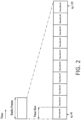
- FIG. 2 is a diagram illustrating a schematic configuration of a radio frame according to the present embodiment.
- the horizontal axis is a time axis.
- the length of each radio frame may be 10 ms.
- the radio frame may include 10 time slots.
- the length of each time slot may be 1 ms.
- FIG. 3 is a diagram illustrating a schematic configuration of a time slot according to the present embodiment.
- the configuration of a time slot in one cell is shown.
- the horizontal axis is a time axis
- the vertical axis is a frequency axis.
- the time slot may include N symb OFDM symbols.
- 1 is the OFDM symbol number/index and k is the subcarrier number/index.
- the physical signal or the physical channel transmitted in each of the time slots is represented by a resource grid.
- a resource grid is defined by a plurality of subcarriers and a plurality of OFDM symbols. Each element within a resource grid is referred to as a resource element.
- the resource element is represented by a subcarrier number/index k and an OFDM symbol number/index 1.
- N symb may be 14.
- N symb may be 12.
- N RB is a bandwidth setting, which is represented by a multiple of N RB SC , for a serving cell.
- N RB SC is the size of a resource block (physical resource block), which is represented by the number of subcarriers, in the frequency domain.
- the subcarrier spacing ⁇ f may be 15 kHz.
- the N RB SC may be 12.
- the size of a resource block (physical resource block) in the frequency domain may be 180 kHz.
- One physical resource block is defined by N symb OFDM symbols that are consecutive in the time domain and N RB SC subcarriers that are consecutive in the frequency domain. Therefore, one physical resource block includes (N symb .N RB SC ) resource elements.
- One physical resource block may correspond to one time slot in the time domain.
- the physical resource blocks may be numbered n PRB (0,1,ising, N RB -1) in the ascending order of frequencies in the frequency domain.
- FIG. 4 is a schematic block diagram illustrating a configuration of a terminal apparatus 1 according to the present embodiment.
- the terminal apparatus 1 includes a radio transceiving unit 10 and a higher layer processing unit 14.
- the radio transceiving unit 10 includes an antenna unit 11, an RF (Radio Frequency) unit 12, and a baseband unit 13.
- the higher layer processing unit 14 includes a medium access control layer processing unit 15 and a radio resource control layer processing unit 16.
- the radio transceiving unit 10 is also referred to as a transmitting unit, a receiving unit, an encoding unit, a decoding unit, or a physical layer processing unit.
- the higher layer processing unit 14 outputs uplink data (transport block) generated by a user operation or the like to the radio transceiving unit 10.
- the higher layer processing unit 14 performs processing of a medium access control (MAC) layer, a packet data convergence protocol (PDCP) layer, a radio link control (RLC) layer, and a radio resource control (RRC) layer.
- MAC medium access control
- PDCP packet data convergence protocol
- RLC radio link control
- RRC radio resource control
- the medium access control layer processing unit 15 included in the higher layer processing unit 14 performs the processing of the MAC layer.
- the medium access control layer processing unit 15 controls a random access procedure based on various types of configuration information/parameters managed by the radio resource control layer processing unit 16.
- the radio resource control layer processing unit 16 included in the higher layer processing unit 14 performs processing of the RRC layer.
- the radio resource control layer processing unit 16 manages various types of configuration information/parameters of the terminal apparatus itself.
- the radio resource control layer processing unit 16 sets various types of configuration information/parameters based on a higher layer signal received from the base station apparatus 3. Namely, the radio resource control layer processing unit 16 sets the various types of configuration information/parameters based on information indicating the various types of configuration information/parameters received from the base station apparatus 3.
- the radio transceiving unit 10 performs processing of the physical layer, such as modulation, demodulation, encoding, decoding, and the like.
- the radio transceiving unit 10 demultiplexes, demodulates, and decodes the signal received from the base station apparatus 3, and then outputs decoded information to the higher layer processing unit 14.
- the radio transceiving unit 10 generates a transmission signal by modulating and encoding data, and then transmits the transmission signal to the base station apparatus 3.
- the RF unit 12 converts (down-converts) a signal received via the antenna unit 11 into a baseband signal by quadrature demodulation, and then removes unnecessary frequency components.
- the RF unit 12 outputs a processed analog signal to the baseband unit.
- the baseband unit 13 converts the analog signal input from the RF unit 12 into a digital signal.
- the baseband unit 13 removes a portion corresponding to a cyclic prefix (CP) from the converted digital signal, performs a fast Fourier transform (FFT) on the signal from which the CP has been removed, and extracts a signal in the frequency domain.
- CP cyclic prefix
- FFT fast Fourier transform
- the baseband unit 13 generates an SC-FDMA symbol by performing an inverse fast Fourier transform (IFFT) on data, adds a CP to the generated SC-FDMA symbol, generates a baseband digital signal, and converts the baseband digital signal into an analog signal.
- the baseband unit 13 outputs the converted analog signal to the RF unit 12.
- IFFT inverse fast Fourier transform
- the RF unit 12 removes unnecessary frequency components from the analog signal input from the baseband unit 13 by using a low-pass filter, up-converts the analog signal to a signal with a carrier frequency, and transmits the up-converted signal via the antenna unit 11. Further, the RF unit 12 amplifies power.
- the RF unit 12 may provide a function of controlling transmission power.
- the RF unit 12 may also be referred to as a transmission power control unit.
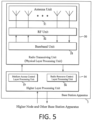
- FIG. 5 is a schematic block diagram illustrating a configuration of a base station apparatus 3 according to the present embodiment.
- the base station apparatus 3 includes a radio transceiving unit 30 and a higher layer processing unit 34.
- the radio transceiving unit 30 includes an antenna unit 31, an RF unit 32, and a baseband unit 33.
- the higher layer processing unit 34 includes a medium access control layer processing unit 35 and a radio resource control layer processing unit 36.
- the radio transceiving unit 30 is also referred to as a transmitting unit, a receiving unit, an encoding unit, a decoding unit, or a physical layer processing unit.
- the higher layer processing unit 34 performs processing of a medium access control (MAC) layer, a packet data convergence protocol (PDCP) layer, a radio link control (RLC) layer, and a radio resource control (RRC) layer.
- MAC medium access control
- PDCP packet data convergence protocol
- RLC radio link control
- RRC radio resource control
- the medium access control layer processing unit 35 included in the higher layer processing unit 34 performs the processing of the MAC layer.
- the medium access control layer processing unit 35 controls a random access procedure based on various types of configuration information/parameters managed by the radio resource control layer processing unit 36.
- the radio resource control layer processing unit 36 included in the higher layer processing unit 34 performs processing of the RRC layer.
- the radio resource control layer processing unit 36 generates, or acquires from a higher node, downlink data (transport block) allocated on a physical downlink shared channel, system information, an RRC message, a MAC control element (CE), and the like, and outputs them to the radio transceiving unit 30.
- the radio resource control layer processing unit 36 manages various types of configuration information/parameters for each terminal apparatus 1.
- the radio resource control layer processing unit 36 can set various types of configuration information/parameters for each terminal apparatus 1 via a higher layer signal. That is, the radio resource control layer processing unit 36 transmits/broadcasts information indicating various types of configuration information/parameters.
- the functionality of the radio transceiving unit 30 is similar to the functionality of the radio transceiving unit 10, and hence the description thereof is omitted.
- Each of the units with reference numerals 10 to 16 included in the terminal apparatus 1 may be configured as a circuit.
- Each of the units with reference numerals 30 to 36 included in the base station apparatus 3 may be configured as a circuit.
- Each of the units with reference numerals 10 to 16 included in the terminal apparatus 1 may be configured as at least one processor and a memory connected to the at least one processor.
- Each of the units with reference numerals 30 to 36 included in the base station apparatus 3 may be configured as at least one processor and a memory connected to the at least one processor.
- BWP band width part
- the BWP is defined by one or more physical resource blocks that are contiguous in the frequency domain.
- One or more downlink BWPs and one or more uplink BWPs may be configured for a serving cell.
- the one or more downlink BWPs include at least one initial downlink BWP.
- the one or more uplink BWPs include at least one initial uplink BWP.
- the index of the initial downlink BWP and the index of the initial uplink BWP are 0.
- the terminal apparatus 1 may receive a higher layer parameter indicating the initial downlink BWP.
- At most one downlink BWP of one or more downlink BWPs is activated simultaneously.
- at most one uplink BWP of one or more uplink BWPs is activated simultaneously.
- the terminal apparatus 1 may switch an activated downlink BWP and/or an activated uplink BWP based on an RRC parameter and/or a PDCCH. Switching an activated BWP in the uplink and downlink means activating a deactivated BWP and deactivating an activated BWP simultaneously.
- the terminal apparatus 1 may monitor a PDCCH and receive a PDSCH (DL-SCH) in an activated downlink BWP.
- the terminal apparatus 1 may not monitor the PDCCH and receive the PDSCH (DL-SCH) in a deactivated downlink BWP.
- the monitoring may mean to attempt to decode the PDCCH according to a DCI format.
- the terminal apparatus 1 may transmit a PUSCH (UL-SCH), a PUCCH, and an SRS in an activated uplink BWP.
- the terminal apparatus 1 may not transmit a PUSCH (UL-SCH), a PUCCH, and an SRS in a deactivated uplink BWP.
- An activated downlink BWP is also referred to as an active downlink BWP.
- An activated uplink BWP is also referred to as an active uplink BWP.
- the CORESET (control resource set) will be described.
- the CORESET according to the present embodiment is included in an activated downlink BWP.
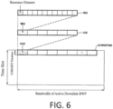
- FIG. 6 is a diagram illustrating an example of a CORESET according to the present embodiment.
- the CORESET is included in one BWP.
- a duration of CORESET in one PDCCH monitoring occasion is one, two or three OFDM symbols.
- the PDCCH monitoring occasion is a set of OFDM symbols in which CORESET monitoring is configured.
- the CORESET may include a plurality of CCEs (Control Channel Elements).
- the CORESET may include a plurality of resource elements that are contiguous in the frequency domain.
- a CCE may include 6 contiguous REGs (Resource Element Groups) in the frequency domain.
- One REG may include 12 resource elements that are contiguous in the frequency domain.
- FIG. 7 is a diagram illustrating an example of a search space according to the present embodiment.
- the search space is a set of PDCCH candidates.
- the PDCCH is transmitted in the PDCCH candidate.
- the terminal apparatus 1 attempts to decode the PDCCH in the search space.
- the PDCCH candidate may include one or more CCEs.
- the number of CCEs that constitute the PDCCH candidate is also referred to as an aggregation level.
- the search space 700 is a CSS (Common Search Space).
- the search space 710 is a USS (UE-Specific Search Space).
- the CSS 700 and the USS 710 are included in one CORESET.
- the PDCCH candidates included in the USS 710 may be given at least based on a predetermined RNTI.
- the predetermined RNTI may be a C-RNTI (Cell Radio Network Temporary Identifier).
- the PDCCH candidates included in the CSS 700 may be given regardless of the predetermined RNTI.
- the CSS 700 includes two PDCCH candidates 701, 702 with each having an aggregation level of 8.
- the USS 710 includes one PDCCH candidate 711 having an aggregation level of 16, and three PDCCH candidates 712, 713, 714 with each having an aggregation level of 8.
- the set of CCEs constituting the PDCCH candidate 701 is the same as the set of CCEs constituting the PDCCH candidate 712.
- the set of CCEs constituting the PDCCH candidate 702 is different from the set of CCEs constituting the PDCCH candidate 711, but the CCE with the smallest index that constitutes the PDCCH candidate 702 is the same as the CCE with the smallest index that constitutes the PDCCH candidate 711.
- the size of a DCI format is also referred to as a DCI size or the payload size of a DCI format.
- the DCI format 0_0 may be used for scheduling of a PUSCH within a single cell.
- the DCI format 0_0 of the present embodiment is DCI format 0_0 with CRC scrambled by C-RNTI.
- the DCI format 0_0 includes at least the following fields.
- the size N FDRA0_0 of the "frequency domain resource assignment" field of DCI format 0_0 may be given by the following formula (1).
- the size of the "UL/SUL indicator” field may be given at least based on a higher layer parameter.
- the size of the "UL/SUL indicator” field is 0 bit.
- the size of the fields of DCI format 0_0 other than the size of the "frequency domain resource assignment" field and the size of the "UL/SUL indicator” field is predefined by the specification.
- N FDRA 0 _ 0 ceil log 2 N UL , BWP N UL , BWP + 1 / 2
- N UL, BWP is represented by the number of resource blocks.
- N UL, BWP is the size of an initial uplink BWP or the size of an active uplink BWP.
- N UL, BWP may be the size of the active uplink BWP in a case that DCI format 0_0 is monitored in the USS and that the condition A and the condition B are satisfied. Otherwise, N UL, BWP may be the size of the initial uplink BWP.
- N UL, BWP may be the size of the initial uplink BWP in a case that the condition A or the condition B is not satisfied or in a case that DCI format 0_0 is monitored in the CSS. Otherwise, N UL, BWP may be the size of the active uplink BWP.
- the condition A may be a condition that the total number of different DCI sizes monitored per slot is no more than X A (e.g. 4) for the cell.
- X A e.g. 4
- the value of X A may be 4 or a value greater than 4.
- the condition B may be a condition that the total number of different DCI sizes with C-RNTI monitored per slot is no more than X B (e.g. 3) for the cell.
- X B e.g. 3
- the value of X B may be 3 or a value greater than 3.
- the value of X B may be the same as or smaller than the value of X A .
- the DCI format 1_0 may be used for scheduling of a PDSCH within a single cell in a case that the "frequency domain resource assignment" field of the DCI format 1_0 is not set to all "1"s.
- the "frequency domain resource assignment" field of the DCI format 1_0 of the present embodiment is not set to all "1 "s. That is, the DCI format 1_0 of the present embodiment may be used for scheduling of a PDSCH in a single cell.
- the DCI format 1_0 of the present embodiment is DCI format 0_0 with a CRC scrambled by C-RNTI.
- the DCI format 1_0 includes the following fields.
- N FDRA1_0 of the "frequency domain resource assignment" field of DCI format 1_0 may be given by the following formula (2).
- the size of the fields of DCI format 1_0 other than the size of the "frequency domain resource assignment" field is predefined by the specification.
- N FDRAI _ 0 ceil log 2 N DL , BWP N DL , BWP + 1 / 2
- N DL, BWP is represented by the number of resource blocks.
- N DL, BWP is the size of an active downlink BWP or the size of a predetermined band X.
- the predetermined band X may be an initial downlink BWP or a predetermined CORESET.
- the predetermined CORESET may be a CORESET for monitoring DCI format 1_0 or a CORESET with a predetermined index.
- the predetermined index may be a predetermined value (e.g., 0).
- the predetermined index may be given by an RRC parameter.
- the band of the initial downlink BWP may be different from that of the predetermined CORESET.
- N DL, BWP may be the size of the active downlink BWP in a case that DCI format 1_0 is monitored in the USS and the condition A and the condition B are satisfied. Otherwise, N UL, BWP may be the size of the predetermined band X.
- N DL, BWP may be the size of the predetermined band X in a case that the condition A or the condition B is not satisfied or in a case that DCI format 0_0 is monitored in the CSS. Otherwise, N DL, BWP may be the size of the active downlink BWP.
- the size of the DCI format 0_0 monitored in the CSS for scheduling a serving cell is the same as that of the DCI format 1_0 monitored in the CSS for scheduling the same serving cell.
- one or more bits may be appended in the DCI format 0_0 until the size of the DCI format 0_0 is the same as the size of the DCI format 1_0.
- the one or more bits are set to 0.
- the bit width of the "frequency domain resource assignment" field may be reduced by truncating the first one or more MSBs (Most Significant Bits) of the "frequency domain resource assignment" field, so as to make the size of the DCI format 0_0 the same as the size of the DCI format 1_0.
- the size of the DCI format 0_0 monitored in the USS for scheduling a serving cell is the same as that of the DCI format 1_0 monitored in the USS for scheduling the same serving cell.
- one or more bits may be appended in the DCI format 0_0 until the size of the DCI format 0_0 is the same as the size of the DCI format 1_0.
- the one or more bits are set to 0.
- the bit width of the "frequency domain resource assignment" field may be reduced by truncating the first one or more MSBs (Most Significant Bits) of the "frequency domain resource assignment" field, so as to make the size of the DCI format 0_0 the same as the size of the DCI format 1_0.
- one or more bits may be appended in the DCI format 0_0 until the size of the DCI format 0_0 is the same as the size of the DCI format 1_0.
- the one or more bits are set to 0.
- the size of the DCI format 0_0 is the same as the number of information bits in the DCI format 0_0 prior to a padding or truncating process.
- one or more bits may be appended in the DCI format 1_0 until the size of the DCI format 1_0 is the same as the size of the DCI format 0_0.
- the one or more bits are set to 0.
- the terminal apparatus 1 may identify the DCI format 0_0 and the DCI format 1_0 through the "Identifier for DCI formats" field.
- the "Identifier for DCI formats” field of the DCI format 0_0 is set to 0.
- the “Identifier for DCI formats” field of the DCI format 1_0 is set to 1.
- the DCI format 0_1 may be used for scheduling of a PUSCH within a single cell. Unless otherwise specified, the DCI format 0_1 of the present embodiment is DCI format 0_1 with CRC scrambled by C-RNTI. The set of fields included in the DCI format 0_1 is different from the set of fields included in DCI format 0_0.
- the DCI format 1_1 may be used for scheduling of a PDSCH within a single cell. Unless otherwise specified, the DCI format 1_1 of the present embodiment is DCI format 1_1 with CRC scrambled by C-RNTI. The set of fields included in the DCI format 1_1 is different from the set of fields included in DCI format 1_0.
- the DCI format 0_1 and DCI format 1_1 are monitored only in the USS of the CSS and USS.
- the DCI format 0_1 and DCI format 1_1 are not monitored in the CSS.
- the size of the DCI format 0_1 for scheduling a serving cell is different from any one of the following: the size of the DCI format 0_0 monitored in the CSS for scheduling the same serving cell, the size of the DCI format 1_0 monitored in the CSS for scheduling the same serving cell, the size of the DCI format 0_0 monitored in the USS for scheduling the same serving cell, and the size of the DCI format 1_0 monitored in the USS for scheduling the same serving cell.
- one or more bits may be appended to the DCI format 0_1 until the size of the DCI format 0_1 is different from any one of the following: the size of the DCI format 0_0 monitored in the CSS for scheduling the same serving cell, the size of the DCI format 1_0 monitored in the CSS for scheduling the same serving cell, the size of DCI format 0_0 monitored in the USS for scheduling the same serving cell, and the size of DCI format 1_0 monitored in the USS for scheduling the same serving cell.
- the one or more bits may be appended to the DCI format 0_1 until the size of the DCI format 0_1 is different from any one of the following: the size of the DCI format 0_0 monitored in the CSS for scheduling the same serving cell, the size of the DCI format 1_0 monitored in the CSS for scheduling the same serving cell, the size of DCI format 0_0 monitored in the USS for scheduling the same serving cell, and the size of DCI format 1_0 monitored in the USS for scheduling the same serving cell.
- one or more bits may be appended to the DCI format 0_1 until the size of the DCI format 0_1 is different from any one of the size of the DCI format 0_0 monitored in the CSS for scheduling the same serving cell and the size of the DCI format 0_0 monitored in the USS for scheduling the same serving cell.
- the one or more bits are set to 0.
- one or more bits may be appended to the DCI format 0_1 until the size of the DCI format 0_1 is different from any one of the size of the DCI format 1_0 monitored in the CSS for scheduling the same serving cell and the size of the DCI format 1_0 monitored in the USS for scheduling the same serving cell.
- the one or more bits are set to 0.
- one or more bits may be appended to the DCI format 0_1 until the size of the DCI format 0_1 is different from any one of the following: the size of the DCI format 0_0 derived according to the size of the initial uplink BWP for scheduling the same serving cell, the size of the DCI format 1_0 derived according to the predetermined band X for scheduling the same serving cell
- one or more bits may be appended to the DCI format 0_1 until the size of the DCI format 0_1 is different from any one of the size of the DCI format 0_0 derived according to the initial uplink BWP for scheduling the same serving cell and the size of the DCI format 0_0 derived according to the size of the active uplink BWP for scheduling the same serving cell.
- the one or more bits are set to 0.
- one or more bits may be appended to the DCI format 0_1 until the size of the DCI format 0_1 is different from any one of the size of the DCI format 1_0 derived according to the predetermined band X for scheduling the same serving cell and the size of the DCI format 1_0 derived according to the size of the active downlink BWP for scheduling the same serving cell.
- the one or more bits are set to 0.
- one or more bits may be appended to the DCI format 0_1 until the size of the DCI format 1_1 is different from any one of the following: the size of the DCI format 1_0 derived according to the size of the initial downlink BWP for scheduling the same serving cell, the size of the DCI format 1_0 derived according to the above-mentioned predetermined CORESET for scheduling the same serving cell, and the size of DCI format 1_0 derived according to the size of an active downlink BWP for scheduling the same serving cell, one or more bits may be appended to the DCI format 0_1 until the size of the DCI format 1_1 is different from any one of the following: the size of the DCI format 1_0 derived according to the size of the initial downlink BWP for scheduling the same serving cell, the size of the DCI format 1_0 derived according to the above-mentioned predetermined CORESET for scheduling the same serving cell, and the size of DCI format 1_0 derived according to the size of the active downlink
- the size of the DCI format 1_1 for scheduling a serving cell is different from any one of the following: the size of the DCI format 0_0 monitored in the CSS for scheduling the same serving cell, the size of the DCI format 1_0 monitored in the CSS for scheduling the same serving cell, the size of the DCI format 0_0 monitored in the USS for scheduling the same serving cell, and the size of the DCI format 1_0 monitored in the USS for scheduling the same serving cell.
- one or more bits may be appended to the DCI format 1_1 until the size of the DCI format 1_1 is different from any one of the following: the size of the DCI format 0_0 monitored in the CSS for scheduling the same serving cell, the size of the DCI format 1_0 monitored in the CSS for scheduling the same serving cell, the size of DCI format 0_0 monitored in the USS for scheduling the same serving cell, and the size of DCI format 1_0 monitored in the USS for scheduling the same serving cell.
- the one or more bits are
- one or more bits may be appended to the DCI format 1_1 until the size of the DCI format 1_1 is different from any one of the size of the DCI format 0_0 monitored in the CSS for scheduling the same serving cell and the size of the DCI format 0_0 monitored in the USS for scheduling the same serving cell.
- the one or more bits are set to 0.
- one or more bits may be appended to the DCI format 1_1 until the size of the DCI format 1_1 is different from any one of the size of the DCI format 1_0 monitored in the CSS for scheduling the same serving cell and the size of the DCI format 1_0 monitored in the USS for scheduling the same serving cell.
- the one or more bits are set to 0.
- one or more bits may be appended to the DCI format 1_1 until the size of the DCI format 1_1 is different from any one of the following: the size of the DCI format 0_0 derived according to the size of the initial uplink BWP for scheduling the same serving cell, the size of the DCI format 1_0 derived according to the predetermined band X for scheduling the same serving cell, the
- one or more bits may be appended to the DCI format 1_1 until the size of the DCI format 1_1 is different from any one of the size of the DCI format 0_0 derived according to the initial uplink BWP for scheduling the same serving cell and the size of the DCI format 0_0 derived according to the size of the active uplink BWP for scheduling the same serving cell.
- the one or more bits are set to 0.
- one or more bits may be appended to the DCI format 1_1 until the size of the DCI format 1_1 is different from any one of the size of the DCI format 1_0 derived according to the predetermined band X for scheduling the same serving cell and the size of the DCI format 1_0 derived according to the size of the active downlink BWP for scheduling the same serving cell.
- the one or more bits are set to 0.
- one or more bits may be appended to the DCI format 1_1 until the size of the DCI format 1_1 is different from any one of the following: the size of the DCI format 1_0 derived according to the size of the initial downlink BWP for scheduling the same serving cell, the size of the DCI format 1_0 derived according to the above-mentioned predetermined CORESET for scheduling the same serving cell, and the size of DCI format 1_0 derived according to the size of an active downlink BWP for scheduling the same serving cell, one or more bits may be appended to the DCI format 1_1 until the size of the DCI format 1_1 is different from any one of the following: the size of the DCI format 1_0 derived according to the size of the initial downlink BWP for scheduling the same serving cell, the size of the DCI format 1_0 derived according to the above-mentioned predetermined CORESET for scheduling the same serving cell, and the size of DCI format 1_0 derived according to the size of the active downlink BW
- the size of the DCI format 0_1 for scheduling a serving cell may be the same or different from the size of the DCI format 1_1 for scheduling the same serving cell.
- the terminal apparatus 1 may identify the DCI format 0_1 and the DCI format 1_1 by through the "Identifier for DCI formats" field.
- the “Identifier for DCI formats” field of the DCI format 0_1 is set to 0.
- the “Identifier for DCI formats” field of the DCI format 1_0 is set to 1.
- FIG. 8 is a diagram illustrating the correspondence between a frequency domain resource assignment field and N DL, BWP , N UL, BWP according to the present embodiment. For example, when a predetermined size X is 6, the number of bits of the "frequency domain resource assignment" field derived from the predetermined size X is 5.
- FIG. 9 is a diagram illustrating an example of DCI format 0_0 and DCI format 1_0 according to the present embodiment.
- the numeral 900 denotes a DCI format 1_0 derived from the size of a predetermined band X.
- the numeral 901 denotes a DCI format 1_0 derived from the size of an active downlink BWP.
- the numeral 902 denotes a DCI format 0_0 derived from the size of an initial uplink BWP.
- the numeral 903 denotes a DCI format 0_0 derived from the size of an active uplink BWP.
- the size of the "frequency domain resource assignment" field of the DCI format 1_0 900, the size of the "frequency domain resource assignment” field of the DCI format 1_0 901, and the size of the "frequency domain resource assignment” field of the DCI format 0_0 903 are all 13 bits.
- the size of the "frequency domain resource assignment" field of the DCI format 0_0 902 is 11 bits.
- the DCI format 900 is the same as the DCI format 901, and the set of fields of the DCI format 900 is the same as the set of fields of the DCI format 901.
- the DCI format 902 is the same as the DCI format 903, and the set of fields of the DCI format 902 is different from the set of fields of the DCI format 903.
- the number of bits of the "frequency domain resource assignment" field derived from the size of the initial uplink BWP may be the same as the number of bits of the "frequency domain resource assignment” field derived from the size of the active uplink BWP. That is, even in a case that the size of the initial uplink BWP and the size of the active uplink BWP are different, the set of fields of DCI format 0_0 derived from the size of the initial uplink BWP may be the same as the set of fields of DCI format 0_0 derived from the size of the active uplink BWP.
- the number of bits of the "frequency domain resource assignment" field derived from the size of the initial uplink BWP may be the same as the number of bits of the "frequency domain resource assignment" field derived from the size of the active uplink BWP.
- the number of bits of the "frequency domain resource assignment" field derived from the size of the predetermined band X may be the same as the number of bits of the "frequency domain resource assignment” field derived from the size of the active downlink BWP. That is, even in a case that the size of the predetermined band X and the size of the active downlink BWP are different, the set of fields of DCI format 1_0 derived from the size of the predetermined band X may be the same as the set of fields of DCI format 1_0 derived from the size of the active downlink BWP.
- the number of bits of the "frequency domain resource assignment" field derived from the size of the predetermined band X may be the same as the number of bits of the "frequency domain resource assignment" field derived from the size of the active downlink BWP.
- DCI format 2_0 is used for notifying a slot format.
- the size of the DCI format 2_0 is configured by a higher layer parameter.
- the DCI format 2_0 of the present embodiment is DCI format 2_0 with CRC scrambled by SFI-RNTI.
- the size of DCI format 2_0 may be the same as or different from the size of other DCI format.
- the terminal apparatus 1 may identify the DCI format 2_0 through the SFI-RNTI.
- the DCI format 2_1 is used for notifying the physical resource block(s) and OFDM symbol(s) where the terminal apparatus 1 may assume no transmission is intended for the terminal apparatus 1.
- the size of the DCI format 2_1 is configured by a higher layer parameter.
- the DCI format 2_1 of the present embodiment is DCI format 2_1 with the CRC scrambled by the INT-RNTI.
- the size of DCI format 2_1 may be the same as or different from the size of other DCI format.
- the terminal apparatus 1 may identify the DCI format 2_1 through the INT-RNTI.
- the "frequency domain resource assignment" field of the DCI format 0_0 includes RIV (Resource Indication Value).
- the RIV included in the "frequency domain resource assignment" field of the DCI format 0_0 is also referred to as RIV 0_0.
- the calculation for the RIV 0_0 in the base station apparatus 3 is performed based on the type of the search space (CSS or USS) in which the DCI format 0_0 is transmitted.
- the interpretation for the RIV 0_0 in the terminal apparatus 1 is performed based on the type of the search space (CSS or USS) in which the DCI format 0_0 is transmitted.
- the RIV 0_0 may indicate resource block allocation information.
- the resource block allocation information of the RIV 0_0 indicates a set of continuously allocated VRBs (Virtual Resource Blocks) within an active uplink BWP to the scheduled terminal apparatus 1.
- a VRB within the active uplink BWP is mapped to a physical resource block within the same active uplink BWP.
- the RIV 0_0 may be given based on at least RB UL_start and L UL_RBs .
- RB UL_start is a starting resource block of the set of continuously allocated VRBs.
- L UL_RBs is the length (the number of resource blocks) of the set of continuously allocated VRBs.
- indexing of the resource blocks is determined within the active uplink BWP. That is, the indexing (numbering) of the resource blocks associated with the RIV 0_0, RB UL_start , and L UL_RBs starts from the lowest resource block within the active uplink BWP.
- the lowest resource block may be a resource block with the lowest frequency.
- the lowest resource block may be the resource block with the smallest index of common resource blocks.
- FIG. 10 is a diagram illustrating a pseudo code for calculating RIV 0_0 according to the present embodiment.
- the RIV 0_0 may be given by using N UL_ BWP size based on the pseudo-code of FIG. 10 except for a case where the size of the DCI format 0_0 in the USS is derived from the size of an initial uplink BWP, and where the DCI format 0_0 is applied to an active uplink BWP different from the initial uplink BWP.
- the terminal apparatus 1 may acquire RB UL_ start and L UL_RBs based on the RIV 0_0 and N UL_BWP size except for the case where the size of the DCI format 0_0 in the USS is derived from the size of an initial uplink BWP, and where the DCI format 0_0 is applied to an active uplink BWP different from the initial uplink BWP.
- N UL_BWP size is the size of the active uplink BWP except for a case where the DCI format 0_0 is decoded in the CSS.
- N UL_BWP size is the size of the active uplink BWP in a case where the DCI format 0_0 is decoded in the USS.
- N UL_BWP size is the size of the initial uplink BWP in a case where the DCI format 0_0 is decoded in the CSS.
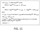
- FIG. 11 is a diagram illustrating a pseudo code for calculating RIV 0_0 according to the present embodiment.
- the RIV 0_0 may be given by using N UL_BWP initial and N UL_BWP active based on the pseudo-code of FIG. 11 in a case where the size of the DCI format 0_0 in the USS is derived from the size of an initial uplink BWP, and where the DCI format 0_0 is applied to an active uplink BWP different from the initial uplink BWP.
- the terminal apparatus 1 may acquire RB UL_start and L UL_RBs based on the RIV 0_0, N UL_BWP initial and N UL_BWP active in the case where the size of the DCI format 0_0 in the USS is derived from the size of an initial uplink BWP, and where the DCI format 0_0 is applied to an active uplink BWP different from the initial uplink BWP.
- N UL_BWP initial is the size of the initial uplink BWP.
- N UL_BWP active is the size of the active uplink BWP.
- the "frequency domain resource assignment" field of the DCI format 1_0 includes RIV (Resource Indication Value).
- the RIV included in the "frequency domain resource assignment" field of the DCI format 1_0 is also referred to as RIV 1_0.
- the calculation for the RIV 1_0 in the base station apparatus 3 is performed based on the type of the search space (CSS or USS) in which the DCI format 1_0 is transmitted.
- the interpretation for the RIV 1_0 in the terminal apparatus 1 is performed based on the type of the search space (CSS or USS) in which the DCI format 1_0 is transmitted.
- the RIV 1_0 may indicate resource block allocation information.
- the resource block allocation information of the RIV 1_0 indicates a set of continuously allocated VRBs (Virtual Resource Blocks) within an active downlink BWP to the scheduled terminal apparatus 1.
- a VRB within the active downlink BWP is mapped to a physical resource block within the same active downlink BWP.
- the RIV 1_0 may be given based on at least RB DL_start and L DL_RBs .
- RB DL_start is a starting resource block of the set of continuously allocated VRBs.
- L DL_RBs is the length (the number of resource blocks) of the set of continuously allocated VRBs.
- indexing (numbering) of the resource blocks may start from the lowest resource block of a CORESET that receives the DCI format 1_0, regardless of which downlink BWP is the active downlink BWP.
- the lowest resource block may be a resource block with the lowest frequency.
- the lowest resource block may be the resource block with the smallest index of common resource blocks.
- the indexing of the resource blocks may be determined within the active downlink BWP. That is, the indexing (numbering) of the resource blocks associated with the RIV 1_0, RB DL_start , and L DL_RBs may start from the lowest resource block within the active downlink BWP.
- a DCI format other than the DCI format 1_0 in the CSS may be DCI format 1_0 in the USS.
- indexing (numbering) of the resource blocks may start from the lowest resource block of a CORESET that receives the DCI format 1_0; and for a PDSCH scheduled by using DCI format 1_0 with C-RNTI, indexing of the resource blocks may be determined within the active downlink BWP.
- the DCI format 1_0 with SI-RNTI and the DCI format 1_0 with C-RNTI may be transmitted and/or received in the CSS.
- FIG. 12 is a diagram illustrating a pseudo code for calculating RIV 1_0 according to the present embodiment.
- the RIV 1_0 may be given by using N DL_BWP size based on the pseudo-code of FIG. 12 except for a case where the size of the DCI format 1_0 in the USS is derived from the size of a predetermined band X, and where the DCI format 1_0 is applied to an active downlink BWP different from the predetermined band X.
- the terminal apparatus 1 may acquire RB DL_start and L DL_RBs based on the RIV 1_0 and N DL_ BWP size except for the case where the size of the DCI format 1_0 in the USS is derived from the size of a predetermined band X, and where the DCI format 1_0 is applied to an active downlink BWP different from the predetermined band X.
- N DL_BWP size is the size of the active downlink BWP except for a case where the DCI format 1_0 is decoded in the CSS.
- N DL_BWP size is the size of the active downlink BWP in a case where the DCI format 1_0 is decoded in the USS.
- N DL_BWP size is the size of the predetermined band X in a case where the DCI format 1_0 is decoded in the CSS.
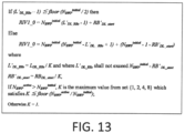
- FIG. 13 is a diagram illustrating a pseudo code for calculating RIV 1_0 according to the present embodiment.
- the RIV 1_0 may be given by using N DL_BWP initial and N DL_BWP actlve based on the pseudo-code of FIG. 13 in a case where the size of the DCI format 1_0 in the USS is derived from the size of a predetermined band X, and where the DCI format 1_0 is applied to an active downlink BWP different from the predetermined band X.
- the terminal apparatus 1 may acquire RB UL_start and L UL_RBs based on the RIV 1_0, N DL_BWP initial and N DL_BWP active in the case where the size of the DCI format 1_0 in the USS is derived from the size of a predetermined band X, and where the DCI format 1_0 is applied to an active downlink BWP different from the predetermined band X.
- N DL_BWP initial is the size of the predetermined frequency band X.
- N DL_BWP active is the size of the active downlink BWP.
- a scrambling sequence c PDCCH (i) for scrambling a PDCCH may be initialized by using c PDCCH_init .
- c PDCCH_init may be given at least based on n RNTI and n ID .
- c PDCCH_init may be given based on the following formula (3).
- c PDCCH_init n RNTI ⁇ 2 16 + n ID mod 2 31
- n ID may be given by the higher layer parameter PDCCH-DMRS-Scrambling-ID for a PDCCH in the USS. Otherwise (i.e., in a case where the higher layer parameter PDCCH-DMRS-Scrambling-ID is not configured, or for a PDCCH in the CSS), n ID may be given by a physical layer cell identity.
- the higher layer parameter PDCCH-DMRS-Scrambling-ID may be configured for a CORESET.
- the higher layer parameter PDCCH-DMRS-Scrambling-ID may be configured for a serving cell.
- the higher layer parameter PDCCH-DMRS-Scrambling-ID may be configured for the terminal apparatus 1.
- n RNTI is C-RNTI for a PDCCH in the USS. Otherwise (i.e., in a case where the higher layer parameter PDCCH-DMRS-Scrambling-ID is not configured, or for a PDCCH in the CSS), n RNTI is 0. In the present embodiment, C-RNTI is a value different from 0.
- a scrambling sequence c PDCCH (i) for a PDCCH in the USS is different from a scrambling sequence c PDCCH (i) for a PDCCH in the CSS.
- a scrambling sequence c PDCCH (i) for a PDCCH in the USS is the same as a scrambling sequence c PDCCH (i) for a PDCCH in the CSS.
- DMRS demodulation reference signal
- the DMRS sequence for a PDCCH is given by a pseudo-random sequence c DMRS (i).
- the pseudo-random sequence c DMRS (i) may be initialized by using c DMRS_init .
- the c DMRS_init may be given based at least on N ID or the above-mentioned n ID .
- N ID may be given by the higher layer parameter PDCCH-DMRS-Scrambling-ID. Otherwise (i.e., in a case where the higher layer parameter PDCCH-DMRS-Scrambling-ID is not configured), N ID may be given by a physical layer cell identity.
- a scrambling sequence c PDCCH (i) for a PDCCH in the USS is the same as a scrambling sequence c PDCCH (i) for a PDCCH in the CSS regardless of which of N ID and n ID the c DMRS_init is given.
- the terminal apparatus 1 may switch the processing according to which of the CSS and the USS is used for receiving the PDCCH, but when a condition C is satisfied, there may be a problem that the terminal apparatus 1 may not correctly determine which of the PDCCH candidates of the CSS and the PDCCH candidates of the USS are used for transmitting the PDCCH.
- the condition C includes at least some or all of the following conditions C1, C2, C3, and C4.
- the condition C1 may be that the terminal apparatus 1 is configured to monitor PDCCH candidates in the CSS and PDCCH candidates in the USS according to the DCI format 0_0/1_0 with C-RNTI in one PDCCH monitoring occasion in one CORESET.
- the condition C1 may be that the terminal apparatus 1 is configured to monitor PDCCH candidates in the CSS and PDCCH candidates in the USS according to the DCI format 0_0/1_0 with C-RNTI in one CORESET.
- the condition C1 may be that the terminal apparatus 1 is configured to monitor PDCCH candidates in the CSS and PDCCH candidates in the USS according to the DCI format 0_0/1_0 with C-RNTI.
- the condition C2 may be that a set of resource elements constituting a PDCCH candidate in the CSS is the same as a set of resource elements constituting a PDCCH candidates in the USS.
- the set of resource elements may be a set of REGs or a set of CCEs.
- the set of resource elements/REGs/CCEs constituting the PDCCH candidate 701 of the CSS 700 is the same as the set of resource elements/REGs/CCEs constituting the PDCCH candidate 712 of the USSD 710.
- the condition C3 may be that the higher layer parameter PDCCH-DMRS-Scrambling-ID is not configured for the terminal apparatus 1.
- the condition C3 may also be that the higher layer parameter PDCCH-DMRS-Scrambling-ID is not configured for a CORESET.
- the condition C3 may also be that a DMRS corresponding to a PDCCH candidate of the CSS is the same as a DMRS corresponding to a PDCCH candidate of the USS, and a PDCCH scrambling sequence corresponding to a PDCCH candidate of the CSS is the same as a PDCCH scrambling sequence corresponding to a PDCCH candidate of the USS.
- the condition C3 may be that a PDCCH scrambling sequence corresponding to a PDCCH candidate of the CSS is the same as a PDCCH scrambling sequence corresponding to a PDCCH candidate of the USS.
- the condition C4 may be that the size of DCI format 0_0/1_0 corresponding to a PDCCH candidate in the CSS is the same as the size of DCI format 0_0/1_0 corresponding to a PDCCH candidate in the USS.
- a set of fields of DCI format 0_0 corresponding to a PDCCH candidate in the CSS may be the same as or different from a set of fields of DCI format 0_0 corresponding to a PDCCH candidate in the USS.
- a set of fields of DCI format 1_0 corresponding to a PDCCH candidate in the CSS may be the same as or different from a set of fields of DCI format 1_0 corresponding to a PDCCH candidate in the USS.
- the PDCCH candidates in the CSS and the PDCCH candidates in the USS may correspond to the same CORESET.
- the DCI format 0_0/1_0 may indicate (1) DCI format 0_0, (2) DCI format 1_0, or (3) DCI format 0_0 and DCI format 1_0.
- the terminal apparatus 1 may perform any one of the following processes D1 to D4 for the PDCCH candidate of the CSS and the PDCCH candidate of the USS under the condition C. That is, the terminal apparatus 1 may determine whether to perform any one of the following processes D1 to D4 based on whether the condition C is satisfied.
- Process D1 The terminal apparatus 1 regards that the PDCCH with the DCI format 0_0/1_0 is transmitted only in the PDCCH candidates of the CSS among the PDCCH candidates of the CSS and the PDCCH candidates of the USS.
- the terminal apparatus 1 may not need to monitor the PDCCH with the DCI format 0_0/1_0 in the PDCCH candidates of the USS.
- the terminal apparatus 1 regards that the PDCCH with the DCI format 0_0/1_0 is transmitted only in the PDCCH candidates of the USS among the PDCCH candidates of the CSS and the PDCCH candidates of the USS.
- the terminal apparatus 1 may not need to monitor the PDCCH with the DCI format 0_0/1_0 in the PDCCH candidates of the CSS.
- the terminal apparatus 1 regards that the PDCCH with the DCI format 0_0/1_0 is transmitted or received in the PDCCH candidates of the USS rather than in the PDCCH candidates of the CSS when it detects the PDCCH with the DCI format 0_0/1_0 in the PDCCH candidates of the CSS.
- the terminal apparatus 1 regards that the PDCCH with the DCI format 0_0/1_0 is transmitted or received in the PDCCH candidates of the CSS rather than in the PDCCH candidates of the USS when it detects the PDCCH with the DCI format 0_0/1_0 in the PDCCH candidates of the USS.
- the terminal apparatus 1 regards that the PDCCH with the DCI format 0_0/1_0 may be transmitted in any PDCCH candidate of the PDCCH candidates of the CSS and the PDCCH candidates of the USS. If the condition C is not satisfied, the terminal apparatus 1 may monitor both of the PDCCH candidates of the CSS and the PDCCH candidates of the USS.
- the base station apparatus 3 may perform any one of the following processes E1 to E4 for the PDCCH candidate of the CSS and the PDCCH candidate of the USS under the condition C. That is, the base station apparatus 3 may determine whether to perform any one of the following processes E1 to E4 based on whether the condition C is satisfied.
- the base station apparatus 3 transmits the PDCCH with the DCI format 0_0/1_0 only in the PDCCH candidates of the CSS among the PDCCH candidates of the CSS and the PDCCH candidates of the USS.
- the base station apparatus 3 transmits the PDCCH with the DCI format 0_0/1_0 only in the PDCCH candidates of the USS among the PDCCH candidates of the CSS and the PDCCH candidates of the USS.
- the base station apparatus 3 regards that the PDCCH with the DCI format 0_0/1_0 is transmitted in the PDCCH candidates of the USS rather than in the PDCCH candidates of the CSS when it transmits the PDCCH with the DCI format 0_0/1_0 in the PDCCH candidates of the CSS.
- the base station apparatus 3 regards that the PDCCH with the DCI format 0_0/1_0 is transmitted in the PDCCH candidates of the CSS rather than in the PDCCH candidates of the USS when it transmits the PDCCH with the DCI format 0_0/1_0 in the PDCCH candidates of the USS.
- the base station apparatus 3 may transmit the PDCCH with the DCI format 0_0/1_0 in any one of the PDCCH candidates of the CSS and the PDCCH candidates of the USS.
- the terminal apparatus 1 may correctly determine which of the PDCCH candidate of the CSS and the PDCCH candidate of the USS under the condition C has transmitted the PDCCH.
- SI-RNTI System Information-Radio Network Temporary Identifier
- SIB System Information Block
- the terminal apparatus 1 may monitor DCI format 1_0 with SI-RNTI, which is used for scheduling SIB1, in type-0 CSS.
- the terminal apparatus 1 may monitor DCI format 1_0 with SI-RNTI, which is used for scheduling SIBs other than SIB 1, in type-Oa CSS.
- RA-RNTI Random Access-Radio Network Temporary Identifier
- the terminal apparatus 1 may monitor DCI format 1_0 with RA-RNTI in type-1 CSS.
- the first type of CSS may include at least a type-0 CSS, a type-Oa CSS, and/or a type-1 CSS.
- the second type of CSS may include at least a type-0 CSS, a type-Oa CSS, and/or a type-1 CSS.
- Each of the type-0 CSS, the type-Oa CSS, and the type-1 CSS belongs to either the first type of CSS or the second type of CSS.
- the first type of CSS may include a type-0 CSS
- the second type of CSS may include a type-Oa CSS and a type-1 CSS.
- a predetermined band X may be the predetermined CORESET described above. That is, the number of bits of the "frequency domain resource assignment" field of the DCI format 1_0 corresponding to the PDCCH candidate of the first type of CSS may be derived from the predetermined CORESET described above.
- the N DL_BWP size may be set as the above-mentioned COREST for calculating the RIV configured in the "frequency domain resource assignment" field of the DCI format 1_0 corresponding to the PDCCH candidate of the first type of CSS. That is, the RIV configured in the "frequency domain resource assignment" field of the DCI format 1_0 corresponding to the PDCCH candidate of the first type of CSS may be derived from the predetermined CORESET described above.
- a predetermined band X may be an initial downlink BWP. That is, the number of bits of the "frequency domain resource assignment" field of the DCI format 1_0 corresponding to the PDCCH candidate of the second type of CSS may be derived from an initial downlink BWP.
- the N DL_BWP size may be set as an initial downlink BWP for calculating the RIV configured in the "frequency domain resource assignment" field of the DCI format 1_0 corresponding to the PDCCH candidate of the second type of CSS. That is, the RIV configured in the "frequency domain resource assignment" field of the DCI format 1_0 corresponding to the PDCCH candidate of the second type of CSS may be derived from an initial downlink BWP.
- the terminal apparatus 1 may switch the processing according to which type of CSS is used for receiving the PDCCH, but when a condition F is satisfied, there may be a problem that the terminal apparatus 1 may not correctly determine which type of PDCCH candidate is used for transmitting the PDCCH.
- the condition F includes at least some or all of the following conditions F1, F2, F3, and F4.
- the condition F1 may be that the terminal apparatus 1 is configured to monitor PDCCH candidates in the first type of CSS and PDCCH candidates in the second type of CSS according to the DCI format 1_0 with C-RNTI in one PDCCH monitoring occasion in one CORESET.
- the condition F1 may be that the terminal apparatus 1 is configured to monitor PDCCH candidates in the first type of CSS and PDCCH candidates in the second type according to the DCI format 1_0 with C-RNTI in one CORESET.
- the condition F1 may be that the terminal apparatus 1 is configured to monitor PDCCH candidates in the first type of CSS and PDCCH candidates in the second type according to the DCI format 1_0 with C-RNTI.
- the C-RNTI in the condition F1 may be an RNTI other than the C-RNTI (e.g., SI-RNTI or RA-RNTI).
- the condition F2 may be that a set of resource elements constituting a PDCCH candidate in the first type of CSS is the same as a set of resource elements constituting a PDCCH candidates in the second type.
- the set of resource elements may be a set of REGs or a set of CCEs.
- the condition F3 may be that the size of DCI format 1_0 corresponding to a PDCCH candidate in the first type of CSS is the same as the size of DCI format 1_0 corresponding to a PDCCH candidate in the second type.
- a set of fields of DCI format 1_0 corresponding to a PDCCH candidate in the first type of CSS may be the same as or different from a set of fields of DCI format 1_0 corresponding to a PDCCH candidate in the second type of CSS.
- the PDCCH candidates in the first type of CSS and the PDCCH candidates in the second type of CSS may correspond to the same CORESET.
- condition F it does not matter whether the higher layer parameter PDCCH-DMRS-Scrambling-ID may be configured. That is, in the condition F, it does not matter whether the higher layer parameter PDCCH-DMRS-Scrambling-ID may be configured for a CORESET. That is, when it is determined whether the condition F is satisfied, the terminal apparatus 1 does not determine whether the higher layer parameter PDCCH-DMRS-Scrambling-ID is configured.
- the terminal apparatus 1 may perform any one of the following processes G1 to G4 for the PDCCH candidate of the first type of CSS and the PDCCH candidate of the second type of CSS under the condition F. That is, the terminal apparatus 1 may determine whether to perform any one of the following processes G1 to G4 based on whether the condition F is satisfied.
- Process G1 The terminal apparatus 1 regards that the PDCCH with the DCI format 1_0 is transmitted only in the PDCCH candidates of the first type of CSS among the PDCCH candidates of the first type of CSS and the PDCCH candidates of the second type of CSS.
- the terminal apparatus 1 may not need to monitor the PDCCH with the DCI format 1_0 in the PDCCH candidates of the second type of CSS.
- Process G2 The terminal apparatus 1 regards that the PDCCH with the DCI format 1_0 is transmitted only in the PDCCH candidates of the second type among the PDCCH candidates of the first type of CSS and the PDCCH candidates of the second type of CSS.
- the terminal apparatus 1 may not need to monitor the PDCCH with the DCI format 1_0 in the PDCCH candidates of the first type of CSS.
- the terminal apparatus 1 regards that the PDCCH with the DCI format 1_0 is transmitted or received in the PDCCH candidates of the second type of CSS rather than in the PDCCH candidates of the first type of CSS when it detects the PDCCH with the DCI format 1_0 in the PDCCH candidates of the first type of CSS.
- the terminal apparatus 1 regards that the PDCCH with the DCI format 1_0 is transmitted or received in the PDCCH candidates of the first type of CSS rather than in the PDCCH candidates of the second type of CSS when it detects the PDCCH with the DCI format 1_0 in the PDCCH candidates of the second type of CSS.
- the terminal apparatus 1 regards that the PDCCH with the DCI format 1_0 may be transmitted in any PDCCH candidate of the PDCCH candidates of the first type of CSS and the PDCCH candidates of the second type of CSS. If the condition F is not satisfied, the terminal apparatus 1 may monitor both of the PDCCH candidates of the first type of CSS and the PDCCH candidates of the second type of CSS.
- the base station apparatus 3 may perform any one of the following processes H1 to H4 for the PDCCH candidate of the first type of CSS and the PDCCH candidate of the second type of CSS under the condition F. That is, the base station apparatus 3 may determine whether to perform any one of the following processes H1 to H4 based on whether the condition F is satisfied.
- the base station apparatus 3 transmits the PDCCH with the DCI format 1_0 only in the PDCCH candidates of the first type of CSS among the PDCCH candidates of the first type of CSS and the PDCCH candidates of the second type of CSS.
- the base station apparatus 3 transmits the PDCCH with the DCI format 1_0 in the PDCCH candidates of the second type among the PDCCH candidates of the first type of CSS and the PDCCH candidates of the second type of CSS.
- the base station apparatus 3 regards that the PDCCH with the DCI format 1_0 is transmitted in the PDCCH candidates of the second type of CSS rather than in the PDCCH candidates of the first type of CSS when it transmits the PDCCH with the DCI format 1_0 in the PDCCH candidates of the first type of CSS.
- the base station apparatus 3 regards that the PDCCH with the DCI format 1_0 is transmitted in the PDCCH candidates of the first type of CSS rather than in the PDCCH candidates of the second type of CSS when it transmits the PDCCH with the DCI format 1_0 in the PDCCH candidates of the second type of CSS.
- the base station apparatus 3 may transmit the PDCCH with the DCI format 1_0 in any one of the PDCCH candidates of the first type of CSS and the PDCCH candidates of the second type of CSS.
- the terminal apparatus 1 may correctly determine which of the PDCCH candidate of the first type of CSS and the PDCCH candidate of the second type of CSS under the condition F has transmitted the PDCCH.
- the CSS of the condition C may be a first type of CSS and/or a second type of CSS.
- the terminal apparatus 1 may perform any one of the processes G1 to G4 after performing the process D1 or the process D3.
- the terminal apparatus 1 and the base station apparatus 3 can communicate efficiently.
- a program running on the base station apparatus 3 and the terminal apparatus 1 according to the present invention may be a program that controls a CPU (Central Processing Unit) and the like to implement the functions of the above-mentioned embodiment according to the present invention (that is, a program that causes a computer to function). Then, the information processed by these apparatuses is temporarily stored in RAM (Random Access Memory) while being processed, then stored in various types of ROM (Read Only Memory) such as a Flash ROM and HDD (Hard Disk Drive), and read, modified or rewritten by the CPU as necessary.
- RAM Random Access Memory
- ROM Read Only Memory
- HDD Hard Disk Drive
- the terminal apparatus 1 and the base station apparatus 3 may be partially achieved by a computer.
- it may be realized by recording a program for realizing the control function on a computer-readable recording medium, and causing a computer system to read the program recorded on the recording medium for execution.
- the "computer system” mentioned here indicates a computer system built into the terminal apparatus 1 or the base station apparatus 3, and the computer system may include an OS and hardware components such as a peripheral apparatus.
- the "computer-readable recording medium” indicates a portable medium such as a flexible disk, a magneto-optical disk, a ROM, a CD-ROM, and the like, and a storage apparatus such as a hard disk built into the computer system.
- the "computer-readable recording medium” may include a recording medium for dynamically storing programs for a short time, such as a communication line in the case of transmitting the programs via a network such as the internet or a communication line such as a telephone line, and may include a recording medium for storing the programs for a fixed period of time, such as a volatile memory within a computer system of a server or a client in such a case.
- the above-mentioned program may be configured to realize some of the functions described above, and also may be configured to be capable of realizing the functions described above in combination with a program already recorded in the computer system.
- the base station apparatus 3 may be implemented as an aggregation (apparatus group) including multiple apparatuses.
- Each of the apparatuses constituting such an apparatus group may include some or all portions of each function or each functional block of the base station apparatus 3 according to the above-mentioned embodiment.
- the apparatus group may be required to have each general function or each functional block of the base station apparatus 3.
- the terminal apparatus 1 according to the above-mentioned embodiment can also communicate with a base station apparatus implemented as aggregation.
- the base station apparatus 3 according to the above-mentioned embodiment may serve as an EUTRAN (Evolved Universal Terrestrial Radio Access Network).
- EUTRAN Evolved Universal Terrestrial Radio Access Network
- the base station apparatus 3 according to the above-mentioned embodiment may have some or all portions of the functions for a node higher than an eNodeB.
- each of the terminal apparatus 1 and the base station apparatus 3 may be implemented as an LSI typically functioning as an integrated circuit or may be implemented as a chip set.
- Each of the functional blocks of the terminal apparatus 1 and the base station apparatus 3 may be individually implemented as a chip, or some or all of the functional blocks of the same may be integrated into a chip.
- a circuit integration technique is not limited to the LSI, and may be implemented with a dedicated circuit or a general-purpose processor.
- a circuit integration technology may appear to replace the LSI technology, and an integrated circuit based on such a technology may also be used.
- the terminal apparatus has been described as an example of a communication apparatus, but the present invention is not limited to such a terminal apparatus, and is applicable to a terminal apparatus or a communication apparatus of a fixed-type or a stationary-type electronic apparatus installed indoors or outdoors, for example, such as an AV apparatus, a kitchen apparatus, a cleaning/washing apparatus, an air-conditioning apparatus, an office apparatus, a vending machine, and other household apparatuses.
- a terminal apparatus has been described as an example of a communication apparatus, but the present invention is not limited to such a terminal apparatus, and is applicable to a terminal apparatus or a communication apparatus of a fixed-type or a stationary-type electronic apparatus installed indoors or outdoors, for example, such as an AV apparatus, a kitchen apparatus, a cleaning/washing apparatus, an air-conditioning apparatus, an office apparatus, a vending machine, and other household apparatuses.
Landscapes
- Engineering & Computer Science (AREA)
- Signal Processing (AREA)
- Computer Networks & Wireless Communication (AREA)
- Databases & Information Systems (AREA)
- Mobile Radio Communication Systems (AREA)
- Radar Systems Or Details Thereof (AREA)
Claims (15)
- Endgerät (1), aufweisend zumindest einen Prozessor und einen mit dem zumindest einen Prozessor gekoppelten Speicher, wobei der Prozessor konfiguriert ist, um:zumindest einen Physical Downlink Control Channel, PDCCH, mit einem Downlink Control Information, DCI, -Format zu empfangen; undeinen Physical Downlink Shared Channel, PDSCH, zu empfangen, der einem Resource Indication Value, RIV, entspricht, der in einem "Frequenzdomänen-Ressourcenzuweisung"-Feld des DCI-Formats konfiguriert ist und der zumindest basierend auf einer Art des Suchraums gegeben ist, in dem der PDCCH detektiert wird;wobei in einem Fall, bei demdas Endgerät konfiguriert ist, einen ersten PDCCH-Kandidaten in einem Common Search Space, CSS, und einen zweiten PDCCH-Kandidaten in einem User Equipment Specific Search Space, USS, gemäß dem DCI-Format mit einen Cell Radio Network Temporary Identifier, C-RNTI, zu überwachen,ein Satz von Control Channel Elements, CCEs, die den ersten PDCCH-Kandidaten darstellen, derselbe ist wie ein Satz von CCEs, die den zweiten PDCCH-Kandidaten darstellen,eine Scrambling-Sequenz für den ersten PDCCH-Kandidaten die gleiche ist wie eine Scrambling-Sequenz für den zweiten PDCCH-Kandidaten, unddie Größe des DCI-Formats, das dem ersten PDCCH-Kandidaten entspricht, dieselbe ist wie die Größe des DCI-Formats, das dem zweiten PDCCH-Kandidaten entspricht,der Prozessor ferner konfiguriert ist, um:
den PDCCH mit dem DCI-Format nur an dem ersten PDCCH-Kandidaten in dem CSS unter dem ersten PDCCH-Kandidaten in dem CSS und dem zweiten PDCCH-Kandidaten in dem USS zu überwachen. - Endgerät nach Anspruch 1, wobei:
ein dem ersten PDCCH-Kandidaten entsprechendes Core Resource Set, CORESET, das gleiche wie ein dem zweiten PDCCH-Kandidaten entsprechendes CORESET ist. - Endgerät nach Anspruch 1, wobei:
ein Satz von Feldern des DCI-Formats entsprechend dem ersten PDCCH-Kandidaten derselbe ist wie ein Satz von Feldern des DCI-Formats entsprechend dem zweiten PDCCH-Kandidaten. - Endgerät nach Anspruch 1, wobei:
das DCI-Format ein DCI-Format 0_0 oder ein DCI-Format 1_0 ist. - Endgerät nach Anspruch 1, wobei:eine Scrambling-Sequenz cPDCCH (i) zum Scrambeln des PDCCH unter Verwendung von cPDCCH_init initialisiert wird,cPDCCH_init zumindest basierend auf nRNTI gegeben ist;in einem Fall, in dem die PDCCH-DMRS-Scrambling-ID des Parameters der höheren Schicht konfiguriert ist, die nRNTI durch C-RNTI für den PDCCH in dem USS gegeben ist, undin einem Fall, in dem die PDCCH-DMRS-Scrambling-ID des Parameters der höheren Schicht nicht konfiguriert ist, die nRNTI 0 ist; undder C-RNTI ein von 0 verschiedener Wert ist.
- Basisstationsvorrichtung (3), die zumindest einen Prozessor und einen mit dem zumindest einen Prozessor gekoppelten Speicher aufweist, wobei der Prozessor konfiguriert ist, um:zumindest einen Physical Downlink Control Channel, PDCCH, mit einem Downlink Control Information, DCI, -Format zu senden; undeinen Physical Downlink Shared Channel, PDSCH, zu senden, der einem Resource Indication Value, RIV, entspricht, der in einem "Frequenzdomänen-Ressourcenzuweisung"-Feld des DCI-Formats konfiguriert ist und der zumindest basierend auf einer Art von Suchraum gegeben ist, in dem der PDCCH detektiert wird;wobei in einem Fall, bei demein Endgerät konfiguriert ist, einen ersten PDCCH-Kandidaten in einem Common Search Space, CSS, und einen zweiten PDCCH-Kandidaten in einem User Equipment Specific Search Space, USS, gemäß dem DCI-Format mit einen Cell Radio Network Temporary Identifier, C-RNTI, zu überwachen,ein Satz von Control Channel Elements, CCEs, die den ersten PDCCH-Kandidaten darstellen, derselbe ist wie ein Satz von CCEs, die den zweiten PDCCH-Kandidaten darstellen,eine Scrambling-Sequenz für den ersten PDCCH-Kandidaten die gleiche ist wie eine Scrambling-Sequenz für den zweiten PDCCH-Kandidaten, unddie Größe des DCI-Formats, das dem ersten PDCCH-Kandidaten entspricht, dieselbe ist wie die Größe des DCI-Formats, das dem zweiten PDCCH-Kandidaten entspricht,der Prozessor ferner konfiguriert ist, um:
den PDCCH mit dem DCI-Format nur an dem ersten PDCCH-Kandidaten in dem CSS unter dem ersten PDCCH-Kandidaten in dem CSS und dem zweiten PDCCH-Kandidaten in dem USS zu senden. - Basisstationsvorrichtung nach Anspruch 6, wobei:
ein Control Resource Set, CORESET, das dem ersten PDCCH-Kandidaten entspricht, das gleiche ist wie ein CORESET, das dem zweiten PDCCH-Kandidaten entspricht. - Basisstationsvorrichtung nach Anspruch 6, wobei:
ein Satz von Feldern des DCI-Formats, der dem ersten PDCCH-Kandidaten entspricht, derselbe ist wie ein Satz von Feldern des DCI-Formats, der dem zweiten PDCCH-Kandidaten entspricht. - Basisstationsvorrichtung nach Anspruch 6, wobei:
das DCI-Format ein DCI-Format 0_0 oder ein DCI-Format 1_0 ist. - Basisstationsvorrichtung nach Anspruch 6, wobei:eine Scrambling-Sequenz cPDCCH (i) zum Scrambeln des PDCCH unter Verwendung von cPDCCH_init initialisiert wird,das cPDCCH_init zumindest basierend auf nRNTI gegeben ist;in einem Fall, in dem die PDCCH-DMRS-Scrambling-ID des Parameters der höheren Schicht konfiguriert ist, die nRNTI durch C-RNTI für den PDCCH in dem USS gegeben ist, undin einem Fall, in dem die PDCCH-DMRS-Scrambling-ID des Parameters der höheren Schicht nicht konfiguriert ist, die nRNTI 0 ist; undder C-RNTI ein von 0 verschiedener Wert ist.
- Kommunikationsverfahren, welches durch ein Endgerät (1) durchgeführt wird, wobei das Kommunikationsverfahren umfasst:Empfangen eines Physical Downlink Control Channel, PDCCH, mit einem Downlink Control Information, DCI, -Format; undEmpfangen eines Physical Downlink Shared Channel, PDSCH, der einem Resource Indication Value, RIV, entspricht, der in einem "Frequenzdomänen-Ressourcenzuweisung"-Feld des DCI-Formats konfiguriert ist und der zumindest basierend auf einer Art von Suchraum gegeben ist, in dem der PDCCH detektiert wird;wobei in einem Fall, bei demdas Endgerät konfiguriert ist, einen ersten PDCCH-Kandidaten in einem Common Search Space, CSS, und einen zweiten PDCCH-Kandidaten in einem User Equipment Specific Search Space, USS, gemäß dem DCI-Format mit einen Cell Radio Network Temporary Identifier, C-RNTI, zu überwachen,ein Satz von Control Channel Elements, CCEs, die den ersten PDCCH-Kandidaten darstellen, derselbe ist wie ein Satz von CCEs, die den zweiten PDCCH-Kandidaten darstellen,eine Scrambling-Sequenz für den ersten PDCCH-Kandidaten die gleiche ist wie eine Scrambling-Sequenz für den zweiten PDCCH-Kandidaten, unddie Größe des DCI-Formats, das dem ersten PDCCH-Kandidaten entspricht, dieselbe ist wie die Größe des DCI-Formats, das dem zweiten PDCCH-Kandidaten entspricht,Überwachen des PDCCH mit dem DCI-Format nur an dem ersten PDCCH-Kandidaten in dem CSS unter dem ersten PDCCH-Kandidaten in dem CSS und dem zweiten PDCCH-Kandidaten in dem USS.
- Verfahren nach Anspruch 11, wobei ein Control Resource Set, CORESET, das dem ersten PDCCH-Kandidaten entspricht, das gleiche ist wie ein CORESET, das dem zweiten PDCCH-Kandidaten entspricht.
- Verfahren nach Anspruch 11, wobei ein Satz von Feldern des DCI-Formats, der dem ersten PDCCH-Kandidaten entspricht, derselbe ist wie ein Satz von Feldern des DCI-Formats, der dem zweiten PDCCH-Kandidaten entspricht.
- Verfahren nach Anspruch 11, wobei das DCI-Format ein DCI-Format 0_0 oder ein DCI-Format 1_0 ist.
- Verfahren nach Anspruch 11, wobei:eine Scrambling-Sequenz cPDCCH (i) zum Scrambeln des PDCCH unter Verwendung von cPDCCH_init initialisiert wird,das cPDCCH_init zumindest basierend auf nRNTI gegeben ist;in einem Fall, in dem die PDCCH-DMRS-Scrambling-ID des Parameters der höheren Schicht konfiguriert ist, die nRNTI durch C-RNTI für den PDCCH in dem USS gegeben ist, undin einem Fall, in dem die PDCCH-DMRS-Scrambling-ID des Parameters der höheren Schicht nicht konfiguriert ist, die nRNTI 0 ist; undder C-RNTI ein von 0 verschiedener Wert ist.
Applications Claiming Priority (2)
| Application Number | Priority Date | Filing Date | Title |
|---|---|---|---|
| JP2018156353A JP2020031353A (ja) | 2018-08-23 | 2018-08-23 | 端末装置、基地局装置、および、通信方法 |
| PCT/JP2019/032913 WO2020040267A1 (ja) | 2018-08-23 | 2019-08-22 | 端末装置、基地局装置、および、通信方法 |
Publications (3)
| Publication Number | Publication Date |
|---|---|
| EP3843473A1 EP3843473A1 (de) | 2021-06-30 |
| EP3843473A4 EP3843473A4 (de) | 2022-06-01 |
| EP3843473B1 true EP3843473B1 (de) | 2023-03-15 |
Family
ID=69592056
Family Applications (1)
| Application Number | Title | Priority Date | Filing Date |
|---|---|---|---|
| EP19852588.3A Active EP3843473B1 (de) | 2018-08-23 | 2019-08-22 | Endgerätevorrichtung, basisstationsvorrichtung und kommunikationsverfahren |
Country Status (6)
| Country | Link |
|---|---|
| US (1) | US12063104B2 (de) |
| EP (1) | EP3843473B1 (de) |
| JP (1) | JP2020031353A (de) |
| CN (1) | CN113170443B (de) |
| ES (1) | ES2945837T3 (de) |
| WO (1) | WO2020040267A1 (de) |
Families Citing this family (9)
| Publication number | Priority date | Publication date | Assignee | Title |
|---|---|---|---|---|
| JP6861891B2 (ja) * | 2017-09-11 | 2021-04-21 | エルジー エレクトロニクス インコーポレイティド | 無線通信システムにおけるダウンリンク制御情報を送信する方法及び装置 |
| JP2020031354A (ja) * | 2018-08-23 | 2020-02-27 | シャープ株式会社 | 端末装置、基地局装置、および、通信方法 |
| CN114631379B (zh) * | 2019-11-07 | 2025-08-19 | 夏普株式会社 | 用于下行链路控制信息格式构建的方法和用户设备 |
| CN113518443B (zh) * | 2020-04-10 | 2025-08-12 | 华为技术有限公司 | 控制信息传输方法 |
| CN116095859B (zh) * | 2021-11-04 | 2026-01-30 | 维沃移动通信有限公司 | 信息处理方法、装置、通信设备及可读存储介质 |
| CN114285521B (zh) * | 2021-12-22 | 2024-05-28 | 中国信息通信研究院 | 一种信息格式类型确定方法和设备 |
| US12581506B2 (en) * | 2022-07-25 | 2026-03-17 | Samsung Electronics Co., Ltd. | DCI size alignment for a scheduled cell with multiple scheduling cells |
| WO2024021122A1 (zh) * | 2022-07-29 | 2024-02-01 | 北京小米移动软件有限公司 | 下行控制信息dci接收、发送方法及装置、存储介质 |
| KR20240158687A (ko) * | 2023-04-27 | 2024-11-05 | 현대모비스 주식회사 | 하향링크 채널을 수신하는 방법, 사용자기 및 저장매체, 그리고 하향링크 채널을 전송하는 방법 및 기지국 |
Family Cites Families (12)
| Publication number | Priority date | Publication date | Assignee | Title |
|---|---|---|---|---|
| EP2557710A4 (de) * | 2010-04-07 | 2017-07-26 | LG Electronics Inc. | Pdcch-überwachungsverfahren und -vorrichtung in einem trägerverbindungssystem |
| KR101468767B1 (ko) * | 2010-06-08 | 2014-12-08 | 한국전자통신연구원 | 다중 캐리어 무선 통신 시스템에서의 송수신 방법 및 장치 |
| EP2605435B1 (de) * | 2010-08-13 | 2014-11-12 | Fujitsu Limited | Verfahren und vorrichtung zur übertragung von dowlink-steuerinformationen, verfahren und vorrichtung für den empfang von dowlink-steuerinformationen |
| US9253770B2 (en) * | 2011-08-18 | 2016-02-02 | Lg Electronics Inc. | Method for allocating a control channel and apparatus therefor |
| RU2628011C2 (ru) * | 2012-01-27 | 2017-08-14 | Интердиджитал Пэйтент Холдингз, Инк. | Способ для предоставления усовершенствованного физического канала управления нисходящей линии связи в системе беспроводной связи и беспроводной приемо-передающий модуль |
| CN107734692B (zh) * | 2016-08-11 | 2021-10-08 | 株式会社Kt | 在无线通信系统中分配数据信道资源的方法和装置 |
| US10375634B2 (en) | 2016-09-10 | 2019-08-06 | Ofinno, Llc | Deactivation timer management in a wireless device and wireless network |
| CN106686735A (zh) * | 2016-12-26 | 2017-05-17 | 中国科学院微电子研究所 | 物理下行共享信道资源映射方法 |
| CN108270514A (zh) * | 2017-01-03 | 2018-07-10 | 中兴通讯股份有限公司 | Pdsch资源的确定方法及装置、终端、基站 |
| JP6808550B2 (ja) | 2017-03-17 | 2021-01-06 | キヤノン株式会社 | 情報処理装置、情報処理方法およびプログラム |
| WO2019136205A1 (en) * | 2018-01-04 | 2019-07-11 | Ofinno, Llc | Semi-persistent channel state information report |
| JP6913129B2 (ja) * | 2018-07-27 | 2021-08-04 | 華碩電腦股▲ふん▼有限公司 | 無線通信システムにおけるpdsch(物理下りリンク共有チャネル)受信時の電力節約方法のための方法および装置 |
-
2018
- 2018-08-23 JP JP2018156353A patent/JP2020031353A/ja active Pending
-
2019
- 2019-08-22 ES ES19852588T patent/ES2945837T3/es active Active
- 2019-08-22 EP EP19852588.3A patent/EP3843473B1/de active Active
- 2019-08-22 CN CN201980055164.5A patent/CN113170443B/zh active Active
- 2019-08-22 US US17/270,431 patent/US12063104B2/en active Active
- 2019-08-22 WO PCT/JP2019/032913 patent/WO2020040267A1/ja not_active Ceased
Also Published As
| Publication number | Publication date |
|---|---|
| EP3843473A1 (de) | 2021-06-30 |
| ES2945837T3 (es) | 2023-07-07 |
| US20210242955A1 (en) | 2021-08-05 |
| WO2020040267A1 (ja) | 2020-02-27 |
| US12063104B2 (en) | 2024-08-13 |
| CN113170443A (zh) | 2021-07-23 |
| JP2020031353A (ja) | 2020-02-27 |
| CN113170443B (zh) | 2024-01-19 |
| EP3843473A4 (de) | 2022-06-01 |
Similar Documents
| Publication | Publication Date | Title |
|---|---|---|
| EP3843473B1 (de) | Endgerätevorrichtung, basisstationsvorrichtung und kommunikationsverfahren | |
| US20210243767A1 (en) | Terminal apparatus, base station apparatus, and communication method | |
| CN111201822B (zh) | 终端装置、基站装置以及通信方法 | |
| US11368947B2 (en) | Terminal apparatus, base station apparatus, and communication method | |
| EP3076733B1 (de) | Endgerätevorrichtung, basisstationsvorrichtung, integrierte schaltung und kommunikationsverfahren | |
| EP3076735B1 (de) | Endgerätevorrichtung, basisstationsvorrichtung und kommunikationsverfahren | |
| EP3264844A1 (de) | Endgerätevorrichtung, basisstationsvorrichtung, integrierte schaltung und kommunikationsverfahren | |
| US11503602B2 (en) | Terminal apparatus, base station apparatus, and communication method | |
| WO2016121803A1 (ja) | 端末装置、基地局装置、集積回路、および、通信方法 | |
| JP6853863B1 (ja) | 端末装置、基地局装置、および、通信方法 | |
| RU2795697C2 (ru) | Терминальное устройство, устройство базовой станции и способ связи | |
| WO2024180811A1 (ja) | 端末装置、基地局装置および通信方法 | |
| JP2025117682A (ja) | 端末装置および通信方法 | |
| JP2025185460A (ja) | 端末装置および通信方法 | |
| WO2020166470A1 (ja) | 端末装置、基地局装置、および、通信方法 | |
| JP2019140598A (ja) | 端末装置、基地局装置、および、通信方法 |
Legal Events
| Date | Code | Title | Description |
|---|---|---|---|
| STAA | Information on the status of an ep patent application or granted ep patent |
Free format text: STATUS: THE INTERNATIONAL PUBLICATION HAS BEEN MADE |
|
| PUAI | Public reference made under article 153(3) epc to a published international application that has entered the european phase |
Free format text: ORIGINAL CODE: 0009012 |
|
| STAA | Information on the status of an ep patent application or granted ep patent |
Free format text: STATUS: REQUEST FOR EXAMINATION WAS MADE |
|
| 17P | Request for examination filed |
Effective date: 20210319 |
|
| AK | Designated contracting states |
Kind code of ref document: A1 Designated state(s): AL AT BE BG CH CY CZ DE DK EE ES FI FR GB GR HR HU IE IS IT LI LT LU LV MC MK MT NL NO PL PT RO RS SE SI SK SM TR |
|
| DAV | Request for validation of the european patent (deleted) | ||
| DAX | Request for extension of the european patent (deleted) | ||
| A4 | Supplementary search report drawn up and despatched |
Effective date: 20220504 |
|
| RIC1 | Information provided on ipc code assigned before grant |
Ipc: H04L 5/00 20060101ALI20220428BHEP Ipc: H04W 72/04 20090101AFI20220428BHEP |
|
| GRAP | Despatch of communication of intention to grant a patent |
Free format text: ORIGINAL CODE: EPIDOSNIGR1 |
|
| STAA | Information on the status of an ep patent application or granted ep patent |
Free format text: STATUS: GRANT OF PATENT IS INTENDED |
|
| INTG | Intention to grant announced |
Effective date: 20221027 |
|
| GRAS | Grant fee paid |
Free format text: ORIGINAL CODE: EPIDOSNIGR3 |
|
| GRAA | (expected) grant |
Free format text: ORIGINAL CODE: 0009210 |
|
| STAA | Information on the status of an ep patent application or granted ep patent |
Free format text: STATUS: THE PATENT HAS BEEN GRANTED |
|
| AK | Designated contracting states |
Kind code of ref document: B1 Designated state(s): AL AT BE BG CH CY CZ DE DK EE ES FI FR GB GR HR HU IE IS IT LI LT LU LV MC MK MT NL NO PL PT RO RS SE SI SK SM TR |
|
| REG | Reference to a national code |
Ref country code: CH Ref legal event code: EP Ref country code: GB Ref legal event code: FG4D |
|
| REG | Reference to a national code |
Ref country code: DE Ref legal event code: R096 Ref document number: 602019026516 Country of ref document: DE |
|
| REG | Reference to a national code |
Ref country code: IE Ref legal event code: FG4D |
|
| REG | Reference to a national code |
Ref country code: AT Ref legal event code: REF Ref document number: 1554689 Country of ref document: AT Kind code of ref document: T Effective date: 20230415 |
|
| REG | Reference to a national code |
Ref country code: NL Ref legal event code: FP |
|
| REG | Reference to a national code |
Ref country code: ES Ref legal event code: FG2A Ref document number: 2945837 Country of ref document: ES Kind code of ref document: T3 Effective date: 20230707 |
|
| REG | Reference to a national code |
Ref country code: LT Ref legal event code: MG9D |
|
| PG25 | Lapsed in a contracting state [announced via postgrant information from national office to epo] |
Ref country code: RS Free format text: LAPSE BECAUSE OF FAILURE TO SUBMIT A TRANSLATION OF THE DESCRIPTION OR TO PAY THE FEE WITHIN THE PRESCRIBED TIME-LIMIT Effective date: 20230315 Ref country code: NO Free format text: LAPSE BECAUSE OF FAILURE TO SUBMIT A TRANSLATION OF THE DESCRIPTION OR TO PAY THE FEE WITHIN THE PRESCRIBED TIME-LIMIT Effective date: 20230615 Ref country code: LV Free format text: LAPSE BECAUSE OF FAILURE TO SUBMIT A TRANSLATION OF THE DESCRIPTION OR TO PAY THE FEE WITHIN THE PRESCRIBED TIME-LIMIT Effective date: 20230315 Ref country code: LT Free format text: LAPSE BECAUSE OF FAILURE TO SUBMIT A TRANSLATION OF THE DESCRIPTION OR TO PAY THE FEE WITHIN THE PRESCRIBED TIME-LIMIT Effective date: 20230315 Ref country code: HR Free format text: LAPSE BECAUSE OF FAILURE TO SUBMIT A TRANSLATION OF THE DESCRIPTION OR TO PAY THE FEE WITHIN THE PRESCRIBED TIME-LIMIT Effective date: 20230315 |
|
| REG | Reference to a national code |
Ref country code: AT Ref legal event code: MK05 Ref document number: 1554689 Country of ref document: AT Kind code of ref document: T Effective date: 20230315 |
|
| PG25 | Lapsed in a contracting state [announced via postgrant information from national office to epo] |
Ref country code: SE Free format text: LAPSE BECAUSE OF FAILURE TO SUBMIT A TRANSLATION OF THE DESCRIPTION OR TO PAY THE FEE WITHIN THE PRESCRIBED TIME-LIMIT Effective date: 20230315 Ref country code: GR Free format text: LAPSE BECAUSE OF FAILURE TO SUBMIT A TRANSLATION OF THE DESCRIPTION OR TO PAY THE FEE WITHIN THE PRESCRIBED TIME-LIMIT Effective date: 20230616 Ref country code: FI Free format text: LAPSE BECAUSE OF FAILURE TO SUBMIT A TRANSLATION OF THE DESCRIPTION OR TO PAY THE FEE WITHIN THE PRESCRIBED TIME-LIMIT Effective date: 20230315 |
|
| PG25 | Lapsed in a contracting state [announced via postgrant information from national office to epo] |
Ref country code: SM Free format text: LAPSE BECAUSE OF FAILURE TO SUBMIT A TRANSLATION OF THE DESCRIPTION OR TO PAY THE FEE WITHIN THE PRESCRIBED TIME-LIMIT Effective date: 20230315 Ref country code: RO Free format text: LAPSE BECAUSE OF FAILURE TO SUBMIT A TRANSLATION OF THE DESCRIPTION OR TO PAY THE FEE WITHIN THE PRESCRIBED TIME-LIMIT Effective date: 20230315 Ref country code: PT Free format text: LAPSE BECAUSE OF FAILURE TO SUBMIT A TRANSLATION OF THE DESCRIPTION OR TO PAY THE FEE WITHIN THE PRESCRIBED TIME-LIMIT Effective date: 20230717 Ref country code: EE Free format text: LAPSE BECAUSE OF FAILURE TO SUBMIT A TRANSLATION OF THE DESCRIPTION OR TO PAY THE FEE WITHIN THE PRESCRIBED TIME-LIMIT Effective date: 20230315 Ref country code: CZ Free format text: LAPSE BECAUSE OF FAILURE TO SUBMIT A TRANSLATION OF THE DESCRIPTION OR TO PAY THE FEE WITHIN THE PRESCRIBED TIME-LIMIT Effective date: 20230315 Ref country code: AT Free format text: LAPSE BECAUSE OF FAILURE TO SUBMIT A TRANSLATION OF THE DESCRIPTION OR TO PAY THE FEE WITHIN THE PRESCRIBED TIME-LIMIT Effective date: 20230315 |
|
| PG25 | Lapsed in a contracting state [announced via postgrant information from national office to epo] |
Ref country code: SK Free format text: LAPSE BECAUSE OF FAILURE TO SUBMIT A TRANSLATION OF THE DESCRIPTION OR TO PAY THE FEE WITHIN THE PRESCRIBED TIME-LIMIT Effective date: 20230315 Ref country code: PL Free format text: LAPSE BECAUSE OF FAILURE TO SUBMIT A TRANSLATION OF THE DESCRIPTION OR TO PAY THE FEE WITHIN THE PRESCRIBED TIME-LIMIT Effective date: 20230315 Ref country code: IS Free format text: LAPSE BECAUSE OF FAILURE TO SUBMIT A TRANSLATION OF THE DESCRIPTION OR TO PAY THE FEE WITHIN THE PRESCRIBED TIME-LIMIT Effective date: 20230715 |
|
| REG | Reference to a national code |
Ref country code: DE Ref legal event code: R097 Ref document number: 602019026516 Country of ref document: DE |
|
| PLBE | No opposition filed within time limit |
Free format text: ORIGINAL CODE: 0009261 |
|
| STAA | Information on the status of an ep patent application or granted ep patent |
Free format text: STATUS: NO OPPOSITION FILED WITHIN TIME LIMIT |
|
| PG25 | Lapsed in a contracting state [announced via postgrant information from national office to epo] |
Ref country code: SI Free format text: LAPSE BECAUSE OF FAILURE TO SUBMIT A TRANSLATION OF THE DESCRIPTION OR TO PAY THE FEE WITHIN THE PRESCRIBED TIME-LIMIT Effective date: 20230315 Ref country code: DK Free format text: LAPSE BECAUSE OF FAILURE TO SUBMIT A TRANSLATION OF THE DESCRIPTION OR TO PAY THE FEE WITHIN THE PRESCRIBED TIME-LIMIT Effective date: 20230315 |
|
| 26N | No opposition filed |
Effective date: 20231218 |
|
| PG25 | Lapsed in a contracting state [announced via postgrant information from national office to epo] |
Ref country code: MC Free format text: LAPSE BECAUSE OF FAILURE TO SUBMIT A TRANSLATION OF THE DESCRIPTION OR TO PAY THE FEE WITHIN THE PRESCRIBED TIME-LIMIT Effective date: 20230315 |
|
| REG | Reference to a national code |
Ref country code: CH Ref legal event code: PL |
|
| PG25 | Lapsed in a contracting state [announced via postgrant information from national office to epo] |
Ref country code: MC Free format text: LAPSE BECAUSE OF FAILURE TO SUBMIT A TRANSLATION OF THE DESCRIPTION OR TO PAY THE FEE WITHIN THE PRESCRIBED TIME-LIMIT Effective date: 20230315 |
|
| PG25 | Lapsed in a contracting state [announced via postgrant information from national office to epo] |
Ref country code: LU Free format text: LAPSE BECAUSE OF NON-PAYMENT OF DUE FEES Effective date: 20230822 |
|
| PG25 | Lapsed in a contracting state [announced via postgrant information from national office to epo] |
Ref country code: LU Free format text: LAPSE BECAUSE OF NON-PAYMENT OF DUE FEES Effective date: 20230822 Ref country code: CH Free format text: LAPSE BECAUSE OF NON-PAYMENT OF DUE FEES Effective date: 20230831 |
|
| REG | Reference to a national code |
Ref country code: BE Ref legal event code: MM Effective date: 20230831 |
|
| REG | Reference to a national code |
Ref country code: IE Ref legal event code: MM4A |
|
| PG25 | Lapsed in a contracting state [announced via postgrant information from national office to epo] |
Ref country code: IT Free format text: LAPSE BECAUSE OF FAILURE TO SUBMIT A TRANSLATION OF THE DESCRIPTION OR TO PAY THE FEE WITHIN THE PRESCRIBED TIME-LIMIT Effective date: 20230315 |
|
| PG25 | Lapsed in a contracting state [announced via postgrant information from national office to epo] |
Ref country code: IE Free format text: LAPSE BECAUSE OF NON-PAYMENT OF DUE FEES Effective date: 20230822 |
|
| PG25 | Lapsed in a contracting state [announced via postgrant information from national office to epo] |
Ref country code: IE Free format text: LAPSE BECAUSE OF NON-PAYMENT OF DUE FEES Effective date: 20230822 |
|
| PG25 | Lapsed in a contracting state [announced via postgrant information from national office to epo] |
Ref country code: BE Free format text: LAPSE BECAUSE OF NON-PAYMENT OF DUE FEES Effective date: 20230831 |
|
| PG25 | Lapsed in a contracting state [announced via postgrant information from national office to epo] |
Ref country code: BG Free format text: LAPSE BECAUSE OF FAILURE TO SUBMIT A TRANSLATION OF THE DESCRIPTION OR TO PAY THE FEE WITHIN THE PRESCRIBED TIME-LIMIT Effective date: 20230315 |
|
| PG25 | Lapsed in a contracting state [announced via postgrant information from national office to epo] |
Ref country code: BG Free format text: LAPSE BECAUSE OF FAILURE TO SUBMIT A TRANSLATION OF THE DESCRIPTION OR TO PAY THE FEE WITHIN THE PRESCRIBED TIME-LIMIT Effective date: 20230315 |
|
| REG | Reference to a national code |
Ref country code: NL Ref legal event code: PD Owner name: SHARP KABUSHIKI KAISHA; JP Free format text: DETAILS ASSIGNMENT: CHANGE OF OWNER(S), ASSIGNMENT; FORMER OWNER NAME: SHARP KABUSHIKI KAISHA Effective date: 20250225 |
|
| REG | Reference to a national code |
Ref country code: DE Ref legal event code: R081 Ref document number: 602019026516 Country of ref document: DE Owner name: SHARP KABUSHIKI KAISHA, SAKAI CITY, JP Free format text: FORMER OWNERS: FG INNOVATION COMPANY LIMITED, HONG KONG, HK; SHARP KABUSHIKI KAISHA, SAKAI-SHI, OSAKA, JP |
|
| REG | Reference to a national code |
Ref country code: GB Ref legal event code: 732E Free format text: REGISTERED BETWEEN 20250501 AND 20250507 |
|
| PG25 | Lapsed in a contracting state [announced via postgrant information from national office to epo] |
Ref country code: CY Free format text: LAPSE BECAUSE OF FAILURE TO SUBMIT A TRANSLATION OF THE DESCRIPTION OR TO PAY THE FEE WITHIN THE PRESCRIBED TIME-LIMIT; INVALID AB INITIO Effective date: 20190822 |
|
| PG25 | Lapsed in a contracting state [announced via postgrant information from national office to epo] |
Ref country code: HU Free format text: LAPSE BECAUSE OF FAILURE TO SUBMIT A TRANSLATION OF THE DESCRIPTION OR TO PAY THE FEE WITHIN THE PRESCRIBED TIME-LIMIT; INVALID AB INITIO Effective date: 20190822 |
|
| PGFP | Annual fee paid to national office [announced via postgrant information from national office to epo] |
Ref country code: NL Payment date: 20250821 Year of fee payment: 7 |
|
| PGFP | Annual fee paid to national office [announced via postgrant information from national office to epo] |
Ref country code: ES Payment date: 20250926 Year of fee payment: 7 |
|
| PGFP | Annual fee paid to national office [announced via postgrant information from national office to epo] |
Ref country code: DE Payment date: 20250820 Year of fee payment: 7 |
|
| PGFP | Annual fee paid to national office [announced via postgrant information from national office to epo] |
Ref country code: GB Payment date: 20250820 Year of fee payment: 7 |
|
| PGFP | Annual fee paid to national office [announced via postgrant information from national office to epo] |
Ref country code: FR Payment date: 20250828 Year of fee payment: 7 |
|
| PG25 | Lapsed in a contracting state [announced via postgrant information from national office to epo] |
Ref country code: TR Free format text: LAPSE BECAUSE OF FAILURE TO SUBMIT A TRANSLATION OF THE DESCRIPTION OR TO PAY THE FEE WITHIN THE PRESCRIBED TIME-LIMIT Effective date: 20230315 |
|
| REG | Reference to a national code |
Ref country code: ES Ref legal event code: PC2A Owner name: FG INNOVATION COMPANY LIMITED Effective date: 20260126 |