EP3843532B1 - Forstmaschine und verfahren zur steuerung einer forstmaschine - Google Patents
Forstmaschine und verfahren zur steuerung einer forstmaschine Download PDFInfo
- Publication number
- EP3843532B1 EP3843532B1 EP19854147.6A EP19854147A EP3843532B1 EP 3843532 B1 EP3843532 B1 EP 3843532B1 EP 19854147 A EP19854147 A EP 19854147A EP 3843532 B1 EP3843532 B1 EP 3843532B1
- Authority
- EP
- European Patent Office
- Prior art keywords
- cabin
- forestry machine
- control
- area
- detected
- Prior art date
- Legal status (The legal status is an assumption and is not a legal conclusion. Google has not performed a legal analysis and makes no representation as to the accuracy of the status listed.)
- Active
Links
Images
Classifications
-
- A—HUMAN NECESSITIES
- A01—AGRICULTURE; FORESTRY; ANIMAL HUSBANDRY; HUNTING; TRAPPING; FISHING
- A01G—HORTICULTURE; CULTIVATION OF VEGETABLES, FLOWERS, RICE, FRUIT, VINES, HOPS OR SEAWEED; FORESTRY; WATERING
- A01G23/00—Forestry
- A01G23/02—Transplanting, uprooting, felling or delimbing trees
- A01G23/08—Felling trees
- A01G23/083—Feller-delimbers
-
- F—MECHANICAL ENGINEERING; LIGHTING; HEATING; WEAPONS; BLASTING
- F16—ENGINEERING ELEMENTS AND UNITS; GENERAL MEASURES FOR PRODUCING AND MAINTAINING EFFECTIVE FUNCTIONING OF MACHINES OR INSTALLATIONS; THERMAL INSULATION IN GENERAL
- F16P—SAFETY DEVICES IN GENERAL; SAFETY DEVICES FOR PRESSES
- F16P3/00—Safety devices acting in conjunction with the control or operation of a machine; Control arrangements requiring the simultaneous use of two or more parts of the body
-
- F—MECHANICAL ENGINEERING; LIGHTING; HEATING; WEAPONS; BLASTING
- F16—ENGINEERING ELEMENTS AND UNITS; GENERAL MEASURES FOR PRODUCING AND MAINTAINING EFFECTIVE FUNCTIONING OF MACHINES OR INSTALLATIONS; THERMAL INSULATION IN GENERAL
- F16P—SAFETY DEVICES IN GENERAL; SAFETY DEVICES FOR PRESSES
- F16P3/00—Safety devices acting in conjunction with the control or operation of a machine; Control arrangements requiring the simultaneous use of two or more parts of the body
- F16P3/12—Safety devices acting in conjunction with the control or operation of a machine; Control arrangements requiring the simultaneous use of two or more parts of the body with means, e.g. feelers, which in case of the presence of a body part of a person in or near the danger zone influence the control or operation of the machine
- F16P3/14—Safety devices acting in conjunction with the control or operation of a machine; Control arrangements requiring the simultaneous use of two or more parts of the body with means, e.g. feelers, which in case of the presence of a body part of a person in or near the danger zone influence the control or operation of the machine the means being photocells or other devices sensitive without mechanical contact
- F16P3/141—Safety devices acting in conjunction with the control or operation of a machine; Control arrangements requiring the simultaneous use of two or more parts of the body with means, e.g. feelers, which in case of the presence of a body part of a person in or near the danger zone influence the control or operation of the machine the means being photocells or other devices sensitive without mechanical contact using sound propagation, e.g. sonar
-
- F—MECHANICAL ENGINEERING; LIGHTING; HEATING; WEAPONS; BLASTING
- F16—ENGINEERING ELEMENTS AND UNITS; GENERAL MEASURES FOR PRODUCING AND MAINTAINING EFFECTIVE FUNCTIONING OF MACHINES OR INSTALLATIONS; THERMAL INSULATION IN GENERAL
- F16P—SAFETY DEVICES IN GENERAL; SAFETY DEVICES FOR PRESSES
- F16P3/00—Safety devices acting in conjunction with the control or operation of a machine; Control arrangements requiring the simultaneous use of two or more parts of the body
- F16P3/12—Safety devices acting in conjunction with the control or operation of a machine; Control arrangements requiring the simultaneous use of two or more parts of the body with means, e.g. feelers, which in case of the presence of a body part of a person in or near the danger zone influence the control or operation of the machine
- F16P3/14—Safety devices acting in conjunction with the control or operation of a machine; Control arrangements requiring the simultaneous use of two or more parts of the body with means, e.g. feelers, which in case of the presence of a body part of a person in or near the danger zone influence the control or operation of the machine the means being photocells or other devices sensitive without mechanical contact
- F16P3/142—Safety devices acting in conjunction with the control or operation of a machine; Control arrangements requiring the simultaneous use of two or more parts of the body with means, e.g. feelers, which in case of the presence of a body part of a person in or near the danger zone influence the control or operation of the machine the means being photocells or other devices sensitive without mechanical contact using image capturing devices
-
- F—MECHANICAL ENGINEERING; LIGHTING; HEATING; WEAPONS; BLASTING
- F16—ENGINEERING ELEMENTS AND UNITS; GENERAL MEASURES FOR PRODUCING AND MAINTAINING EFFECTIVE FUNCTIONING OF MACHINES OR INSTALLATIONS; THERMAL INSULATION IN GENERAL
- F16P—SAFETY DEVICES IN GENERAL; SAFETY DEVICES FOR PRESSES
- F16P3/00—Safety devices acting in conjunction with the control or operation of a machine; Control arrangements requiring the simultaneous use of two or more parts of the body
- F16P3/12—Safety devices acting in conjunction with the control or operation of a machine; Control arrangements requiring the simultaneous use of two or more parts of the body with means, e.g. feelers, which in case of the presence of a body part of a person in or near the danger zone influence the control or operation of the machine
- F16P3/14—Safety devices acting in conjunction with the control or operation of a machine; Control arrangements requiring the simultaneous use of two or more parts of the body with means, e.g. feelers, which in case of the presence of a body part of a person in or near the danger zone influence the control or operation of the machine the means being photocells or other devices sensitive without mechanical contact
- F16P3/144—Safety devices acting in conjunction with the control or operation of a machine; Control arrangements requiring the simultaneous use of two or more parts of the body with means, e.g. feelers, which in case of the presence of a body part of a person in or near the danger zone influence the control or operation of the machine the means being photocells or other devices sensitive without mechanical contact using light grids
-
- F—MECHANICAL ENGINEERING; LIGHTING; HEATING; WEAPONS; BLASTING
- F16—ENGINEERING ELEMENTS AND UNITS; GENERAL MEASURES FOR PRODUCING AND MAINTAINING EFFECTIVE FUNCTIONING OF MACHINES OR INSTALLATIONS; THERMAL INSULATION IN GENERAL
- F16P—SAFETY DEVICES IN GENERAL; SAFETY DEVICES FOR PRESSES
- F16P3/00—Safety devices acting in conjunction with the control or operation of a machine; Control arrangements requiring the simultaneous use of two or more parts of the body
- F16P3/12—Safety devices acting in conjunction with the control or operation of a machine; Control arrangements requiring the simultaneous use of two or more parts of the body with means, e.g. feelers, which in case of the presence of a body part of a person in or near the danger zone influence the control or operation of the machine
- F16P3/14—Safety devices acting in conjunction with the control or operation of a machine; Control arrangements requiring the simultaneous use of two or more parts of the body with means, e.g. feelers, which in case of the presence of a body part of a person in or near the danger zone influence the control or operation of the machine the means being photocells or other devices sensitive without mechanical contact
- F16P3/147—Safety devices acting in conjunction with the control or operation of a machine; Control arrangements requiring the simultaneous use of two or more parts of the body with means, e.g. feelers, which in case of the presence of a body part of a person in or near the danger zone influence the control or operation of the machine the means being photocells or other devices sensitive without mechanical contact using electro-magnetic technology, e.g. tags or radar
Definitions
- the invention relates to forestry machines and controlling forestry machines, and in particular to detecting objects in a working environment of forestry machines.
- the solution is based on detecting an object by means of a sensor and control unit, which moves towards the cabin within a predetermined area, such as in the vicinity of the cabin.
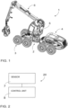
- Figure 1 shows a forestry machine 1, or to be more specific, a harvester.
- the forestry machine 1 may comprise, for example, a Figure 1 type harvester, a forwarder, or their combination, that is, a so-called combination machine, a processor, or another forestry machine known per se.
- the forestry machine 1 may comprise a carriage 2 which may consist of one, two or more body parts, moving means 3 which are adapted to the carriage 2 and which may comprise wheels, tracks, tandem axles, track system, or other structural parts known per se and needed for the forestry machine to move, and these may be adapted in connection with one or more body parts in each particular case.
- the forestry machine 1 may further comprise a primary power source 4, a hydraulic system (unnumbered), a cabin 5 adapted on the carriage, and/or a boom or boom structure 6 adapted to the carriage or cabin.
- the cabin 5 and/or boom/boom structure 6 may be adapted foldably and/or rotatably in relation to the carriage.
- boom 6 is also used to refer to boom structures consisting of more than one boom.
- Figure 2 is a schematic view or a control arrangement 20 in a forestry machine 1.
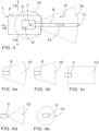
- Figure 3 is a schematic top view of a forestry machine, sector, and safety zone.
- the forestry machine comprises at least one cabin 5 and at least one boom 6.
- the control system comprises at least one sensor 7 and at least one control unit 8.
- the sensor 7 is adapted to detect at least one object 9 in the area of at least one predetermined sector 10.
- the sector 10 is focused in the area between the cabin 5 and boom end 11.
- Boom end 11 refers to the end of a boom or boom structure, which is not adapted to the forestry machine 1. In other words, boom end 11 refers to the end that is opposite in relation to the end of the boom or boom structure fixed to the forestry machine 1.
- a tool 12 such as a harvester head or a grab, may be adapted.
- the form of the sector 10 may be a circle sector as in Figure 3 , a cut circle sector as in Figure 4a , isosceles trapezoid as in Figure 4b , rectangle as in Figure 4c , a triangle as in Figure 4d , or circle as in Figure 4e .
- the sector may be, as seen from the side of the forestry machine, for example a circle sector, a cut circle sector, isosceles trapezoid, rectangle, triangle, or circle.
- the sector 10 may also extend over the cabin 5 and/or boom 6.
- the sector 10 may be defined as fully outside the cabin 5 as in Figure 4d , or to partially cover the cabin 5 as in Figures 3 and 4c , or to fully cover the cabin 5 as in Figures 4a, 4b and 4e .
- the sector 10 may be defined fully outside the cabin 5 or to partially or fully cover the cabin 5.
- the cabin 5 may be entirely or partly adapted inside the sector 10 or entirely outside it.
- the sector 10 may be adapted to extend around the cabin 5, for example in such a manner that the sector 10 extends on one, two, three, or four sides of the cabin 5 and/or over the cabin 5, but does not extend to the area of the cabin.
- the sector 10 may comprise the entire detection area of the sensor 7, in other words, the area where the objects 9 are that the sensor can or is adapted to detect.
- the sector 10 may comprise the entire maximum detection area of the sensor 7 or the entire area that the sensor 7 is adapted to observe by defining, for example, measurement directions.
- the sector 10 may comprise a determined part of the maximum detection area of the sensor 7 or of the area that the sensor 7 is adapted to observe.
- the sensor 7 is adapted to detect at least one of the following: the location data of a detected object 9 on at least two different instants of time, and the speed of the detected object 9.
- the location data of the object 9 may comprise the distance of the object 9 from the cabin 5, for example from the outer edge of the cabin, or the distance of the object 9 from a specific measurement point.
- the location data of the object 9 may comprise the location of the object 9 in one, two, or three dimensions in relation to a specific measurement point, or in a predetermined coordinate system.
- the measurement point may be determined in the cabin 5, for example the centre point of the cabin, or a predetermined point on the outer edge of the cabin, the boom 6 such as the end 11 of the boom, a selected joint of the boom or another point on the boom, the sensor 7, or another suitable point on the forestry machine 1.
- the sensor 7 is adapted to detect the speed of the object 9, such as the speed in relation to the cabin 5, boom 6, boom end 11, carriage 2 of the forestry machine or the surroundings of the forestry machine 1, or another measurement point or coordinate system.
- the object 9 may be considered to be moving in relation to the cabin 5 when the object 9 is moving and the cabin 5 is stationary, when the cabin 5 is moving and the object 9 is stationary, or when the object 9 and cabin 5 are moving in different directions and/or at different speeds.
- the object 9 may be considered moving towards the cabin 5 also in a situation in which the object 9 is stationary and the cabin 5 is moving in relation to it, towards the object 9, for example.
- the control unit 8 is adapted to check the need to cause a change in the control of the forestry machine 1 by checking at least one predetermined control criterion in response to the detected direction of travel of the detected object 9 is towards the cabin 5 within the area of said predetermined sector 10.
- the control unit 8 is adapted to cause a change in the control of the forestry machine 1 in response to the detected direction of travel of the detected object 9 is towards the cabin 5 within the area of the predetermined sector 10 and that said at least one predetermined criterion is fulfilled.
- the direction of travel may be considered to be towards the cabin 5 within the sector 10 area, if at least the latest detected location of the object 9 is located at least partly within the sector 10.
- the direction of travel may be considered to be towards the cabin 5 within the sector 10 area, if instead or in addition to this the object 9 has been detected within the area of the sector 10 and either the distance of the object 9 in relation to the cabin 5 has become shorter or the direction of movement of the object is such that the distance of the object 9 to the cabin 5 is becoming shorter.
- the direction of travel may be considered to be towards the cabin 5 within the sector 10 area, if the direction of travel of the object 9 in relation to the cabin is such that if the movement were to continue unchanged, the object 9 would hit the cabin 5.
- the reference point may comprise a point to which the distance of the object 9 from the cabin is determined, a measurement point, or the zero point of a coordinate system. If the reference point is not immobile in relation to the cabin 5, it is possible to determine, in addition to the location data of the object 9, also the location data of the cabin 5 in relation to the reference point. In such a case, the location data of the object 9 in relation to the cabin 5 may be determined on the basis of the location data of the object 9 and cabin 5, for example, in the control unit 5 and/or the speed of the object 9 in relation to the cabin 5 may be determined from the speed data of the object 9 and cabin 5 in relation to the reference point, for example, in the control unit.
- control unit 8 may further be adapted to determine the angle of the detected direction of travel in relation to the cabin.
- control unit 8 may be adapted to determine the direction of travel of the object 9 and the angle of this direction of travel in at least one plane in relation to the cabin 5, for example the centre point of the cabin 5, the closest point of the outer edge of the cabin 5 in relation to the object, or another suitable measurement point.
- control unit 8 may be adapted to determine the speed of movement of the detected object 9 in relation to the cabin 5.
- the speed of the object 9 in relation to the cabin 5 may be determined in addition to the direction of travel of the object 9, and in addition to or instead of determining the angle of the direction of travel.
- control unit 8 may be adapted to cause a change in the control of the forestry machine 1 in response to the determined speed of movement of the detected object 9 in relation to the cabin exceeds a speed considered safe.
- a speed that is considered safe may comprise a speed considered safe in a standard or reference literature relating to machine safety, or a speed that has been determined on the basis of the feed rate of the detected object, such as a trunk, average reaction time of a user and/or the distance between the cabin 5 and the detected object, such as the boom end 11, such as the average use position of the cabin 5 and boom end 11, or use position at the reference time.
- control unit 8 may be adapted to cause a change in the control of the forestry machine 1 in response to the determined speed of the detected object 9 in relation to the cabin being at least 3 m/s. In a second embodiment, the control unit 8 may be adapted to cause a change in the control of the forestry machine 1 in response to the determined speed of the detected object 9 in relation to the cabin being at least 4 m/s. In a third embodiment, the control unit 8 may be adapted to cause a change in the control of the forestry machine 1 in response to the determined speed of the detected object 9 in relation to the cabin being at least 5 m/s.
- At least one sensor 7 may be adapted to detect at least one dimension of the detected object 9.
- at least one dimension of the detected object 9 may be determined, in addition to or instead of the sensor 7, in the control unit 8, based on the information composed by the sensor 7, for example.
- the dimension of the object 9 may comprise the height, length and/or width of the object 9 as seen from the direction of the cabin 5, as seen from the reference point and/or in a predetermined coordinate system, such as the coordinate system used in determining the location data.
- the control unit 8 may be adapted to cause a change in the control of the forestry machine 1 in response to the dimension of the detected object 9 being at least 5 cm.
- control unit 8 may be adapted to cause a change in the control of the forestry machine 1 in response to the dimension of the detected object 9 being at least 1.5 cm or 3 cm.
- at least one dimension of the object 9 may in this case form the control criterion, or at least one of the control criteria, and this control criterion may be considered fulfilled when the dimension at least equals the predetermined one, such as at least 1.5 cm, at least 3 cm, or at least 5 cm.
- control unit 8 may be adapted to cause a change in the control of the forestry machine 1 by forming at least one control command which is adapted to affect the control of the forestry machine 1.
- the change to the control of the forestry machine 1 may comprise slowing down or stopping feed rollers, at least one actuator of the driving transmission, at least one actuator of the boom, or another function of the forestry machine or operation of an actuator.
- the change in the control of the forestry machine may be gradual whereby the operation is first slowed down a little and gradually or steplessly more until the operation is finally stopped.
- at least one control criteria may similarly have one, two, or more stages or threshold values.
- any of the aforementioned operations may be, for example, slowed down when a first threshold value of a control criterion is exceeded, and the operation may be stopped when a second threshold value of the control criterion is exceeded, or the operation may be slowed down when a first threshold value of a control criterion is exceeded, and the operation may be slowed down more when a second threshold value is exceeded.
- the determined speed of the object 9 in relation to the cabin 5 may have, for example, one, two, or more threshold values, such as a first threshold value of 3 m/s and a second threshold value of 4 m/s or 5 m/s.
- the dimension of the object 9 may have two or three threshold values, such as 1.5 cm, 3 cm and/or 5cm, or other appropriate threshold values which may constitute the first threshold value and/or second threshold value.
- At least one sensor 7, 7' is adapted to detect at least one object 9, 9' which is not a structural part of the forestry machine 1, within the area of a predetermined safety zone 13.
- the sensor by means of which the object 9 within the area of the safety zone 13 is detected may be the same sensor 7 by means of which an object or objects are detected in the sector 10 area, or a separated sensor 7'.
- an object that is detected within the area of the safety zone may be the same object 9 that is detected in the sector 10 area or a different object 9'.
- the safety zone may at least partly differ from the predetermined sector 10 area.
- the safety zone 13 and sector 10 may at least partly overlap and/or the safety zone 13 may comprise at least part of the area of the sector 10.
- the safety zone 13 may be located entirely inside the sector 10, comprising a part of the sector 10.
- the safety zone 13 may comprise the entire sector 10, that is, the safety zone 13 and sector 10 may be equal.
- At least one control unit 8 may be adapted to cause a change in the control of the forestry machine 1 in response to the sensor 7, 7' having detected an object 9, 9' not belonging to the forestry machine 1 in the safety zone.
- the control unit 8 may be adapted to cause the operation of the forestry machine 1 to stop in response to the detection of an object 9, 9' that is not a structural part of the forestry machine 1, in the area of the safety zone 13. In this context, stopping the operation of the forestry machine does not refer to stopping the operation of the forestry machine 1 or its control system, such as the control unit.
- stopping the operation may, depending on the embodiment and type of detected object 9, 9', refer to stopping the feed rollers, directing the driving transmission operation to stop the driving movement of the forestry machine 1, or controlling the boom 6 to stop an object 9, 9', such as a trunk 17, adapted to the boom.
- At least one said sensor 7, 7' is adapted to at least one of the following; in connection with a cabin window, above the cabin outside the cabin, top part of the cabin inside the cabin, body of the forestry machine, boom of the forestry machine, front body of the forestry machine, rear body of the forestry machine, and a structure external to the forestry machine moving with the forestry machine.
- the predetermined sector 10 is directed from the cabin of the forestry machine towards at least the main working direction 14 of the boom 6, as in Figures 3 and 4a-4e .
- the main working direction of the boom 6 refers to the direction to which the working of the boom or boom structure in the neutral position of the cabin 5 is for the most part directed.
- the neutral position of the cabin 5 refers to the normal, non-rotational direction of the cabin 5 during transport, for example.
- the main working direction of the boom 6 is directed in the neutral position of the cabin forward as seen from the cabin 5 or an operator's seat (not shown) adapted in the cabin, that is, forward from an operator sitting in the seat.
- the main working direction of the boom 6 may be from the cabin 5 towards the end 11 of the boom.
- Such an embodiment may be an embodiment where the sector 10 is defined in relation to the direction of the cabin 5. such as a rotating cabin, and/or boom 6, whereby the sector 10 rotates together with the cabin 5 and/or boom 6.
- the predetermined sector 10 is additionally directed from the cabin 5 of the forestry machine to at least two transverse sides 15, in relation to the boom main working direction, as in Figures 4a, 4b, 4c and 4e , for example. In an embodiment, the predetermined sector 10 is additionally directed from the forestry machine cabin to the opposite direction 16 in relation to the boom main working direction 14, as in Figure 4e , for example.
- the predetermined sector 10 extends to substantially the distance matching the reach of the boom 6 from the cabin 5 of the forestry machine.
- Figure 5 shows a method for controlling a forestry machine.
- the forestry machine 1 comprises at least one cabin 5 and at least one boom 6.
- at least one sensor 7 at least one object 9 is detected 51 within the area of at least one predetermined sector 10.
- the sector 10 is focused in the area between the cabin and the boom end 11.
- At least one control unit 8 at least the direction of travel of said detected object 9 is determined 53 in relation to the cabin 5 on the basis of the location data of said object 9 at two detected instants of time, at least, and/or the detected speed of the object 9.
- the need is checked 54 to cause a change in the control of the forestry machine 1 by checking at least one predetermined control criterion in response to the detected direction of travel of the detected object 9 being towards the cabin 5 within the area of said predetermined sector 10.
- a change is caused 55 in the control of the forestry machine 1 by the control unit in response to the determined direction of travel of the detected object 9 is towards the cabin 5 within the area of said predetermined sector 10 and said at least one predetermined control criterion is fulfilled.
- the change in the control of the forestry machine 1 may in such a case be carried out only when the determined direction of travel of the detected object 9 is towards the cabin 5 within the area of said predetermined sector 10 and in addition said at least one predetermined control criterion is fulfilled.
- a change in the control of the forestry machine 1 may be carried out only when the determined direction of travel of the detected object 9 is towards the cabin 5 within the area of said predetermined sector 10 at substantially the same time as said at least one predetermined control criterion is fulfilled.
- the method it is further detected by means of at least one sensor 7, 7' at least one object 9, 9' which object 9, 9' is not a structural part of the forestry machine 1, in the area of the predetermined safety zone 13.
- at least one control unit 8 may be employed to cause a change in the control of the forestry machine 1 in response to the sensor 7, 7' having detected said object 9, 9' not belonging to the forestry machine 1, in the safety zone 13.
- the safety zone 13 may at least partly differ from the predetermined sector 10 area.
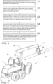
- FIG 6 is a schematic view of a forestry machine 1 in perspective.
- the forestry machine may correspond as to its essential parts one of the forestry machines 1 described in this description.
- the forestry machine of Figure 6 is a harvester by in the various embodiments the forestry machine 1 may comprise a load machine/forwarder, a combination machine, processor, or another forestry machine known per se.
- a tool 12 is adapted to the boom 6 of the forestry machine 1.
- the tool 12 may in some embodiments be a tool suitable for grabbing a trunk 17, for example, and/or for its handling, such as a harvester head or a grab.
- the trunk 17 may in this case form the object 9, 9', if it during the grabbing to the trunk and/or handling it ends up in the area of the predetermined sector 10 and/or safety zone 13.
- Figure 6 shows an example of a situation where the longitudinal axis 18 of the trunk is directed towards the cabin. 5. If the trunk 17 moves in this case in the direction of its longitudinal axis 18, for example, or in another direction so that the distance between the trunk 17 and the cabin 5 is reduced, the trunk 17 may form the detected object 9 and its direction of travel may be considered to be directed towards the cabin 5.
- the trunk 17, which as mentioned in the above, may also from the detected object, may move towards the cabin 5 either so that the cabin 5 moves and the trunk 17 stays put, so that the trunk 17 is moved with the boom 6 towards the cabin 5, or so that the trunk 17 is fed by a tool 12, such as a harvester head, towards the cabin 5.
- a tool 12 such as a harvester head
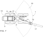
- Figure 7 shows a similar forestry machine 1 and situation as Figure 6 , but as seen from above.
- Figure 7 also illustrates a sector 10 and safety zone 7 according to an embodiment.
Landscapes
- Engineering & Computer Science (AREA)
- General Engineering & Computer Science (AREA)
- Mechanical Engineering (AREA)
- Life Sciences & Earth Sciences (AREA)
- Remote Sensing (AREA)
- Radar, Positioning & Navigation (AREA)
- Environmental Sciences (AREA)
- Forests & Forestry (AREA)
- Ecology (AREA)
- Biodiversity & Conservation Biology (AREA)
- Operation Control Of Excavators (AREA)
- Component Parts Of Construction Machinery (AREA)
- Control Of Position, Course, Altitude, Or Attitude Of Moving Bodies (AREA)
Claims (13)
- Forstmaschine (1), die mindestens eine Kabine (5), mindestens einen Ausleger (6) und eine Steueranordnung umfasst, wobei die Steueranordnung Folgendes umfasstmindestens einen Sensor (7), der angepasst ist, mindestens ein Objekt (9) im Bereich von mindestens einer vorbestimmten Region (10) zu detektieren, wobei die Region (10) im Bereich zwischen der Kabine (5) und dem Auslegerende (11) konzentriert ist, und wobei der Sensor (7) ferner angepasst ist, mindestens eines von Folgendem zu detektieren: den Ortsdaten des detektierten Objekts (9) zu mindestens zwei verschiedenen Zeitinstanzen und der Geschwindigkeit des detektierten Objekts (9), sowiemindestens eine Steuereinheit (8), die angepasst ist, mindestens die Fortbewegungsrichtung des detektierten Objekts (9) mit Bezug auf die Kabine (5) zu zwei verschiedenen Zeitinstanzen zu bestimmen, auf Basis der detektierten Ortsinformationen und/oder der detektierten Geschwindigkeit des Objekts (9) durch Prüfen eines vorbestimmten Steuerkriteriums in Reaktion darauf, dass die detektierte Bewegungsrichtung des detektierten Objekts (9) zur Kabine (5) im Bereich der vorbestimmten Region (10) gerichtet ist, mindestens ein Erfordernis zum Veranlassen einer Änderung der Steuerung einer Forstmaschine (1) zu prüfen und in Reaktion darauf, dass die detektierte Bewegungsrichtung des detektierten Objekts (9) zur Kabine (5) im Bereich der vorbestimmten Region (10) gerichtet ist, und auf die Erfüllung des mindestens einen vorbestimmten Steuerkriteriums eine Änderung der Steuerung der Forstmaschine (1) zu veranlassen.
- Forstmaschine nach Anspruch 1, wobei die Steuereinheit (8) ferner angepasst ist, den Winkel der Bewegungsrichtung des detektierten Objekts (9) mit Bezug auf die Kabine (5) zu bestimmen.
- Forstmaschine nach Anspruch 1 oder 2, wobei die Steuereinheit (8) ferner angepasst ist, die Bewegungsgeschwindigkeit des detektierten Objekts (9) mit Bezug auf die Kabine (5) zu bestimmen.
- Forstmaschine nach Anspruch 3, wobei die Bewegungsgeschwindigkeit des detektierten Objekts (9) mit Bezug auf die Kabine (5) mindestens eines der Steuerkriterien bildet, wodurch die Steuereinheit (8) angepasst ist, in Reaktion darauf, dass die bestimmte Geschwindigkeit des detektierten Objekts (9) mit Bezug auf die Kabine (5) mindestens 3 m/s beträgt, eine Änderung der Steuerung der Forstmaschine (1) zu veranlassen.
- Forstmaschine nach einem der Ansprüche 1 bis 4, wobei die Steuereinheit (8) angepasst ist, durch Bilden von mindestens einem Steuerbefehl, der angepasst ist, die Steuerung der Forstmaschine (1) zu beeinträchtigen, eine Änderung der Steuerung der Forstmaschine (1) zu veranlassen.
- Forstmaschine nach einem der Ansprüche 1 bis 5, wobei mindestens ein Sensor (7, 7') angepasst ist, im Bereich einer vorbestimmten Sicherheitszone (13) mindestens ein Objekt (9, 9') zu detektieren, das kein Strukturteil der Forstmaschine (1) ist, und bei dem
mindestens eine Steuereinheit (8) angepasst ist, in Reaktion darauf, dass der Sensor (7. 7') das Objekt (9, 9'), das nicht zur Forstmaschine (1) gehört, in der Sicherheitszone (13) detektiert, eine Änderung der Steuerung der Forstmaschine (1) zu veranlassen. - Forstmaschine nach Anspruch 6, wobei sich die Sicherheitszone (13) mindestens teilweise vom Bereich der vorbestimmten Region (10) unterscheidet.
- Forstmaschine nach Anspruch 6 oder 7, wobei die vorbestimmte Sicherheitszone (13) einen Bereich umfasst, der sich von der Kabine (5) der Forstmaschine (1) zu einem Abstand von 1,5 Meter erstreckt.
- Forstmaschine nach einem der Ansprüche 6 bis 8, wobei die Steuereinheit (8) angepasst ist, in Reaktion auf die Detektion eines Objekts (9, 9'), das kein Strukturteil der Forstmaschine (1) ist, im Bereich der Sicherheitszone (13) zu veranlassen, dass der Betrieb der Forstmaschine (1) gestoppt wird.
- Forstmaschine nach einem der Ansprüche 1 bis 9, wobei die vorbestimmte Region (10) von der Kabine (5) der Forstmaschine (1) mindestens zur Hauptarbeitsrichtung des Auslegers (6) gerichtet ist.
- Verfahren zum Steuern einer Forstmaschine, wobei die Forstmaschine (1) mindestens eine Kabine (5) und mindestens einen Ausleger (6) umfasst, wobei das Verfahren Folgendes umfasstDetektieren von mindestens einem Objekt (9) im Bereich von mindestens einer vorbestimmten Region (10) durch mindestens einen Sensor (7), wobei die Region (10) im Bereich zwischen der Kabine (5) und einem Auslegerende (11) konzentriert ist,Detektieren von mindestens einem von Folgendem durch den Sensor (7): den Ortsdaten des detektierten Objekts (9) zu mindestens zwei verschiedenen Zeitinstanzen und der Geschwindigkeit des detektierten Objekts (9),Bestimmen auf Basis der detektierten Ortsinformationen und/oder der detektierten Geschwindigkeit des Objekts (9) mindestens der Fortbewegungsrichtung des detektierten Objekts (9) mit Bezug auf die Kabine (5) durch mindestens eine Steuereinheit (8) zu zwei verschiedenen Zeitinstanzen,Prüfen eines Erfordernis zum Veranlassen einer Änderung der Steuerung der Forstmaschine (1) durch die Steuereinheit (8) durch Prüfen von mindestens einem vorbestimmten Steuerkriterium in Reaktion darauf, dass die detektierte Fortbewegungsrichtung des detektierten Objekts (9) zur Kabine (5) im Bereich der vorbestimmten Region (10) verläuft, undVeranlassen einer Änderung der Steuerung der Forstmaschine (1) durch die Steuereinheit (8) in Reaktion darauf, dass die bestimmte Fortbewegungsrichtung des detektierten Objekts (9) zur Kabine (5) im Bereich der vorbestimmten Region (10) verläuft und das vorbestimmte Steuerkriterium erfüllt ist.
- Verfahren nach Anspruch 11, bei dem fernerDetektieren von mindestens einem Objekt (9, 9'), das kein Strukturteil der Forstmaschine (1) ist, durch mindestens einen Sensor (7, 7') im Bereich einer vorbestimmten Sicherheitszone (13), wobei sich die Sicherheitszone (13) mindestens teilweise vom Bereich der vorbestimmten Region (10) unterscheidet, und bei demVeranlassen einer Änderung der Steuerung der Forstmaschine (1) durch mindestens eine Steuereinheit (8) in Reaktion darauf, dass der Sensor (7, 7') das Objekt (9, 9'), das nicht zur Forstmaschine (1) gehört, in der Sicherheitszone (13) detektiert.
- Verfahren nach Anspruch 12, wobei sich die Sicherheitszone (13) mindestens teilweise vom Bereich der vorbestimmten Region (10) unterscheidet.
Applications Claiming Priority (2)
| Application Number | Priority Date | Filing Date | Title |
|---|---|---|---|
| FI20185712A FI128122B (fi) | 2018-08-29 | 2018-08-29 | Ohjausjärjestely ja menetelmä metsäkoneen ohjaamiseksi |
| PCT/FI2019/050609 WO2020043946A1 (en) | 2018-08-29 | 2019-08-28 | Control arrangement and method for controlling a forestry machine |
Publications (3)
| Publication Number | Publication Date |
|---|---|
| EP3843532A1 EP3843532A1 (de) | 2021-07-07 |
| EP3843532A4 EP3843532A4 (de) | 2022-06-01 |
| EP3843532B1 true EP3843532B1 (de) | 2024-12-04 |
Family
ID=68807850
Family Applications (1)
| Application Number | Title | Priority Date | Filing Date |
|---|---|---|---|
| EP19854147.6A Active EP3843532B1 (de) | 2018-08-29 | 2019-08-28 | Forstmaschine und verfahren zur steuerung einer forstmaschine |
Country Status (5)
| Country | Link |
|---|---|
| US (1) | US12259089B2 (de) |
| EP (1) | EP3843532B1 (de) |
| CA (1) | CA3108877A1 (de) |
| FI (1) | FI128122B (de) |
| WO (1) | WO2020043946A1 (de) |
Families Citing this family (2)
| Publication number | Priority date | Publication date | Assignee | Title |
|---|---|---|---|---|
| SE543752C2 (en) * | 2019-11-15 | 2021-07-13 | Log Max Ab | A harvesting head for length determination of a tree truck and an associated method |
| FI130760B1 (fi) * | 2022-01-26 | 2024-02-29 | Ponsse Oyj | Metsäkoneen istuimen säätöjärjestelmä |
Family Cites Families (55)
| Publication number | Priority date | Publication date | Assignee | Title |
|---|---|---|---|---|
| US3898652A (en) * | 1973-12-26 | 1975-08-05 | Rashid Mary D | Vehicle safety and protection system |
| SE9603880D0 (sv) * | 1996-10-23 | 1996-10-23 | Bengt Soervik | Förfarande och anordning för skoglig planering |
| DE19650168C2 (de) * | 1996-12-04 | 2001-10-04 | Volkswagen Ag | Verfahren und Vorrichtung zur Geschwindigkeitsregelung eines Kraftfahrzeuges |
| US6223110B1 (en) * | 1997-12-19 | 2001-04-24 | Carnegie Mellon University | Software architecture for autonomous earthmoving machinery |
| US6363632B1 (en) * | 1998-10-09 | 2002-04-02 | Carnegie Mellon University | System for autonomous excavation and truck loading |
| AU6894100A (en) * | 1999-08-06 | 2001-03-05 | Roadrisk Technologies, Llc | Methods and apparatus for stationary object detection |
| US6429789B1 (en) * | 1999-08-09 | 2002-08-06 | Ford Global Technologies, Inc. | Vehicle information acquisition and display assembly |
| JP2001064992A (ja) * | 1999-08-31 | 2001-03-13 | Sumitomo Constr Mach Co Ltd | 油圧掘削機等の建設機械における干渉防止装置 |
| DE10053061A1 (de) * | 2000-10-26 | 2002-05-08 | Dornier Gmbh | Verfahren zur adaptiven Zielverarbeitung in einem kraftfahrzeugradar |
| US20040254728A1 (en) * | 2002-10-25 | 2004-12-16 | Poropat George Vladimir | Collision warning system and method |
| US7243013B2 (en) * | 2002-11-13 | 2007-07-10 | Ford Global Technologies, Llc | Vehicle radar-based side impact assessment method |
| US6961006B2 (en) * | 2003-04-05 | 2005-11-01 | Delphi Technologies, Inc. | Object detection for a stopped vehicle |
| US7320349B2 (en) | 2003-12-18 | 2008-01-22 | Caterpillar Inc. | Tree harvester |
| US7409295B2 (en) * | 2004-08-09 | 2008-08-05 | M/A-Com, Inc. | Imminent-collision detection system and process |
| JP2006144349A (ja) | 2004-11-18 | 2006-06-08 | Hitachi Constr Mach Co Ltd | 建設機械の安全装置 |
| JP2006264416A (ja) * | 2005-03-22 | 2006-10-05 | Takata Corp | 対象物検知システム、保護システム、車両 |
| KR100702179B1 (ko) * | 2005-05-06 | 2007-04-02 | 볼보 컨스트럭션 이키프먼트 홀딩 스웨덴 에이비 | 중장비 운전실 보호구조 |
| DE102005054359A1 (de) * | 2005-11-15 | 2007-05-16 | Leuze Lumiflex Gmbh & Co Kg | Schutzeinrichtung |
| US8180532B2 (en) * | 2006-05-26 | 2012-05-15 | Deere & Company | Vector controlled leveling system for a forestry machine |
| US8010261B2 (en) * | 2007-05-23 | 2011-08-30 | Cnh America Llc | Automatic steering correction of an agricultural harvester using integration of harvester header row sensors and harvester auto guidance system |
| JP5309633B2 (ja) * | 2007-11-16 | 2013-10-09 | アイシン・エィ・ダブリュ株式会社 | 車両制御装置、車両制御方法及びコンピュータプログラム |
| JP2009121175A (ja) | 2007-11-16 | 2009-06-04 | Caterpillar Japan Ltd | 作業用機械における干渉防止装置 |
| DE102008003205A1 (de) * | 2008-01-04 | 2009-07-09 | Wabco Gmbh | Vorrichtung, Verfahren und Computerprogramm zur Kollisionsvermeidung oder zur Verminderung der Kollisionsschwere infolge einer Kollision für Fahrzeuge, insbesondere Nutzfahrzeuge |
| DE102008015277A1 (de) * | 2008-03-20 | 2009-09-24 | Deere & Company, Moline | Verfahren und Vorrichtung zur Lenkung einer zweiten landwirtschaftlichen Maschine, die relativ zu einer ersten landwirtschaftlichen Maschine über ein Feld lenkbar ist |
| US8244408B2 (en) * | 2009-03-09 | 2012-08-14 | GM Global Technology Operations LLC | Method to assess risk associated with operating an autonomic vehicle control system |
| FI121726B (fi) | 2009-06-18 | 2011-03-31 | Jussi-Pekka Rikhard Usenius | Menetelmä harvesterin kaatopään valvomiseksi |
| FI20090447A7 (fi) * | 2009-11-26 | 2011-05-27 | Ponsse Oyj | Menetelmä ja laite metsäkoneen yhteydessä |
| US8682541B2 (en) * | 2010-02-01 | 2014-03-25 | Trimble Navigation Limited | Sensor unit system |
| US8768609B2 (en) * | 2010-02-01 | 2014-07-01 | Trimble Navigation Limited | Sensor unit system |
| JP2012019702A (ja) | 2010-07-12 | 2012-02-02 | Hitachi Constr Mach Co Ltd | 作業機械におけるプロセッサ制御装置 |
| KR101029096B1 (ko) * | 2010-11-18 | 2011-04-13 | 김은숙 | 차량의 측면 충돌 회피 방법 |
| US8744693B2 (en) * | 2010-11-22 | 2014-06-03 | Caterpillar Inc. | Object detection system having adjustable focus |
| CA2828721C (en) | 2012-10-10 | 2022-05-17 | Waratah Nz Limited | Method and apparatus for determining a recommended operation of a timber-working device having an associated hazard zone |
| AU2013203666B2 (en) | 2012-10-10 | 2015-05-28 | Waratah Nz Limited | Method, apparatus, and system for controlling a timber-working device |
| US20140133944A1 (en) * | 2012-11-12 | 2014-05-15 | Lts Scale Company, Llc | Detection System Usable In Forklift Apparatus |
| FI20135625L (fi) | 2013-06-05 | 2014-12-22 | Ponsse Oyj | Menetelmä ja sovitelma puukappaleen mittaamiseksi |
| BR112016013628B1 (pt) * | 2013-12-20 | 2020-04-28 | Komatsu Forest Ab | método e arranjo para o nivelamento lateral de cabeça de trabalho com madeira e máquina florestal |
| US9523180B2 (en) * | 2014-04-28 | 2016-12-20 | Deere & Company | Semi-automatic material loading |
| US9487931B2 (en) * | 2014-09-12 | 2016-11-08 | Caterpillar Inc. | Excavation system providing machine cycle training |
| JP6477259B2 (ja) | 2015-05-28 | 2019-03-06 | コベルコ建機株式会社 | 建設機械 |
| ITUB20151930A1 (it) | 2015-07-03 | 2017-01-03 | Soilmec Spa | Sistema e metodo di sicurezza per la rilevazione di una condizione di rischio in una regione situata in prossimita' di una macchina operatrice, quale una macchina di perforazione o simile. |
| EP3243609A1 (de) * | 2016-05-09 | 2017-11-15 | OpiFlex Automation AB | Zaunfreies industrierobotersystem |
| US20190057606A1 (en) * | 2017-08-15 | 2019-02-21 | Continental Automotive Systems, Inc. | Warning to vulnerable users in dangerous situation |
| FI128475B (fi) * | 2018-08-30 | 2020-06-15 | Ponsse Oyj | Järjestely ja menetelmä metsäkoneen kuorman purkamisen hallintaan |
| US10905054B2 (en) * | 2018-11-13 | 2021-02-02 | Deere & Company | Controlling the operation of forestry machines based on data acquisition |
| US10950114B2 (en) * | 2018-12-12 | 2021-03-16 | Lantern Holdings, LLC | Lockout device and system |
| US10872514B1 (en) * | 2019-08-14 | 2020-12-22 | The Boeing Company | Safety system for tracking movable objects during vehicle production |
| US11730094B2 (en) * | 2020-02-28 | 2023-08-22 | Komatsu Ltd. | Forestry machine and method of operating forestry machine |
| WO2021192655A1 (ja) * | 2020-03-27 | 2021-09-30 | 日立建機株式会社 | 作業機械 |
| IT202000025426A1 (it) * | 2020-10-27 | 2022-04-27 | Microtec Srl | Testa di lavorazione per una macchina forestale |
| WO2023060285A1 (en) * | 2021-10-08 | 2023-04-13 | Clutterbot, Inc. | Large object robotic front loading algorithm |
| US12148296B2 (en) * | 2021-11-04 | 2024-11-19 | Ford Global Technologies, Llc | Sensor optimization |
| US20230150358A1 (en) * | 2021-11-18 | 2023-05-18 | Caterpillar Inc. | Collision avoidance system and method for avoiding collision of work machine with obstacles |
| US12110660B2 (en) * | 2022-02-24 | 2024-10-08 | Caterpillar Inc. | Work machine 3D exclusion zone |
| EP4305954A1 (de) * | 2022-07-11 | 2024-01-17 | Deere & Company | System und verfahren zur erfassung der lasthöhe |
-
2018
- 2018-08-29 FI FI20185712A patent/FI128122B/fi active IP Right Grant
-
2019
- 2019-08-28 US US17/271,955 patent/US12259089B2/en active Active
- 2019-08-28 WO PCT/FI2019/050609 patent/WO2020043946A1/en not_active Ceased
- 2019-08-28 CA CA3108877A patent/CA3108877A1/en active Pending
- 2019-08-28 EP EP19854147.6A patent/EP3843532B1/de active Active
Also Published As
| Publication number | Publication date |
|---|---|
| WO2020043946A1 (en) | 2020-03-05 |
| FI20185712A1 (fi) | 2019-10-15 |
| US12259089B2 (en) | 2025-03-25 |
| CA3108877A1 (en) | 2020-03-05 |
| FI128122B (fi) | 2019-10-15 |
| US20210324998A1 (en) | 2021-10-21 |
| EP3843532A1 (de) | 2021-07-07 |
| EP3843532A4 (de) | 2022-06-01 |
Similar Documents
| Publication | Publication Date | Title |
|---|---|---|
| KR102038848B1 (ko) | 물류 취급 차량용 물체 트래킹 및 조향 조작 | |
| US8108090B2 (en) | Straddle carrier with automatic steering | |
| RU2564928C1 (ru) | Маневры при управлении поворотом погрузочно-разгрузочных транспортных средств | |
| RU2568046C2 (ru) | Подъемно-транспортная машина | |
| US9637123B2 (en) | Method for operating a self-propelled mobile platform | |
| JP2000001298A (ja) | ポットホ―ル及び/又は障害物検出及び回避システムを備えた空中作業用プラットホ―ム | |
| KR20120052393A (ko) | 원격 작동되는 자재 취급 차량을 위한 조향 보정 | |
| EP3843532B1 (de) | Forstmaschine und verfahren zur steuerung einer forstmaschine | |
| KR101638839B1 (ko) | 중장비 접근감시 및 작동정지 제어시스템 | |
| US11828046B2 (en) | Object responsive control system for a work machine | |
| EP3269679B1 (de) | Flurförderer | |
| RU2785765C2 (ru) | Управляющее устройство и способ управления лесозаготовительной машиной | |
| EP3269680A1 (de) | Flurförderer | |
| ES3048788T3 (en) | System for preventing collisions between a charging device and a load vehicle | |
| US20250122057A1 (en) | Loading control device | |
| KR20240033843A (ko) | 건설 기계의 충돌 방지 시스템 및 방법 | |
| EP3269678B1 (de) | Flurförderer | |
| KR20230161814A (ko) | 건설 기계의 충돌 방지 장치 및 방법 | |
| KR20240015786A (ko) | 건설 기계의 충돌 방지 시스템 및 방법 |
Legal Events
| Date | Code | Title | Description |
|---|---|---|---|
| STAA | Information on the status of an ep patent application or granted ep patent |
Free format text: STATUS: THE INTERNATIONAL PUBLICATION HAS BEEN MADE |
|
| STAA | Information on the status of an ep patent application or granted ep patent |
Free format text: STATUS: REQUEST FOR EXAMINATION WAS MADE |
|
| PUAI | Public reference made under article 153(3) epc to a published international application that has entered the european phase |
Free format text: ORIGINAL CODE: 0009012 |
|
| 17P | Request for examination filed |
Effective date: 20210309 |
|
| AK | Designated contracting states |
Kind code of ref document: A1 Designated state(s): AL AT BE BG CH CY CZ DE DK EE ES FI FR GB GR HR HU IE IS IT LI LT LU LV MC MK MT NL NO PL PT RO RS SE SI SK SM TR |
|
| DAV | Request for validation of the european patent (deleted) | ||
| DAX | Request for extension of the european patent (deleted) | ||
| A4 | Supplementary search report drawn up and despatched |
Effective date: 20220429 |
|
| RIC1 | Information provided on ipc code assigned before grant |
Ipc: F16P 3/14 20060101ALI20220422BHEP Ipc: A01G 23/083 20060101AFI20220422BHEP |
|
| GRAP | Despatch of communication of intention to grant a patent |
Free format text: ORIGINAL CODE: EPIDOSNIGR1 |
|
| STAA | Information on the status of an ep patent application or granted ep patent |
Free format text: STATUS: GRANT OF PATENT IS INTENDED |
|
| INTG | Intention to grant announced |
Effective date: 20240624 |
|
| GRAS | Grant fee paid |
Free format text: ORIGINAL CODE: EPIDOSNIGR3 |
|
| GRAA | (expected) grant |
Free format text: ORIGINAL CODE: 0009210 |
|
| STAA | Information on the status of an ep patent application or granted ep patent |
Free format text: STATUS: THE PATENT HAS BEEN GRANTED |
|
| AK | Designated contracting states |
Kind code of ref document: B1 Designated state(s): AL AT BE BG CH CY CZ DE DK EE ES FI FR GB GR HR HU IE IS IT LI LT LU LV MC MK MT NL NO PL PT RO RS SE SI SK SM TR |
|
| REG | Reference to a national code |
Ref country code: CH Ref legal event code: EP |
|
| REG | Reference to a national code |
Ref country code: DE Ref legal event code: R096 Ref document number: 602019063115 Country of ref document: DE |
|
| REG | Reference to a national code |
Ref country code: IE Ref legal event code: FG4D |
|
| REG | Reference to a national code |
Ref country code: SE Ref legal event code: TRGR |
|
| REG | Reference to a national code |
Ref country code: LT Ref legal event code: MG9D |
|
| REG | Reference to a national code |
Ref country code: NL Ref legal event code: MP Effective date: 20241204 |
|
| PG25 | Lapsed in a contracting state [announced via postgrant information from national office to epo] |
Ref country code: HR Free format text: LAPSE BECAUSE OF FAILURE TO SUBMIT A TRANSLATION OF THE DESCRIPTION OR TO PAY THE FEE WITHIN THE PRESCRIBED TIME-LIMIT Effective date: 20241204 |
|
| PG25 | Lapsed in a contracting state [announced via postgrant information from national office to epo] |
Ref country code: FI Free format text: LAPSE BECAUSE OF FAILURE TO SUBMIT A TRANSLATION OF THE DESCRIPTION OR TO PAY THE FEE WITHIN THE PRESCRIBED TIME-LIMIT Effective date: 20241204 |
|
| PG25 | Lapsed in a contracting state [announced via postgrant information from national office to epo] |
Ref country code: BG Free format text: LAPSE BECAUSE OF FAILURE TO SUBMIT A TRANSLATION OF THE DESCRIPTION OR TO PAY THE FEE WITHIN THE PRESCRIBED TIME-LIMIT Effective date: 20241204 |
|
| PG25 | Lapsed in a contracting state [announced via postgrant information from national office to epo] |
Ref country code: ES Free format text: LAPSE BECAUSE OF FAILURE TO SUBMIT A TRANSLATION OF THE DESCRIPTION OR TO PAY THE FEE WITHIN THE PRESCRIBED TIME-LIMIT Effective date: 20241204 |
|
| PG25 | Lapsed in a contracting state [announced via postgrant information from national office to epo] |
Ref country code: NO Free format text: LAPSE BECAUSE OF FAILURE TO SUBMIT A TRANSLATION OF THE DESCRIPTION OR TO PAY THE FEE WITHIN THE PRESCRIBED TIME-LIMIT Effective date: 20250304 |
|
| PG25 | Lapsed in a contracting state [announced via postgrant information from national office to epo] |
Ref country code: LV Free format text: LAPSE BECAUSE OF FAILURE TO SUBMIT A TRANSLATION OF THE DESCRIPTION OR TO PAY THE FEE WITHIN THE PRESCRIBED TIME-LIMIT Effective date: 20241204 Ref country code: GR Free format text: LAPSE BECAUSE OF FAILURE TO SUBMIT A TRANSLATION OF THE DESCRIPTION OR TO PAY THE FEE WITHIN THE PRESCRIBED TIME-LIMIT Effective date: 20250305 |
|
| PG25 | Lapsed in a contracting state [announced via postgrant information from national office to epo] |
Ref country code: RS Free format text: LAPSE BECAUSE OF FAILURE TO SUBMIT A TRANSLATION OF THE DESCRIPTION OR TO PAY THE FEE WITHIN THE PRESCRIBED TIME-LIMIT Effective date: 20250304 |
|
| PG25 | Lapsed in a contracting state [announced via postgrant information from national office to epo] |
Ref country code: NL Free format text: LAPSE BECAUSE OF FAILURE TO SUBMIT A TRANSLATION OF THE DESCRIPTION OR TO PAY THE FEE WITHIN THE PRESCRIBED TIME-LIMIT Effective date: 20241204 |
|
| REG | Reference to a national code |
Ref country code: AT Ref legal event code: MK05 Ref document number: 1747073 Country of ref document: AT Kind code of ref document: T Effective date: 20241204 |
|
| PG25 | Lapsed in a contracting state [announced via postgrant information from national office to epo] |
Ref country code: SM Free format text: LAPSE BECAUSE OF FAILURE TO SUBMIT A TRANSLATION OF THE DESCRIPTION OR TO PAY THE FEE WITHIN THE PRESCRIBED TIME-LIMIT Effective date: 20241204 |
|
| PG25 | Lapsed in a contracting state [announced via postgrant information from national office to epo] |
Ref country code: PL Free format text: LAPSE BECAUSE OF FAILURE TO SUBMIT A TRANSLATION OF THE DESCRIPTION OR TO PAY THE FEE WITHIN THE PRESCRIBED TIME-LIMIT Effective date: 20241204 |
|
| PG25 | Lapsed in a contracting state [announced via postgrant information from national office to epo] |
Ref country code: IS Free format text: LAPSE BECAUSE OF FAILURE TO SUBMIT A TRANSLATION OF THE DESCRIPTION OR TO PAY THE FEE WITHIN THE PRESCRIBED TIME-LIMIT Effective date: 20250404 |
|
| PG25 | Lapsed in a contracting state [announced via postgrant information from national office to epo] |
Ref country code: PT Free format text: LAPSE BECAUSE OF FAILURE TO SUBMIT A TRANSLATION OF THE DESCRIPTION OR TO PAY THE FEE WITHIN THE PRESCRIBED TIME-LIMIT Effective date: 20250404 |
|
| PG25 | Lapsed in a contracting state [announced via postgrant information from national office to epo] |
Ref country code: EE Free format text: LAPSE BECAUSE OF FAILURE TO SUBMIT A TRANSLATION OF THE DESCRIPTION OR TO PAY THE FEE WITHIN THE PRESCRIBED TIME-LIMIT Effective date: 20241204 |
|
| PG25 | Lapsed in a contracting state [announced via postgrant information from national office to epo] |
Ref country code: AT Free format text: LAPSE BECAUSE OF FAILURE TO SUBMIT A TRANSLATION OF THE DESCRIPTION OR TO PAY THE FEE WITHIN THE PRESCRIBED TIME-LIMIT Effective date: 20241204 Ref country code: RO Free format text: LAPSE BECAUSE OF FAILURE TO SUBMIT A TRANSLATION OF THE DESCRIPTION OR TO PAY THE FEE WITHIN THE PRESCRIBED TIME-LIMIT Effective date: 20241204 |
|
| PG25 | Lapsed in a contracting state [announced via postgrant information from national office to epo] |
Ref country code: SK Free format text: LAPSE BECAUSE OF FAILURE TO SUBMIT A TRANSLATION OF THE DESCRIPTION OR TO PAY THE FEE WITHIN THE PRESCRIBED TIME-LIMIT Effective date: 20241204 |
|
| PG25 | Lapsed in a contracting state [announced via postgrant information from national office to epo] |
Ref country code: CZ Free format text: LAPSE BECAUSE OF FAILURE TO SUBMIT A TRANSLATION OF THE DESCRIPTION OR TO PAY THE FEE WITHIN THE PRESCRIBED TIME-LIMIT Effective date: 20241204 |
|
| PG25 | Lapsed in a contracting state [announced via postgrant information from national office to epo] |
Ref country code: IT Free format text: LAPSE BECAUSE OF FAILURE TO SUBMIT A TRANSLATION OF THE DESCRIPTION OR TO PAY THE FEE WITHIN THE PRESCRIBED TIME-LIMIT Effective date: 20241204 |
|
| REG | Reference to a national code |
Ref country code: DE Ref legal event code: R097 Ref document number: 602019063115 Country of ref document: DE |
|
| PG25 | Lapsed in a contracting state [announced via postgrant information from national office to epo] |
Ref country code: DK Free format text: LAPSE BECAUSE OF FAILURE TO SUBMIT A TRANSLATION OF THE DESCRIPTION OR TO PAY THE FEE WITHIN THE PRESCRIBED TIME-LIMIT Effective date: 20241204 |
|
| PGFP | Annual fee paid to national office [announced via postgrant information from national office to epo] |
Ref country code: DE Payment date: 20250819 Year of fee payment: 7 |
|
| PLBE | No opposition filed within time limit |
Free format text: ORIGINAL CODE: 0009261 |
|
| STAA | Information on the status of an ep patent application or granted ep patent |
Free format text: STATUS: NO OPPOSITION FILED WITHIN TIME LIMIT |
|
| REG | Reference to a national code |
Ref country code: CH Ref legal event code: L10 Free format text: ST27 STATUS EVENT CODE: U-0-0-L10-L00 (AS PROVIDED BY THE NATIONAL OFFICE) Effective date: 20251015 |
|
| PGFP | Annual fee paid to national office [announced via postgrant information from national office to epo] |
Ref country code: GB Payment date: 20250822 Year of fee payment: 7 |
|
| PGFP | Annual fee paid to national office [announced via postgrant information from national office to epo] |
Ref country code: FR Payment date: 20250827 Year of fee payment: 7 |
|
| PGFP | Annual fee paid to national office [announced via postgrant information from national office to epo] |
Ref country code: SE Payment date: 20250821 Year of fee payment: 7 |
|
| 26N | No opposition filed |
Effective date: 20250905 |
|
| REG | Reference to a national code |
Ref country code: CH Ref legal event code: H13 Free format text: ST27 STATUS EVENT CODE: U-0-0-H10-H13 (AS PROVIDED BY THE NATIONAL OFFICE) Effective date: 20260324 |
|
| PG25 | Lapsed in a contracting state [announced via postgrant information from national office to epo] |
Ref country code: MC Free format text: LAPSE BECAUSE OF FAILURE TO SUBMIT A TRANSLATION OF THE DESCRIPTION OR TO PAY THE FEE WITHIN THE PRESCRIBED TIME-LIMIT Effective date: 20241204 |
|
| PG25 | Lapsed in a contracting state [announced via postgrant information from national office to epo] |
Ref country code: LU Free format text: LAPSE BECAUSE OF NON-PAYMENT OF DUE FEES Effective date: 20250828 |
|
| PG25 | Lapsed in a contracting state [announced via postgrant information from national office to epo] |
Ref country code: CH Free format text: LAPSE BECAUSE OF NON-PAYMENT OF DUE FEES Effective date: 20250831 |