EP3843861B1 - Ballon de sport - Google Patents
Ballon de sport Download PDFInfo
- Publication number
- EP3843861B1 EP3843861B1 EP19750026.7A EP19750026A EP3843861B1 EP 3843861 B1 EP3843861 B1 EP 3843861B1 EP 19750026 A EP19750026 A EP 19750026A EP 3843861 B1 EP3843861 B1 EP 3843861B1
- Authority
- EP
- European Patent Office
- Prior art keywords
- chevron
- channel
- aspect ratio
- indentations
- width
- Prior art date
- Legal status (The legal status is an assumption and is not a legal conclusion. Google has not performed a legal analysis and makes no representation as to the accuracy of the status listed.)
- Active
Links
Images


Classifications
-
- A—HUMAN NECESSITIES
- A63—SPORTS; GAMES; AMUSEMENTS
- A63B—APPARATUS FOR PHYSICAL TRAINING, GYMNASTICS, SWIMMING, CLIMBING, OR FENCING; BALL GAMES; TRAINING EQUIPMENT
- A63B41/00—Hollow inflatable balls
- A63B41/08—Ball covers; Closures therefor
-
- A—HUMAN NECESSITIES
- A63—SPORTS; GAMES; AMUSEMENTS
- A63B—APPARATUS FOR PHYSICAL TRAINING, GYMNASTICS, SWIMMING, CLIMBING, OR FENCING; BALL GAMES; TRAINING EQUIPMENT
- A63B2209/00—Characteristics of used materials
-
- A—HUMAN NECESSITIES
- A63—SPORTS; GAMES; AMUSEMENTS
- A63B—APPARATUS FOR PHYSICAL TRAINING, GYMNASTICS, SWIMMING, CLIMBING, OR FENCING; BALL GAMES; TRAINING EQUIPMENT
- A63B2243/00—Specific ball sports not provided for in A63B2102/00 - A63B2102/38
- A63B2243/0025—Football
-
- A—HUMAN NECESSITIES
- A63—SPORTS; GAMES; AMUSEMENTS
- A63B—APPARATUS FOR PHYSICAL TRAINING, GYMNASTICS, SWIMMING, CLIMBING, OR FENCING; BALL GAMES; TRAINING EQUIPMENT
- A63B45/00—Apparatus or methods for manufacturing balls
Definitions
- the disclosure relates to inflatable sports balls.
- a variety of inflatable sport balls such as a soccer ball, conventionally exhibit a layered structure that includes a casing, an intermediate structure, and a bladder.
- the casing forms an exterior portion of the sports ball and is generally formed from a plurality of durable and wear-resistant panels joined together along abutting edge areas (e.g., with stitching, adhesives, or bonding), i.e., via a seam.
- Designs such as decorative elements and holistic textural patterns may be applied to the exterior surface of the casing.
- Decorative elements are conventionally applied via processes such as thermal transfer films or a release paper.
- Textural patterns are conventionally applied via processes such as embossing, debossing, stamping, molding, or laser etching.
- the intermediate structure forms a middle portion of the sport ball and is positioned between the casing and the interior.
- the intermediate structure may provide a softened feel to the sport ball, impart energy return, and restrict expansion of the bladder.
- the intermediate structure or portions of the intermediate structure may be bonded, joined, or otherwise incorporated into the casing as a backing material.
- the intermediate structure or portions of the intermediate structure may be bonded, joined, or otherwise incorporated into the interior.
- US 9 149 701 B1 is directed at a basketball that includes a plurality of indentations formed in the outer surface of the basketball, indicating where the hands of a shooter should be positioned.
- WO 2005/115561 A1 is directed at a training basketball to improve the shooting techniques for right or left handed adults or children.
- the training basketball of WO 2005/115561 A1 includes indentations or cavities (38, 40, 42, 44, 46, 48, 54, 56, 58) on the cover of the basketball shaped to form to the contours of the fingertips of a right and/or left hand.
- US 2013/260927 A1 is directed at a football having a prolate spheroidal shape including longitudinally spaced apart first and second ends.
- the football of US 2013/260927 is capable of being analyzed under computational fluid dynamics analysis, and includes upper and lower central regions.
- the first plurality of indentations may be defined as a plurality of seams configured to adjoin the plurality of panels or a plurality of depressions, such as pseudo seams.
- Each of the first plurality of indentations has a first maximum aspect ratio.
- the second plurality of indentations is defined as a plurality of channels. Each channel has a second maximum aspect ratio. The second maximum aspect ratio is greater than the first maximum aspect ratio.
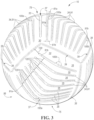
- the sports ball 10 of the present disclosure includes a plurality of outer panels that each have an undulating or wave-like topographical surface design or texture.
- the undulating or wave-like topographical design is formed via indentations having a greater width to depth aspect ratio than that of a bounding seam or pseudo seam. Such a configuration has been found to provide aerodynamic consistency that is improved from conventional designs.
- the sports ball 10 may be an inflatable sports ball such as a soccer ball or the like or a non-inflatable sports ball 10 such as a softball or the like.
- a sports ball 10 having the general configuration of a soccer ball is depicted in FIGS. 1-3 .
- the sports ball 10 may have a layered structure including a cover 12 and an interior 16 ( FIGS. 2 and 5-7 ).
- the cover 12 forms an exterior portion of the sports ball 10.
- the interior 16 forms an interior portion of sports ball 10.
- the interior 16 may be one of a solid mass and a hollow mass, fixed in size.
- the interior 16 may be an interior bladder ( FIG. 2 and 6 ).
- the interior 16 in order to facilitate inflation (i.e., fill the interior with pressurized air), the interior 16 generally includes a valved opening 17 that extends through the cover 12, thereby being accessible from the exterior surface 13 of the sports ball 10.
- the bladder 16 Upon inflation, the bladder 16 is pressurized and the pressurization induces the exterior surface 13 to be a substantially spherical surface as the sports ball 10 takes on a substantially spherical shape. More particularly, pressure within the bladder 16 causes the bladder 16 to place an outward force upon the cover 12 on an inner substrate surface 20.
- the cover 12 forms an exterior portion of the sports ball 10 and defines an exterior surface 13.
- the term cover 12 is meant to include any layer of the sports ball 10 that surrounds the interior 16.
- the cover 12 has a thickness 88 and may include both the outermost layer and also any intermediate layers, which are disposed between the interior 16 and the exterior surface 13.
- the cover 12 may be composed as a layered structure including an outer substrate layer 24 and an intermediate structure 14 located interior to the outer substrate layer 24 between the outer substrate layer 24 and the interior 16.
- the outer substrate layer 24 defines an outer substrate surface 18.
- the inner substrate surface 20 is disposed opposite the outer substrate surface 18, and may be disposed adjacent to the ball interior 16.
- the outer substrate layer 24 may be composed of a polymeric material, a polymer foam material, or the like.
- suitable polymer materials include, but are not limited to, polyurethane, polyvinylchloride, polyamide, polyester, polypropylene, polyolefin, and the like.
- the intermediate structure 14 may include a first intermediate cover layer 26 and a second intermediate cover layer 22.
- the first intermediate cover layer 26 is positioned between the outer substrate layer 24 and the second intermediate cover layer 22.
- the second intermediate cover layer 22 is positioned between the first intermediate cover layer 26 and the interior bladder 16.
- the second intermediate cover layer 22 may include the inner substrate surface 20, wherein the inner substrate surface 20 is positioned adjacent to the ball interior 16.
- the respective cover layers 22, 26 of the intermediate structure 14 may be composed of a polymeric material, a polymer foam material, a foam material, textiles, or the like.
- suitable polymer materials include, but are not limited to, polyurethane, polyvinylchloride, polyamide, polyester, polypropylene, polyolefin, and the like.
- suitable polymer foam materials include, but are not limited to, polyurethane, ethylvinylacetate, and the like.
- suitable textile materials include, but are not limited to, a woven or knit textile formed from polyester, cotton, nylon, rayon, silk, spandex, or a variety of other materials.
- a textile material may also include multiple materials, such as a polyester and cotton blend.
- the intermediate structure 14 may further provide a softened feel to the sports ball, impart energy return, and restrict expansion of bladder 16, in an inflatable sports ball 10 example.
- the outer substrate layer 24 may be formed of a thermoplastic polyurethane material (TPU)
- the first intermediate cover layer 26 may be formed from a polymer foam material
- the second intermediate cover layer 22 may be formed from a textile material.
- the cover may further include an external surface layer 25 disposed upon the outer substrate surface 18 of the cover 12.
- the external surface layer 25 may be a film that includes a pigment or a graphic thereon.
- the external surface layer 25 may also be an outer film or a clear coat having weather resistant properties.
- the external surface layer 25 may be a polyurethane film or the like.
- the external surface layer 25 may be bonded to the outer substrate surface 18 via a bonding material.
- the cover 12 may be generally formed by a plurality of adjoining panels 28, wherein each panel 28 has a respective panel surface that defines a portion of the outer substrate surface 18.
- the plurality of panels 28 includes at least a first panel 30 having a first panel surface and a second panel 32 having a second panel surface.
- the plurality of panels 28 may comprise the conventional twelve (12) panels or any other number of panels 28, for example, four joined panels 28 each having nine edges 36 and having a generally triangular shape that is formed from three pentagons.
- the cover 12 may also exhibit a substantially uniform or unbroken configuration that does not include panels 28 joined at abutting edge areas 36 via seams 38, or includes fewer panels 28.
- Each panel 28 may have a panel center 37 and a panel limit 39, wherein the panel limit 39 runs adjacent the abutting edge areas 36.
- the cover 12 may further define a first plurality of indentations 38 and a second plurality of indentations 34.
- the exterior surface 13 may define a plurality of plateau sections 35 disposed between the indentations 34, 38. More particularly, the plurality of plateau sections 35, the first plurality of indentations 38, and second plurality of indentations 34 are positioned on the respective panel 28, such that the plurality of plateaus 35, the first plurality of indentations 38, and second plurality of indentations 34 define a surface profile 45 that includes an alternating and repeating series of plateaus and indentations 34, 38.
- the plurality of plateaus 35, the first plurality of indentations 38, and second plurality of indentations 34 cooperate to define a topographical arrangement 56 across the exterior surface 13 of the cover 12.
- the topographical design 56 may be composed of a plurality of predefined panel arrangements, wherein a predefined panel arrangement 75 is defined as the orientation of the plateaus 35 and indentations 34, 38 on each of the respective panels 28.
- Each predefined panel arrangement 75 may be comprised a plurality of subpanel arrangements 73, 77, 79.
- the first plurality of indentations 38 may have a first indentation terminus 63 radially-spaced apart from the outer substrate surface 18 in a direction toward the inner substrate surface 20. Further, each of the first plurality of indentations 38 has a first indentation depth 41 and a first indentation width 43. The first indentation terminus 63 is radially-spaced apart from the outer substrate surface 18 by the first indentation depth 41. Accordingly, each of the first plurality of indentations 38 may have a first maximum aspect ratio. The first maximum aspect ratio is defined as the ratio of the first indentation width 43 to the first indentation depth 41.
- the first plurality of indentations 38 may be defined as a plurality of seams 38 configured to couple the plurality of panels 28.
- the respective panels 28 may be adjoined together along abutting edge areas 36 ( FIG. 4 ) via at least one seam 38 ( FIGS. 1-3 and 7 ).
- the panels 28 may be coupled along the abutting edge areas 36 by the seam 38 with stitching, bonding, welding, adhesives, or another suitable coupling method.
- stitching or variants thereof (such as “thermal bonding") is defined as a technique for securing two elements to one another that involves a softening or melting of a polymer material within at least one of the elements such that the materials of the elements are secured to each other when cooled.
- welded or variants thereof (e.g., "thermal bond”) is defined as the bond, link, or structure that joins two elements through a process that involves a softening or melting of a polymer material within at least one of the elements such that the materials of the elements are secured to each other when cooled.
- An example of welded seams 38 is disclosed in U.S. Patent No. 8,608,599 to Raynak, et al
- U.S. Patent No. 8,608,599 to Raynak, et al. generally discloses examples of welded seams, in that welding generally produces a heat affected zone in which the materials of the two joined components are intermingled.
- This heat affected zone may be considered a "weld” or "thermal bond.”
- welding may involve (a) the melting or softening of two panels that include polymer materials such that the polymer materials from each panel intermingle with each other (e.g., diffuse across a boundary layer between the polymer materials) and are secured together when cooled, as well as (b) the melting or softening a polymer material in a first panel such that the polymer material extends into or infiltrates the structure of a second panel (e.g., infiltrates crevices or cavities formed in the second panel or extends around or bonds with filaments or fibers in the second panel) to secure the panels together when cooled.
- welding may occur when only one panel includes a polymer material or when both panels include polymer materials.
- each seam 38 may have a seam maximum aspect ratio being defined as the ratio of the seam width 43 to the seam depth 41.
- the seam depth may be greater than 0.5 millimeters, more particularly the seam depth 41 may be from about 0.5 millimeters to about 0.75 millimeters.
- the seam width 43 may be from about 0.5 centimeters to about 0.65 centimeters.
- the first plurality of indentations 38 may be defined as debossed features, such as pseudo seams 33.
- the pseudo seams may be positioned in areas of the cover 12 that correspond with the positions of seams 38 in a conventional twelve panel or four panel sports ball 10, in order to impart the appearance of seams 38, when the cover 12 has a substantially uniform or unbroken configuration that does not include panels 28 or includes fewer panels 28.
- the pseudo seams 33 may be positioned in areas of the cover 12 that correspond with the positions of seams 38 in a conventional twelve panel or four panel sports ball 10, in order to impart the appearance of seams 38, when the cover 12 has a substantially uniform or unbroken configuration that does not include panels 28 or includes fewer panels 28.
- the pseudo seams 33 may also be positioned in other areas of the cover 12 that do not correspond with the positions of seams 38 in a conventional twelve panel or four panel sports ball 10, such as interior portions of the respective panels 28, as shown by example in FIGS. 3-4 .
- the first indentation width 43 is a pseudo seam width
- the first indentation depth 41 is a pseudo seam depth.
- each pseudo seam 33 may have a pseudo seam maximum aspect ratio.
- the pseudo seam maximum aspect ratio may be defined as the ratio of the pseudo seam width 43 to the pseudo seam depth 41.
- the pseudo seam 33 may have substantially similar dimensions to that of a conventional seam 38, wherein the pseudo seam width is substantially similar to the seam width and wherein the pseudo seam depth is substantially similar to the seam depth.
- the pseudo seam depth may be greater than 0.5 millimeters, more particularly the pseudo seam depth may be from about 0.5 millimeters to about 0.75 millimeters.
- the pseudo seam width may be from about 0.5 centimeters to about 0.65 centimeters.
- first plurality of indentations including any seams 38 and pseudo seams 33 may further define a first aggregate deboss length.
- the first aggregate deboss length is defined as a sum of all of the seam lengths and all of the pseudo seam lengths.
- the first aggregate deboss length may be from about 135 centimeters to about 150 centimeters.
- the first aggregate deboss length may be from about 140 centimeters to about 145 centimeters. More particularly, the first aggregate deboss length shown in the example of FIGS. 3 and 4 may be about 142 centimeters.
- each of the second plurality of indentations 34 may have a second indentation terminus 65 radially-spaced apart from the outer substrate surface 18 in a direction toward the inner substrate surface 20. Further, each of the second plurality of indentations 34 has a second indentation depth 67 and a second indentation width 61. The second indentation terminus 65 is radially-spaced apart from the outer substrate surface 18 by the second indentation depth 67.
- the second plurality of indentations 34 is defined as a plurality of channels.
- the channels 34 may be spaced apart from the seams 38 of the sports ball 10.
- the channels 34 may extend to edges 36 of the panels 28 and, thus, continue across a respective seam 38. More particularly, a channel 34 on the first panel 30 and a channel 34 on the second panel 32 may be in substantial alignment with one another across a respective seam 38. This may also enable patterns, arrangements, or other designs to be carried across multiple panels, bridging seams 38 between the panels 28.
- Channels 34 may impart various advantages to ball 10. For example, channels 34 may enhance the aerodynamics of ball 10, provide a greater amount of consistency or control over ball 10 during play, e.g., during kicking, dribbling, or passing, improve ball feel, and provide for water channeling.
- Channels 34 may be formed in the cover 12 via a variety of manufacturing processes including, but not limited to, debossing. Examples of a manufacturing process for forming channels 34 are disclosed in U.S. Patent No. 9,370,693 to Berggren, et al. U.S. Patent No. 9,370,693 to Berggren, et al. generally discloses a variety of manufacturing processes that may be utilized to form debossed features in the panels.
- one of the panels is located on a platen.
- a press plate is positioned above the platen and includes a protrusion having a predetermined shape. The protrusion presses into and heats the areas of the panel forming the debossed features. The press plate then moves away from the panel to substantially complete the formation of the debossed feature.
- each channel 34 has a channel terminus 65 that is radially-spaced apart from the outer substrate surface 18 in a direction toward the inner substrate surface 20. Further, each channel 34 has a channel depth 67 and a channel width 61. The channel terminus 65 is radially-spaced apart from the outer substrate surface 18 the channel depth 67. Accordingly, each channel 34 may have a channel maximum aspect ratio.
- the channel maximum aspect ratio is defined as the ratio of the maximum channel width 61a ( FIG. 3 ) to the channel depth 67.
- the channel maximum aspect ratio is equal to the second maximum aspect ratio.
- channels 34 are formed in the cover 12 and extend toward the interior 16.
- the intermediate structure 14 is positioned between outer substrate layer 24 and the interior bladder 16.
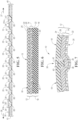
- the outer substrate layer 24 may be bonded to the intermediate structure 14 at the respective channel 34. More particularly, the outer substrate layer 24 may be welded directly to the second intermediate cover layer 22 at the channel terminus 65 of the respective channel 34 ( FIGS. 8A-C and 8E-G ), such that the outer substrate layer 24 extends through an entirety of the channel depth 67 at each channel 34.
- the channel 34 may include an exterior indentation 82 and an interior indentation 84.
- the exterior indentation 82 has the terminus 65 that is radially-spaced apart from the outer substrate surface 18 by the channel depth 67.
- the exterior and interior indentations 82 and 84 may have a generally rounded configuration. As depicted in FIG. 8A the exterior and interior indentations 82 and 84 extend to an approximate midpoint of the thickness 88 of the panel cross-section. In another configuration, as depicted in FIGS. 8B and 8C , the exterior indentation 82 extends through more of the thickness 88 of panel cross section than the interior indentation 84. In yet another configuration, as depicted in FIG. 8C , the exterior indentation 82 extends through substantially all of the thickness 88 of panel cross-section. As also shown in FIG.
- the second intermediate cover layer 22 may have a substantially planar configuration opposite the exterior indentation 82. Said another way, in some embodiments, the channel 34 may have only an exterior indentation 82 and no interior indentation 84.
- indentations 82 and 84, as well as the outer substrate layer 24 and the second intermediate cover layer 22, may be spaced from each other, such that a portion of the first intermediate cover layer 26 extends between indentations 82 and 84 and between the outer substrate layer 24 and the second intermediate cover layer 22.
- the outer substrate layer 24 is bonded to the first intermediate cover layer 26 at the channel 34.
- the first intermediate cover layer 26 has a first thickness 90 between indentations 82 and 84 and at the terminus 65 of the exterior indentation 82.
- the first intermediate cover layer 26 has a second thickness 99 between the outer substrate layer 24 and the second intermediate cover layer 22, in an area spaced apart from indentations 82 and 84 and the terminus 65 of the exterior indentation 82, e.g., at a plateau 35. As shown in FIG. 8D , the first thickness 90 is less than the second thickness 99.
- the channels 34 may include an exterior indentation 82 and an interior indentation 84 that exhibit substantially squared configurations ( FIGS. 8E-8G ).
- the indentations 82, 84 may have substantially squared cross-sectional configurations. Such substantially squared cross-sectional configurations may have a more distinct appearance than indentations 82, 84 having substantially rounded cross-sectional configurations.
- substantially squared indentations 82, 84 may also provide performance benefits such as aerodynamics, ball feel, and water channeling.
- the exterior indentation 82 and interior indentation 84 are two opposing indentations having substantially squared cross-sectional configurations.
- the indentations 82 and 84 extend to an approximate midpoint of the thickness 88 of the panel cross-section, such that the terminus 65 of the exterior indentation 82 is positioned radially inward from the exterior surface 13 to the approximate midpoint of the thickness 88 of the panel cross-section.
- the exterior indentation 82 may extend through substantially the entirety of the thickness 88 of the panel cross section.
- second intermediate cover layer 22 may have a substantially planar configuration opposite the exterior indentation 82.
- the channel 34 may have only an exterior indentation 82 and no interior indentation 84.
- the debossed feature 34 may include substantially-squared exterior indentation 82 having a rounded shoulder portion 29.
- a substantially-squared shoulder portion 29 may have a minimal radius, as shown in FIG. 8F .
- a rounded shoulder portion 29 having a larger radius may be used, as shown in FIG. 8G .
- the second plurality of indentations, i.e., the channels 34 may further define a second aggregate deboss length.
- the second aggregate deboss length is defined as a sum of all of the channel lengths.
- the second aggregate deboss length may be greater than 800 centimeters. More particularly, the second aggregate deboss length may be from about 850 centimeters to about 1050 centimeters. In the example shown in FIGS. 3 and 4 the second aggregate deboss length may be about 950 centimeters.
- the sports ball 10 may further have an aggregate feature length, which is defined as the sum of the first aggregate deboss length (total length of all the first plurality of indentations, e.g., the seams 38 and pseudo seams 33) and the second aggregate deboss length (total length of all channels 34).
- the aggregate feature length may be greater than 800 centimeters.
- the aggregate feature length is from about 1000 centimeters to about 1200 centimeters, wherein the first plurality of indentations 33, 38 and the second plurality of indentations 34 cooperate to cover approximately 55% - 70% of the exterior surface 13 of the cover 12.
- Increased aggregate feature length and increased surface coverage of the exterior surface by the indentations 33, 34, 38 creates positive flight characteristics (consistency and length of trajectory) and enhances the aerodynamics of ball 10, i.e., reducing aerodynamic drag on the ball for better accuracy, consistency, and increased velocity. Due to increased aggregate feature length and increased surface coverage of the exterior surface 13 by the indentations 33, 34, 38, it is more likely that the boundary layer of air surrounding the of the sports ball 10 in flight will undergo the transition from laminar to turbulent flow, resulting in enhanced flight characteristics and aerodynamic properties.
- acceptable minimum predefined distances 120 between indentations to maintain desired softness and ball feel characteristics may be greater than 9.0 millimeters.
- each channel 34 comprises a first boundary 87 and a second boundary 89, such that the second indentation width 61 is disposed between the first boundary 87 and the second boundary 89.
- Each of the first boundary 87 and the second boundary 89 of the respective channel 34 border plateau sections 35.
- each channel 34 is formed as a chevron element 91.
- the chevron element 91 includes a first section 93 and a second section 94, each disposed between the respective first boundary 87 and second boundary 89.
- the first section 93 has a first section central end 92 and a first section distal end 95.
- the second section 94 has a second section central end 96 and a second section distal end 97.
- the first section central end 92 is connected to the second section central end 96 at a chevron angle 100.
- the chevron angle 100 is less than 180 degrees. More particularly, the chevron angle 100 is greater than 90 degrees and less than 180 degrees. Accordingly, the first section 93 is obliquely angled with respect to the second section 94.
- the channel width 61 may be variable between the first section central end 92 and the first section distal end 95. Further the channel width 61 may be variable between the second section central end 96 and the second section distal end 97. Accordingly, the channel width 61 may be expressed as a first channel width 61a (the maximum channel width) measured at the chevron angle 100 of the respective channel 34 and a second channel width 61b measured at the distal ends 95, 97 of the first section 93 and the second section 94 of the respective chevron element 91. As shown in FIGS.
- the first channel width 61a (the maximum channel width) measured at the chevron angle 100 is greater than the second channel width 61b measured at the respective distal ends 95, 97 of the first section 93 and the second section 94.
- the first channel width 61a may be greater than 0.8 centimeters and the channel depth 67 may be greater than 0.7 millimeters.
- the first channel width 61a may be from about 0.8 centimeters to about 0.95 centimeters, and the channel depth may be from about 0.7 millimeters to about 1.0 millimeters.
- the channel may have a channel cross-sectional area of from about 2.9 square millimeters to about 3.0 square millimeters at the chevron angle 100.
- the second maximum aspect ratio is defined as the ratio of the second indentation width 61 to the second indentation depth 67 measured at the chevron angle 100. Said another way, the second maximum aspect ratio is a channel aspect ratio. The second maximum aspect ratio or channel aspect ratio is always greater than the first maximum aspect ratio or the maximum seam aspect ratio.
- the channel aspect ratio may be variable between the first section central end 92 and the first section distal end 95. Further the channel aspect ratio may be variable between the second section central end 96 and the first section distal end 95.
- the maximum channel aspect ratio is further defined as the ratio of the first channel width 61a and the channel depth 67 measured at the chevron angle 100.
- the channel minimum aspect ratio is further defined as the ratio of the second channel width 61b to the channel depth 67 measured at the distal ends 95, 97 of the first section 93 and second section 94 of the respective chevron element 91.
- the maximum channel aspect ratio is greater than the minimum channel aspect ratio.
- the minimum channel aspect ratio may be greater than the first maximum aspect ratio or seam aspect ratio, as shown in FIGS. 3-7 .
- the chevron-shaped 91 channels 34 and the plateau sections 35 cooperate to define topographical arrangement 56 across a majority of the exterior surface 13 of the cover 12.
- the example topographical design 56 shown in FIG. 3 promotes a balanced design across the exterior surface 13 ball 10.
- a balanced topographical design 56 avoids uneven lift of the ball 10 and improves consistency of the ball 10 when kicked in any orientation.
- Ball 10 consistency is one property that is often commented on by players. The most consistent balls are the ones with the optimum combination of amplitude and frequency of the varying force coefficients relative to the amount of spin. As such, the tailoring of the topographical design 56 on the ball 10 may allow for optimization of consistency and improved aerodynamics.
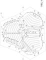
- the topographical design 56 may be composed of a plurality of predefined panel arrangements, wherein a predefined panel arrangement 75 is defined as the orientation of the plateaus 35 and chevron elements 91 on each of the respective panels 28. Each predefined panel arrangement 75 may be comprised a plurality of subpanel arrangements 73, 77, 79.
- the topographical design 56 is composed of a plurality of panels 28, namely, four panels, each having the same predefined panel arrangement 75.
- the predefined panel arrangement 75 is composed of three substantially similar subpanel arrangements 73, 77, 79. Each subpanel arrangement 73, 77, 79 of the example four panel ball 10 would correspond to a single predefined panel arrangement 75 on a conventional twelve panel ball 10.
- Each subpanel arrangement 73, 77, 79 includes the chevron elements 91 of the plurality of channels 34 and alternating plateau sections 35. As shown in FIGS. 3 and 4 , the respective subpanel arrangements 73, 77, 79 comprise an alternating and repeating series of plateaus 35 and chevron elements 91 extending between the panel center 37 and the panel limit 39.
- Each respective subpanel arrangement 73, 77, 79 includes a first chevron element 91a having a first chevron angle 100a.
- the first chevron element 91a is proximate to the panel center 37.
- Each respective subpanel arrangement 73, 77, 79 may further include at least a second chevron element 91b having a second chevron angle 100b.
- the second chevron element 91b is proximate to the panel limit 39, as shown in FIG. 4 .
- the chevron angle 100 is always less than 180 degrees, the chevron angle 100 gets larger or more obtuse as the chevron elements 91 move from the panel center 37 to the panel limit 39.
- the first chevron angle 100a is more acute than the second chevron angle 100b.
- the first chevron angle 100a is smaller than the second chevron angle 100b.
- the respective subpanel arrangements 73, 77, 79 may comprise from about seven plateau sections 35 and six corresponding chevron-shaped 91 channels 34 to about eleven plateau sections 35 and ten corresponding chevron-shaped 91 channels 34.
- the respective subpanel arrangements 73, 77, and 79 comprise an alternating and repeating series of nine plateau sections 35 and eight chevron-shaped 91 channels 34.
Landscapes
- Health & Medical Sciences (AREA)
- General Health & Medical Sciences (AREA)
- Physical Education & Sports Medicine (AREA)
- Professional, Industrial, Or Sporting Protective Garments (AREA)
Claims (15)
- Ballon de sport (10) gonflable comprenant :une vessie intérieure ;une enveloppe (12) disposée autour de la vessie intérieure, l'enveloppe comprenant une pluralité de panneaux contigus (28) et définissant :une surface extérieure (13) ;une première pluralité d'indentations (38) présentant une première profondeur d'indentation, une première largeur d'indentation (43) et un premier rapport d'aspect maximum, dans lequel le premier rapport d'aspect maximum est défini en tant qu'un rapport entre la première largeur d'indentation (43) et la première profondeur d'indentation ;une deuxième pluralité d'indentations (34) présentant une deuxième profondeur d'indentation, une deuxième largeur d'indentation (61) et un deuxième rapport d'aspect maximum, dans lequel le deuxième rapport d'aspect maximum est défini comme un rapport entre la deuxième largeur d'indentation (61) et la deuxième profondeur d'indentation ; etdans lequel le deuxième rapport d'aspect maximum est plus grand que le premier rapport d'aspect maximum, etcaractérisé en ce quela deuxième pluralité d'indentations (34) est une pluralité de canaux (34) et chacun des canaux (34) comprend un élément de chevron (91), dans lequel l'élément de chevron (91) comporte :une première section (93) présentant une première extrémité centrale de section (92) et une première extrémité distale de section (95) ;une deuxième section (94) présentant une deuxième extrémité centrale de section (96) et une deuxième extrémité distale de section (97) ; etdans lequel la première extrémité centrale de section (92) est reliée à la deuxième extrémité centrale de section (96) à un angle de chevron (100) et dans lequel la première section (93) forme un angle à l'oblique par rapport à la deuxième section.
- Ballon de sport (10) gonflable selon la revendication 1, dans lequel :la première largeur d'indentation (43) va d'environ 0,5 cm à environ 0,65 cm etla première profondeur d'indentation va d'environ 0,5 mm à environ 0,75 mm ; etla deuxième largeur d'indentation (61) va d'environ 0,8 cm à environ 0,95 cm et la deuxième largeur d'indentation va d'environ 0,7 mm à environ 1,0 mm.
- Ballon de sport (10) gonflable selon la revendication 2, dans lequel la première pluralité d'indentations (38) définit une première longueur de bossage en relief et la deuxième pluralité d'indentations (34) définit une deuxième longueur de bossage en relief ; etdans lequel la première longueur de bossage en relief va d'environ 135 cm à environ 150 cm, et la deuxième longueur de bossage en relief va d'environ 850 cm à environ 1050 cm, et en option,dans lequel la première longueur de bossage en relief va d'environ 140 cm à environ 145 cm, et la deuxième longueur de bossage en relief est d'environ 950 cm, et en option,dans lequel la première pluralité d'indentations (38) et la deuxième pluralité d'indentations (34) définissent en outre une longueur de caractéristique en relief, dans lequel la longueur de caractéristique en relief est définie comme une somme de la première longueur de bossage en relief et de la deuxième longueur de bossage en relief ; etdans lequel la longueur de caractéristique en relief est supérieure à 1000 cm, et en option,dans lequel la première pluralité d'indentations (38) et la deuxième pluralité d'indentations (34) coopèrent pour définir d'environ 55 % à environ 70 % de la surface extérieure (13) de l'enveloppe (12).
- Ballon de sport (10) gonflable selon la revendication 1,dans lequel chacun des canaux (34) est espacé de chacun des autres canaux (34) et de chacune de la première pluralité d'indentations (38) d'une distance prédéfinie minimum, etdans lequel la distance prédéfinie minimum est supérieure à 9,0 mm, et en option,dans lequel chaque canal (34) comprend une première limite (87) et une deuxième limite (89) de telle sorte que la deuxième largeur d'indentation (61) est disposée entre la première limite (87) et la deuxième limite (89).
- Ballon de sport (10) gonflable selon la revendication 4, dans lequel l'angle de chevron (100) est inférieur à 180 degrés, et en option,
dans lequel l'angle de chevron (100) est supérieur à 90 degrés. - Ballon de sport gonflable selon la revendication 5, dans lequel :la deuxième profondeur d'indentation est définie comme une profondeur de canal (67) ;la deuxième largeur d'indentation (61) est définie comme une première largeur de canal (61a) à l'angle de chevron (100) ;la deuxième largeur d'indentation (61) est définie comme une deuxième largeur de canal (61b) sur l'extrémité distale (95) de la première section (93) et l'extrémité distale (97) de la deuxième section (94) de l'élément de chevron (91a, 91b) respectif ; etla première largeur de canal (61a) est supérieure à la deuxième largeur de canal (61b), eten option,dans lequel le deuxième rapport d'aspect maximum est défini comme un rapport entre la première largeur de canal (61a) et la profondeur de canal (67) mesurée à l'angle de chevron (100), et en option,dans lequel chaque canal (34) présente un rapport d'aspect minimum défini en tant que le rapport entre la deuxième largeur de canal (61b) et la profondeur de canal (67) mesurée sur l'extrémité distale (95) de la première section (93) et l'extrémité distale (97) de la deuxième section (94) de l'élément de chevron (91a, 91b) respectif.
- Ballon de sport (10) gonflable selon la revendication 6, dans lequel le deuxième rapport d'aspect maximum est supérieur au rapport d'aspect minimum de chaque canal.
- Ballon de sport (10) gonflable selon la revendication 7, dans lequel la première pluralité d'indentations (38) est définie comme une pluralité de pseudo coutures (38), ou en option,
dans lequel la première pluralité d'indentations (38) est définie comme une pluralité de coutures (38) configurées pour joindre la pluralité de panneaux contigus (28). - Ballon de sport (10) gonflable selon la revendication 7, dans lequel :les éléments de chevron (91) sont disposés dans un agencement de panneaux prédéfini sur chacun des panneaux (28) respectifs et chaque agencement de panneaux prédéfini comprend une pluralité d'agencements de sous-panneaux ; etchaque agencement de sous-panneaux comporte une pluralité de plateaux disposés entre les éléments de chevron (91), dans lequel les plateaux et les éléments de chevrons (91) forment une série alternée et récurrente des plateaux et des éléments de chevron (91) s'étendant depuis un centre de panneau à une limite de panneau, et en option, dans lequel :les séries répétées et récurrentes de plateaux et d'éléments de chevron comportent un premier élément de chevron (91a) à proximité du centre de panneau présentant un premier angle de chevron (100a) et un deuxième élément de chevron (91b) à proximité de la limite de panneau présentant un deuxième angle de chevron (100b) ; etle premier angle de chevron (100a) est plus aigu que le deuxième angle de chevron (100b).
- Ballon de sport (10) gonflable selon la revendication 1, dans lequel :la première pluralité d'indentations (38) est une pluralité de coutures (38) périphériques entre des panneaux contigus de la pluralité de panneaux, chaque couture présentant une terminaison de couture espacée radialement de la surface extérieure par une profondeur de couture, une largeur de couture et un rapport d'aspect maximum de couture, dans lequel le rapport d'aspect maximum de couture est défini comme un rapport entre la largeur de couture et la profondeur de couture ;la pluralité de canaux (34) présente une terminaison de canal espacée radialement de la surface extérieure par une profondeur de canal (67), une largeur de canal (61), et un rapport d'aspect maximum de canal, dans lequel le rapport d'aspect maximum de canal est défini comme un rapport entre la largeur de canal (61) et la profondeur de canal (67) ; etdans lequel le rapport d'aspect maximum de canal est plus grand que le rapport d'aspect maximum de couture.
- Ballon de sport (10) gonflable selon la revendication 10, dans lequel l'angle de chevron (100) est inférieur à 180 degrés, et en option,
dans lequel l'angle de chevron (100) est supérieur à 90 degrés. - Ballon de sport gonflable selon la revendication 10, dans lequel le deuxième rapport d'aspect maximum est défini comme le rapport entre la largeur de canal (61) et la profondeur de canal (67) mesurée à l'angle de chevron (100), et en option,dans lequel la largeur de canal (61) va d'environ 0,8 cm à environ 0,95 cm,et en optiondans lequel la profondeur de canal (67) va d'environ 0,7 mm à environ 1,0 mm,et en optiondans lequel la largeur de couture va d'environ 0,5 cm à environ 0,65 cm, eten optiondans lequel la profondeur de couture va d'environ 0,5 mm à environ 0,75 mm.
- Ballon de sport (10) gonflable selon la revendication 12, dans lequel :la largeur de canal (61) est définie comme une première largeur de canal (61a) à l'angle de chevron (100) ;la largeur de canal (61) est définie comme une deuxième largeur de canal (61b) sur l'extrémité distale (95) de la première section (93) et l'extrémité distale (97) de la deuxième section (94) de l'élément de chevron (91a, 91b) respectif ; etla première largeur de canal (61a) est plus grande que la deuxième largeur de canal (61b), eten optiondans lequel le deuxième rapport d'aspect maximum est défini comme un rapport entre la première largeur de canal (61a) et la profondeur de canal (67) mesurée à l'angle de chevron (100), et en optiondans lequel chaque canal présente un rapport d'aspect minimum défini comme le rapport entre la deuxième largeur de canal (61b) et la profondeur de canal (67) mesurée sur une de l'extrémité distale (95) de la première section (93) et l'extrémité distale (97) de la deuxième section (94) de l'élément de chevron (91a, 91b) respectif ; etdans lequel le deuxième rapport d'aspect maximum est supérieur au rapport d'aspect minimum de chaque canal.
- Ballon de sport (10) gonflable selon la revendication 13, dans lequel :la surface extérieure (13) définit une pluralité de plateaux disposés entre les éléments de chevron (91) ;les éléments de chevron (91) et les plateaux sont disposés dans un agencement de panneaux prédéfini sur chacun des panneaux respectifs ; etchaque agencement de panneaux prédéfini est composé d'une pluralité d'agencements de sous-panneaux, dans lequel chaque agencement de sous-panneaux comporte une série alternée et récurrente des plateaux et des éléments de chevron (91) s'étendant depuis un centre de panneau à une limite de panneau.
- Ballon de sport (10) gonflable selon la revendication 14, dans lequel les séries alternées et récurrentes des plateaux et des éléments de chevron (91) comportent :un premier élément de chevron (91a) plus proche du centre de panneau que la limite de panneau et présentant un premier angle de chevron (100a) ; etun deuxième élément de chevron (91b) plus proche de la limite de panneau que le centre de panneau et présentant un deuxième angle de chevron (100), et en option,dans lequel le premier angle de chevron (100a) est plus aigu que le deuxième angle de chevron (100b).
Applications Claiming Priority (2)
| Application Number | Priority Date | Filing Date | Title |
|---|---|---|---|
| US201862725685P | 2018-08-31 | 2018-08-31 | |
| PCT/US2019/043630 WO2020046508A1 (fr) | 2018-08-31 | 2019-07-26 | Ballon de sport |
Publications (2)
| Publication Number | Publication Date |
|---|---|
| EP3843861A1 EP3843861A1 (fr) | 2021-07-07 |
| EP3843861B1 true EP3843861B1 (fr) | 2024-07-24 |
Family
ID=67544472
Family Applications (1)
| Application Number | Title | Priority Date | Filing Date |
|---|---|---|---|
| EP19750026.7A Active EP3843861B1 (fr) | 2018-08-31 | 2019-07-26 | Ballon de sport |
Country Status (3)
| Country | Link |
|---|---|
| US (1) | US11148013B2 (fr) |
| EP (1) | EP3843861B1 (fr) |
| WO (1) | WO2020046508A1 (fr) |
Families Citing this family (4)
| Publication number | Priority date | Publication date | Assignee | Title |
|---|---|---|---|---|
| US11173351B2 (en) * | 2018-08-31 | 2021-11-16 | Nike, Inc. | Sports ball |
| EP3843861B1 (fr) * | 2018-08-31 | 2024-07-24 | NIKE Innovate C.V. | Ballon de sport |
| US11148014B2 (en) * | 2019-01-18 | 2021-10-19 | Nike, Inc. | Sports ball |
| EP4106890A1 (fr) | 2020-02-21 | 2022-12-28 | NIKE Innovate C.V. | Ballon de sport avec éléments de surface à gradins |
Family Cites Families (96)
| Publication number | Priority date | Publication date | Assignee | Title |
|---|---|---|---|---|
| US1931429A (en) * | 1932-01-05 | 1933-10-17 | John L Buckner | Football |
| US2182052A (en) | 1937-11-30 | 1939-12-05 | Milton B Reach | Play or game ball |
| US2245115A (en) | 1938-04-23 | 1941-06-10 | Milton B Reach | Play or game ball |
| US2859040A (en) | 1952-09-10 | 1958-11-04 | Seamless Rubber Co | Football having a securely grippable laceless surface |
| US3512777A (en) | 1964-09-11 | 1970-05-19 | Voit Rubber Corp | Game ball |
| US4337944A (en) | 1979-04-12 | 1982-07-06 | Ideas That Sell, Inc. | Lighter and softer recreational balls |
| US4318544A (en) | 1980-10-30 | 1982-03-09 | W. H. Brine Company | Game ball |
| US4542902A (en) | 1984-03-15 | 1985-09-24 | Ideas That Sell, Inc. | Soccer ball and method of making same |
| US4736948A (en) | 1987-04-13 | 1988-04-12 | Thomas Milton L | Football |
| US4991842A (en) | 1989-09-08 | 1991-02-12 | Finley Charles O | Grip enhanced basketball |
| US4928962A (en) | 1989-09-08 | 1990-05-29 | Finley Charles O | Grip enhanced football |
| US5427372A (en) | 1993-07-01 | 1995-06-27 | Kransco | Applying patches and impressing patterns on ball |
| US5354053A (en) | 1993-07-01 | 1994-10-11 | Kransco | Play ball |
| USD357958S (en) | 1993-12-20 | 1995-05-02 | Audero Jr Jose C | Soccer ball |
| US5518234A (en) | 1994-05-03 | 1996-05-21 | Palmquist; Marvin E. | Game ball |
| US5451046A (en) | 1994-09-27 | 1995-09-19 | Batton; Rodney | Flag football equipment |
| US5683316A (en) | 1995-11-28 | 1997-11-04 | Campbell; Daniel Scott | Illuminated sports ball |
| US6012997A (en) | 1997-03-19 | 2000-01-11 | Mason; David W. | Compound safety ball |
| DE19720501A1 (de) | 1997-05-16 | 1998-11-19 | Wolfgang Ihde | System zur Vereinfachung der Herstellung von halbregulären Polyedern |
| US5851161A (en) | 1997-07-15 | 1998-12-22 | Sassak; Mark S. | Grippable surface for throwable objects |
| US6302815B1 (en) | 1997-09-22 | 2001-10-16 | Molten Corporation | Ball for a ball game |
| US5931752A (en) * | 1998-01-15 | 1999-08-03 | Wilson Sporting Goods Co. | Inflatable game ball with laid-in channel or logo |
| USD408876S (en) | 1998-02-06 | 1999-04-27 | Lisco, Inc. | Basketball |
| US6283881B1 (en) | 1998-02-06 | 2001-09-04 | Spalding Sports Worldwide, Inc. | Game ball |
| TW407060B (en) | 1998-05-22 | 2000-10-01 | Molten Corp | Ball for ball game |
| US6422961B1 (en) * | 1999-01-25 | 2002-07-23 | Spalding Sports Worldwide, Inc. | Rubber basketball with skived channel look |
| US6406389B1 (en) * | 1999-02-19 | 2002-06-18 | Spalding Sports Worldwide, Inc | Basketball having a carcass with seam areas |
| GB0109650D0 (en) * | 2001-04-19 | 2001-06-13 | Mitre Sports Internat Ltd | Game balls |
| US7300357B2 (en) | 2002-02-23 | 2007-11-27 | Breaker Richard C | Practice sport projectile having a through hole |
| US6988969B2 (en) | 2002-04-24 | 2006-01-24 | Nike, Inc. | Game ball with bridged panels |
| BR8300122U (pt) | 2003-01-20 | 2004-10-26 | Roberto Estefano | Disposição introduzida em bola esportiva |
| US7614959B1 (en) | 2003-11-18 | 2009-11-10 | Robert Gentile | High impact game ball construction method and device |
| WO2005097284A1 (fr) | 2004-03-26 | 2005-10-20 | Schneider Paul W | Dispositif de jouets volant de type bascule |
| WO2005115561A1 (fr) | 2004-05-17 | 2005-12-08 | Ricky Charles Pierce | Ballon d'entrainement au basket et ses procedes de production et d'utilisation |
| BE1016122A6 (nl) | 2004-07-16 | 2006-03-07 | Franck Jan | Nieuw type voetbal. |
| US20060105866A1 (en) | 2004-11-17 | 2006-05-18 | Hansan Ma | Football with a modified surface conferring altered aerodynamic properties |
| US20060205544A1 (en) | 2005-03-08 | 2006-09-14 | Polyworks, Inc. | Dynamic toy with inflatable bladder |
| US20060229150A1 (en) | 2005-04-11 | 2006-10-12 | Ou Tsung M | Lamination inflatable sports ball |
| US8002652B2 (en) | 2005-08-11 | 2011-08-23 | Wong Jacob Y | Sporting game of Sokker Golph™ |
| US20070117662A1 (en) | 2005-11-18 | 2007-05-24 | Hansan Ma | Dimpled soccer ball |
| US9452322B2 (en) * | 2006-08-02 | 2016-09-27 | Wislon Sporting Goods Co. | American football incorporating boundary layer trip mechanisms to reduce aerodynamic drag |
| US7585236B2 (en) * | 2006-08-02 | 2009-09-08 | Wilson Sporting Goods Co. | Game ball having optimally positioned grooves and/or ridges |
| US8251846B2 (en) * | 2006-08-02 | 2012-08-28 | Wilson Sporting Goods Co. | Game ball having optimally positioned grooves |
| GB2447845B (en) | 2007-03-28 | 2009-08-19 | Umbro Internat Ltd | Inflatable ball |
| US20090042659A1 (en) | 2007-04-02 | 2009-02-12 | Breaker Richard C | Practice sport projectile having a through-hole with transverse indicator |
| US8684870B2 (en) | 2007-04-12 | 2014-04-01 | Molten Corporation | Ball |
| US7854671B2 (en) | 2007-04-26 | 2010-12-21 | Haresh Lalvani | Sports ball |
| US20080287218A1 (en) | 2007-05-14 | 2008-11-20 | Lipose Corporation | Training balls for varying ball speed, methods of use, and systems |
| US8852039B2 (en) | 2011-06-28 | 2014-10-07 | Nike, Inc. | Sport ball casing with integrated bladder material |
| US8708847B2 (en) | 2008-06-27 | 2014-04-29 | Nike, Inc. | Sport ball casing and methods of manufacturing the casing |
| US8182379B2 (en) | 2008-06-27 | 2012-05-22 | Nike, Inc. | Sport balls and methods of manufacturing the sport balls |
| US8974330B2 (en) | 2009-03-20 | 2015-03-10 | Nike, Inc. | Sport ball casing and methods of manufacturing the casing |
| US8608599B2 (en) | 2009-03-20 | 2013-12-17 | Nike, Inc. | Sport ball casing and methods of manufacturing the casing |
| DE102009016287B3 (de) * | 2009-04-03 | 2010-11-04 | Adidas Ag | Ball |
| US8371971B2 (en) | 2009-04-10 | 2013-02-12 | Nike, Inc. | Football with aerodynamic lace |
| US20110012309A1 (en) | 2009-07-15 | 2011-01-20 | David Schreff | Aerodynamic sports toy, game and method of play |
| GB2485751A (en) | 2009-09-01 | 2012-05-23 | Victor Walling | Round ball,such as a soccer ball,having a pattern of fins to resist rolling |
| US8579743B2 (en) | 2010-01-05 | 2013-11-12 | Nike, Inc. | Sport balls and methods of manufacturing the sport balls |
| US20140179468A1 (en) | 2010-01-05 | 2014-06-26 | Nike, Inc. | Sport Balls Having Seam Reinforcing Strips |
| US20110250819A1 (en) | 2010-04-10 | 2011-10-13 | Daniel Francis Tashman | Interactive Toy |
| US9370693B2 (en) * | 2010-12-03 | 2016-06-21 | Nike, Inc. | Sport ball with indented casing |
| US8617011B2 (en) | 2010-12-03 | 2013-12-31 | Nike, Inc. | Sport ball with indented casing |
| US8602927B2 (en) * | 2010-12-29 | 2013-12-10 | Vertex L.L.C. | Game ball and method of manufacturing same |
| CN103608072A (zh) | 2011-02-15 | 2014-02-26 | 最佳点(Opoi)私人有限公司 | 运动训练器材 |
| JP5689339B2 (ja) | 2011-03-09 | 2015-03-25 | 株式会社ミカサ | 運動用ボール |
| US8597144B2 (en) | 2011-06-28 | 2013-12-03 | Nike, Inc. | Sport ball casing with thermoplastic reinforcing material |
| US9114286B2 (en) * | 2011-09-02 | 2015-08-25 | Wilson Sporting Goods Co. | Basketball having grooved seams |
| US8926459B2 (en) | 2012-03-30 | 2015-01-06 | Nike, Inc. | Sport balls and methods of manufacturing the sport balls |
| DE102013202485B4 (de) | 2013-02-15 | 2022-12-29 | Adidas Ag | Ball für eine Ballsportart |
| US9149701B1 (en) | 2013-03-15 | 2015-10-06 | Robin Bramlette | Training basketball |
| US9272190B2 (en) | 2013-12-24 | 2016-03-01 | Baden Sports, Inc. | Volleyball cover |
| US9486675B1 (en) | 2014-01-31 | 2016-11-08 | Nike, Inc. | Apparatus and method for manufacturing sport balls |
| US20150367183A1 (en) | 2014-06-23 | 2015-12-24 | Tsung Ming Ou | Method of Producing Sportsball with Sculptural Ball Surface |
| US20160082323A1 (en) | 2014-09-18 | 2016-03-24 | Stewart Higa | Floating soccer ball |
| DE102014219396A1 (de) | 2014-09-25 | 2016-03-31 | Adidas Ag | Herstellungsverfahren für eine äußere Schicht für ein Paneel eines Balls |
| AU2015365708A1 (en) | 2014-12-19 | 2017-08-10 | Mitre Sports International Limited | Sports balls |
| DE102015204151B4 (de) * | 2015-03-09 | 2025-12-24 | Adidas Ag | Ball, insbesondere Fußball, und Verfahren zur Herstellung eines Balls |
| DE102015209795B4 (de) | 2015-05-28 | 2024-03-21 | Adidas Ag | Ball und Verfahren zu dessen Herstellung |
| DE102015209797B3 (de) | 2015-05-28 | 2016-07-14 | Adidas Ag | Paneel für einen Ball |
| DE102015209800B4 (de) | 2015-05-28 | 2025-09-04 | Adidas Ag | Verfahren zur Herstellung eines dreidimensionalen Verbundgegenstands |
| US20170050089A1 (en) | 2015-08-17 | 2017-02-23 | 2nd Skull, LLC | Impact dissipating ball |
| USD786374S1 (en) | 2015-12-28 | 2017-05-09 | Nike, Inc. | Ball with surface ornamentation pattern |
| USD786375S1 (en) | 2015-12-28 | 2017-05-09 | Nike, Inc. | Ball with surface ornamentation pattern |
| WO2017176979A1 (fr) | 2016-04-06 | 2017-10-12 | Under Armour, Inc. | Ballon de sport |
| WO2018080912A1 (fr) * | 2016-10-24 | 2018-05-03 | Nike Innovate C.V. | Ballon de sport et enveloppe définissant un canal principal et un canal secondaire |
| US10201732B2 (en) | 2016-12-14 | 2019-02-12 | Mohammed Ejaz Ahmed | Ball with domed panels |
| US20180169483A1 (en) | 2016-12-19 | 2018-06-21 | Tsung Ming Ou | Sportsball with Sculptural Ball Surface |
| US10207158B2 (en) * | 2017-02-28 | 2019-02-19 | Nike, Inc. | Sports ball |
| US10350460B2 (en) | 2017-02-28 | 2019-07-16 | Nike, Inc. | Sports ball |
| US10258836B2 (en) * | 2017-05-25 | 2019-04-16 | Nike, Inc. | Sports ball with mechanoluminescence |
| USD863474S1 (en) | 2017-08-15 | 2019-10-15 | Nike, Inc. | Ball |
| USD863473S1 (en) | 2017-08-15 | 2019-10-15 | Nike, Inc. | Ball |
| US11173351B2 (en) * | 2018-08-31 | 2021-11-16 | Nike, Inc. | Sports ball |
| EP3843861B1 (fr) * | 2018-08-31 | 2024-07-24 | NIKE Innovate C.V. | Ballon de sport |
| WO2020112624A1 (fr) * | 2018-11-29 | 2020-06-04 | Nike Innovate C.V. | Balle de sport et procédé de fabrication |
| US11148014B2 (en) * | 2019-01-18 | 2021-10-19 | Nike, Inc. | Sports ball |
-
2019
- 2019-07-26 EP EP19750026.7A patent/EP3843861B1/fr active Active
- 2019-07-26 WO PCT/US2019/043630 patent/WO2020046508A1/fr not_active Ceased
- 2019-07-26 US US16/523,191 patent/US11148013B2/en active Active
Also Published As
| Publication number | Publication date |
|---|---|
| EP3843861A1 (fr) | 2021-07-07 |
| US11148013B2 (en) | 2021-10-19 |
| US20200070011A1 (en) | 2020-03-05 |
| WO2020046508A1 (fr) | 2020-03-05 |
Similar Documents
| Publication | Publication Date | Title |
|---|---|---|
| EP3911422B1 (fr) | Ballon de sport | |
| EP3843861B1 (fr) | Ballon de sport | |
| EP3843862B1 (fr) | Ballon de sport | |
| US10398944B2 (en) | Sport ball with indented casing | |
| EP2944359B1 (fr) | Ballon de sport à enveloppe dentelée | |
| US11202941B2 (en) | Sport ball and casing defining a major channel and a minor channel | |
| US20200171359A1 (en) | Sports ball and method of manufacture | |
| US11833397B2 (en) | Inflatable sports ball with restriction structure | |
| EP3993884B1 (fr) | Ballon de sport avec élément saillant | |
| US11759681B2 (en) | Sports ball with staggered surface features | |
| EP3708228B1 (fr) | Ballon de sport à enveloppe dentelée |
Legal Events
| Date | Code | Title | Description |
|---|---|---|---|
| STAA | Information on the status of an ep patent application or granted ep patent |
Free format text: STATUS: UNKNOWN |
|
| STAA | Information on the status of an ep patent application or granted ep patent |
Free format text: STATUS: THE INTERNATIONAL PUBLICATION HAS BEEN MADE |
|
| STAA | Information on the status of an ep patent application or granted ep patent |
Free format text: STATUS: REQUEST FOR EXAMINATION WAS MADE |
|
| PUAI | Public reference made under article 153(3) epc to a published international application that has entered the european phase |
Free format text: ORIGINAL CODE: 0009012 |
|
| 17P | Request for examination filed |
Effective date: 20210114 |
|
| AK | Designated contracting states |
Kind code of ref document: A1 Designated state(s): AL AT BE BG CH CY CZ DE DK EE ES FI FR GB GR HR HU IE IS IT LI LT LU LV MC MK MT NL NO PL PT RO RS SE SI SK SM TR |
|
| DAV | Request for validation of the european patent (deleted) | ||
| DAX | Request for extension of the european patent (deleted) | ||
| STAA | Information on the status of an ep patent application or granted ep patent |
Free format text: STATUS: EXAMINATION IS IN PROGRESS |
|
| 17Q | First examination report despatched |
Effective date: 20221219 |
|
| P01 | Opt-out of the competence of the unified patent court (upc) registered |
Effective date: 20230515 |
|
| GRAP | Despatch of communication of intention to grant a patent |
Free format text: ORIGINAL CODE: EPIDOSNIGR1 |
|
| STAA | Information on the status of an ep patent application or granted ep patent |
Free format text: STATUS: GRANT OF PATENT IS INTENDED |
|
| INTG | Intention to grant announced |
Effective date: 20240216 |
|
| GRAS | Grant fee paid |
Free format text: ORIGINAL CODE: EPIDOSNIGR3 |
|
| GRAA | (expected) grant |
Free format text: ORIGINAL CODE: 0009210 |
|
| STAA | Information on the status of an ep patent application or granted ep patent |
Free format text: STATUS: THE PATENT HAS BEEN GRANTED |
|
| AK | Designated contracting states |
Kind code of ref document: B1 Designated state(s): AL AT BE BG CH CY CZ DE DK EE ES FI FR GB GR HR HU IE IS IT LI LT LU LV MC MK MT NL NO PL PT RO RS SE SI SK SM TR |
|
| REG | Reference to a national code |
Ref country code: GB Ref legal event code: FG4D |
|
| REG | Reference to a national code |
Ref country code: CH Ref legal event code: EP |
|
| REG | Reference to a national code |
Ref country code: IE Ref legal event code: FG4D Ref country code: DE Ref legal event code: R096 Ref document number: 602019055715 Country of ref document: DE |
|
| REG | Reference to a national code |
Ref country code: LT Ref legal event code: MG9D |
|
| REG | Reference to a national code |
Ref country code: NL Ref legal event code: MP Effective date: 20240724 |
|
| PG25 | Lapsed in a contracting state [announced via postgrant information from national office to epo] |
Ref country code: PT Free format text: LAPSE BECAUSE OF FAILURE TO SUBMIT A TRANSLATION OF THE DESCRIPTION OR TO PAY THE FEE WITHIN THE PRESCRIBED TIME-LIMIT Effective date: 20241125 |
|
| REG | Reference to a national code |
Ref country code: AT Ref legal event code: MK05 Ref document number: 1705777 Country of ref document: AT Kind code of ref document: T Effective date: 20240724 |
|
| PG25 | Lapsed in a contracting state [announced via postgrant information from national office to epo] |
Ref country code: NL Free format text: LAPSE BECAUSE OF FAILURE TO SUBMIT A TRANSLATION OF THE DESCRIPTION OR TO PAY THE FEE WITHIN THE PRESCRIBED TIME-LIMIT Effective date: 20240724 |
|
| PG25 | Lapsed in a contracting state [announced via postgrant information from national office to epo] |
Ref country code: PT Free format text: LAPSE BECAUSE OF FAILURE TO SUBMIT A TRANSLATION OF THE DESCRIPTION OR TO PAY THE FEE WITHIN THE PRESCRIBED TIME-LIMIT Effective date: 20241125 Ref country code: NL Free format text: LAPSE BECAUSE OF FAILURE TO SUBMIT A TRANSLATION OF THE DESCRIPTION OR TO PAY THE FEE WITHIN THE PRESCRIBED TIME-LIMIT Effective date: 20240724 |
|
| PG25 | Lapsed in a contracting state [announced via postgrant information from national office to epo] |
Ref country code: NO Free format text: LAPSE BECAUSE OF FAILURE TO SUBMIT A TRANSLATION OF THE DESCRIPTION OR TO PAY THE FEE WITHIN THE PRESCRIBED TIME-LIMIT Effective date: 20241024 |
|
| PG25 | Lapsed in a contracting state [announced via postgrant information from national office to epo] |
Ref country code: GR Free format text: LAPSE BECAUSE OF FAILURE TO SUBMIT A TRANSLATION OF THE DESCRIPTION OR TO PAY THE FEE WITHIN THE PRESCRIBED TIME-LIMIT Effective date: 20241025 Ref country code: PL Free format text: LAPSE BECAUSE OF FAILURE TO SUBMIT A TRANSLATION OF THE DESCRIPTION OR TO PAY THE FEE WITHIN THE PRESCRIBED TIME-LIMIT Effective date: 20240724 Ref country code: FI Free format text: LAPSE BECAUSE OF FAILURE TO SUBMIT A TRANSLATION OF THE DESCRIPTION OR TO PAY THE FEE WITHIN THE PRESCRIBED TIME-LIMIT Effective date: 20240724 |
|
| PG25 | Lapsed in a contracting state [announced via postgrant information from national office to epo] |
Ref country code: BG Free format text: LAPSE BECAUSE OF FAILURE TO SUBMIT A TRANSLATION OF THE DESCRIPTION OR TO PAY THE FEE WITHIN THE PRESCRIBED TIME-LIMIT Effective date: 20240724 |
|
| PG25 | Lapsed in a contracting state [announced via postgrant information from national office to epo] |
Ref country code: LV Free format text: LAPSE BECAUSE OF FAILURE TO SUBMIT A TRANSLATION OF THE DESCRIPTION OR TO PAY THE FEE WITHIN THE PRESCRIBED TIME-LIMIT Effective date: 20240724 |
|
| PG25 | Lapsed in a contracting state [announced via postgrant information from national office to epo] |
Ref country code: IS Free format text: LAPSE BECAUSE OF FAILURE TO SUBMIT A TRANSLATION OF THE DESCRIPTION OR TO PAY THE FEE WITHIN THE PRESCRIBED TIME-LIMIT Effective date: 20241124 Ref country code: AT Free format text: LAPSE BECAUSE OF FAILURE TO SUBMIT A TRANSLATION OF THE DESCRIPTION OR TO PAY THE FEE WITHIN THE PRESCRIBED TIME-LIMIT Effective date: 20240724 |
|
| PG25 | Lapsed in a contracting state [announced via postgrant information from national office to epo] |
Ref country code: HR Free format text: LAPSE BECAUSE OF FAILURE TO SUBMIT A TRANSLATION OF THE DESCRIPTION OR TO PAY THE FEE WITHIN THE PRESCRIBED TIME-LIMIT Effective date: 20240724 |
|
| PG25 | Lapsed in a contracting state [announced via postgrant information from national office to epo] |
Ref country code: RS Free format text: LAPSE BECAUSE OF FAILURE TO SUBMIT A TRANSLATION OF THE DESCRIPTION OR TO PAY THE FEE WITHIN THE PRESCRIBED TIME-LIMIT Effective date: 20241024 Ref country code: ES Free format text: LAPSE BECAUSE OF FAILURE TO SUBMIT A TRANSLATION OF THE DESCRIPTION OR TO PAY THE FEE WITHIN THE PRESCRIBED TIME-LIMIT Effective date: 20240724 |
|
| PG25 | Lapsed in a contracting state [announced via postgrant information from national office to epo] |
Ref country code: RS Free format text: LAPSE BECAUSE OF FAILURE TO SUBMIT A TRANSLATION OF THE DESCRIPTION OR TO PAY THE FEE WITHIN THE PRESCRIBED TIME-LIMIT Effective date: 20241024 Ref country code: PL Free format text: LAPSE BECAUSE OF FAILURE TO SUBMIT A TRANSLATION OF THE DESCRIPTION OR TO PAY THE FEE WITHIN THE PRESCRIBED TIME-LIMIT Effective date: 20240724 Ref country code: NO Free format text: LAPSE BECAUSE OF FAILURE TO SUBMIT A TRANSLATION OF THE DESCRIPTION OR TO PAY THE FEE WITHIN THE PRESCRIBED TIME-LIMIT Effective date: 20241024 Ref country code: LV Free format text: LAPSE BECAUSE OF FAILURE TO SUBMIT A TRANSLATION OF THE DESCRIPTION OR TO PAY THE FEE WITHIN THE PRESCRIBED TIME-LIMIT Effective date: 20240724 Ref country code: IS Free format text: LAPSE BECAUSE OF FAILURE TO SUBMIT A TRANSLATION OF THE DESCRIPTION OR TO PAY THE FEE WITHIN THE PRESCRIBED TIME-LIMIT Effective date: 20241124 Ref country code: HR Free format text: LAPSE BECAUSE OF FAILURE TO SUBMIT A TRANSLATION OF THE DESCRIPTION OR TO PAY THE FEE WITHIN THE PRESCRIBED TIME-LIMIT Effective date: 20240724 Ref country code: GR Free format text: LAPSE BECAUSE OF FAILURE TO SUBMIT A TRANSLATION OF THE DESCRIPTION OR TO PAY THE FEE WITHIN THE PRESCRIBED TIME-LIMIT Effective date: 20241025 Ref country code: FI Free format text: LAPSE BECAUSE OF FAILURE TO SUBMIT A TRANSLATION OF THE DESCRIPTION OR TO PAY THE FEE WITHIN THE PRESCRIBED TIME-LIMIT Effective date: 20240724 Ref country code: ES Free format text: LAPSE BECAUSE OF FAILURE TO SUBMIT A TRANSLATION OF THE DESCRIPTION OR TO PAY THE FEE WITHIN THE PRESCRIBED TIME-LIMIT Effective date: 20240724 Ref country code: BG Free format text: LAPSE BECAUSE OF FAILURE TO SUBMIT A TRANSLATION OF THE DESCRIPTION OR TO PAY THE FEE WITHIN THE PRESCRIBED TIME-LIMIT Effective date: 20240724 Ref country code: AT Free format text: LAPSE BECAUSE OF FAILURE TO SUBMIT A TRANSLATION OF THE DESCRIPTION OR TO PAY THE FEE WITHIN THE PRESCRIBED TIME-LIMIT Effective date: 20240724 |
|
| REG | Reference to a national code |
Ref country code: CH Ref legal event code: PL |
|
| PG25 | Lapsed in a contracting state [announced via postgrant information from national office to epo] |
Ref country code: LU Free format text: LAPSE BECAUSE OF NON-PAYMENT OF DUE FEES Effective date: 20240726 |
|
| PG25 | Lapsed in a contracting state [announced via postgrant information from national office to epo] |
Ref country code: LU Free format text: LAPSE BECAUSE OF NON-PAYMENT OF DUE FEES Effective date: 20240726 |
|
| PG25 | Lapsed in a contracting state [announced via postgrant information from national office to epo] |
Ref country code: SM Free format text: LAPSE BECAUSE OF FAILURE TO SUBMIT A TRANSLATION OF THE DESCRIPTION OR TO PAY THE FEE WITHIN THE PRESCRIBED TIME-LIMIT Effective date: 20240724 Ref country code: DK Free format text: LAPSE BECAUSE OF FAILURE TO SUBMIT A TRANSLATION OF THE DESCRIPTION OR TO PAY THE FEE WITHIN THE PRESCRIBED TIME-LIMIT Effective date: 20240724 Ref country code: RO Free format text: LAPSE BECAUSE OF FAILURE TO SUBMIT A TRANSLATION OF THE DESCRIPTION OR TO PAY THE FEE WITHIN THE PRESCRIBED TIME-LIMIT Effective date: 20240724 |
|
| PG25 | Lapsed in a contracting state [announced via postgrant information from national office to epo] |
Ref country code: MC Free format text: LAPSE BECAUSE OF FAILURE TO SUBMIT A TRANSLATION OF THE DESCRIPTION OR TO PAY THE FEE WITHIN THE PRESCRIBED TIME-LIMIT Effective date: 20240724 Ref country code: EE Free format text: LAPSE BECAUSE OF FAILURE TO SUBMIT A TRANSLATION OF THE DESCRIPTION OR TO PAY THE FEE WITHIN THE PRESCRIBED TIME-LIMIT Effective date: 20240724 Ref country code: BE Free format text: LAPSE BECAUSE OF NON-PAYMENT OF DUE FEES Effective date: 20240731 Ref country code: CH Free format text: LAPSE BECAUSE OF NON-PAYMENT OF DUE FEES Effective date: 20240731 |
|
| PG25 | Lapsed in a contracting state [announced via postgrant information from national office to epo] |
Ref country code: CZ Free format text: LAPSE BECAUSE OF FAILURE TO SUBMIT A TRANSLATION OF THE DESCRIPTION OR TO PAY THE FEE WITHIN THE PRESCRIBED TIME-LIMIT Effective date: 20240724 |
|
| REG | Reference to a national code |
Ref country code: DE Ref legal event code: R097 Ref document number: 602019055715 Country of ref document: DE |
|
| PG25 | Lapsed in a contracting state [announced via postgrant information from national office to epo] |
Ref country code: IT Free format text: LAPSE BECAUSE OF FAILURE TO SUBMIT A TRANSLATION OF THE DESCRIPTION OR TO PAY THE FEE WITHIN THE PRESCRIBED TIME-LIMIT Effective date: 20240724 Ref country code: SK Free format text: LAPSE BECAUSE OF FAILURE TO SUBMIT A TRANSLATION OF THE DESCRIPTION OR TO PAY THE FEE WITHIN THE PRESCRIBED TIME-LIMIT Effective date: 20240724 |
|
| PLBE | No opposition filed within time limit |
Free format text: ORIGINAL CODE: 0009261 |
|
| STAA | Information on the status of an ep patent application or granted ep patent |
Free format text: STATUS: NO OPPOSITION FILED WITHIN TIME LIMIT |
|
| REG | Reference to a national code |
Ref country code: BE Ref legal event code: MM Effective date: 20240731 |
|
| 26N | No opposition filed |
Effective date: 20250425 |
|
| PGFP | Annual fee paid to national office [announced via postgrant information from national office to epo] |
Ref country code: GB Payment date: 20250605 Year of fee payment: 7 |
|
| PGFP | Annual fee paid to national office [announced via postgrant information from national office to epo] |
Ref country code: FR Payment date: 20250610 Year of fee payment: 7 |
|
| PG25 | Lapsed in a contracting state [announced via postgrant information from national office to epo] |
Ref country code: IE Free format text: LAPSE BECAUSE OF NON-PAYMENT OF DUE FEES Effective date: 20240726 |
|
| PG25 | Lapsed in a contracting state [announced via postgrant information from national office to epo] |
Ref country code: SE Free format text: LAPSE BECAUSE OF FAILURE TO SUBMIT A TRANSLATION OF THE DESCRIPTION OR TO PAY THE FEE WITHIN THE PRESCRIBED TIME-LIMIT Effective date: 20240724 |
|
| PGFP | Annual fee paid to national office [announced via postgrant information from national office to epo] |
Ref country code: DE Payment date: 20250604 Year of fee payment: 7 |
|
| PG25 | Lapsed in a contracting state [announced via postgrant information from national office to epo] |
Ref country code: CY Free format text: LAPSE BECAUSE OF FAILURE TO SUBMIT A TRANSLATION OF THE DESCRIPTION OR TO PAY THE FEE WITHIN THE PRESCRIBED TIME-LIMIT; INVALID AB INITIO Effective date: 20190726 |
|
| PG25 | Lapsed in a contracting state [announced via postgrant information from national office to epo] |
Ref country code: HU Free format text: LAPSE BECAUSE OF FAILURE TO SUBMIT A TRANSLATION OF THE DESCRIPTION OR TO PAY THE FEE WITHIN THE PRESCRIBED TIME-LIMIT; INVALID AB INITIO Effective date: 20190726 |