EP3843904B1 - Buse de pulvérisation de fluide haute pression renfermant une soupape de commutation à écoulement régulé - Google Patents
Buse de pulvérisation de fluide haute pression renfermant une soupape de commutation à écoulement régulé Download PDFInfo
- Publication number
- EP3843904B1 EP3843904B1 EP19871168.1A EP19871168A EP3843904B1 EP 3843904 B1 EP3843904 B1 EP 3843904B1 EP 19871168 A EP19871168 A EP 19871168A EP 3843904 B1 EP3843904 B1 EP 3843904B1
- Authority
- EP
- European Patent Office
- Prior art keywords
- poppet
- ports
- nozzle
- front portion
- bore
- Prior art date
- Legal status (The legal status is an assumption and is not a legal conclusion. Google has not performed a legal analysis and makes no representation as to the accuracy of the status listed.)
- Active
Links
Images




Classifications
-
- B—PERFORMING OPERATIONS; TRANSPORTING
- B05—SPRAYING OR ATOMISING IN GENERAL; APPLYING FLUENT MATERIALS TO SURFACES, IN GENERAL
- B05B—SPRAYING APPARATUS; ATOMISING APPARATUS; NOZZLES
- B05B1/00—Nozzles, spray heads or other outlets, with or without auxiliary devices such as valves, heating means
- B05B1/14—Nozzles, spray heads or other outlets, with or without auxiliary devices such as valves, heating means with multiple outlet openings; with strainers in or outside the outlet opening
- B05B1/16—Nozzles, spray heads or other outlets, with or without auxiliary devices such as valves, heating means with multiple outlet openings; with strainers in or outside the outlet opening having selectively- effective outlets
- B05B1/1627—Nozzles, spray heads or other outlets, with or without auxiliary devices such as valves, heating means with multiple outlet openings; with strainers in or outside the outlet opening having selectively- effective outlets with a selecting mechanism comprising a gate valve, a sliding valve or a cock
- B05B1/1672—Nozzles, spray heads or other outlets, with or without auxiliary devices such as valves, heating means with multiple outlet openings; with strainers in or outside the outlet opening having selectively- effective outlets with a selecting mechanism comprising a gate valve, a sliding valve or a cock the selectively-effective outlets being arranged on a tube or pipe
-
- B—PERFORMING OPERATIONS; TRANSPORTING
- B05—SPRAYING OR ATOMISING IN GENERAL; APPLYING FLUENT MATERIALS TO SURFACES, IN GENERAL
- B05B—SPRAYING APPARATUS; ATOMISING APPARATUS; NOZZLES
- B05B1/00—Nozzles, spray heads or other outlets, with or without auxiliary devices such as valves, heating means
- B05B1/30—Nozzles, spray heads or other outlets, with or without auxiliary devices such as valves, heating means designed to control volume of flow, e.g. with adjustable passages
- B05B1/3006—Nozzles, spray heads or other outlets, with or without auxiliary devices such as valves, heating means designed to control volume of flow, e.g. with adjustable passages the controlling element being actuated by the pressure of the fluid to be sprayed
-
- B—PERFORMING OPERATIONS; TRANSPORTING
- B05—SPRAYING OR ATOMISING IN GENERAL; APPLYING FLUENT MATERIALS TO SURFACES, IN GENERAL
- B05B—SPRAYING APPARATUS; ATOMISING APPARATUS; NOZZLES
- B05B12/00—Arrangements for controlling delivery; Arrangements for controlling the spray area
- B05B12/02—Arrangements for controlling delivery; Arrangements for controlling the spray area for controlling time, or sequence, of delivery
- B05B12/04—Arrangements for controlling delivery; Arrangements for controlling the spray area for controlling time, or sequence, of delivery for sequential operation or multiple outlets
-
- B—PERFORMING OPERATIONS; TRANSPORTING
- B08—CLEANING
- B08B—CLEANING IN GENERAL; PREVENTION OF FOULING IN GENERAL
- B08B9/00—Cleaning hollow articles by methods or apparatus specially adapted thereto
- B08B9/02—Cleaning pipes or tubes or systems of pipes or tubes
- B08B9/027—Cleaning the internal surfaces; Removal of blockages
- B08B9/04—Cleaning the internal surfaces; Removal of blockages using cleaning devices introduced into and moved along the pipes
- B08B9/049—Cleaning the internal surfaces; Removal of blockages using cleaning devices introduced into and moved along the pipes having self-contained propelling means for moving the cleaning devices along the pipes, i.e. self-propelled
- B08B9/0495—Nozzles propelled by fluid jets
-
- F—MECHANICAL ENGINEERING; LIGHTING; HEATING; WEAPONS; BLASTING
- F16—ENGINEERING ELEMENTS AND UNITS; GENERAL MEASURES FOR PRODUCING AND MAINTAINING EFFECTIVE FUNCTIONING OF MACHINES OR INSTALLATIONS; THERMAL INSULATION IN GENERAL
- F16L—PIPES; JOINTS OR FITTINGS FOR PIPES; SUPPORTS FOR PIPES, CABLES OR PROTECTIVE TUBING; MEANS FOR THERMAL INSULATION IN GENERAL
- F16L55/00—Devices or appurtenances for use in, or in connection with, pipes or pipe systems
- F16L55/26—Pigs or moles, i.e. devices movable in a pipe or conduit with or without self-contained propulsion means
- F16L55/28—Constructional aspects
- F16L55/30—Constructional aspects of the propulsion means, e.g. towed by cables
- F16L55/38—Constructional aspects of the propulsion means, e.g. towed by cables driven by fluid pressure
-
- B—PERFORMING OPERATIONS; TRANSPORTING
- B05—SPRAYING OR ATOMISING IN GENERAL; APPLYING FLUENT MATERIALS TO SURFACES, IN GENERAL
- B05B—SPRAYING APPARATUS; ATOMISING APPARATUS; NOZZLES
- B05B1/00—Nozzles, spray heads or other outlets, with or without auxiliary devices such as valves, heating means
- B05B1/14—Nozzles, spray heads or other outlets, with or without auxiliary devices such as valves, heating means with multiple outlet openings; with strainers in or outside the outlet opening
- B05B1/16—Nozzles, spray heads or other outlets, with or without auxiliary devices such as valves, heating means with multiple outlet openings; with strainers in or outside the outlet opening having selectively- effective outlets
- B05B1/1609—Nozzles, spray heads or other outlets, with or without auxiliary devices such as valves, heating means with multiple outlet openings; with strainers in or outside the outlet opening having selectively- effective outlets with a selecting mechanism comprising a lift valve
-
- F—MECHANICAL ENGINEERING; LIGHTING; HEATING; WEAPONS; BLASTING
- F16—ENGINEERING ELEMENTS AND UNITS; GENERAL MEASURES FOR PRODUCING AND MAINTAINING EFFECTIVE FUNCTIONING OF MACHINES OR INSTALLATIONS; THERMAL INSULATION IN GENERAL
- F16L—PIPES; JOINTS OR FITTINGS FOR PIPES; SUPPORTS FOR PIPES, CABLES OR PROTECTIVE TUBING; MEANS FOR THERMAL INSULATION IN GENERAL
- F16L2101/00—Uses or applications of pigs or moles
- F16L2101/10—Treating the inside of pipes
- F16L2101/12—Cleaning
-
- F—MECHANICAL ENGINEERING; LIGHTING; HEATING; WEAPONS; BLASTING
- F16—ENGINEERING ELEMENTS AND UNITS; GENERAL MEASURES FOR PRODUCING AND MAINTAINING EFFECTIVE FUNCTIONING OF MACHINES OR INSTALLATIONS; THERMAL INSULATION IN GENERAL
- F16L—PIPES; JOINTS OR FITTINGS FOR PIPES; SUPPORTS FOR PIPES, CABLES OR PROTECTIVE TUBING; MEANS FOR THERMAL INSULATION IN GENERAL
- F16L2101/00—Uses or applications of pigs or moles
- F16L2101/50—Pulling cables or the like
Definitions
- Traction nozzles are used in sewer pipe lines and other piping systems to assist in pulling high pressure hose into the pipe to reach obstructions requiring removal.
- These traction nozzles have jet tips oriented at an angle rearward in order to generate thrust in the nozzle within the pipe to assist in pulling the hose through and along long stretches of pipe and around pipe bends.
- These nozzles have forward directed jet tips and may also have laterally directed tips to ablate the obstructions encountered.
- the forward directed jet tips produce a force counter to the forward travel of the nozzle through the pipe. This counterforce hinders effective deployment of the high pressure hose and reduces the net pulling force produced by the traction nozzle on the high pressure hose.
- An exemplary embodiment of a nozzle assembly in accordance with the present disclosure includes a hollow nozzle head body having a central bore containing a switching valve assembly captured in the body by an inlet nut fastened to the nozzle head body.
- the valve assembly includes a movable poppet disposed in the central bore, a guide member in the bore, and a bias member in the bore between the nozzle head body and the poppet resiliently biasing the poppet toward the inlet nut at a rear end of the central bore.
- This nozzle assembly more particularly includes a hollow nozzle body having a front portion and a rear portion, a central bore through the rear portion, and a plurality of ports extending out of the nozzle body through the front portion of the body from the central bore.
- a switching valve assembly is disposed in the central bore. This assembly is operable to direct fluid flow from an inlet to the rear portion to at least one of the plurality of ports upon application of fluid flow above a predetermined threshold to the inlet and direct fluid flow from the inlet to at least a different one of the plurality of ports upon fluid flow having subsequently dropped below the predetermined threshold and then exceeding the predetermined threshold.
- One embodiment of the switching valve assembly includes a cylindrical poppet slidably disposed within the central bore, a guide member in the central bore engaging the poppet, and a biasing member in the central bore between the front portion of the nozzle body and the poppet.
- This biasing member is preferably a coil spring. The spring urges the poppet away from the front portion of the nozzle body.
- the assembly preferably includes a plurality of guide members engaging the poppet to alternatingly align the poppet with the at least one of the plurality of ports and the different at least one of the plurality of ports each time the poppet abuts one of the front portion of the nozzle body or a flow diverter positioned in the central bore.
- the guide members are preferably pins through a side wall of the nozzle body each projecting radially inward from the nozzle body into the central bore engaging a corresponding feature on the poppet.
- the poppet has at least one through bore to permit fluid flow therethrough and has the corresponding feature engaging the guide member.
- This feature preferably is a peripheral zig-zag groove in the outer side wall of the poppet.
- Each transition below the predetermined threshold causes the poppet to rotate about its axis to permit fluid flow to alternate between the first and second set of ports.
- the poppet also has at least one other through bore that carries a floating valve pin. This floating pin has a stem in the bore and large plug end that engages and closes one of the plurality of ports through the front portion of the nozzle body when the poppet abuts against either the front portion of the nozzle body or the flow diverter in the central bore.
- the corresponding feature engaging the guide member may include one or more guide pins protruding from the outer side wall of the poppet into a peripheral zig-zag groove formed in a side wall of the central bore.
- the front portion of the nozzle body has at least one bore therethrough leading to the first set of ports and at least one other bore therethrough leading to the second set of ports.
- the poppet has a front face and at least one of the valve pins protruding from the front face forms a plug which is configured for selectively closing the at least one bore through the front portion of the nozzle body or the flow diverter.
- An embodiment of a nozzle assembly in accordance with the present disclosure may be viewed as including a hollow nozzle body connectable to a high pressure fluid supply.
- This nozzle body has a front portion and a rear portion and a central bore through at least the rear portion, a first plurality of ports extending out of the body from one end of the central bore and a second plurality of ports extending out of the body from the central bore.
- a switching valve assembly disposed in the central bore is operable to direct fluid flow from an inlet to one or more of the first plurality of ports upon application of fluid flow above a predetermined threshold to the inlet and direct fluid flow from the inlet to one or more of the second plurality of ports upon fluid flow dropping below the predetermined threshold and then exceeding the predetermined threshold.
- One embodiment of the switching valve assembly includes a cylindrical poppet slidably disposed in the central bore.
- the poppet has a plurality of axially extending bores therethrough.
- a biasing member is positioned between the front portion and the poppet biasing the poppet away from the front portion of the nozzle body.
- a guide member between the rear portion of the nozzle body and the poppet engages a corresponding feature on the poppet to rotate the poppet as it slides within the rear portion of the cartridge case.
- the poppet has one or more valve pins each disposed in one of the poppet bores for closing one of the first plurality of ports when aligned with that one of the first plurality of ports when exceeding the predetermined threshold.
- the poppet in this embodiment has a front face and at least one of the valve pin forms a lug shape protruding from the front face closing one of the ports and at the same time closing the poppet bore carrying the valve pin when the poppet abuts against one of the ports.
- Nozzle assembly 100 has a generally cylindrical solid nozzle body 102 with a front portion 104 which typically has a rounded nose and a generally cylindrical rear portion 106 that can be threadably fastened to an inlet nut 108 , which is, in turn, preferably fastened to a distal end of a rotary shaft and, in turn, thence to a high pressure fluid hose (not shown).
- This nozzle body 102 has a central bore 110 through at least the rear portion 106 of the nozzle body 102 and a plurality of ports 112 drilled through the body 102 each leading from the central bore 110 to a nozzle tip 114 that is threaded into each of the ports 112 .
- This switching valve assembly 116 includes a cylindrical poppet 120 slidably disposed in the central bore 110, a bias member 122 compressed between the poppet 120 and the diverter 118 , and a guide 124 between the poppet 120 and the nozzle body 102 .
- the guide 124 comprises a groove in the poppet 120 that engages a plurality of guide pins 126 threaded into the body 102 that extend into the central bore 110.
- the groove 124 is a peripheral zig-zag groove formed in the outer cylindrical surface of the poppet 120 .
- the flow diverter 118 is a generally cylindrical body positioned in the central bore 110 that has four axial passages 128 therethrough that direct fluid to different sets of ports 112 . At least one port 112 is forward through the front portion 104 of the body 102 . Other ports 112 are directed outward from the body 102 for cleaning and still others are directed rearward to provide a tractor effect to the nozzle assembly 100 during use, effectively pulling the nozzle assembly 100 into a piping system being cleaned (not shown).
- the poppet 120 is a short cylindrical body that has four axially extending bores 130 symmetrically arranged around its central axis. Two oppositely arranged bores 130 carry floating valve pins 132 . These valve pins 132 are used to close corresponding aligned passages 128 through the diverter 118 . Each valve pin 132 has a stem 134 and an enlarged plug portion 136 that extends from a front face 138 of the poppet 120 giving the valve pin an external shape like an Erlenmeyer flask. The valve pins 132 are each captured within its bore 130 via a snap ring 140 fastened to the stem 134 of the valve pin 132 such that the valve pin 132 floats within its bore through the poppet 120 . This floating configuration with an enlarged plug or lug end portion 136 accommodates for tolerance stacking of the nozzle switching valve 116 components and ensures positive sealing between the poppet 120 and the valve pin 132 when fluid pressure/flow is applied to the assembled nozzle 100 .
- the other two bores 130 (not shown in FIG. 2 ) through the poppet 120 provide a flow path to the passages 128 in the flow diverter 118 .
- the passages 128 directed to the cleaning ports 112 are plugged.
- the passages 128 that are not shown in the sectional view of FIG. 2 are not plugged permitting fluid flow directly to the tractor and forward ports 112 through a cavity 142 in the central bore 110 in the front portion 104 of the nozzle body 102
- FIG. 2 shows the poppet 120 closing two axial passages 128 into the diverter 118 .
- a cross sectional view 90° rotated from that shown would reveal the opposite straight through bores 130 through the poppet 120 aligned with axial passages 128 in the diverter 118 that lead to the cavity 142 .
- the view of FIG 2 shows the nozzle 100 with the switching valve assembly 116 aligned to provide fluid flow to the front ports and tractor ports 112 .
- the poppet 120 When fluid pressure/flow next drops below a threshold defined by the spring rate of spring 122 , the poppet 120 would move rearward along the zig zag path of the peripheral groove of the guide 124 .
- poppet 120 When flow next exceeds the threshold, poppet 120 would move forward and rotate to align the straight through passages with the passages 128 in the flow diverter shown in FIG. 2 .
- the through bores 130 through the poppet 120 that do not carry valve pins 132 may have a larger diameter than those carrying valve pins 132 or they may be similarly shaped to those shown.
- the valve pin plug portions 136 may extend beyond the end face 138 of the poppet 120 and may be tapered so as to fit within complementary shaped tapered entrances to the mating passages 128 in the diverter 118 .
- the bias member 122 preferably is a coil spring that fits within a blind bore centered within the diverter 118 and has a portion fitting within a central recess in the poppet 120 .
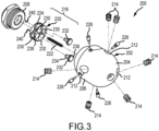
- Nozzle assembly 200 is similar to nozzle assembly 100 described above except that the flow diverter 118 has been eliminated. This functionality is incorporated into the front portion of the nozzle body.
- Nozzle assembly 200 has a generally cylindrical solid nozzle body 202 with a front portion 204 which typically has a rounded nose and a generally cylindrical rear portion 206 that can be threadably fastened to an inlet nut 208 , which is, in turn, fastened to a rotary shaft and thence to a high pressure fluid hose (not shown).
- This nozzle body 202 has a central bore 210 through at least the rear portion 206 of the nozzle body 202 and a plurality of ports 212 drilled through the body 202 each leading from the central bore 210 to a nozzle tip 214 that is threaded into each of the ports 212 .
- This switching valve assembly 216 includes a cylindrical poppet 220 slidably disposed in the central bore 210 , a bias member 222 compressed between the poppet 220 and the front portion 204 , and a guide 224 between the poppet 220 and the nozzle body 202 .
- the guide 224 comprises a groove in the poppet 220 that engages a plurality of guide pins 226 that are threaded into the body 202 and extend into the central bore 210.
- the groove 224 is a peripheral zig-zag groove formed in the outer cylindrical surface of the poppet 220 .
- the poppet 220 slides within the bore 210 forward toward the front portion 204 of the nozzle body 202 , being rotated as it moves via the guide 224 until its front end face 238 abuts against the rear face of the front portion 204 at the end of the central bore 210 .
- the poppet 220 is a short cylindrical body that has four axially extending bores 230 symmetrically arranged around its central axis. Two oppositely arranged bores 230 carry floating valve pins 232 . These valve pins 232 are used to close corresponding aligned passages 228 through the front portion 204 of the nozzle body 202 . Each valve pin 232 has a stem 234 and an enlarged plug portion 236 extend from a front face 238 of the poppet 220 giving the valve pin an external shape like an Erlenmeyer flask.
- valve pins 232 are each captured within its bore 230 via a snap ring 240 fastened to the stem 234 of the valve pin 232 such that the valve pin 232 floats within its bore through the poppet 220 .
- This floating configuration with an enlarged plug or lug end portion 236 accommodates for tolerance stacking of the nozzle switching valve 216 components.
- an O-ring seal (not shown) may be installed between the chamfer of the enlarged plug portion 236 and the front portion 204 of the nozzle body 202 to provide a positive seal.
- the other two bores 230 (shown in FIG. 5 ) through the poppet 220 provide a flow path to the passages 228 in the front portion 204 of the nozzle body 202 .
- the passages 228 directed to the cleaning ports 212 are plugged.
- the passages 228 that are shown in the sectional view of FIG. 5 are not plugged permitting fluid flow directly to the tractor and forward ports 212 through the front portion 204 of the nozzle body 202 .
- FIG. 4 shows the poppet 220 closing two axial passages 228 into the front portion 204 of the nozzle body 202 .
- a cross sectional view 90° rotated from that shown is shown in FIG. 5 showing the opposite straight through bores 230 through the poppet 220 aligned with axial passages 228 in the front portion 204 .
- the view of FIGS 4 and 5 shows the nozzle 200 with the switching valve assembly 216 aligned to provide fluid flow to the lateral cleaning ports 212 .
- the poppet 220 When fluid flow next drops below a threshold flow defined by the spring rate of spring 222 , the poppet 220 would move rearward along the zig zag path of the peripheral groove of the guide 224 .
- poppet 220 When flow next exceeds the threshold, poppet 220 would move forward and rotate to align the straight through passages with the other pair of passages 228 to the tractor and forward ports 212 .
- This nozzle assembly 300 includes a hollow nozzle body 302 that has a round nose front portion 304 and a generally cylindrical rear portion 306 .
- the nozzle body 302 has a central blind bore 310 that receives a removable valve cartridge 312.
- the blind bore 310 has a block shaped front portion 314 and a circular cylindrical rear portion 316 .
- This removable cartridge 312 is shaped complementary to the central blind bore 310 and is captured within the blind bore 310 by a nozzle inlet nut 308 fastened to the nozzle body 302 and which, in turn, connects to a rotatable shaft and thence to a high pressure fluid hose (not shown).
- the removable cartridge 312 includes a case 318 externally shaped complementary to the blind bore 310 with a front block portion 320 that acts as a flow diverter having a plurality of passages therethrough each configured to align with a port drilled through the nozzle body 302 into the front portion 314 of the blind bore 310 .
- the case 318 has a hollow circular cylindrical rear portion 322 that carries within it a switching valve assembly 324.
- This switching valve assembly 324 is similar to the switching valve assemblies 116 and 216 described above.
- This switching valve assembly 324 includes a cylindrical poppet 326 slidably disposed in the cylindrical rear portion 322 of the case 318 , a bias member 328 compressed between the poppet 326 and the front portion 320 of the case 318 , and a guide 330 operating between the poppet 326 and the rear portion 322 of the case 318 .
- the guide 330 comprises a groove 332 in the poppet 326 that engages a plurality of guide pins 334 that are threaded into the case 318 and extend into the rear portion 322 of the case 318 .
- the groove 332 is a peripheral zig-zag groove formed in the outer cylindrical surface of the poppet 326 .
- the poppet 326 is a short cylindrical body that has four axially extending bores 338, shown in FIG. 6 , symmetrically arranged 90° apart around its central axis.
- Two oppositely arranged bores 338 carry floating valve pins 340 .
- These valve pins 340 are used to close corresponding aligned passages 342 through the front portion 320 of the cartridge case 318 .
- Each valve pin 340 has a stem 344 and an enlarged plug portion 346 that extends from a front face 336 of the poppet 326 giving the valve pin 340 an external shape like an Erlenmeyer flask.
- valve pins 340 are each captured within its bore 338 via a snap ring 348 fastened to the stem 344 of the valve pin 340 such that the valve pin 340 floats within its bore 338 through the poppet 326 .
- This floating configuration with an enlarged plug or lug end portion 346 accommodates for tolerance stacking of the nozzle switching valve 326 components.
- an O-ring seal (not shown) may be installed between the chamfer of the enlarged plug portion 346 and each passage 342 in the front portion 320 of the cartridge case 318 to provide a positive seal.
- the other two bores 338 (shown in FIG. 7 ) through the poppet 326 provide a flow path to the passages 342 in the front portion 320 of the cartridge case 318.
- the passages 338 directed to the cleaning ports 350 are plugged.
- the passages 338 that are shown in the sectional view of FIG. 7 are not plugged permitting fluid flow directly to the tractor and forward ports 350 through the front portion 320 of the case 318 and thence through the front portion 304 of the nozzle body 302 .
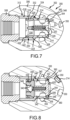
- FIG. 8 shows the poppet 326 closing two axial passages 342 into the front portion 320 of the cartridge case 318 .
- FIG. 8 is a cross sectional view 90° rotated from that shown is shown in FIG. 7 showing the opposite straight through bores 338 through the poppet 326 aligned with axial passages 342 in the front portion 320 .
- the views in both FIGS 7 and 8 show the nozzle 300 with the switching valve assembly 324 aligned to provide fluid flow to the tractor and forward ports 350 .
- the poppet 326 When fluid flow next drops below a threshold defined by the spring rate of spring bias member 328, the poppet 326 would move rearward along the zig zag path of the peripheral groove of the guide 330 .
- poppet 326 When flow next exceeds the threshold pressure, poppet 326 would move forward and rotates to align the straight through passages with the other pair of passages 342 to the lateral cleaning ports 350 .
- Each port 350 receives a threaded nozzle tip 214 as in the embodiments previously described.
- the front block portion 320 of the case 318 in this embodiment 300 has four axially straight side faces 352 and a flat end face 354. Each of these faces 352 has a circular groove 356 carrying an O-ring 357 and a plastic face seal 358 around an opening to its corresponding port 350 in the front portion 304 of the nozzle head body 302 .
- the circular groove 356 may optionally also carry an annular metal anti-extrusion ring 360 to prevent extrusion of the plastic face seal 358 when the nozzle 300 is under pressure.
- the plastic face seal 358 bridges the gap between the case 318 and the nozzle body 302 .
- the extrusion ring 360 also keeps the plastic face seal 358 in proper position during insertion and removal of the case 318 in the central bore 310 of the nozzle body 302 .
- This cartridge case 318 may be made of a metal or thermoplastic material such as a high molecular weight polyethylene and may be injection molded. One preferable material is ultra-high molecular weight polyethylene.
- the poppet 326 itself may be made of a plastic rather than metal.
- the valve assembly 324 may be made of plastic as it does not have to withstand the high stresses encountered during nozzle operation.
- the nozzle head body 302 and inlet nut 308 provide the strength required for high pressure operation.
- FIGS. 9 through 11 Another alternative embodiment of a nozzle head incorporating a switching valve in accordance with the present disclosure is shown in FIGS. 9 through 11 .
- This nozzle assembly 400 includes a hollow nozzle body 402 that has a round nose front portion 404 and a generally cylindrical rear portion 406 .
- the nozzle body 402 has a central blind bore 410 that receives a removable valve cartridge 412 .
- the blind bore 410 has a truncated conical tapered front portion 414 and a circular cylindrical rear portion 416 .
- This removable cartridge 412 is captured within the blind bore 410 by a nozzle inlet nut 408 fastened to the nozzle body 402 and which, in turn, connects to a high pressure hose or to a rotary shaft (not shown).
- the removable cartridge 412 includes a case 418 externally shaped complementary to the blind bore 410 with a front tapered portion 420 that acts as a flow diverter having a plurality of passages therethrough each configured to align with a port 450 drilled through the nozzle body 402 into the front portion 414 of the blind bore 410 .
- the case 418 has a hollow circular cylindrical rear portion 422 that carries within it a portion of a switching valve assembly 424 .
- This switching valve assembly 424 functions similar to the switching valve assemblies 116, 216 and 324 described above.
- This switching valve assembly 424 includes a cylindrical poppet 426 slidably disposed partially in the cylindrical rear portion 422 of the case 418 and partially in the front portion 420 of the case 418 , a bias member 428 compressed between the poppet 426 and the front portion 420 of the case 418 , to the front portion 404 of the nozzle body 402 and a guide 430 operating between the poppet 426 and the rear portion 422 of the case 418 .
- the guide in this embodiment 400 comprises a stationary tubular sleeve 430 set into the rear portion 422 of the case 418 that has an internal zig-zag groove 432 .
- the poppet 426 includes a plurality of radially protruding pins 434 each engaging the groove 432 in the sleeve 430 set into the rear portion 422 of the case 418 .
- the pins 434 are threaded through a rear portion of the poppet 426 and extend radially outward so as to ride in the groove 432 as the poppet 426 moves back and forth in the case 418 .
- the poppet 426 slides within the case 418 forward toward the front portion 420 of the case 418 , being rotated as it moves via the guide 430 until its front end face 436 abuts against the front portion 420 of the case 418 .
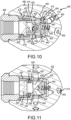
- the poppet 426 is a short cylindrical body that has a common rear opening that diverges to four bores 438 symmetrically arranged 90° apart around its central axis. Two are biased forward, and two are biased rearward. Two oppositely arranged bores 438 are radially directed and carry floating valve plugs 440 . In this embodiment, the floating valve plugs 440 free float in their radial bores 438 . These valve plugs 440 close corresponding aligned passages 442 through the side of the front portion 420 of the cartridge case 418 as shown in FIG. 10 .
- the other two bores 438 (shown in FIG. 11 ) through the poppet 426 provide a flow path to the passages 442 through the side of the front portion 420 of the cartridge case 418.
- the passages 438 directed to the tractor and front or forward ports 450 are plugged.
- the passages 438 that are shown in the sectional view of FIG. 11 are not plugged permitting fluid flow directly to the cleaning ports 450 through the front portion 420 of the case 418 .
- FIGS. 10 and 11 both show the same configuration, with the cleaning ports open and the forward and tractor ports plugged.
- FIG. 10 shows the poppet 426 closing two axial passages 442 into the front portion 420 of the cartridge case 418 .
- a cross sectional view 90° rotated from that shown is shown in FIG. 11 showing the opposite through bores 438 through the poppet 426 aligned with axial passages 442 in the front portion 420 .
- the view of FIGS 10 and 11 shows the nozzle 400 with the switching valve assembly 424 aligned to provide fluid flow to the cleaning ports 450 .
- poppet 426 When fluid pressure next drops below a threshold flow defined by the spring rate of spring bias member 428 , the poppet 426 would move rearward along the zig zag path of the peripheral groove of the guide 430 . When flow next exceeds the threshold pressure, poppet 426 would move forward and rotates to align the poppet passages with the other pair of passages 442 to the tractor and forward ports 450 .
- the front tapered portion 420 of the case 418 in this embodiment 400 has a single circular conical side face 452 and an open end face 454 . Because of the tapered conical side face 452 , there is no need for an O ring seal around each of the four port openings 450 as in embodiment 300 , as the taper itself provides the seal.
- the end of the poppet 426 provides a seat that seals the end face 454 of the case 418 when the poppet is aligned with the cleaning ports as shown in FIGS. 9-11 . When the poppet is aligned to provide flow to the tractor ports, the poppet 426 is displaced from the end face 454 of the case 418 to permit flow through passages 438 to the forward ports 450 .
- This cartridge case 418 may be made of a metal or thermoplastic material and may be injection molded.
- One preferable material is ultra-high density polyethylene.
- the poppet 426 itself may be made of a plastic rather than metal.
- the components of the valve assembly 424 may be made of plastic.
- the valve pins do see full pressure and therefore may be made of metal or a different high strength plastic.
- the nozzle head body 402 and inlet nut 408 primarily provide the strength required for containment of the cartridge 412 during high pressure operation.
- Each of the ports 450 preferably carries a removable threaded nozzle tip 214 just as in the previously described embodiments.
- the guide pins 434 may be threaded through the wall of the poppet 426 or may be press fit.
- the poppet 426 may have a peripheral groove as in the first three embodiments described above and the cartridge case 418 provided with the guide pins.
Landscapes
- Engineering & Computer Science (AREA)
- Chemical & Material Sciences (AREA)
- Combustion & Propulsion (AREA)
- General Engineering & Computer Science (AREA)
- Mechanical Engineering (AREA)
- Physics & Mathematics (AREA)
- Fluid Mechanics (AREA)
- Nozzles (AREA)
- Multiple-Way Valves (AREA)
Claims (14)
- Buse comprenant :un écrou d'entrée (108, 208, 308, 408) qui peut être fixé à une extrémité distale d'un élément parmi un arbre de buse rotatif ou un flexible haute pression ;un corps de buse creux (102, 202, 302, 402) présentant une partie avant (104, 204, 304, 404), une partie d'entrée arrière (106, 206, 306, 406) configurée pour venir en prise avec l'écrou d'entrée (108, 208, 308, 408), un alésage central (110, 210, 310, 410) à travers au moins la partie d'entrée arrière (106, 206, 306, 406) du corps de buse (102, 202, 302, 402), et une pluralité d'orifices (112, 350, 450) s'étendant à travers le corps de buse (102, 202, 302, 402) à partir de l'alésage central (110, 210, 310, 410) ; etun ensemble de soupapes de commutation (116, 216, 324, 424) disposé dans l'alésage central (110, 210, 310, 410) qui peut fonctionner pour diriger un écoulement de fluide à partir de la partie d'entrée (106, 206, 306, 406) jusqu'à au moins un ensemble parmi la pluralité d'orifices (112, 350, 450) lors de l'application d'un écoulement de fluide au-dessus d'un seuil prédéterminé sur la partie d'entrée (106, 206, 306, 406) et diriger un écoulement de fluide à partir de la partie d'entrée (106, 206, 306, 406) jusqu'à au moins un ensemble différent parmi la pluralité d'orifices (112, 350, 450) lors de l'écoulement de fluide qui est ensuite descendu au-dessous du seuil d'écoulement prédéterminé et puis a dépassé le seuil prédéterminé, l'ensemble de soupapes de commutation (116, 216, 324, 424) comprenant :un clapet cylindrique (120, 220, 326, 426) disposé de manière coulissante dans l'alésage central (110, 210, 310, 410), le clapet (120, 220, 326, 426) présentant au moins un alésage traversant qui s'étend axialement (130, 230) pour permettre un écoulement de fluide à travers celui-ci et un autre alésage (130, 230) contenant une goupille de soupape (132, 232, 340) capturée à l'intérieur de l'autre alésage et qui fait saillie à partir de celui-ci pour fermer au moins un des orifices (112) ;un guide (126, 226, 334, 434) coopérant avec le clapet pour faire tourner le clapet (120, 220, 326, 426) dans une direction afin d'alterner un écoulement de fluide entre les orifices (112, 350, 450) ; etun élément de sollicitation (122, 222, 322, 422) entre la partie avant (104, 204, 304, 404) du corps de buse (102, 202, 302, 402) et le clapet (120, 220, 326, 426) qui pousse le clapet (120, 220, 326, 426) à distance de la partie avant (104, 204, 304, 404) du corps de buse (102, 202, 302, 402).
- Ensemble de buse selon la revendication 1, dans lequel le guide (126, 226, 334, 434) inclut un ou plusieurs éléments de guide (126, 226, 334, 434) qui viennent en prise avec le clapet (120, 220, 326, 426) afin d'aligner alternativement en rotation le clapet (120, 220, 326, 426) avec l'au moins un ensemble de la pluralité d'orifices (112) et l'ensemble différent de la pluralité d'orifices (112) à chaque fois que le clapet (120, 220, 326, 426) vient en butée contre la partie avant (104, 204, 304, 404) du corps de buse (102, 202, 302, 402).
- Ensemble de buse selon la revendication 1, dans lequel l'élément de guide (126, 226, 334, 434) comprend des goupilles de guide (126, 226, 334, 434) qui font saillie vers l'intérieur depuis la partie d'entrée arrière (106, 206, 306, 406) du corps de buse (102, 202, 302, 402) jusque dans l'alésage central (110, 210, 310, 410) venant en prise avec le clapet (120, 220, 326, 426).
- Ensemble de buse selon la revendication 2, dans lequel le clapet (120, 220, 326, 426) présente une rainure périphérique (124) qui vient en prise avec l'un ou plusieurs éléments de guide (126, 226, 334, 434).
- Ensemble de buse selon la revendication 4, dans lequel chaque transition au-dessous du seuil prédéterminé amène le clapet (120, 220, 326, 426) à tourner jusqu'à une position angulaire différente afin de permettre à un écoulement de fluide d'alterner entre l'ensemble d'orifices (112) et l'ensemble différent d'orifices (112).
- Ensemble de buse selon la revendication 1, dans lequel l'ensemble de soupapes de commutation (116, 216, 324, 424) inclut un boîtier tubulaire détachable (318) à l'intérieur de l'alésage central (110, 210, 310, 410) portant le clapet (120, 220, 326, 426) et le guide (126, 226, 334, 434) à l'intérieur, dans lequel le boîtier tubulaire (318) présente une partie avant (320) et une partie arrière (322), la partie arrière (322) portant le clapet (326) et le guide (330) à l'intérieur, et l'élément de sollicitation (328) est à l'intérieur de la partie avant (320) du boîtier tubulaire (318).
- Ensemble de buse selon la revendication 6, dans lequel la partie avant (320) du boîtier tubulaire (318) présente au moins un alésage à travers celui-ci menant au premier ensemble d'orifices (350) et au moins un autre alésage à travers celui-ci menant au second ensemble d'orifices (350).
- Ensemble de buse selon la revendication 7, dans lequel le clapet (326) présente une face avant et la goupille de soupape (340) capturée dans l'au moins un autre alésage traversant (338) présente une partie d'ergot qui fait saillie depuis la face avant afin de fermer de manière sélective l'au moins un alésage à travers la partie avant (320) du boîtier tubulaire (318).
- Ensemble de buse selon la revendication 7, dans lequel le clapet (326) est un corps cylindrique circulaire présentant une pluralité d'alésages traversants (338) et au moins un des alésages traversants capture une goupille de soupape (340) à l'intérieur présentant une partie d'extrémité en forme d'ergot qui fait saillie à partir d'une face avant du clapet (326) pour fermer de manière sélective l'au moins un alésage (338) à travers la partie avant (320) du boîtier tubulaire (318).
- Ensemble de buse selon la revendication 1, dans lequel le guide (330) fait tourner le clapet (326) d'une quantité prédéterminée à chaque fois que le clapet (326) se déplace vers ou à distance de la partie avant (304) du corps de buse (302).
- Ensemble de buse selon la revendication 6, dans lequel le boîtier (318) présente deux ou plusieurs alésages axiaux à travers la partie avant (320) espacés de manière égale autour d'un axe central à travers le boîtier et deux ou plusieurs alésages d'angle à travers la partie avant (320) s'étendant à travers un côté du boîtier (318).
- Ensemble de buse selon la revendication 1, dans lequel l'ensemble de soupapes de commutation (424) inclut un boîtier tubulaire détachable (418) à l'intérieur de l'alésage portant le clapet (426) et le guide (430) à l'intérieur, dans lequel le boîtier (418) présente une partie conique avant (420) et une partie arrière (422), la partie arrière (422) portant le clapet (426) et le guide (430) à l'intérieur, et l'élément de sollicitation (428) est à l'intérieur de la partie avant (420) du boîtier tubulaire (418).
- Ensemble de buse selon la revendication 12, dans lequel l'ensemble de soupapes de commutation (424) inclut en outre un manchon de guide tubulaire disposé à l'intérieur de la partie arrière (422) du boîtier (418) et le clapet (426) inclut des bouchons mobiles (440) disposés dans des alésages radiaux (438) pour fermer des orifices dans le corps de buse (450).
- Ensemble de buse selon la revendication 13, dans lequel le clapet (426) présente des goupilles de guide (434) qui font saillie radialement vers l'extérieur venant en prise avec des rainures formées dans le manchon de guide afin de faire tourner le clapet (426).
Applications Claiming Priority (2)
| Application Number | Priority Date | Filing Date | Title |
|---|---|---|---|
| US201862745119P | 2018-10-12 | 2018-10-12 | |
| PCT/US2019/054112 WO2020076563A1 (fr) | 2018-10-12 | 2019-10-01 | Buse de pulvérisation de fluide haute pression renfermant une soupape de commutation à écoulement régulé |
Publications (3)
| Publication Number | Publication Date |
|---|---|
| EP3843904A1 EP3843904A1 (fr) | 2021-07-07 |
| EP3843904A4 EP3843904A4 (fr) | 2021-10-20 |
| EP3843904B1 true EP3843904B1 (fr) | 2024-11-13 |
Family
ID=70162359
Family Applications (1)
| Application Number | Title | Priority Date | Filing Date |
|---|---|---|---|
| EP19871168.1A Active EP3843904B1 (fr) | 2018-10-12 | 2019-10-01 | Buse de pulvérisation de fluide haute pression renfermant une soupape de commutation à écoulement régulé |
Country Status (5)
| Country | Link |
|---|---|
| US (1) | US11198141B2 (fr) |
| EP (1) | EP3843904B1 (fr) |
| AU (2) | AU2019357892B2 (fr) |
| CA (1) | CA3114410A1 (fr) |
| WO (1) | WO2020076563A1 (fr) |
Families Citing this family (8)
| Publication number | Priority date | Publication date | Assignee | Title |
|---|---|---|---|---|
| CN111822457B (zh) * | 2020-06-28 | 2024-09-24 | 叶中樵 | 一种用于管道内的清洁涂油装置 |
| USD1002799S1 (en) * | 2021-09-30 | 2023-10-24 | Paul DEL PIERO | Nozzle for pressure washer |
| USD1037410S1 (en) * | 2023-01-26 | 2024-07-30 | Stoneage, Inc. | Descaler cleaner with smooth body and forward nozzle head |
| USD1065437S1 (en) * | 2023-01-26 | 2025-03-04 | Stoneage, Inc. | Descaler cleaner with narrow nozzle head |
| USD1065438S1 (en) * | 2023-01-26 | 2025-03-04 | Stoneage, Inc. | Descaler cleaner with short nozzle head and ramped body fins |
| USD1065436S1 (en) * | 2023-01-26 | 2025-03-04 | Stoneage, Inc | Universal cleaner with nozzle head and ramped body fins |
| USD1065439S1 (en) * | 2023-01-26 | 2025-03-04 | Stoneage, Inc. | Descaler cleaner with large nozzle head |
| USD1066570S1 (en) * | 2023-01-26 | 2025-03-11 | Stoneage, Inc. | Universal cleaner with short nozzle head |
Family Cites Families (9)
| Publication number | Priority date | Publication date | Assignee | Title |
|---|---|---|---|---|
| SE9300645L (sv) * | 1993-02-26 | 1994-08-27 | Johan Faxon | Förfarande och anordning för rengöring av rörledningar |
| US6059202A (en) | 1998-04-30 | 2000-05-09 | Stoneage, Inc. | High pressure liquid rotary coupling with slip seal |
| US7513261B2 (en) * | 1999-12-16 | 2009-04-07 | Kimasaru Ura | Method and device for washing drain pipe |
| US8667987B2 (en) | 2011-02-14 | 2014-03-11 | Stoneage, Inc. | Flow controlled switching valve |
| US9395001B2 (en) * | 2014-03-18 | 2016-07-19 | Stoneage, Inc. | High pressure fluid spray nozzle incorporating a flow controlled switching valve |
| CH707524B1 (de) * | 2013-01-24 | 2016-09-15 | Enz Technik Ag | Druckmediumbetriebene Rohrreinigungsdüse. |
| EP2775051B1 (fr) * | 2013-03-05 | 2019-01-16 | Unilever N.V. | Dispositif pulvérisateur avec une chambre de dosage |
| WO2016115123A1 (fr) | 2015-01-12 | 2016-07-21 | Pentair Flow Technologies, Llc | Système et procédé de buse à écoulement variable |
| US10730060B2 (en) * | 2018-09-11 | 2020-08-04 | Xiamen EASO Co., Ltd. | Convenient switching valve |
-
2019
- 2019-10-01 AU AU2019357892A patent/AU2019357892B2/en active Active
- 2019-10-01 CA CA3114410A patent/CA3114410A1/fr active Pending
- 2019-10-01 WO PCT/US2019/054112 patent/WO2020076563A1/fr not_active Ceased
- 2019-10-01 EP EP19871168.1A patent/EP3843904B1/fr active Active
- 2019-10-01 US US16/590,175 patent/US11198141B2/en active Active
-
2025
- 2025-09-26 AU AU2025238058A patent/AU2025238058A1/en active Pending
Also Published As
| Publication number | Publication date |
|---|---|
| US20200114371A1 (en) | 2020-04-16 |
| AU2019357892B2 (en) | 2025-06-26 |
| US11198141B2 (en) | 2021-12-14 |
| CA3114410A1 (fr) | 2020-04-16 |
| EP3843904A4 (fr) | 2021-10-20 |
| WO2020076563A1 (fr) | 2020-04-16 |
| AU2019357892A1 (en) | 2021-04-29 |
| AU2025238058A1 (en) | 2025-10-30 |
| EP3843904A1 (fr) | 2021-07-07 |
Similar Documents
| Publication | Publication Date | Title |
|---|---|---|
| US11198141B2 (en) | High pressure fluid spray nozzle incorporating a flow controlled switching valve | |
| US8863775B2 (en) | High pressure fluid spray nozzle incorporating a flow controlled switching valve | |
| US12194480B2 (en) | Switcher nozzle high efficiency flow insert | |
| US9617812B2 (en) | Drillstring valve | |
| PL199474B1 (pl) | Zawór sterujący, zwłaszcza do hydraulicznych urządzeń górniczych | |
| EP1031368B1 (fr) | Indicateur pour la condition d' un filtre | |
| NZ631309B2 (en) | High pressure fluid spray nozzle incorporating a flow controlled switching valve | |
| NZ613814B2 (en) | High pressure fluid spray nozzle incorporating a flow controlled switching valve |
Legal Events
| Date | Code | Title | Description |
|---|---|---|---|
| STAA | Information on the status of an ep patent application or granted ep patent |
Free format text: STATUS: THE INTERNATIONAL PUBLICATION HAS BEEN MADE |
|
| STAA | Information on the status of an ep patent application or granted ep patent |
Free format text: STATUS: REQUEST FOR EXAMINATION WAS MADE |
|
| PUAI | Public reference made under article 153(3) epc to a published international application that has entered the european phase |
Free format text: ORIGINAL CODE: 0009012 |
|
| 17P | Request for examination filed |
Effective date: 20210401 |
|
| AK | Designated contracting states |
Kind code of ref document: A1 Designated state(s): AL AT BE BG CH CY CZ DE DK EE ES FI FR GB GR HR HU IE IS IT LI LT LU LV MC MK MT NL NO PL PT RO RS SE SI SK SM TR |
|
| REG | Reference to a national code |
Ref country code: DE Ipc: B05B0001300000 Ref country code: DE Ref legal event code: R079 Ref document number: 602019062066 Country of ref document: DE Free format text: PREVIOUS MAIN CLASS: B05B0001160000 Ipc: B05B0001300000 |
|
| A4 | Supplementary search report drawn up and despatched |
Effective date: 20210916 |
|
| RIC1 | Information provided on ipc code assigned before grant |
Ipc: F16L 55/38 20060101ALI20210910BHEP Ipc: F16L 101/50 20060101ALI20210910BHEP Ipc: F16L 101/12 20060101ALI20210910BHEP Ipc: B08B 9/049 20060101ALI20210910BHEP Ipc: B05B 12/04 20060101ALI20210910BHEP Ipc: B05B 1/16 20060101ALI20210910BHEP Ipc: B05B 1/30 20060101AFI20210910BHEP |
|
| DAV | Request for validation of the european patent (deleted) | ||
| DAX | Request for extension of the european patent (deleted) | ||
| P01 | Opt-out of the competence of the unified patent court (upc) registered |
Effective date: 20240301 |
|
| GRAP | Despatch of communication of intention to grant a patent |
Free format text: ORIGINAL CODE: EPIDOSNIGR1 |
|
| STAA | Information on the status of an ep patent application or granted ep patent |
Free format text: STATUS: GRANT OF PATENT IS INTENDED |
|
| INTG | Intention to grant announced |
Effective date: 20240710 |
|
| GRAS | Grant fee paid |
Free format text: ORIGINAL CODE: EPIDOSNIGR3 |
|
| GRAA | (expected) grant |
Free format text: ORIGINAL CODE: 0009210 |
|
| STAA | Information on the status of an ep patent application or granted ep patent |
Free format text: STATUS: THE PATENT HAS BEEN GRANTED |
|
| AK | Designated contracting states |
Kind code of ref document: B1 Designated state(s): AL AT BE BG CH CY CZ DE DK EE ES FI FR GB GR HR HU IE IS IT LI LT LU LV MC MK MT NL NO PL PT RO RS SE SI SK SM TR |
|
| REG | Reference to a national code |
Ref country code: GB Ref legal event code: FG4D |
|
| REG | Reference to a national code |
Ref country code: CH Ref legal event code: EP |
|
| REG | Reference to a national code |
Ref country code: IE Ref legal event code: FG4D |
|
| REG | Reference to a national code |
Ref country code: DE Ref legal event code: R096 Ref document number: 602019062066 Country of ref document: DE |
|
| REG | Reference to a national code |
Ref country code: NL Ref legal event code: FP |
|
| REG | Reference to a national code |
Ref country code: LT Ref legal event code: MG9D |
|
| PG25 | Lapsed in a contracting state [announced via postgrant information from national office to epo] |
Ref country code: HR Free format text: LAPSE BECAUSE OF FAILURE TO SUBMIT A TRANSLATION OF THE DESCRIPTION OR TO PAY THE FEE WITHIN THE PRESCRIBED TIME-LIMIT Effective date: 20241113 Ref country code: PT Free format text: LAPSE BECAUSE OF FAILURE TO SUBMIT A TRANSLATION OF THE DESCRIPTION OR TO PAY THE FEE WITHIN THE PRESCRIBED TIME-LIMIT Effective date: 20250313 Ref country code: IS Free format text: LAPSE BECAUSE OF FAILURE TO SUBMIT A TRANSLATION OF THE DESCRIPTION OR TO PAY THE FEE WITHIN THE PRESCRIBED TIME-LIMIT Effective date: 20250313 |
|
| PG25 | Lapsed in a contracting state [announced via postgrant information from national office to epo] |
Ref country code: FI Free format text: LAPSE BECAUSE OF FAILURE TO SUBMIT A TRANSLATION OF THE DESCRIPTION OR TO PAY THE FEE WITHIN THE PRESCRIBED TIME-LIMIT Effective date: 20241113 |
|
| REG | Reference to a national code |
Ref country code: AT Ref legal event code: MK05 Ref document number: 1741283 Country of ref document: AT Kind code of ref document: T Effective date: 20241113 |
|
| PG25 | Lapsed in a contracting state [announced via postgrant information from national office to epo] |
Ref country code: BG Free format text: LAPSE BECAUSE OF FAILURE TO SUBMIT A TRANSLATION OF THE DESCRIPTION OR TO PAY THE FEE WITHIN THE PRESCRIBED TIME-LIMIT Effective date: 20241113 |
|
| PG25 | Lapsed in a contracting state [announced via postgrant information from national office to epo] |
Ref country code: ES Free format text: LAPSE BECAUSE OF FAILURE TO SUBMIT A TRANSLATION OF THE DESCRIPTION OR TO PAY THE FEE WITHIN THE PRESCRIBED TIME-LIMIT Effective date: 20241113 |
|
| PG25 | Lapsed in a contracting state [announced via postgrant information from national office to epo] |
Ref country code: NO Free format text: LAPSE BECAUSE OF FAILURE TO SUBMIT A TRANSLATION OF THE DESCRIPTION OR TO PAY THE FEE WITHIN THE PRESCRIBED TIME-LIMIT Effective date: 20250213 |
|
| PG25 | Lapsed in a contracting state [announced via postgrant information from national office to epo] |
Ref country code: AT Free format text: LAPSE BECAUSE OF FAILURE TO SUBMIT A TRANSLATION OF THE DESCRIPTION OR TO PAY THE FEE WITHIN THE PRESCRIBED TIME-LIMIT Effective date: 20241113 Ref country code: LV Free format text: LAPSE BECAUSE OF FAILURE TO SUBMIT A TRANSLATION OF THE DESCRIPTION OR TO PAY THE FEE WITHIN THE PRESCRIBED TIME-LIMIT Effective date: 20241113 Ref country code: GR Free format text: LAPSE BECAUSE OF FAILURE TO SUBMIT A TRANSLATION OF THE DESCRIPTION OR TO PAY THE FEE WITHIN THE PRESCRIBED TIME-LIMIT Effective date: 20250214 |
|
| PG25 | Lapsed in a contracting state [announced via postgrant information from national office to epo] |
Ref country code: PL Free format text: LAPSE BECAUSE OF FAILURE TO SUBMIT A TRANSLATION OF THE DESCRIPTION OR TO PAY THE FEE WITHIN THE PRESCRIBED TIME-LIMIT Effective date: 20241113 |
|
| PG25 | Lapsed in a contracting state [announced via postgrant information from national office to epo] |
Ref country code: RS Free format text: LAPSE BECAUSE OF FAILURE TO SUBMIT A TRANSLATION OF THE DESCRIPTION OR TO PAY THE FEE WITHIN THE PRESCRIBED TIME-LIMIT Effective date: 20250213 |
|
| PG25 | Lapsed in a contracting state [announced via postgrant information from national office to epo] |
Ref country code: SM Free format text: LAPSE BECAUSE OF FAILURE TO SUBMIT A TRANSLATION OF THE DESCRIPTION OR TO PAY THE FEE WITHIN THE PRESCRIBED TIME-LIMIT Effective date: 20241113 |
|
| PG25 | Lapsed in a contracting state [announced via postgrant information from national office to epo] |
Ref country code: DK Free format text: LAPSE BECAUSE OF FAILURE TO SUBMIT A TRANSLATION OF THE DESCRIPTION OR TO PAY THE FEE WITHIN THE PRESCRIBED TIME-LIMIT Effective date: 20241113 |
|
| PG25 | Lapsed in a contracting state [announced via postgrant information from national office to epo] |
Ref country code: EE Free format text: LAPSE BECAUSE OF FAILURE TO SUBMIT A TRANSLATION OF THE DESCRIPTION OR TO PAY THE FEE WITHIN THE PRESCRIBED TIME-LIMIT Effective date: 20241113 |
|
| PG25 | Lapsed in a contracting state [announced via postgrant information from national office to epo] |
Ref country code: RO Free format text: LAPSE BECAUSE OF FAILURE TO SUBMIT A TRANSLATION OF THE DESCRIPTION OR TO PAY THE FEE WITHIN THE PRESCRIBED TIME-LIMIT Effective date: 20241113 |
|
| PG25 | Lapsed in a contracting state [announced via postgrant information from national office to epo] |
Ref country code: SK Free format text: LAPSE BECAUSE OF FAILURE TO SUBMIT A TRANSLATION OF THE DESCRIPTION OR TO PAY THE FEE WITHIN THE PRESCRIBED TIME-LIMIT Effective date: 20241113 |
|
| PG25 | Lapsed in a contracting state [announced via postgrant information from national office to epo] |
Ref country code: CZ Free format text: LAPSE BECAUSE OF FAILURE TO SUBMIT A TRANSLATION OF THE DESCRIPTION OR TO PAY THE FEE WITHIN THE PRESCRIBED TIME-LIMIT Effective date: 20241113 |
|
| REG | Reference to a national code |
Ref country code: DE Ref legal event code: R097 Ref document number: 602019062066 Country of ref document: DE |
|
| PG25 | Lapsed in a contracting state [announced via postgrant information from national office to epo] |
Ref country code: SE Free format text: LAPSE BECAUSE OF FAILURE TO SUBMIT A TRANSLATION OF THE DESCRIPTION OR TO PAY THE FEE WITHIN THE PRESCRIBED TIME-LIMIT Effective date: 20241113 |
|
| PLBE | No opposition filed within time limit |
Free format text: ORIGINAL CODE: 0009261 |
|
| STAA | Information on the status of an ep patent application or granted ep patent |
Free format text: STATUS: NO OPPOSITION FILED WITHIN TIME LIMIT |
|
| PGFP | Annual fee paid to national office [announced via postgrant information from national office to epo] |
Ref country code: IT Payment date: 20250922 Year of fee payment: 7 Ref country code: NL Payment date: 20250912 Year of fee payment: 7 |
|
| PGFP | Annual fee paid to national office [announced via postgrant information from national office to epo] |
Ref country code: BE Payment date: 20250917 Year of fee payment: 7 Ref country code: GB Payment date: 20250904 Year of fee payment: 7 |
|
| PGFP | Annual fee paid to national office [announced via postgrant information from national office to epo] |
Ref country code: FR Payment date: 20250908 Year of fee payment: 7 |
|
| 26N | No opposition filed |
Effective date: 20250814 |
|
| PGFP | Annual fee paid to national office [announced via postgrant information from national office to epo] |
Ref country code: DE Payment date: 20250902 Year of fee payment: 7 |
|
| REG | Reference to a national code |
Ref country code: CH Ref legal event code: U11 Free format text: ST27 STATUS EVENT CODE: U-0-0-U10-U11 (AS PROVIDED BY THE NATIONAL OFFICE) Effective date: 20260218 |
|
| PGFP | Annual fee paid to national office [announced via postgrant information from national office to epo] |
Ref country code: CH Payment date: 20260218 Year of fee payment: 7 |