EP3844021B1 - Siège de véhicule et procédé servant à faire fonctionner un siège de véhicule - Google Patents
Siège de véhicule et procédé servant à faire fonctionner un siège de véhicule Download PDFInfo
- Publication number
- EP3844021B1 EP3844021B1 EP19759363.5A EP19759363A EP3844021B1 EP 3844021 B1 EP3844021 B1 EP 3844021B1 EP 19759363 A EP19759363 A EP 19759363A EP 3844021 B1 EP3844021 B1 EP 3844021B1
- Authority
- EP
- European Patent Office
- Prior art keywords
- seat
- seat element
- sensor
- layer
- temperature
- Prior art date
- Legal status (The legal status is an assumption and is not a legal conclusion. Google has not performed a legal analysis and makes no representation as to the accuracy of the status listed.)
- Active
Links
Images


Classifications
-
- B—PERFORMING OPERATIONS; TRANSPORTING
- B60—VEHICLES IN GENERAL
- B60N—SEATS SPECIALLY ADAPTED FOR VEHICLES; VEHICLE PASSENGER ACCOMMODATION NOT OTHERWISE PROVIDED FOR
- B60N2/00—Seats specially adapted for vehicles; Arrangement or mounting of seats in vehicles
- B60N2/56—Heating or ventilating devices
- B60N2/5607—Heating or ventilating devices characterised by convection
- B60N2/5621—Heating or ventilating devices characterised by convection by air
- B60N2/565—Heating or ventilating devices characterised by convection by air sucked from the seat surface
-
- B—PERFORMING OPERATIONS; TRANSPORTING
- B60—VEHICLES IN GENERAL
- B60N—SEATS SPECIALLY ADAPTED FOR VEHICLES; VEHICLE PASSENGER ACCOMMODATION NOT OTHERWISE PROVIDED FOR
- B60N2/00—Seats specially adapted for vehicles; Arrangement or mounting of seats in vehicles
- B60N2/56—Heating or ventilating devices
- B60N2/5607—Heating or ventilating devices characterised by convection
- B60N2/5621—Heating or ventilating devices characterised by convection by air
- B60N2/5642—Heating or ventilating devices characterised by convection by air with circulation of air through a layer inside the seat
-
- B—PERFORMING OPERATIONS; TRANSPORTING
- B60—VEHICLES IN GENERAL
- B60N—SEATS SPECIALLY ADAPTED FOR VEHICLES; VEHICLE PASSENGER ACCOMMODATION NOT OTHERWISE PROVIDED FOR
- B60N2/00—Seats specially adapted for vehicles; Arrangement or mounting of seats in vehicles
- B60N2/56—Heating or ventilating devices
- B60N2/5678—Heating or ventilating devices characterised by electrical systems
-
- B—PERFORMING OPERATIONS; TRANSPORTING
- B60—VEHICLES IN GENERAL
- B60N—SEATS SPECIALLY ADAPTED FOR VEHICLES; VEHICLE PASSENGER ACCOMMODATION NOT OTHERWISE PROVIDED FOR
- B60N2/00—Seats specially adapted for vehicles; Arrangement or mounting of seats in vehicles
- B60N2/90—Details or parts not otherwise provided for
-
- A—HUMAN NECESSITIES
- A61—MEDICAL OR VETERINARY SCIENCE; HYGIENE
- A61L—METHODS OR APPARATUS FOR STERILISING MATERIALS OR OBJECTS IN GENERAL; DISINFECTION, STERILISATION OR DEODORISATION OF AIR; CHEMICAL ASPECTS OF BANDAGES, DRESSINGS, ABSORBENT PADS OR SURGICAL ARTICLES; MATERIALS FOR BANDAGES, DRESSINGS, ABSORBENT PADS OR SURGICAL ARTICLES
- A61L2/00—Disinfection or sterilisation of materials or objects, in general; Accessories therefor
- A61L2/02—Disinfection or sterilisation of materials or objects, in general; Accessories therefor using physical processes
- A61L2/04—Heat
-
- A—HUMAN NECESSITIES
- A61—MEDICAL OR VETERINARY SCIENCE; HYGIENE
- A61L—METHODS OR APPARATUS FOR STERILISING MATERIALS OR OBJECTS IN GENERAL; DISINFECTION, STERILISATION OR DEODORISATION OF AIR; CHEMICAL ASPECTS OF BANDAGES, DRESSINGS, ABSORBENT PADS OR SURGICAL ARTICLES; MATERIALS FOR BANDAGES, DRESSINGS, ABSORBENT PADS OR SURGICAL ARTICLES
- A61L2103/00—Materials or objects being the target of disinfection or sterilisation
- A61L2103/05—Living organisms or biological materials
-
- A—HUMAN NECESSITIES
- A61—MEDICAL OR VETERINARY SCIENCE; HYGIENE
- A61L—METHODS OR APPARATUS FOR STERILISING MATERIALS OR OBJECTS IN GENERAL; DISINFECTION, STERILISATION OR DEODORISATION OF AIR; CHEMICAL ASPECTS OF BANDAGES, DRESSINGS, ABSORBENT PADS OR SURGICAL ARTICLES; MATERIALS FOR BANDAGES, DRESSINGS, ABSORBENT PADS OR SURGICAL ARTICLES
- A61L2103/00—Materials or objects being the target of disinfection or sterilisation
- A61L2103/75—Room floors or walls
Definitions
- the invention relates to a seat for a vehicle and a method for operating a seat for a vehicle.
- the body fluid is then absorbed by the seat or the upholstery.
- a damp seat can be uncomfortable for the user.
- the moist environment promotes bacterial growth.
- Conventional seats often have seat heating or a ventilation system that is activated by the user.
- the user is usually already cold, sweaty, damp or wet when the system is activated, so the moisture is absorbed by the seat or the seat cushions.
- ventilated seats often cool the surface of the skin too much, which can cause tension or back problems for the user.
- the aim of the invention is therefore to provide a seat for a vehicle or a method for operating a seat for a vehicle, which solves the problems mentioned above.
- the seat comprises at least one sensor device.
- the sensor device has at least one temperature sensor and at least one humidity sensor, which can detect the comfort parameters of temperature and/or humidity in the seat, in particular on or near the surface of the seat. It is also advantageous if the comfort parameters can be detected under the surface or in the middle of the upholstery structure. When the seat is occupied, this surface is preferably in contact with the user.
- the sensor device can also comprise further sensors, by means of which sensor data of various types can be detected.
- the seat also has a control device which controls or regulates the seat climate based on the comfort parameters.
- the sensor device is therefore connected to the control device in terms of signals.
- the seat climate can be actively controlled or regulated by means of the control device, whereby the control of the seat climate is understood to mean the control of the comfort parameters.
- a control is usually understood to mean that an output variable follows from an input signal. Such an input signal is usually a binary variable, for example on/off.
- a control is based on feedback from an output signal.
- the controlled variable is continuously compared with a setpoint.
- the controller determines a manipulated variable based on the deviation of the values, which affects the controlled variable in such a way that the deviation is minimized and the controlled variable assumes a desired time behavior, despite the presence of disturbances.
- control device controls or regulates a heating device and a ventilation device of the seat, whereby the seat climate can be actively regulated accordingly.
- An essential point of the invention is a vehicle seat comprising at least one seat element in which at least one heating device and at least one ventilation device are provided, wherein the vehicle seat comprises a sensor device which has at least one temperature sensor and at least one humidity sensor, wherein a regulating/control device controls and/or regulates the heating device and/or the ventilation device based on the data of the sensor device regarding the comfort parameters temperature and/or humidity content, whereby the seat climate can be actively controlled and/or regulated.
- the seat climate is already adjusted to the comfort parameters before the user feels the unpleasant consequences of a less than optimal seat climate.
- unpleasant consequences are hypothermia, sweating, humidity or wetness, which can cause tension or back problems for the user.
- comfort parameter can also include other data.
- sensors that are connected to the control system via signals. Such sensors can also be located outside the vehicle seat.
- sensors that analyze driving behavior would be conceivable. If the driver behaves abnormally, for example due to tiredness, the control system could activate certain devices, such as cooling the seat.
- the regulating/control device can advantageously be connected to other devices in terms of signaling in addition to the heating device and the ventilation device and regulate or control these accordingly.
- the control device has a memory device in which setpoint values or setpoint ranges for the comfort parameters or Setpoints or setpoint ranges for comfort parameter combinations are stored. These setpoints represent predefined comfort limits of the comfort parameters or the comfort parameter combinations.
- the control device advantageously compares the data provided by the sensor device with the corresponding setpoints or comfort limits. Active control of the comfort parameters or the seat climate is then preferably carried out by automatically controlling the heating device and/or the ventilation device by the control device.
- the control device advantageously controls/regulates individual comfort parameters. Accordingly, a certain temperature value or humidity level can be set, for example. However, it is often necessary to specify certain comfort parameter combinations for optimal seat climate control. Accordingly, for a certain humidity level, a certain predefinable temperature range or a certain predefined temperature would be optimal.
- Such comfort parameter combinations can be stored as setpoints or setpoint ranges in the storage device.
- an input device is connected to the control device in terms of signals.
- the user can advantageously use the input device to directly adjust the comfort parameters, for example the temperature or the humidity. It is also advantageous that the target values or the target ranges of the comfort parameters or the comfort parameter combinations can be manipulated and/or entered into the memory device using the input device.
- the seat comprises two seat elements.
- one seat element is a lower seat part, i.e. the part of the seat on which the user sits.
- the other seat element is a backrest element.
- the sensor device comprises at least one temperature sensor and at least one humidity sensor for the lower seat part and at least one temperature sensor and at least one humidity sensor for the backrest element.
- the seat climate can be actively regulated both in the lower seat part and in the backrest element. Corresponding regulation can take place in both seat elements at the same time. Alternatively, active regulation or control can take place in the individual seat elements independently of one another.
- the input device can be used to select which seat element, or both seat elements, should have active seat climate control.
- the seat elements, lower seat part and backrest element advantageously each comprise a height direction Z, Z'.
- the height direction Z, Z' is to be understood such that the uppermost layer of the seat element is the one that is in contact with the user and the lowest element is the one that is furthest away from the user.
- the at least one seat element comprises a first layer which consists of a material that can absorb and pass moisture.
- the material of the first layer is porous and/or open-pored.
- the first layer preferably consists of a moisture-conducting foam or a moisture-conducting fabric. This material is advantageously open-pored and is suitable for immediately absorbing the moisture and then passing it on accordingly. It would also be conceivable for the material of the first layer to be a fleece, a woven fabric, a knitted fabric or a spacer fabric.
- the surface of the first layer is in direct contact with the user or in close proximity to the user when the seat is occupied. It would also be conceivable to arrange further layers above the first layer, whereby these layers should also be moisture-conducting.
- this first layer can be covered by a cover that is also moisture-conducting, for example a moisture-conducting fabric cover. Accordingly, the contact with the user can be direct or indirect through the cover in between.
- At least one temperature sensor and at least one humidity sensor are arranged in the at least one seat element in such a way that the comfort parameters temperature and humidity can be detected on or near the surface of the seat element. It is also advantageous that the comfort parameters temperature and/or humidity can be detected under the surface or in the upholstery structure. It can also be advantageous to detect the comfort parameters in a specific layer, for example the first layer.
- a heating device and a ventilation device are arranged in the at least one seat element, whereby the comfort parameters or the seat climate can be actively regulated.
- At least one temperature sensor and/or at least one humidity sensor are provided in both seat elements, i.e. in the lower seat part as well as in the backrest element, whereby the comfort parameters temperature and/or humidity can be detected on or near the surfaces of the seat elements.
- at least one heating device and at least one ventilation device are advantageously arranged in the two seat elements, whereby the comfort parameters or the seat climate can be controlled/regulated.
- the at least one temperature sensor and/or the at least one humidity sensor is arranged in and/or above and/or below the first layer.
- the term below the first layer can mean that the sensors are located directly below the first layer. However, it can also be possible for further layers to be located between the first layer and the sensors. The term "above the first layer" can be interpreted analogously. It would also be conceivable that the at least one temperature sensor and/or the at least one humidity sensor is/are arranged in the cover which is arranged on the first layer.
- control device evaluates the data transmitted by the sensor device depending on the distance of the respective sensor to the surface of the at least one seat element that is in contact with the user.
- the seat climate can be adjusted much more precisely.
- material properties of the materials between the user and the sensor could be taken into account. Such material properties could include, for example, the absorption and capacity of the layers with regard to moisture.
- the heating device and the ventilation device are arranged in the at least one seat element.
- At least one heating device is advantageously arranged in the height direction Z, Z' of the seat element under the first layer.
- the term under the first layer can mean that the heating device is located directly under the first layer. However, it can also be possible for there to be further layers between the first layer and the heating device. It would be conceivable for exactly one heating device to be arranged under the first layer in the height direction of the seat element. It would also be conceivable for two or more heating devices to be arranged under the first layer.
- At least one ventilation device is arranged in the height direction Z, Z' of the seat element under the first layer.
- At least one heating device it would also be conceivable for at least one heating device to be arranged above the first layer. It would also be possible to arrange at least one heating device above and at least one heating device below the first layer.
- an intermediate space is arranged under the first layer, which is filled with a preferably gaseous fluid, for example air.
- a heating device is preferably provided under and/or above this intermediate space. The air in the intermediate space is advantageously heated by the heating device and can thus absorb more moisture.
- the at least one seat element comprises at least one further first layer, which is arranged under the first layer.
- This at least one further first layer also consists of a material that can absorb and conduct moisture.
- an intermediate space is provided between and/or under the first layers, which is filled with a preferably gaseous fluid, for example air.
- a heating device is provided under and/or above these intermediate spaces.
- the air in the intermediate spaces is heated by the respective heating device and can thus absorb more moisture.
- the at least one heating device is arranged flatly, preferably over the entire surface, under the first layer. This allows the first layer to be heated effectively.
- a spacer fabric is arranged under the first layer in the height direction Z, Z' of the at least one seat element.
- the term under the first layer can mean that the spacer fabric is located directly under the first layer. However, it can also be possible for there to be further layers between the first layer and the spacer fabric.
- Such a spacer fabric has a high air permeability and has good cushioning properties.
- At least one heating device is arranged between the first layer and the spacer fabric.
- a spacer fabric is arranged in the height direction Z, Z' of the seat element under at least one heating device.
- a shaped element is arranged at least in sections under the spacer fabric in the height direction Z, Z' of the at least one seat element.
- the shaped element consists of a material which provides appropriate resistance or padding with regard to the pressure load caused by contact with the user.
- the formal design of the shaped element essentially determines the shape of the seat element.
- the shaped element can preferably consist of a cold foam.
- the shaped element can consist of another suitable shaping material.
- the shaped element has a fan area in which a large number of ventilation channels are provided.
- the shaped element has an area surrounding the fan area. This surrounding area can have side bolsters. In a preferred embodiment, a corresponding control/regulation of the seat climate in this area is not provided, since the user generally has only minimal contact with such side bolsters.
- the ventilation channels of the fan area are connected to the at least one ventilation device.
- two seat elements are provided in the form of a lower seat part and a backrest element, active control/regulation of the seat climate of only the lower seat part or only the backrest element can be provided, as already described.
- active control/regulation of the seat climate of both the lower seat part and the backrest element can also be provided.
- a ventilation device can advantageously be assigned to each of the two seat elements, which can also be controlled individually according to the sensor data.
- the ventilation channels to be connected to only one ventilation device.
- Individual ventilation of the two seat elements could be achieved by an advantageous locking device, which is arranged in the respective connecting channels between the ventilation device and the respective seat element. With the help of this locking device, it can be determined which seat element is ventilated. If necessary, both seat elements can also be ventilated at the same time.
- the seat element can preferably also have further layers which are located under, above or between the components already mentioned. These layers can be of different shapes and also have different properties. It is also possible that the seat structure described can be composed differently in terms of location and position due to the components described.
- the structure of the seat element described above can apply to the lower seat part as well as to the backrest element.
- the at least one seat element can be heated by at least one heating device.
- moisture is absorbed in the first layer of the seat element.
- air is preferably enclosed in the first layer.
- the air in the seat element is heated, which can thus absorb more moisture.
- the vapor pressure in the seat element advantageously increases.
- a vapor is thus generated in the seat element.
- Such a vapor can ideally be a pure gaseous phase or a mixture of liquid and gaseous components.
- the change in state of aggregation can result in a further advantage in the form of increased cooling of the surface of the seat element due to the heat of evaporation that is generated.
- the steam generated by heating is transported out of the seat element by means of the ventilation device.
- the ventilation device works in a suction mode. The steam is therefore sucked out of the seat element by the ventilation device. Since the heating of the seat element causes the steam to have a higher temperature than the corresponding surrounding air volume, a differential pressure is created, which can cause an increased flow rate of the steam. This increased air speed due to the thermals and the suction mode of the ventilation device allows the steam or moisture to be quickly removed from the seat element.
- the ventilation device could be in blowing mode. Air can thus be introduced into the first layer, which forces the steam out of the first layer or removes it from the first layer.
- the sensor device comprises a seat occupancy sensor which detects the comfort parameter seat occupancy. Due to the advantageous detection of seat occupancy, certain preferred modes which require that there is no seat occupancy can be carried out automatically.
- the seat occupancy sensor can be arranged at any suitable position in the at least one seat element.
- the seat climate is regulated by alternately heating and ventilating the first layer.
- the at least one heating device and/or the at least one ventilation device can be switched on or off at predetermined intervals.
- the at least one heating device can be switched at intervals such that there is essentially no change in temperature on the surface of the seat element.
- the term "essentially no change in temperature” is to be interpreted as meaning that a change in temperature is in a range that is not noticeable to the user. Such a change in temperature can therefore preferably be in a range from 0°C to 10°C, more preferably from 0°C to 5°C, more preferably from 0°C to 2.5°C, more preferably from 0°C to 1°C.
- the heating intervals are therefore designed to be so short that although a corresponding conversion of the moisture in the seat element or the first layer can take place, the heating does not take place for so long that the surface of the seat element that is in contact with the user heats up noticeably for the user.
- the moisture converted into steam can therefore be effectively removed by the ventilation device without the seat heating up noticeably for the user.
- the at least one heating device and/or the at least one ventilation device are switched on or off at predetermined intervals.
- the at least one heating device is switched on at intervals such that heating of the seat or the seat element does not reach the surface of the seat element.
- the heat spread is inversely proportional to the length of the spread, which in this case is the height of the first layer.
- An interval length can therefore be dimensioned such that no significant temperature change occurs on the surface of the seat element that is perceived by the user. People detect heat very late, i.e. the surface temperature can be exceeded briefly without the user noticing it.
- the seat can be air-conditioned, preferably while the seat is occupied.
- a heat conduction is advantageously determined from the thermal coefficient of the first layer ( ⁇ ), the temperature difference (T) between the heating device and the surface of the first layer and the height (h) as follows: ⁇ * T * 1 / h .
- the ventilation device is operated continuously at the same time.
- the ventilation device can be operated alternately with the at least one heating device.
- the at least one seat element can therefore be kept in a comfort range.
- a comfort range of temperature is preferably between 28°C and 38°C, ideally 32 ⁇ 5°C.
- a comfort range of humidity is preferably between 10% and 85%, ideally 50% relative humidity.
- the at least one heating device and the at least one ventilation device are preferably operated depending on the continuously detected comfort parameters.
- the comfort parameters can be transferred to the comfort range. If, for example, the detected relative humidity values are above a comfort range, this moisture can be effectively removed from the first layer and also the driver's clothing.
- the comfort range of the comfort parameters can be set by alternately heating and ventilating the first layer.
- the comfort range can be reached quickly.
- the advantageous heating in turn creates steam, or a Steam pressure in the at least one seat element.
- this steam can be distributed in the at least one seat element and quickly extracted.
- the first layer can be heated to a higher temperature, which means that more liquid passes into the gas phase, or the air in the vehicle seat can absorb even more liquid. At least one seat element can therefore be quickly returned to the comfort range during a break in occupancy.
- the vehicle seat advantageously has a seat occupancy detection system.
- a manual adjustment device can be provided by means of which the various modes can be selected.
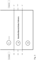
- an antibacterial cleaning or disinfection of the seat element is carried out by increasing the seat temperature to a temperature at which bacteria and germs cannot survive.
- the temperature is preferably increased to over 80°C. This allows bacteria and germs in at least one seat element to be effectively killed. This advantageously takes place without the seat being occupied. This does not require detection of the comfort parameters temperature and humidity using the comfort parameter sensors.
- a preconditioning of the seat element can take place. This means setting the comfort parameters before the seat is occupied.
- the preconditioning starts after a predeterminable start event.
- a start event can be, for example, reaching a time limit.
- the control device would comprise a time element, a clock or similar or be connected to such an element by means of signals.
- the control device then regulates or controls the comfort parameters of the seat element in the comfort range.
- the starting event can, for example, be the unlocking of the vehicle or the user approaching the vehicle, which is detected by a corresponding sensor.
- one seat element or several seat elements for example a lower seat part and a backrest element, can be operated accordingly.
- the method can be equipped with all the features already described above in the context of the device, individually or in combination with one another, and vice versa.
- the device is preferably suitable and intended to carry out the described embodiments of the method (in particular individual and/or multiple).
- step a) therefore also includes the recording of sensor data from a seat occupancy sensor.
- the control device (9) carries out an antibacterial cleaning of the seat element by activating the at least one heating device (10) so that the at least one seat element is brought to a temperature at which bacteria and germs are killed, this temperature being 80°C.
- the ventilation device is operated at the same time as the antibacterial cleaning.
- the heating device and the ventilation device can be operated alternately.
- the heating device and the ventilation device can be operated alternately.
- removing the moisture from the at least one seat element, or from the first layer of the at least one seat element bacteria are deprived of their breeding ground.
- Dehumidification is advantageously carried out by targeted heating and ventilating of the first layer.
- By advantageously alternating heating and ventilating the first layer self-cleaning or disinfection of this first layer can take place.
- the at least one heating device and the at least one ventilation device are activated at alternating intervals by the control device.
- the interval length for activation of the at least one heating device is advantageously designed such that there is essentially no change in temperature on the surface of the seat element.
- the term "essentially no change in temperature" is to be interpreted as meaning that a change in temperature is in a range that is not noticeable to the user. Such a change in temperature can therefore preferably be in a range from 0°C to 10°C, more preferably from 0°C to 5°C, more preferably from 0°C to 2.5°C, more preferably from 0°C to 1°C.
- the amount of heat introduced into the first layer is sufficient to convert a sufficient amount of moisture into steam.
- the steam generated can preferably consist of a gas phase and optionally of a liquid phase.
- the advantageous method of alternating activation of the heating device and the ventilation device at intervals is advantageously used when the humidity level is above the comfort limit. At the same time, however, the temperature value is within or above the comfort limit. This mode can remove moisture from both the seat element and the user's clothing, causing them to dry.
- the interval length can be adjusted accordingly so that a sufficient amount of heat is introduced into the seat element, or the first layer of the seat element, so that its temperature is returned to the comfort range.
- Such a comfort range of temperature is preferably between 28°C and 38°C, ideally 32 ⁇ 5°C.
- a comfort range of humidity is preferably between 10% and 85%, ideally 50% relative humidity.
- the control device activates the at least one heating device and the at least one ventilation device at alternating intervals.
- the length of the interval for activating the at least one heating device is advantageously designed such that the at least one seat element is heated to a temperature that is above a predetermined comfort range.
- the comfort range of the temperature is preferably between 28°C and 38°C. More preferably, the comfort range of the temperature is 32 ⁇ 5°C. Accordingly, in this mode, a temperature change occurs on the surface of the seat element, which is, however, irrelevant because the seat is not occupied. By using a higher temperature, more liquid passes into the gas phase, or the air in the vehicle seat will be able to absorb even more liquid. The at least one seat element can thus be brought back into the comfort range more quickly during a break in occupancy.
- preconditioning of the at least one seat element takes place, in which the comfort parameters are brought into the predetermined comfort range by activating the at least one heating device and/or the at least one ventilation device by the control device.
- the preconditioning preferably starts after a predeterminable start event.
- a start event can be, for example, reaching a time limit.
- the control device would comprise a time element, a clock or similar or be connected to such an element by means of signals.
- the control device then regulates or controls the comfort parameters of the seat element in the comfort range.
- a start event can be, for example, unlocking the vehicle, the user approaching the vehicle, which is detected by a corresponding sensor.
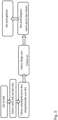
- a vehicle seat (1) comprises at least one seat element in which at least one heating device (10) and at least one ventilation device (11) are provided, wherein the vehicle seat (1) comprises a sensor device (6) which has at least one temperature sensor (7) and at least one humidity sensor (8), wherein a regulating/control device (9) controls or regulates the heating device (10) and/or the ventilation device (11) based on the data from the sensor device (6) regarding the comfort parameters, temperature and/or humidity content, whereby the seat climate can be actively controlled or regulated.
- the regulating/control device (9) has a storage device (9a) in which target values or target ranges for the comfort parameters or target values or target ranges for comfort parameter combinations are stored.
- the regulating/control device (9) compares the data provided by the sensor device (6) with the corresponding target values or target ranges.
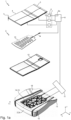
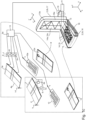
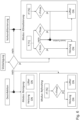
- the vehicle seat (1) comprises two seat elements (2, 2a, 2b), wherein one seat element (2a) is a lower seat part (16) and the other seat element (2, 2b) is a backrest element (17). This is shown in Figure 1b and 1c shown. In Figure 1a only one seat element (2, 2a, 2b) in the form of a lower seat part (16) is shown.
- the sensor device (6) comprises at least one temperature sensor (7) and at least one humidity sensor (8) for the lower seat part (16) and at least one temperature sensor (7a) and at least one humidity sensor (8a) for the backrest element (17).
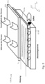
- the seat elements (2, 2a, 2b) each comprise a height direction Z, Z'.
- the height direction Z, Z' is to be understood in such a way that the uppermost layer of the seat element (2, 2a, 2b) is the one which is in contact with the user and the lowest element is the one which is furthest away from the user.
- the seat elements (2, 2a, 2b) each comprise a longitudinal direction X, X' and a width direction Y, Y'.
- the at least one seat element (2, 2a, 2b) comprises a first layer (3, 3a) which consists of a material that can absorb and pass moisture, wherein the material of the first layer (3, 3a) is porous and/or open-pored.
- a surface (4, 4a) of the first layer (3, 3a) is in direct contact with the user or in the immediate vicinity of the user when the seat is occupied. It can also be advantageous for this first layer (3) to be covered by a cover, for example a fabric cover.
- the sensor device (6) comprises at least one temperature sensor (7) and/or at least one humidity sensor (8), which is arranged in the at least one seat element (2, 2a, 2b) such that the comfort parameters temperature and/or humidity can be detected on or near the surface (4, 4a) of the at least one seat element (2, 2a, 2b).
- the at least one temperature sensor (7, 7a) and/or the at least one humidity sensor (8, 8a) is arranged in and/or above and/or below the first layer (3, 3a), wherein the regulating/control device (9) evaluates the data transmitted by the sensor device (6) depending on the distance of the respective sensor (7, 7a, 8, 8a) from the surface (4, 4a) of the at least one seat element (2, 2a, 2b) in contact with the user.
- the sensor device (6) is connected to a control device (9) for signaling purposes.
- the control device (9) controls the at least one heating device (10, 10a) and/or the at least one ventilation device (11, 11a).
- At least one heating device (10, 10a) is arranged under the first layer (3, 3a) in the height direction (Z, Z') of the seat element (2, 2a, 2b).
- the term "under" the first layer (3, 3a) is to be understood to mean that at least one heating device (10, 10a) can be arranged directly under the first layer (3, 3a) or that further layers with different functionalities and properties can be present between the first layer (3, 3a) and the at least one heating device (10, 10a).
- the at least one heating device (10, 10a) is arranged flatly, preferably over the entire surface, under the first layer (3, 3a).
- a spacer fabric (12, 12a) is arranged in the height direction (Z, Z') of the seat element (2, 2a, 2b) under the first layer (3, 3a).
- the term "under" the first layer (3, 3a) is again to be understood as meaning that the spacer fabric (12, 12a) can be arranged directly under the first layer (3, 3a) or that further layers with different functionalities and properties or the heating device (10, 10a) can be present between the first layer (3, 3a) and the spacer fabric (12, 12a).
- a shaped element (13, 13a) is arranged at least partially under the spacer fabric (12, 12a) in the height direction Z, Z' of the seat element (2, 2a, 2b).
- a shaped element (13, 13a) has a fan area (14, 14a) in which a plurality of ventilation channels (15, 15a) are provided.
- the shaped element (13, 13a) has an area (18, 18a) that borders the fan area (14, 14a). This bordering area (18, 18a) can extend along the width direction Y, Y' as well as along the longitudinal direction X, X'.
- the bordering area (18, 18a) that extends along the longitudinal direction X, X' is designed as side walls.
- the ventilation ducts (15, 15a) are connected to the ventilation device (11, 11a).
- a ventilation device (11, 11a) is provided for the lower seat part (16) and for the backrest element (17).
- Both the lower seat part (16) and the backrest element (17) are connected to just one ventilation device (11).
- a locking device (19) is advantageously provided, by means of which the respective connecting channels between the ventilation device (11) and the respective seat element (2, 2a, 2b) can be locked. With the help of this locking device (20) it can be determined which seat element (2, 2a, 2b) is ventilated. If necessary, both seat elements (2, 2a, 2b) can also be ventilated at the same time.
- the locking device (20) is connected to the control device (9) by means of signals and is controlled by it.
- the spacer fabric (12, 12a) and the fan area (14, 14a) are arranged flatly, preferably over the entire surface, under the heating device (10, 10a) or the first layer (3, 3a).
- the seat element (2, 2a, 2b) can also have further layers which are located under, above or between the above-mentioned components. These layers can can be different and also have different properties. It is also possible that the seat structure described can be put together differently in terms of location and position due to the components described.
- Two or more heating devices (10, 10a) can also be provided in the seat element (2, 2a, 2b) in order to achieve a greater distance from the surface (4, 4a) and to be able to better use the boost function described below.
- the sensor device (6) comprises a seat occupancy sensor (19) which detects the seat occupancy.
- the comfort parameters and a corresponding comfort range of a seat element (2, 2a, 2b) are shown.
- the comfort range of the temperature is advantageously in a range between 28°C and 38°C.
- the comfort range of the humidity is in a range between 50% and 80% relative humidity.
- the comfort parameters are above the comfort range of the user. If the comfort parameters are in the comfort range, state 2 is present. In a state 3, the comfort parameters are below a comfort range of the user.
- FIG 4 A possible situation in winter is shown.
- the seat is overheated due to the previous manual setting of the seat heating.
- the user therefore also overheats due to physical contact with the seat element (2, 2a, 2b). Accordingly, the user sweats.
- the moisture is absorbed by the first layer (3, 3a) of the seat element (2, 2a, 2b).
- the boost function which is described below, allows the seat element (2, 2a, 2b) to be dried quickly.
- An ideal temperature of 35.5 °C and an ideal relative humidity of 65% can thus be set.
- the seat element (2, 2a, 2b) is cold.
- the driver becomes cold due to physical contact with the seat element (2, 2a, 2b), as this transfers body heat to the seat (1).
- the seat element can be heated accordingly by the heating element (10, 10a).
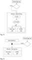
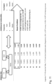
- FIG 6 a corresponding flow chart for a method for preferential operation of a seat (1) is shown in an overall overview.
- the Figures 7 to 10 show the corresponding sub-overviews.
- the procedure preferably offers the following modes: Air conditioning with boost function ( Figure 7 ), Refreshing ( Figure 8 ), cleaning ( Figure 9 ), disinfection ( Figure 9 ) and air conditioning with preconditioning ( Figure 10 ).
- the seat (1) can be advantageously cleaned by activating the heating device (10, 10a) and the ventilation device (11, 11a).
- the seat (1) can preferably be cleaned after no seat occupancy has been detected.
- the first layer (3, 3a) is advantageously heated by the heating device (10, 10a).
- the heating device (10, 10a) As a result of the heating, at least part of the moisture contained in the first layer (3, 3a) changes into the gaseous state, depending on the temperature.
- the air in the first layer (3, 3a) is heated, which can therefore absorb more moisture.
- a vapor is thus generated in the first layer (3, 3a).
- Such a vapor can ideally be a purely gaseous phase or a mixture of liquid and gaseous components.
- the ventilation device (11, 11a) preferably extracts the steam from the seat element (2, 2a, 2b) through the spacer fabric (12, 12a) and the fan area (14, 14a) or the ventilation ducts (15, 15a).
- the first layer (3, 3a) can be heated to a temperature of over 80°C. This effectively kills any bacteria present.
- the humidity sensor (8) detects a relative humidity in the first layer (3, 3a) which is above the comfort range.
- the relative humidity can be quickly regulated back to a value in the comfort range.
- the heating in turn creates steam, or steam pressure, in the seat element (2, 2a, 2b).
- this steam can be distributed in the first layer (3, 3a) and quickly sucked away.
- the "refreshing" mode is preferably carried out when the seat is not occupied.
- the first layer (3, 3a) can advantageously be heated to a higher temperature, whereby more liquid passes into the gas phase, or the air in the first layer (3, 3a) can absorb even more liquid.
- the seat element (2, 2a, 2b) can thus be quickly returned to the comfort range during a break in occupancy.
- the boost function is preferably activated when the detected relative humidity is above the comfort range or a maximum value (rFmax). At the same time, the temperature is in or above the comfort range, i.e. a maximum temperature (Tmax). These are cases F1 and F2. This boost function is intended to prevent an additional temperature increase on the surface (4, 4a) of the first layer (3, 3a).
- the heating device (10, 10a) is preferably switched on or off at predetermined intervals.
- the heating device (10, 10a) is switched on at intervals such that there is essentially no increase in temperature of the surface (4, 4a) of the first layer (3, 3a).
- the heat propagation is usually inversely proportional to the length of the heat propagation, which in this case is at the height (h) of the first layer (3, 3a).
- a heat conduction is advantageously determined from the thermal coefficient of the first layer ( ⁇ ), the temperature difference (T) between the heating element and the surface of the first layer and the height (h) as follows: ⁇ * T * 1 / h .
- the interval length is therefore preferably dimensioned such that the heating device is deactivated before a significant amount of heat reaches the surface (4, 4a) of the first layer (3, 3a).
- An interval length can therefore be dimensioned such that no significant temperature change occurs on the surface of the seat element which is perceived by the user.
- a significant temperature change is understood to mean a change of 0°C-10°C, preferably 0°C-5°C, more preferably 0°C-2.5°C, more preferably 0°C to 1°C. People perceive heat very late, ie the Surface temperature can be exceeded for a short time without the user noticing.
- the amount of heat introduced into the first layer (3, 3a) is sufficient to generate a sufficient amount of steam, which can then be extracted by the ventilation device (11, 11a).
- the ventilation device (11, 11a) By advantageously repeating the activation of the heating element several times, the moisture from the first layer (3, 3a) can be heated. A steam can thus be generated which consists of a gas phase and possibly a liquid phase. This steam can then be extracted by the ventilation device until the detected humidity value corresponds to a predetermined value in the comfort range. While the heating device (10, 10a) is activated, the ventilation device (11, 11a) can be operated continuously. It would also be conceivable for the ventilation device (11, 11a) to be activated or deactivated alternately with the heating device (10, 10a).
- the detected temperature is above the maximum temperature value (Tmax).
- the detected relative humidity is in the comfort range.
- the ventilation device (11, 11a) By activating the ventilation device (11, 11a), the temperature can be reduced accordingly. Accordingly, the heating device (10, 10a) is not activated.
- the detected temperature is above the comfort range and the detected relative humidity is below the comfort range.
- the ventilation device (11, 11a) is activated.
- the detected temperature is in the comfort range and the detected relative humidity is below the comfort range.
- the heating device (10, 10a) nor the ventilation device (11, 11a) are activated.
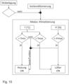
- a preconditioning of the seat element (2, 2a, 2b) can preferably take place before the seat is occupied ( Figure 10 ).
- the control device (9) regulates or controls the comfort parameters of the seat element (2, 2a, 2b) in the comfort range.
- a start event can be, for example, the unlocking of the vehicle, the user approaching the vehicle, which is detected by a corresponding sensor.
- the comfort parameters can also be set to a comfort range within a predefined time.
- the heating device (10, 10a) can be activated after the start event in order to bring the surface (4, 4a) into the comfort range.
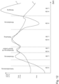
- FIG 12 shows how the comfort parameters change in the different modes by activating the heating device (10, 10a) or the ventilation device (11, 11a).
- the "Refreshing”, preconditioning and disinfection modes can also be carried out on seating elements that only have a heating device.
- preconditioning can also be carried out on a seat element (2, 2a, 2b) which only has a ventilation device (11, 11a, 11b). In this way, for example, the seat element can be cooled accordingly in summer.
Landscapes
- Engineering & Computer Science (AREA)
- Aviation & Aerospace Engineering (AREA)
- Transportation (AREA)
- Mechanical Engineering (AREA)
- Chair Legs, Seat Parts, And Backrests (AREA)
Claims (15)
- Siège de véhicule (1) comportant au moins un élément de siège (2, 2a, 2b), dans lequel sont disposés au moins un dispositif de chauffage (10, 10a) et au moins un dispositif de ventilation (11, 11a), dans lequel le siège de véhicule (1) comporte un dispositif de détection (6), lequel présente au moins un capteur de température (7, 7a) et au moins un capteur d'humidité (8, 8a), dans lequel un dispositif de régulation/de commande (9) commande ou régule le dispositif de chauffage (10, 10a) et/ou le dispositif de ventilation (11, 11a) à l'aide des données provenant du dispositif de détection (6) en ce qui concerne les paramètres de confort que sont la température et/ou la teneur en humidité, ce par quoi la climatisation du siège est commandable ou régulable activement,
caractérisé par le fait que ledit au moins un élément de siège (2, 2a, 2b) comporte une première couche (3, 3a), laquelle est constituée d'un matériau qui peut absorber et évacuer l'humidité, le matériau de la première couche (3, 3a) étant poreux et/ou à pores ouverts, ledit au moins un élément de siège (2, 2a, 2b) étant apte à être chauffé par au moins un dispositif de chauffage (10, 10a), ce par quoi une humidité absorbée dans la première couche (3, 3a) passe au moins dans un état gazeux et l'air se trouvant dans l'élément de siège (2, 2a, 2b) se réchauffe, la vapeur produite par le chauffage étant apte à être transportée hors de l'élément de siège (2, 2a, 2b) au moyen du dispositif de ventilation, la vapeur étant aspirée hors de l'élément de siège (2, 2a, 2b) au moyen du dispositif de ventilation (11, 11a). - Siège de véhicule (1) selon la revendication 1,
caractérisé par le fait que
le dispositif de régulation/de commande (9) présente un dispositif de stockage (9a) dans lequel sont stockées des valeurs cibles ou des plages cibles pour les paramètres de confort ou des valeurs cibles ou des plages cibles pour des combinaisons de paramètres de confort, le dispositif de régulation/de commande (9) comparant les données fournies par le dispositif de détection (6) avec les valeurs cibles ou plages cibles correspondantes. - Siège de véhicule (1) selon l'une des revendications 1 ou 2,
caractérisé par le fait que
le siège de véhicule (1) comporte deux éléments de siège (2, 2a, 2b), un élément de siège (2a) étant une partie siège inférieure (16) et l'autre élément de siège (2, 2b) étant un élément dossier (17), le dispositif de détection (6) comportant au moins un capteur de température (7) et au moins un capteur d'humidité (8) pour la partie siège inférieure (16) et au moins un capteur de température (7a) et au moins un capteur d'humidité (8a) pour l'élément dossier (17). - Siège de véhicule selon l'une des revendications précédentes,
caractérisé par le fait que
lorsque le siège est occupé, une surface (4, 4a) de la première couche (3, 3a) est en contact direct avec l'utilisateur ou à proximité immédiate de l'utilisateur. - Siège de véhicule selon l'une des revendications précédentes,
caractérisé par le fait que
ledit au moins un capteur de température (7, 7a) et/ou ledit au moins un capteur d'humidité (8, 8a) sont disposés dans ledit au moins un élément de siège (2, 2a, 2b) de telle sorte que les paramètres de confort que sont la température et/ou l'humidité sont détectables sur ou à proximité de la surface (4, 4a) dudit au moins un élément de siège (2, 2a, 2b), ledit au moins un capteur de température (7, 7a) et/ou ledit au moins un capteur d'humidité (8, 8a) étant disposé(s) dans et/ou sur et/ou sous la première couche (3, 3a), le dispositif de régulation/de commande (9) évaluant les données transmises par le dispositif de détection (6) en fonction de la distance du capteur respectif (7, 7a, 8, 8a) à la surface (4, 4a), en contact avec l'utilisateur, dudit au moins un élément de siège (2, 2a, 2b). - Siège de véhicule selon l'une des revendications 4 et 5,
caractérisé par le fait que
dans la direction de la hauteur (Z, Z') dudit au moins un élément de siège (2, 2a, 2b), un tissu d'espacement (12, 12a) est disposé sous la première couche (3, 3a), un dispositif de chauffage (10, 10a) étant disposé entre la première couche ( 3, 3a) et le tissu d'espacement (12, 12a). - Siège de véhicule selon la revendication 6,
caractérisé par le fait que
dans la direction de la hauteur (Z, Z') dudit au moins un élément de siège (2, 2a, 2b), un élément façonné (13, 13a) est disposé au moins par sections sous le tissu d'espacement (12, 12a), lequel élément façonné présente une zone de ventilation (14, 14a) dans laquelle une pluralité de canaux de ventilation (15, 15a) est prévue, les canaux de ventilation (15, 15a) étant reliés audit au moins un dispositif de ventilation (11, 11a), l'élément façonné (13, 13a) présentant une zone (18, 18a) bordant la zone de ventilation (14, 14a). - Siège de véhicule (1) selon l'une des revendications précédentes,
caractérisé par le fait que
le changement d'état physique conduit, en raison de la chaleur d'évaporation à appliquer, à un refroidissement de la surface de l'élément de siège (2, 2a, 2b), une pression différentielle prédominant en ce qui concerne le volume d'air environnant en raison de la température augmentée de la vapeur, laquelle pression facilite le retrait de la vapeur. - Siège de véhicule selon l'une des revendications précédentes,
caractérisé par le fait que
le dispositif de détection (6) comporte un capteur d'occupation de siège (19), lequel détecte l'occupation du siège. - Siège de véhicule selon l'une des revendications précédentes,
caractérisé par le fait que
la régulation de la climatisation du siège s'effectue par chauffage et ventilation en alternancs de la première couche (3, 3a), ledit au moins un dispositif de chauffage (10, 10a) et/ou ledit au moins un dispositif de ventilation (11, 11a) étant activables ou désactivables à intervalles prédéfinis, ledit au moins un dispositif de chauffage (10, 10a) étant commutable à intervalles de telle sorte qu'il n'y a sensiblement pas de changement de température à la surface (4, 4a) de l'élément de siège (2, 2a, 2b). - Procédé de fonctionnement d'un siège de véhicule (1), en particulier d'un siège de véhicule selon l'une des revendications précédentes 1 à 9, dans lequel le siège de véhicule (1) comporte au moins un élément de siège (2), dans lequel sont disposés au moins un dispositif de chauffage (10) et au moins un dispositif de ventilation (11), le procédé comportant les étapes suivantes :a) Saisie de données de détection par le dispositif de détection (6), lequel présente au moins un capteur de température (7) et au moins un capteur d'humidité (8) ;b) Comparaison facultative par le dispositif de régulation/de commande (9) des données de détection saisies avec des valeurs cibles prédéfinies ;c) Activation d'au moins un dispositif de chauffage (10, 10a) et/ou d'au moins un dispositif de ventilation (11, 11a) par le dispositif de régulation/de commande (9), ledit au moins un élément de siège (2, 2a, 2b) comportant une première couche (3, 3a), laquelle est constituée d'un matériau qui peut absorber et évacuer l'humidité et le matériau de la première couche (3, 3a) étant réalisé poreux et/ou à pores ouverts, ledit au moins un élément de siège (2, 2a, 2b) étant apte à être chauffé par au moins un dispositif de chauffage (10, 10a), ce par quoi une humidité absorbée dans la première couche (3, 3a) passe au moins dans un état gazeux et l'air se trouvant dans l'élément de siège (2, 2a, 2b) se réchauffe, la vapeur produite par le chauffage étant apte à être transportée hors de l'élément de siège (2, 2a, 2b) au moyen du dispositif de ventilation, la vapeur étant aspirée hors de l'élément de siège (2, 2a, 2b) au moyen du dispositif de ventilation (11, 11a).
- Procédé selon la revendication 11,
caractérisé par le fait que
lorsque le siège n'est pas occupé, le dispositif de régulation/de commande (9) effectue un nettoyage antibactérien de l'élément de siège, dans lequel ledit au moins un dispositif de chauffage (10) est commandé, de telle sorte que ledit au moins un élément de siège est amené à une température à laquelle les bactéries et les germes sont tués, cette température étant supérieure à 80°C. - Procédé selon l'une des revendications 11 et 12,
caractérisé par le fait que
lorsque le siège est occupé, ledit au moins un dispositif de chauffage (10, 10a) et ledit au moins un dispositif de ventilation (11, 11a) sont activés par le dispositif de régulation/de commande (9) à intervalles alternés, la longueur d'intervalle pour une activation dudit au moins un dispositif de chauffage (10, 10a) étant conçue de telle sorte qu'il n'y a sensiblement pas de changement de température sur la surface (4, 4a) de l'élément de siège (2, 2a, 2b). - Procédé selon l'une des revendications 11 à 13,
caractérisé par le fait que
lorsque le siège n'est pas occupé, ledit au moins un dispositif de chauffage (10, 10a) et ledit au moins un dispositif de ventilation (11, 11a) sont activés par le dispositif de régulation/de commande (9) à intervalles alternés, la longueur d'intervalle pour une activation dudit au moins un dispositif de chauffage (10, 10a) étant conçue de telle sorte que ledit au moins un élément de siège est chauffé à une température qui est supérieure à une plage de confort prédéterminée, la plage de confort de la température étant entre 28°C et 38°C. - Procédé selon l'une des revendications 11 à 14,
caractérisé par le fait que
lors de l'apparition d'un événement de démarrage prédéfini, a lieu un préconditionnement dudit au moins un élément de siège (2, 2a, 2b), dans lequel les paramètres de confort sont amenés dans la plage de confort prédéfinie par l'activation dudit au moins un dispositif de chauffage (10, 10a) et/ou dudit au moins un dispositif de ventilation (11, 11a) par le dispositif de régulation/de commande (9).
Applications Claiming Priority (3)
| Application Number | Priority Date | Filing Date | Title |
|---|---|---|---|
| DE102018120996 | 2018-08-28 | ||
| DE102019122278.8A DE102019122278A1 (de) | 2018-08-28 | 2019-08-20 | Fahrzeugsitz und ein Verfahren zum Betrieb eines Fahrzeugsitzes |
| PCT/EP2019/072748 WO2020043679A1 (fr) | 2018-08-28 | 2019-08-27 | Siège de véhicule et procédé servant à faire fonctionner un siège de véhicule |
Publications (2)
| Publication Number | Publication Date |
|---|---|
| EP3844021A1 EP3844021A1 (fr) | 2021-07-07 |
| EP3844021B1 true EP3844021B1 (fr) | 2025-01-15 |
Family
ID=69526877
Family Applications (1)
| Application Number | Title | Priority Date | Filing Date |
|---|---|---|---|
| EP19759363.5A Active EP3844021B1 (fr) | 2018-08-28 | 2019-08-27 | Siège de véhicule et procédé servant à faire fonctionner un siège de véhicule |
Country Status (5)
| Country | Link |
|---|---|
| US (1) | US12351089B2 (fr) |
| EP (1) | EP3844021B1 (fr) |
| CN (1) | CN112654528B (fr) |
| DE (1) | DE102019122278A1 (fr) |
| WO (1) | WO2020043679A1 (fr) |
Families Citing this family (8)
| Publication number | Priority date | Publication date | Assignee | Title |
|---|---|---|---|---|
| JP7264074B2 (ja) * | 2020-01-29 | 2023-04-25 | 株式会社デンソー | シート空調装置 |
| JP7409238B2 (ja) * | 2020-06-30 | 2024-01-09 | 株式会社デンソー | シート空調装置 |
| IT202000019726A1 (it) * | 2020-08-07 | 2022-02-07 | Iveco France Sas | Sistema di sedile per un veicolo per il trasporto in comune di passeggeri comprendente un sistema di igienizzazione |
| US12325337B2 (en) | 2021-04-30 | 2025-06-10 | Faurecia Automotive Seating, Llc | Occupant support surface heater |
| JP7773924B2 (ja) * | 2022-02-25 | 2025-11-20 | 日本発條株式会社 | 車両用シート |
| CN115923722B (zh) * | 2022-12-19 | 2024-12-17 | 北京北汽李尔汽车系统有限公司 | 一种汽车座椅自动清洁方法、装置以及汽车 |
| US12263769B2 (en) | 2023-06-23 | 2025-04-01 | Faurecia Automotive Seating, Llc | Method of manufacturing a heat mat |
| US12358405B2 (en) | 2023-06-23 | 2025-07-15 | Faurecia Automotive Seating, Llc | Heat mat for vehicle seat |
Family Cites Families (17)
| Publication number | Priority date | Publication date | Assignee | Title |
|---|---|---|---|---|
| DE19703516C1 (de) | 1997-01-31 | 1998-05-07 | Daimler Benz Ag | Fahrzeugsitz |
| DE19726810C1 (de) | 1997-06-25 | 1998-10-22 | Klaus Doerr | Klimasitz |
| FR2790430B1 (fr) | 1999-03-01 | 2001-05-18 | Faure Bertrand Equipements Sa | Procede et systeme de regulation thermique de siege de vehicule |
| SE0002690L (sv) | 2000-07-19 | 2002-01-20 | Kongsberg Automotive Ab | Anordning och förfarande för temperaturreglering och ventilering av ett säte |
| DE20112473U1 (de) | 2001-07-28 | 2002-12-19 | Johnson Controls GmbH, 51399 Burscheid | Klimatisiertes Polsterteil für einen Fahrzeugsitz |
| US20060244289A1 (en) * | 2005-04-02 | 2006-11-02 | Johnson Controls Technology Company | Control system for seat |
| EP1820690B1 (fr) * | 2006-02-21 | 2009-04-15 | Ford Global Technologies, LLC | Système de siège de véhicule |
| DE112013004698T5 (de) | 2012-09-25 | 2015-07-09 | Faurecia Automotive Seating, Llc | Fahrzeugsitz mit einer thermischen Vorrichtung |
| CN202911595U (zh) * | 2012-11-06 | 2013-05-01 | 无锡职业技术学院 | 汽车座椅的自动温、湿度控制装置 |
| DE102013003673A1 (de) * | 2013-03-02 | 2014-03-20 | Daimler Ag | Polsterteil für eine Sitzanlage eines Kraftwagens |
| FR3010355B1 (fr) * | 2013-09-09 | 2017-04-21 | Faurecia Sieges Automobile | Siege de vehicule automobile et procede de gestion du confort d'un tel siege de vehicule automobile |
| CN103587446A (zh) | 2013-11-01 | 2014-02-19 | 安徽工贸职业技术学院 | 一种汽车坐具 |
| US10589647B2 (en) * | 2013-12-05 | 2020-03-17 | Gentherm Incorporated | Systems and methods for climate controlled seats |
| EP2910413A1 (fr) * | 2014-02-25 | 2015-08-26 | Sensirion AG | Ensemble de siège muni d'un capteur de température ou d'humidité |
| DE102016219203B4 (de) * | 2016-10-04 | 2025-03-13 | Volkswagen Aktiengesellschaft | Verfahren zur Klimatisierung eines Fahrzeugsitzes und Fahrzeug mit einem derart klimatisierten Fahrzeugsitz |
| CN110235518B (zh) * | 2017-02-01 | 2021-07-20 | 松下知识产权经营株式会社 | 座椅加热器 |
| US10668845B2 (en) * | 2018-04-25 | 2020-06-02 | GM Global Technology Operations LLC | Moisture detection and regulation in a vehicle interior component |
-
2019
- 2019-08-20 DE DE102019122278.8A patent/DE102019122278A1/de active Pending
- 2019-08-27 US US17/271,777 patent/US12351089B2/en active Active
- 2019-08-27 CN CN201980055712.4A patent/CN112654528B/zh active Active
- 2019-08-27 EP EP19759363.5A patent/EP3844021B1/fr active Active
- 2019-08-27 WO PCT/EP2019/072748 patent/WO2020043679A1/fr not_active Ceased
Also Published As
| Publication number | Publication date |
|---|---|
| WO2020043679A1 (fr) | 2020-03-05 |
| EP3844021A1 (fr) | 2021-07-07 |
| CN112654528B (zh) | 2023-08-22 |
| US20210323453A1 (en) | 2021-10-21 |
| CN112654528A (zh) | 2021-04-13 |
| US12351089B2 (en) | 2025-07-08 |
| DE102019122278A1 (de) | 2020-03-05 |
Similar Documents
| Publication | Publication Date | Title |
|---|---|---|
| EP3844021B1 (fr) | Siège de véhicule et procédé servant à faire fonctionner un siège de véhicule | |
| DE69425156T2 (de) | Klimaregelsystem für einen sitz mit veränderlicher temperatur | |
| DE10238552A1 (de) | System und Verfahren für die Klimaregelung in Fahrzeugen | |
| DE112014005563T5 (de) | Systeme und Verfahren für klimatisierte Sitze | |
| DE102016108732A1 (de) | Verbesserter Klimasitz mit System und Verfahren zum asymmetrischem Wärmemanagement | |
| EP1708900A1 (fr) | Procede pour reguler des buses d'air servant a la climatisation d'un vehicule automobile | |
| DE102016008165A1 (de) | Vorrichtung mit einem Klima-Cocoon und Klima-Cocoon | |
| EP3269571B1 (fr) | Procédé de fonctionnement d'un système de climatisation d'un habitacle d'un véhicule automobile | |
| DE19711031B4 (de) | Heizungs-, Lüftungs- und/oder Klimaanlage mit Leistungsregelung, insbesondere für Kraftfahrzeuge | |
| DE19953385A1 (de) | Verfahren und Vorrichtung zur Steuerung einer Einrichtung zur Klimatisierung eines Fahrzeugsitzes sowie Bedieneinrichtung dafür | |
| DE102016219203B4 (de) | Verfahren zur Klimatisierung eines Fahrzeugsitzes und Fahrzeug mit einem derart klimatisierten Fahrzeugsitz | |
| DE102011121053A1 (de) | Temperaturregelung von beheizten Luftverteilungssystemen in Passagierräumen | |
| DE10026656A1 (de) | Verfahren und Vorrichtung zum Klimatisieren eines Sitzes eines Kraftfahrzeugs | |
| EP3713788B1 (fr) | Système de climatisation d'un siège de véhicule ayant un fonctionnement optimisé en matière de confort en commutant le système de ventilation du siège selon les besoins | |
| DE102019212803A1 (de) | Komponente, insbesondere Fahrzeugsitz oder Bekleidungsstück mit einer thermischen Komfortregelung, die mit einer Massageeinrichtung gekoppelt ist | |
| DE102009013258A1 (de) | Polster für einen Fahrzeugsitz | |
| DE102016225020B4 (de) | Verfahren und Vorrichtung zum Starten eines Luftaustauschbetriebs | |
| DE102017005702A1 (de) | Verfahren zum Steuern einer Belüftungseinrichtung eines Fahrzeugsitzes | |
| EP1270287B1 (fr) | Procédé de réglage de la température intérieure d'un habitacle de véhicule et dispositif de chauffage ou de climatisation pour véhicule | |
| DE10324571B3 (de) | Fahrzeug-Heiz- und/oder Klimaanlage und Verfahren zur Heiz- und/oder Klimatisierungsregelung in Fahrzeugen | |
| DE10116345B4 (de) | Verfahren zur Regelung der Heizung eines klimatisierten Sitzes | |
| DE102016215392A1 (de) | Verfahren zum Unterbinden einer Fußraumbelüftung einzelner Sitzplätze eines Fahrzeuges und Vorrichtung zur Ausführung des Verfahrens | |
| DE102007033222B4 (de) | Verfahren und Vorrichtung zum Steuern oder Regeln einer Sitzheizung | |
| DE19948735A1 (de) | Verfahren und Einrichtung zur Klimatisierung von Fahrzeugsitzen | |
| DE112023002671T5 (de) | Konditionierungssystem für thermische Effektoren |
Legal Events
| Date | Code | Title | Description |
|---|---|---|---|
| STAA | Information on the status of an ep patent application or granted ep patent |
Free format text: STATUS: UNKNOWN |
|
| STAA | Information on the status of an ep patent application or granted ep patent |
Free format text: STATUS: THE INTERNATIONAL PUBLICATION HAS BEEN MADE |
|
| STAA | Information on the status of an ep patent application or granted ep patent |
Free format text: STATUS: REQUEST FOR EXAMINATION WAS MADE |
|
| PUAI | Public reference made under article 153(3) epc to a published international application that has entered the european phase |
Free format text: ORIGINAL CODE: 0009012 |
|
| 17P | Request for examination filed |
Effective date: 20210319 |
|
| AK | Designated contracting states |
Kind code of ref document: A1 Designated state(s): AL AT BE BG CH CY CZ DE DK EE ES FI FR GB GR HR HU IE IS IT LI LT LU LV MC MK MT NL NO PL PT RO RS SE SI SK SM TR |
|
| DAV | Request for validation of the european patent (deleted) | ||
| DAX | Request for extension of the european patent (deleted) | ||
| STAA | Information on the status of an ep patent application or granted ep patent |
Free format text: STATUS: EXAMINATION IS IN PROGRESS |
|
| 17Q | First examination report despatched |
Effective date: 20230207 |
|
| GRAP | Despatch of communication of intention to grant a patent |
Free format text: ORIGINAL CODE: EPIDOSNIGR1 |
|
| STAA | Information on the status of an ep patent application or granted ep patent |
Free format text: STATUS: GRANT OF PATENT IS INTENDED |
|
| INTG | Intention to grant announced |
Effective date: 20240913 |
|
| GRAS | Grant fee paid |
Free format text: ORIGINAL CODE: EPIDOSNIGR3 |
|
| GRAA | (expected) grant |
Free format text: ORIGINAL CODE: 0009210 |
|
| STAA | Information on the status of an ep patent application or granted ep patent |
Free format text: STATUS: THE PATENT HAS BEEN GRANTED |
|
| AK | Designated contracting states |
Kind code of ref document: B1 Designated state(s): AL AT BE BG CH CY CZ DE DK EE ES FI FR GB GR HR HU IE IS IT LI LT LU LV MC MK MT NL NO PL PT RO RS SE SI SK SM TR |
|
| REG | Reference to a national code |
Ref country code: CH Ref legal event code: EP Ref country code: GB Ref legal event code: FG4D Free format text: NOT ENGLISH |
|
| REG | Reference to a national code |
Ref country code: DE Ref legal event code: R096 Ref document number: 502019012821 Country of ref document: DE |
|
| REG | Reference to a national code |
Ref country code: IE Ref legal event code: FG4D Free format text: LANGUAGE OF EP DOCUMENT: GERMAN |
|
| REG | Reference to a national code |
Ref country code: NL Ref legal event code: MP Effective date: 20250115 |
|
| PG25 | Lapsed in a contracting state [announced via postgrant information from national office to epo] |
Ref country code: NL Free format text: LAPSE BECAUSE OF FAILURE TO SUBMIT A TRANSLATION OF THE DESCRIPTION OR TO PAY THE FEE WITHIN THE PRESCRIBED TIME-LIMIT Effective date: 20250115 |
|
| PG25 | Lapsed in a contracting state [announced via postgrant information from national office to epo] |
Ref country code: RS Free format text: LAPSE BECAUSE OF FAILURE TO SUBMIT A TRANSLATION OF THE DESCRIPTION OR TO PAY THE FEE WITHIN THE PRESCRIBED TIME-LIMIT Effective date: 20250415 |
|
| PG25 | Lapsed in a contracting state [announced via postgrant information from national office to epo] |
Ref country code: FI Free format text: LAPSE BECAUSE OF FAILURE TO SUBMIT A TRANSLATION OF THE DESCRIPTION OR TO PAY THE FEE WITHIN THE PRESCRIBED TIME-LIMIT Effective date: 20250115 |
|
| PG25 | Lapsed in a contracting state [announced via postgrant information from national office to epo] |
Ref country code: PL Free format text: LAPSE BECAUSE OF FAILURE TO SUBMIT A TRANSLATION OF THE DESCRIPTION OR TO PAY THE FEE WITHIN THE PRESCRIBED TIME-LIMIT Effective date: 20250115 |
|
| PG25 | Lapsed in a contracting state [announced via postgrant information from national office to epo] |
Ref country code: ES Free format text: LAPSE BECAUSE OF FAILURE TO SUBMIT A TRANSLATION OF THE DESCRIPTION OR TO PAY THE FEE WITHIN THE PRESCRIBED TIME-LIMIT Effective date: 20250115 |
|
| REG | Reference to a national code |
Ref country code: LT Ref legal event code: MG9D |
|
| PG25 | Lapsed in a contracting state [announced via postgrant information from national office to epo] |
Ref country code: NO Free format text: LAPSE BECAUSE OF FAILURE TO SUBMIT A TRANSLATION OF THE DESCRIPTION OR TO PAY THE FEE WITHIN THE PRESCRIBED TIME-LIMIT Effective date: 20250415 Ref country code: IS Free format text: LAPSE BECAUSE OF FAILURE TO SUBMIT A TRANSLATION OF THE DESCRIPTION OR TO PAY THE FEE WITHIN THE PRESCRIBED TIME-LIMIT Effective date: 20250515 |
|
| PG25 | Lapsed in a contracting state [announced via postgrant information from national office to epo] |
Ref country code: HR Free format text: LAPSE BECAUSE OF FAILURE TO SUBMIT A TRANSLATION OF THE DESCRIPTION OR TO PAY THE FEE WITHIN THE PRESCRIBED TIME-LIMIT Effective date: 20250115 |
|
| PG25 | Lapsed in a contracting state [announced via postgrant information from national office to epo] |
Ref country code: PT Free format text: LAPSE BECAUSE OF FAILURE TO SUBMIT A TRANSLATION OF THE DESCRIPTION OR TO PAY THE FEE WITHIN THE PRESCRIBED TIME-LIMIT Effective date: 20250515 Ref country code: LV Free format text: LAPSE BECAUSE OF FAILURE TO SUBMIT A TRANSLATION OF THE DESCRIPTION OR TO PAY THE FEE WITHIN THE PRESCRIBED TIME-LIMIT Effective date: 20250115 |
|
| PG25 | Lapsed in a contracting state [announced via postgrant information from national office to epo] |
Ref country code: BG Free format text: LAPSE BECAUSE OF FAILURE TO SUBMIT A TRANSLATION OF THE DESCRIPTION OR TO PAY THE FEE WITHIN THE PRESCRIBED TIME-LIMIT Effective date: 20250115 Ref country code: GR Free format text: LAPSE BECAUSE OF FAILURE TO SUBMIT A TRANSLATION OF THE DESCRIPTION OR TO PAY THE FEE WITHIN THE PRESCRIBED TIME-LIMIT Effective date: 20250416 |
|
| PG25 | Lapsed in a contracting state [announced via postgrant information from national office to epo] |
Ref country code: SE Free format text: LAPSE BECAUSE OF FAILURE TO SUBMIT A TRANSLATION OF THE DESCRIPTION OR TO PAY THE FEE WITHIN THE PRESCRIBED TIME-LIMIT Effective date: 20250115 |
|
| PG25 | Lapsed in a contracting state [announced via postgrant information from national office to epo] |
Ref country code: SM Free format text: LAPSE BECAUSE OF FAILURE TO SUBMIT A TRANSLATION OF THE DESCRIPTION OR TO PAY THE FEE WITHIN THE PRESCRIBED TIME-LIMIT Effective date: 20250115 |
|
| PG25 | Lapsed in a contracting state [announced via postgrant information from national office to epo] |
Ref country code: DK Free format text: LAPSE BECAUSE OF FAILURE TO SUBMIT A TRANSLATION OF THE DESCRIPTION OR TO PAY THE FEE WITHIN THE PRESCRIBED TIME-LIMIT Effective date: 20250115 |
|
| PGFP | Annual fee paid to national office [announced via postgrant information from national office to epo] |
Ref country code: DE Payment date: 20250819 Year of fee payment: 7 |
|
| PGFP | Annual fee paid to national office [announced via postgrant information from national office to epo] |
Ref country code: GB Payment date: 20250822 Year of fee payment: 7 |
|
| REG | Reference to a national code |
Ref country code: DE Ref legal event code: R097 Ref document number: 502019012821 Country of ref document: DE |
|
| PG25 | Lapsed in a contracting state [announced via postgrant information from national office to epo] |
Ref country code: CZ Free format text: LAPSE BECAUSE OF FAILURE TO SUBMIT A TRANSLATION OF THE DESCRIPTION OR TO PAY THE FEE WITHIN THE PRESCRIBED TIME-LIMIT Effective date: 20250115 Ref country code: EE Free format text: LAPSE BECAUSE OF FAILURE TO SUBMIT A TRANSLATION OF THE DESCRIPTION OR TO PAY THE FEE WITHIN THE PRESCRIBED TIME-LIMIT Effective date: 20250115 |
|
| PG25 | Lapsed in a contracting state [announced via postgrant information from national office to epo] |
Ref country code: RO Free format text: LAPSE BECAUSE OF FAILURE TO SUBMIT A TRANSLATION OF THE DESCRIPTION OR TO PAY THE FEE WITHIN THE PRESCRIBED TIME-LIMIT Effective date: 20250115 |
|
| PG25 | Lapsed in a contracting state [announced via postgrant information from national office to epo] |
Ref country code: SK Free format text: LAPSE BECAUSE OF FAILURE TO SUBMIT A TRANSLATION OF THE DESCRIPTION OR TO PAY THE FEE WITHIN THE PRESCRIBED TIME-LIMIT Effective date: 20250115 |
|
| PLBE | No opposition filed within time limit |
Free format text: ORIGINAL CODE: 0009261 |
|
| STAA | Information on the status of an ep patent application or granted ep patent |
Free format text: STATUS: NO OPPOSITION FILED WITHIN TIME LIMIT |
|
| REG | Reference to a national code |
Ref country code: CH Ref legal event code: L10 Free format text: ST27 STATUS EVENT CODE: U-0-0-L10-L00 (AS PROVIDED BY THE NATIONAL OFFICE) Effective date: 20251126 |
|
| 26N | No opposition filed |
Effective date: 20251016 |
|
| REG | Reference to a national code |
Ref country code: CH Ref legal event code: H13 Free format text: ST27 STATUS EVENT CODE: U-0-0-H10-H13 (AS PROVIDED BY THE NATIONAL OFFICE) Effective date: 20260324 |
|
| PG25 | Lapsed in a contracting state [announced via postgrant information from national office to epo] |
Ref country code: MC Free format text: LAPSE BECAUSE OF FAILURE TO SUBMIT A TRANSLATION OF THE DESCRIPTION OR TO PAY THE FEE WITHIN THE PRESCRIBED TIME-LIMIT Effective date: 20250115 |
|
| PG25 | Lapsed in a contracting state [announced via postgrant information from national office to epo] |
Ref country code: LU Free format text: LAPSE BECAUSE OF NON-PAYMENT OF DUE FEES Effective date: 20250827 |
|
| PGFP | Annual fee paid to national office [announced via postgrant information from national office to epo] |
Ref country code: IT Payment date: 20251231 Year of fee payment: 7 |