EP3844038B1 - Dispositif de freinage régénératif basé sur un engrenage de transmission épicycloïdal et un frein à disque - Google Patents
Dispositif de freinage régénératif basé sur un engrenage de transmission épicycloïdal et un frein à disque Download PDFInfo
- Publication number
- EP3844038B1 EP3844038B1 EP18931698.7A EP18931698A EP3844038B1 EP 3844038 B1 EP3844038 B1 EP 3844038B1 EP 18931698 A EP18931698 A EP 18931698A EP 3844038 B1 EP3844038 B1 EP 3844038B1
- Authority
- EP
- European Patent Office
- Prior art keywords
- gear
- regenerative braking
- rotation
- epicyclic transmission
- braking device
- Prior art date
- Legal status (The legal status is an assumption and is not a legal conclusion. Google has not performed a legal analysis and makes no representation as to the accuracy of the status listed.)
- Active
Links
Images



Classifications
-
- F—MECHANICAL ENGINEERING; LIGHTING; HEATING; WEAPONS; BLASTING
- F16—ENGINEERING ELEMENTS AND UNITS; GENERAL MEASURES FOR PRODUCING AND MAINTAINING EFFECTIVE FUNCTIONING OF MACHINES OR INSTALLATIONS; THERMAL INSULATION IN GENERAL
- F16D—COUPLINGS FOR TRANSMITTING ROTATION; CLUTCHES; BRAKES
- F16D61/00—Brakes with means for making the energy absorbed available for use
-
- B—PERFORMING OPERATIONS; TRANSPORTING
- B60—VEHICLES IN GENERAL
- B60T—VEHICLE BRAKE CONTROL SYSTEMS OR PARTS THEREOF; BRAKE CONTROL SYSTEMS OR PARTS THEREOF, IN GENERAL; ARRANGEMENT OF BRAKING ELEMENTS ON VEHICLES IN GENERAL; PORTABLE DEVICES FOR PREVENTING UNWANTED MOVEMENT OF VEHICLES; VEHICLE MODIFICATIONS TO FACILITATE COOLING OF BRAKES
- B60T1/00—Arrangements of braking elements, i.e. of those parts where braking effect occurs specially for vehicles
- B60T1/02—Arrangements of braking elements, i.e. of those parts where braking effect occurs specially for vehicles acting by retarding wheels
- B60T1/10—Arrangements of braking elements, i.e. of those parts where braking effect occurs specially for vehicles acting by retarding wheels by utilising wheel movement for accumulating energy, e.g. driving air compressors
-
- B—PERFORMING OPERATIONS; TRANSPORTING
- B60—VEHICLES IN GENERAL
- B60B—VEHICLE WHEELS; CASTORS; AXLES FOR WHEELS OR CASTORS; INCREASING WHEEL ADHESION
- B60B27/00—Hubs
- B60B27/0047—Hubs characterised by functional integration of other elements
-
- B—PERFORMING OPERATIONS; TRANSPORTING
- B60—VEHICLES IN GENERAL
- B60B—VEHICLE WHEELS; CASTORS; AXLES FOR WHEELS OR CASTORS; INCREASING WHEEL ADHESION
- B60B27/00—Hubs
- B60B27/0047—Hubs characterised by functional integration of other elements
- B60B27/0052—Hubs characterised by functional integration of other elements the element being a brake disc
-
- B—PERFORMING OPERATIONS; TRANSPORTING
- B60—VEHICLES IN GENERAL
- B60B—VEHICLE WHEELS; CASTORS; AXLES FOR WHEELS OR CASTORS; INCREASING WHEEL ADHESION
- B60B27/00—Hubs
- B60B27/02—Hubs adapted to be rotatably arranged on axle
- B60B27/023—Hubs adapted to be rotatably arranged on axle specially adapted for bicycles
-
- B—PERFORMING OPERATIONS; TRANSPORTING
- B62—LAND VEHICLES FOR TRAVELLING OTHERWISE THAN ON RAILS
- B62L—BRAKES SPECIALLY ADAPTED FOR CYCLES
- B62L1/00—Brakes; Arrangements thereof
- B62L1/005—Brakes; Arrangements thereof constructional features of brake elements, e.g. fastening of brake blocks in their holders
-
- F—MECHANICAL ENGINEERING; LIGHTING; HEATING; WEAPONS; BLASTING
- F16—ENGINEERING ELEMENTS AND UNITS; GENERAL MEASURES FOR PRODUCING AND MAINTAINING EFFECTIVE FUNCTIONING OF MACHINES OR INSTALLATIONS; THERMAL INSULATION IN GENERAL
- F16D—COUPLINGS FOR TRANSMITTING ROTATION; CLUTCHES; BRAKES
- F16D67/00—Combinations of couplings and brakes; Combinations of clutches and brakes
- F16D67/02—Clutch-brake combinations
-
- F—MECHANICAL ENGINEERING; LIGHTING; HEATING; WEAPONS; BLASTING
- F16—ENGINEERING ELEMENTS AND UNITS; GENERAL MEASURES FOR PRODUCING AND MAINTAINING EFFECTIVE FUNCTIONING OF MACHINES OR INSTALLATIONS; THERMAL INSULATION IN GENERAL
- F16D—COUPLINGS FOR TRANSMITTING ROTATION; CLUTCHES; BRAKES
- F16D7/00—Slip couplings, e.g. slipping on overload, for absorbing shock
- F16D7/02—Slip couplings, e.g. slipping on overload, for absorbing shock of the friction type
-
- F—MECHANICAL ENGINEERING; LIGHTING; HEATING; WEAPONS; BLASTING
- F16—ENGINEERING ELEMENTS AND UNITS; GENERAL MEASURES FOR PRODUCING AND MAINTAINING EFFECTIVE FUNCTIONING OF MACHINES OR INSTALLATIONS; THERMAL INSULATION IN GENERAL
- F16H—GEARING
- F16H57/00—General details of gearing
- F16H57/08—General details of gearing of gearings with members having orbital motion
- F16H57/10—Braking arrangements
-
- B—PERFORMING OPERATIONS; TRANSPORTING
- B62—LAND VEHICLES FOR TRAVELLING OTHERWISE THAN ON RAILS
- B62L—BRAKES SPECIALLY ADAPTED FOR CYCLES
- B62L3/00—Brake-actuating mechanisms; Arrangements thereof
- B62L3/02—Brake-actuating mechanisms; Arrangements thereof for control by a hand lever
-
- F—MECHANICAL ENGINEERING; LIGHTING; HEATING; WEAPONS; BLASTING
- F03—MACHINES OR ENGINES FOR LIQUIDS; WIND, SPRING, OR WEIGHT MOTORS; PRODUCING MECHANICAL POWER OR A REACTIVE PROPULSIVE THRUST, NOT OTHERWISE PROVIDED FOR
- F03G—SPRING, WEIGHT, INERTIA OR LIKE MOTORS; MECHANICAL-POWER PRODUCING DEVICES OR MECHANISMS, NOT OTHERWISE PROVIDED FOR OR USING ENERGY SOURCES NOT OTHERWISE PROVIDED FOR
- F03G1/00—Spring motors
- F03G1/06—Other parts or details
- F03G1/08—Other parts or details for winding
-
- F—MECHANICAL ENGINEERING; LIGHTING; HEATING; WEAPONS; BLASTING
- F16—ENGINEERING ELEMENTS AND UNITS; GENERAL MEASURES FOR PRODUCING AND MAINTAINING EFFECTIVE FUNCTIONING OF MACHINES OR INSTALLATIONS; THERMAL INSULATION IN GENERAL
- F16H—GEARING
- F16H1/00—Toothed gearings for conveying rotary motion
- F16H1/28—Toothed gearings for conveying rotary motion with gears having orbital motion
-
- F—MECHANICAL ENGINEERING; LIGHTING; HEATING; WEAPONS; BLASTING
- F16—ENGINEERING ELEMENTS AND UNITS; GENERAL MEASURES FOR PRODUCING AND MAINTAINING EFFECTIVE FUNCTIONING OF MACHINES OR INSTALLATIONS; THERMAL INSULATION IN GENERAL
- F16H—GEARING
- F16H57/00—General details of gearing
- F16H57/08—General details of gearing of gearings with members having orbital motion
- F16H2057/085—Bearings for orbital gears
Definitions
- the present invention relates to regenerative braking mechanisms for vehicles and more particularly to a regenerative braking mechanism that is based on conventional disk brake and epicyclic gear transmission system.
- clock spring has been used to provide braking and accelerating torque thereby enabling the Regenerative Braking function.
- Various mechanical methods have been employed for transferring vehicle momentum to a clock spring in the process of braking.
- each one has had their unique shortcomings.
- one of the systems includes the brake lever connected to a roller wheel which upon the brake lever operation, clamps it on the rotating wheel threaded surface.
- the roller wheel is connected through a chain to the clock spring thereby coiling it against the spring bias.
- This system derives the roller wheel contact force with the outer surface of the rear wheel from the brake lever grip force. Whereas the grip force is sufficient for braking in disk brakes, it severely limits the force of the roller to the wheel thus limiting the level of torque transferred causing slippage of the roller on the wheel surface.
- frictional losses that reduces the efficiency of the transfer.
- WO 2017/145174 A1 shows an epicyclic transmission gear and disk brake based regenerative braking device with regenerative braking and energy storage features, said epicyclic gear based regenerative braking device comprising: an extended hub connectable to a conventional hub of a rear wheel of the vehicle through a plurality of connectors.
- the present invention provides an epicyclic transmission gear and disk brake based regenerative braking device with spring as energy storage device.
- the epicyclic transmission is innovatively adapted and located at the vehicle hub to make it compatible for the function of momentum transfer with direction reversal.
- the configuration introduces a method that eliminates the frictional losses as well as replaces the gear synchro technique with a conventional brake On/Off functionality.
- the epicyclic transmission gear and disk brake based regenerative braking device includes an epicyclic transmission unit that is composed of three co-axial gears and preferably includes a sun gear, a set of planetary gears and a ring gear.
- the sun gear is centrally positioned and it mates with a set of a plurality of planetary gears, preferably three planetary gears that are capable of revolving around the sun gear while making contact both with sun gear and the internal gears of the outer most ring gear.
- the planetary gears have their axes mounted on a band called the carrier plate.
- the epicyclic transmission gear unit connects with a vehicle rear hub, the disk brake and a clock spring torque storage module.
- the sun gear is mounted co axial to the extended hub of the rear wheel of the vehicle on the far side of the vehicle chain side.
- the carrier plate and the ring gear are also mounted coaxial to the extended hub of the rear wheel.
- the carrier plate is adapted to be connected to a disk brake frictional surface.
- the ring gear is adapted to be connected to the clock spring module.
- the clock spring torque storage module includes an inner casing and a co axial outer casing.
- a clock spring is mounted between the two with one end affixed to the inner casing and the other end to the outer casing.
- the outer casing is stationery with respect to the vehicle frame and is secured to it through a spring adjustable restraint that allows the outer casing to rotate with the spring if a pre-determined torque threshold is exceeded.
- the inner casing is co axially mounted on the vehicle extended hub through a one way clutch bearing. This allows the inner casing to be securely rotated with the hub when it rotates in the forward direction of the wheel and only when it rotates faster than the wheel. When the inner casing rotates slower than the hub or it rotates counter to the wheel rotation it does not influence the hub/wheel rotation.
- the ring gear is secured to the inner casing of the spring module such that if it rotates counter to the sun gear rotation direction, it turns the inner casing counter too and charges/ coils the spring.
- the epicyclic transmission unit is designed such that the sun gear forward motion manifest as rotation of the planetary gears around the sun gear when the carrier is free to rotate and the ring gear is stationery. If the carrier is arrested, the planetary gears rotation around the sun gear is arrested. This results in forward motion of the sun gear to be transferred through the planetary gear to the ring gear in a direction counter to the sun gear. During this function the planetary gears can only rotate around their own axis.
- the spring Since the ring gear is connected to the inner casing the spring is coiled in the reverse direction to the vehicle hub. The coil when fully charged cannot turn any more unless the outer casing rotates with it.
- the outer casing secured to the vehicle frame through a calibrated restraint mechanism that includes a calibration wheel that rotates after the spring is fully coiled until the vehicle comes to a complete halt.
- the carrier By releasing the brake lever the carrier is free to rotate and so is the sun gear in the direction of the coil unwinding direction. This causes the vehicle hub to accelerate due to the spring discharge. At the moment the spring is fully discharged or when the vehicle wheel is faster than the inner casing, the spring is fully released from influencing the forward motion of the vehicle.
- the epicyclic transmission gear and disk brake based regenerative braking device includes an extended hub that connects to a conventional hub of a rear wheel of the vehicle through a plurality of connectors.
- the extended hub includes a first needle bush bearing positioned on outer surface thereof.
- the epicyclic transmission gear and disk brake based regenerative braking device includes a disc brake clamp unit which includes a brake disc.
- the brake disc is positioned co axial to the extended hub.
- the disc brake clamp unit is configured to enable it to arrest rotation of the brake disc.
- the disc brake clamp unit connects to a hand brake lever of a hand brake.
- the epicyclic transmission gear and disk brake based regenerative braking device includes an epicyclic transmission unit having a planet gear band, a sun gear, a ring gear and a plurality of planetary gears.
- the planet gear band is positioned on the needle bush bearing.
- the planet gear band has at least three arms that receive three planetary gear shafts through three openings respectively.
- Each planetary gear shaft has a second needle bush bearing positioned thereon.
- Each second needle bush bearing of the three gear shafts receive three planetary gears respectively.
- the sun gear is positioned on the extended hub.
- the sun gear meshes with the plurality of planetary gears.
- the ring gear is configured to receive momentum through the planetary gears in a direction reverse to rotation of the sun gear if the motion of the band or the carrier plate is arrested.
- the planet gear band connects to the brake disk of the disk brake unit to facilitate momentum transfer to the ring gear when its rotation is arrested.
- the epicyclic transmission gear and disk brake based regenerative braking device includes a clock spring torque storage module that includes an inner casing connected to ring band, a one-way clutch bearing, an inner casing, a booster/ clock spring and an outer casing.
- the one way clutch bearing is positioned on the extended hub.
- the one way clutch bearing receives the inner casing thereon.
- the inner casing is configured to receive momentum transfer from the ring gear.
- the outer casing has a sinusoidal contoured surface.
- the clock spring is configured to wrap during rotation of the inner casing in a direction opposite to rotation of rear wheel.
- the epicyclic transmission gear and disk brake based regenerative braking device includes a strip chassis unit that is bolted on the shaft of the conventional hub.
- the strip chassis unit includes a calibration wheel loaded with a calibration screw and a spring.
- the calibration wheel is configured to engage with a sinusoidal contoured surface of the outer casing to arrest the outer casing from spinning below a predetermined torque such that if the inner casing receives a coiling torque above this predetermined threshold then the outer casing slips past the restraining calibration wheel thereby protecting the spring from high stress that could lead to shortening of its life and cause a catastrophic failure.
- the de acceleration is caused by spring resistance in braking and the acceleration takes place by the release of spring energy against friction of the wheel axle bearings. Since the spring resistance is several times more that of the resistance of the wheel bearings, the vehicle halts with few wheel turns however when the energy is released the clock spring encounters only bearing friction of the vehicle wheel hence takes several turns to dissipate the energy released.
- the vehicle wheel may take several turns more than 1.5 turns before expending the energy released by the coils.
- the user may therefore experience more than 50% efficiency in such a braking episode.
- This phenomenon occurs because the spring resistance is several times more than resistance due to the friction in the bearings of the vehicle axle. Accordingly, the spring resistance is a function of the width, thickness and elasticity of the clock spring.
- references in the specification to "one embodiment” or “an embodiment” means that a particular feature, structure, characteristic, or function described in connection with the embodiment is included in at least one embodiment of the invention.
- the appearances of the phrase “in one embodiment” in various places in the specification are not necessarily all referring to the same embodiment.
- the present invention provides an epicyclic transmission gear and disk brake based regenerative braking device for pedal assisted geared vehicle having regenerative braking and energy storage features.
- epicyclic transmission gear and disk brake based regenerative braking device is shown mounted on a bicycle.
- the spring based regenerative braking system may be mounted on any other vehicle in other alternative embodiments of the present invention.
- the epicyclic transmission gear and disk brake based regenerative braking device includes an epicyclic transmission unit and a clock spring torque storage module that are configured to be positioned on one side of the conventional hub and wheel and other side of the wheel is positioned with a main free wheel and chain sprocket.
- the epicyclic transmission gear unit connects to the vehicle wheel through a hub and acts as a bridge that transfers the wheel momentum to the clock spring in the storage module.
- the epicyclic transmission gear unit interacts with a disk brake through a brake lever and is capable of transmitting the wheel momentum in the form of torque even after the booster spring is fully wrapped. This situation is prevented from over stressing the spring by the calibration wheel that allows the outer casing to rotate facilitating an efficient way to protect the booster spring of the clock spring torque storage module from excess braking force.
- the clock spring torque storage module retains its fully charged state even after an episode of excess braking force since the calibrated restraint mechanism restores its function of securing the outer casing to the vehicle frame.
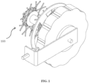
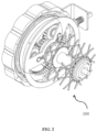
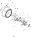
- an epicyclic transmission gear and disk brake based regenerative braking device (100) adapted for pedal assisted geared vehicle with regenerative braking and energy storage features is shown.
- the epicyclic transmission gear and disk brake based regenerative braking device (100) is configured to be positioned on a conventional hub of a rear wheel of a vehicle.
- the device (100) is shown mounted on a rear wheel of a geared vehicle.
- the device (100) may be mounted on rear hub of any other pedal/geared vehicle in other alternative embodiments of the present invention.
- the epicyclic transmission gear and disk brake based regenerative braking device (100) includes a conventional hub (4A).
- the conventional hub has a central opening that receives a shaft (1).
- the conventional hub (4A) is held in position on the shaft by using an opposed pair of retaining rings.
- the conventional hub (4A) includes a pair of circular collars that has a plurality of holes defined thereon. The circular collars engage with a plurality of spokes of a rear wheel of the vehicle.
- the conventional hub (4A) receives a main freewheel (3) along one side thereof.
- the conventional hub (4A) connects to an extended hub (4) through a plurality of connectors (24).
- the extended hub (4) is a sleeve that extends the rear hub (4A) on the far side of the vehicle from chain assembly being mounted on the main freewheel (3).
- the extended hub (4) is secured to the conventional hub (4A) to form an extension such that the extension surface is suitably machined to accommodate various components thereon.
- the extended hub (4) receives a brake disc (5) on outer surface thereof.
- the brake disc (5) is connected to a disc brake clamp unit (6).
- the disk brake unit (6) is configured to stop the rotation of the brake disc (5) by arresting the spin of the disc.
- the brake disk (5) of the disk brake unit is connected to the planetary gear band carrier (8) of the epicyclic transmission unit.
- the disc brake clamp unit (6) connects to a brake cable (not shown) that further connects to a rear wheel friction brake lever/ hand brake lever (not shown).
- the brake lever has an actuated position such that when the disk brake is operated, by squeezing the handle mounted lever, the vehicle de accelerates and eventually stops if the brake lever is squeezed long enough.
- a first needle bush bearing (7) is positioned on the outer surface of the extended hub (4) adjacent to the disc brake carrier (5).
- the epicyclic transmission unit that includes a planet gear band/ carrier plate (8).
- the planet gear band (8) positions on the first needle bush bearing (7).
- the planet gear band (8) has at least there arms (8A) that respectively receive a planet gear shaft (9) through respective openings (8B) thereof.
- Each planet gear shaft (9) is positioned with a planetary gear (12) thereby having a second needle bush bearing (11) positioned therebetween.
- a sun gear (10) is positioned on the extension hub (4).
- the sun gear (10) is configured to mesh with the planetary gears (12) such that the planetary gears (12) spin around their respective axis or around the sun gear (10) due to rotation facilitated by the planet gear band carrier (8).
- the sun gear (10) transfers momentum of the extended hub (4) to a ring gear (13) through the spinning action of the planetary gears (12).
- the ring gear (13) is connected to a clock spring torque storage module.
- the clock spring torque storage module includes an inner casing ring band (14), a one way clutch bearing (15), an inner casing (16), a booster/ clock spring (17) and outer casing (18).
- the inner casing ring band (14) is positioned adjacent to the ring gear (13).
- the one way clutch bearing (15) is positioned adjacent to the epicyclic transmission unit on the extended hub (4) and receives inner casing (16) thereon.
- the outer casing (18) is mounted on the extended hub (4) concentrically with the inner casing (16).
- the inner casing (16), the booster spring (17) and the outer casing (18) form a spring cassette of the present invention.
- the booster spring (17) has a first end that connects to the outer casing (18).
- the booster spring (17) has a second end that connects to the inner casing (16).
- the first and second ends of the booster spring (17) are secured by means of slit openings in the surface of the inner casing (16) and outer casing (18).
- the booster spring (17) is positioned between the outer casing (18) and the inner casing (16) such that the clock spring (17) wraps during rotation of the inner casing (16) in a direction opposite to rotation of rear wheel (2).
- the outer casing (18) has a sinusoidal contoured edge designed to be arrested from spinning for a predetermined torque threshold.
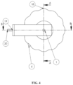
- the device (100) includes a strip chassis unit (19) that has a first end and a second end such that the first end is bolted on the shaft (1) of the hub (4A) and the second end that communicates with a calibrated restraint mechanism that includes a calibration wheel (22) loaded with a calibration screw and a spring (21).
- the calibration wheel (22) is configured to engage with a sinusoidal contoured surface of the outer casing (18) to arrest the outer casing (18) from spinning at a predetermined level of torque.
- the calibration wheel (22) is configured to sit and ride over the sinusoidal peak of the outer casing (18) under a calibrated pressure to enable the outer casing (18) to rotate, when a torque on the spring (17) is in excess of the predetermined torque, thereby facilitating spinning of the outer casing (18).
- the device (100) includes a first circlip (25), a second circlip (26) and a third circlip (27).
- the first circlip (25) assists in securing the epicyclic transmission unit on the extended hub (4).
- the second circlip (26) assists in securing the planet gear shaft (9) on the planet gear band (8).
- the third circlip (27) assists in securing the planet gears (12) on the needle bush bearing (11).
- the one way clutch bearing (15) binds the inner casing (16) to the extended hub (4) when rotating in the same direction of rotation of the wheel (2) when the inner casing is faster than the hub and allows free movement when rotating slower than the spin of the wheel (2) in the forward direction.
- the one way clutch bearing (15) also allows the inner casing (16) to charge when rotating opposite to the rotation of the wheel (2) without impeding the forward motion of the wheel (2).
- the one way clutch bearing (15) allows the inner casing (16) to turn backward for charging/ coiling the booster spring (17) such that this reverse rotation is passed on to it through the ring gear (13).
- the bias of the spring (17) works against the rotation of the extended hub (4) through the ring gear (13), sun gear (10) and planetary gears (12) of the epicyclic transmission unit. This allows the vehicle to de-accelerate on application of the disc brake. It is understood here that the charging action occurs when the planet gear band connected to the disk brake is arrested.
- the disk brake is configured to arrest the spin of the disk (5) in order to stop the rotation of the planetary gear band carrier (8) thereby making the ring gear (13) to rotate in a reverse direction of the sun gear (10).
- the sun gear (10) always rotates in forward direction when the vehicle is in motion.
- the planetary gears (12) mesh with the stationery ring gear (13) and present a stationary surface in contact with the ring gear (13).
- the sun gear (10) to rotate the planet gears (12) rotate around the axis of the sun gear (10). This causes the band or the carrier plate (8) to rotate while the sun gear (10) rotates in the forward rotation of the wheel (2).
- the epicyclic transmission gear and disk brake based regenerative braking device (100) facilitates epicyclic transmission unit to transfer braking energy through arrangement of sun gear (10) and the planetary gears (12) to a clock spring (17) of the clock spring torque storage module in reverse rotation of the spring (17).
- a disk brake is used to arrest the rotation of a sun-planetary gear assembly wherein the planet gear carrier/ band (8) causes the sun gear (10) to be connected to the extended hub (4) to transfer the momentum available at the extended hub (4) to a ring gear (13) in reverse rotation direction to rotation of the rear wheel (2).
- the ring gear (13) connected to the inner casing (16) of the clock spring torque storage module charges the spring (17) by winding it in the reverse direction of the spin of the extended hub (4).
- excess energy after the spring (17) is fully wrapped, is dissipated through spinning of the outer casing (18) of the clock spring torque storage module that is constrained from rotation by a spring calibrated restraint wheel (22) that rides the sinusoidal surface of the outer casing (18).
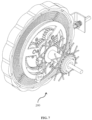
- an alternative embodiment of the epicyclic transmission gear and disk brake based regenerative braking device (100) wherein regenerating functionality is achieved by positioning the clock spring torque storage module and the epicyclic transmission unit concentrically.
- the epicyclic transmission gear and disk brake based regenerative braking device (100) is shown mounted on a bicycle hub.
- the spring based regenerative braking system may be mounted on any other vehicle in further alternative embodiments of the present invention.
- the inner casing (16) of the clock spring torque storage module is concentrically mounted over a circumference of the ring gear (13).
- the inner casing ring band connector (14) is suitably increased in diameter and mounted with an integrated one way clutch (201) over the sun gear (10) of the epicyclic transmission unit. It is understood here that the inner casing ring band 20 connector (14) is affixed to the inner casing (16) in this embodiment.
- the sinusoidal surface of the outer casing (18) is arrested by mating with the spring calibrated restraint wheel (22) of the strip chassis unit (19).
- the epicyclic transmission gear and disk brake based regenerative braking device (100) is thinner in size and larger in diameter than the preferred embodiment of the present invention.
- This alternative embodiment of the epicyclic transmission gear and disk brake based regenerative braking device (100) is preferred when mounted over the conventional hub (4A) as it requires lesser space between the hub (4A) and a rear fork of the vehicle.
Landscapes
- Engineering & Computer Science (AREA)
- Mechanical Engineering (AREA)
- General Engineering & Computer Science (AREA)
- Chemical & Material Sciences (AREA)
- Combustion & Propulsion (AREA)
- Transportation (AREA)
- Retarders (AREA)
Claims (12)
- Dispositif de freinage régénératif à base de transmission par train épicycloïdal et de frein à disque (100) avec des caractéristiques de freinage régénératif et de stockage d'énergie, ledit dispositif de freinage régénératif à base de train épicycloïdal (100) comprenant :un moyeu étendu (4) pouvant être relié à un moyeu classique (4A) d'une roue arrière (2) du véhicule par l'intermédiaire d'une pluralité d'éléments de liaison (24), caractérisé en ce que le moyeu étendu (4) a un premier palier à douille à aiguilles (7) positionné sur une surface extérieure de celui-ci ;une unité serre-frein à disque (6) ayant un disque de frein (5), le disque de frein (5) étant coaxialement monté sur le moyeu étendu (4), l'unité serre-frein à disque (6) étant configurée pour arrêter la rotation du disque de frein (5), l'unité serre-frein à disque (6) se reliant à un levier de frein à main d'un frein à main ;une unité de transmission épicycloïdale ayant une groupe engrenage satellite (8), un engrenage planétaire (10), un engrenage couronne (13) et une pluralité de pièces d'engrenage satellite (12), le groupe engrenage satellite (8) étant positionné sur le palier à douille à aiguilles (7), le groupe engrenage satellite (8) ayant une pluralité de bras (8A) qui reçoivent un arbre d'engrenage satellite (9) à travers des ouvertures respectives (8B) de ceux-ci, chaque arbre d'engrenage satellite (9) ayant un second palier à douille à aiguilles (11) positionné sur celui-ci, chaque second palier à douille à aiguilles (11) recevant respectivement la pièce d'engrenage satellite (12) sur celui-ci, l'engrenage planétaire (10) se positionnant sur le moyeu étendu (4), l'engrenage planétaire (10) s'engrenant avec la pluralité de pièces d'engrenage satellite (12), l'engrenage couronne (13) étant configuré pour recevoir une quantité de mouvement par l'intermédiaire des pièces d'engrenage satellite (12) dans une direction inverse à la rotation de l'engrenage planétaire (10) à la suite d'un mouvement arrêté du groupe engrenage satellite (8), le groupe engrenage satellite (8) se reliant au disque de frein (5) de l'unité de frein à disque (6) pour transférer une quantité de mouvement à l'engrenage couronne (13) ;un module de stockage de couple à ressort d'horloge ayant une groupe annulaire de carter intérieur (14), un palier d'embrayage unidirectionnel (15), un carter intérieur (16), un ressort amplificateur/d'horloge (17) et un carter extérieur (18), le palier d'embrayage unidirectionnel (15) étant positionné sur le moyeu étendu (4), le palier d'embrayage unidirectionnel (15) recevant le carter intérieur (16) sur celui-ci, le carter intérieur (16) étant configuré pour recevoir un transfert de quantité de mouvement à partir de l'engrenage couronne (13), le carter extérieur (18) ayant une surface profilée sinusoïdale, le ressort d'horloge (17) étant configuré pour être enroulé durant la rotation du carter intérieur (16) dans une direction opposée à la rotation de roue arrière (2) ; etune unité de châssis en bande (19) boulonnée sur un arbre (1) du moyeu classique (4A), l'unité de châssis en bande (19) ayant une roue de limitation étalonnée à ressort (22) chargée avec une vis d'étalonnage (20) et un ressort (21), la roue de limitation étalonnée à ressort (22) étant configurée pour entrer en prise avec la surface profilée sinusoïdale du carter extérieur (18) pour arrêter la révolution du carter extérieur (18), à un couple inférieur à un couple prédéterminé.
- Dispositif de freinage régénératif à base de transmission par train épicycloïdal et de frein à disque (100) selon la revendication 1, dans lequel le carter intérieur (16) et le carter extérieur (18) ont respectivement une fente interne pour monter une extrémité respective du ressort d'horloge (17).
- Dispositif de freinage régénératif à base de transmission par train épicycloïdal et de frein à disque (100) selon la revendication 1, dans lequel le roue de limitation étalonnée à ressort (22) est configurée pour se placer et passer par-dessus la crête sinusoïdale du carter extérieur (18) sous une pression étalonnée pour permettre au carter extérieur (18) d'entrer en rotation lorsqu'un couple sur le ressort (17) dépasse le couple prédéterminé.
- Dispositif de freinage régénératif à base de transmission par train épicycloïdal et de frein à disque (100) selon la revendication 1, dans lequel l'unité de transmission épicycloïdale est fixée sur le moyeu étendu avec un premier anneau de retenue (25).
- Dispositif de freinage régénératif à base de transmission par train épicycloïdal et de frein à disque (100) selon la revendication 1, dans lequel l'arbre d'engrenage satellite (9) est fixé sur le groupe engrenage satellite (8) avec un deuxième anneau de retenue (26).
- Dispositif de freinage régénératif à base de transmission par train épicycloïdal et de frein à disque (100) selon la revendication 1, dans lequel chaque pièce d'engrenage satellite (12) est fixée sur un palier à douille à aiguilles respectif (11) avec un troisième anneau de retenue (27).
- Dispositif de freinage régénératif à base de transmission par train épicycloïdal et de frein à disque (100) selon la revendication 1, dans lequel le palier d'embrayage unidirectionnel (15) lie le carter intérieur (16) au moyeu étendu (4) durant la rotation dans la même direction que la rotation de la roue (2) seulement lorsque la rotation du palier d'embrayage unidirectionnel (15) est plus rapide que la rotation de la roue (2) mais supprime l'influence du moyeu étendu (4) lorsque la rotation du palier d'embrayage unidirectionnel (15) est plus lente que la rotation du moyeu (4) ou le palier d'embrayage unidirectionnel (15) entre en rotation dans une direction inverse à la rotation de la roue (2).
- Dispositif de freinage régénératif à base de transmission par train épicycloïdal et de frein à disque (100) selon la revendication 1, dans lequel le palier d'embrayage unidirectionnel (15) permet un mouvement libre lors d'une rotation plus lente que la révolution de la roue (2) dans la direction en avant.
- Dispositif de freinage régénératif à base de transmission par train épicycloïdal et de frein à disque (100) selon la revendication 1, dans lequel le carter intérieur (16) alimente le moyeu étendu (4) lorsque le ressort amplificateur (17) se décharge plus rapidement que la rotation en avant du moyeu étendu (4).
- Dispositif de freinage régénératif à base de transmission par train épicycloïdal et de frein à disque (100) selon la revendication 1, dans lequel, le palier d'embrayage unidirectionnel (15) permet au carter intérieur (16) de tourner vers l'arrière par rapport à la rotation de la roue (2) pour charger/enrouler le ressort amplificateur (17) de telle sorte qu'une rotation inverse soit transmise à celui-ci par l'intermédiaire de l'engrenage couronne (13).
- Dispositif de freinage régénératif à base de transmission par train épicycloïdal et de frein à disque (100) selon la revendication 10, dans lequel une sollicitation du ressort (17) agit contre la rotation du moyeu étendu (4) mutuellement par l'intermédiaire de l'engrenage couronne (13), de l'engrenage planétaire (10) et des pièces d'engrenage satellite (12) pour ralentir le véhicule lors de l'application du frein à disque.
- Dispositif de freinage régénératif à base de transmission par train épicycloïdal et de frein à disque (100) selon la revendication 1, dans lequel l'unité de frein à disque (6) arrête la révolution du disque de frein (5) de telle sorte que la rotation du porte-groupe engrenage satellite (8) soit interrompue, ce qui fait en sorte que l'engrenage couronne (13) entre en rotation dans une direction inverse par rapport à l'engrenage planétaire (10).
Applications Claiming Priority (2)
| Application Number | Priority Date | Filing Date | Title |
|---|---|---|---|
| PCT/IN2018/050672 WO2020044354A1 (fr) | 2018-08-31 | 2018-10-17 | Dispositif de freinage régénératif basé sur un engrenage de transmission épicycloïdal et un frein à disque |
| IN201821032750A IN201821032750A (fr) | 2018-08-31 | 2018-10-17 |
Publications (4)
| Publication Number | Publication Date |
|---|---|
| EP3844038A1 EP3844038A1 (fr) | 2021-07-07 |
| EP3844038A4 EP3844038A4 (fr) | 2022-03-30 |
| EP3844038C0 EP3844038C0 (fr) | 2023-08-09 |
| EP3844038B1 true EP3844038B1 (fr) | 2023-08-09 |
Family
ID=69644031
Family Applications (1)
| Application Number | Title | Priority Date | Filing Date |
|---|---|---|---|
| EP18931698.7A Active EP3844038B1 (fr) | 2018-08-31 | 2018-10-17 | Dispositif de freinage régénératif basé sur un engrenage de transmission épicycloïdal et un frein à disque |
Country Status (4)
| Country | Link |
|---|---|
| US (1) | US11852206B2 (fr) |
| EP (1) | EP3844038B1 (fr) |
| IN (1) | IN201821032750A (fr) |
| WO (1) | WO2020044354A1 (fr) |
Families Citing this family (3)
| Publication number | Priority date | Publication date | Assignee | Title |
|---|---|---|---|---|
| US20230399075A1 (en) * | 2020-10-15 | 2023-12-14 | Ravi Ganesh Athalye | A mechanical regenerative braking system |
| CN119636948B (zh) * | 2024-12-05 | 2025-12-02 | 哈尔滨工业大学 | 一种用于四足机器人坠落姿态调整的旋转飞轮动量调节器 |
| CN120102135B (zh) * | 2025-05-08 | 2025-07-04 | 绵阳师范学院 | 风力发电机组联轴器打滑故障检测装置 |
Family Cites Families (10)
| Publication number | Priority date | Publication date | Assignee | Title |
|---|---|---|---|---|
| US4744577A (en) * | 1986-04-21 | 1988-05-17 | Brent Mark R | Regenerative braking system for bicycles |
| US4827798A (en) * | 1987-06-04 | 1989-05-09 | Anchor Tech., Inc. | Apparatus and method for exerting a braking torque upon a vehicle |
| US6053830A (en) * | 1997-08-20 | 2000-04-25 | Glaeser; Robert C. | Power-spring assist to pedals of bicycle |
| US6019385A (en) * | 1997-11-26 | 2000-02-01 | Kelley; Don | Energy storage device for personal vehicle |
| US8251166B2 (en) * | 2009-04-27 | 2012-08-28 | GM Global Technology Operations LLC | Hybrid powertrain with assisted starting and method of starting an engine |
| US8622859B2 (en) * | 2009-06-10 | 2014-01-07 | Czero Holding Company, Llc | Systems and methods for hybridization of a motor vehicle using hydraulic components |
| SE536049C2 (sv) * | 2011-06-27 | 2013-04-16 | Scania Cv Ab | Regenerativ bromsanordning för ett fordon och förfarande för regenerativ bromsning av ett fordon |
| US9441599B2 (en) * | 2012-07-17 | 2016-09-13 | Altigreen Propulsion Labs Private Limited | Induction motor-permanent magnet generator tandem configuration starter-generator for hybrid vehicles |
| SG11201807092UA (en) * | 2016-02-22 | 2018-09-27 | Ravi G Athalye | Spring based regenerative braking system |
| CN106402205B (zh) * | 2016-10-28 | 2018-11-09 | 江苏理工学院 | 汽车电子机械制动系统轮边自供电式制动执行机构 |
-
2018
- 2018-10-17 IN IN201821032750A patent/IN201821032750A/en unknown
- 2018-10-17 WO PCT/IN2018/050672 patent/WO2020044354A1/fr not_active Ceased
- 2018-10-17 EP EP18931698.7A patent/EP3844038B1/fr active Active
- 2018-10-17 US US17/270,892 patent/US11852206B2/en active Active
Also Published As
| Publication number | Publication date |
|---|---|
| EP3844038A4 (fr) | 2022-03-30 |
| IN201821032750A (fr) | 2020-03-06 |
| EP3844038A1 (fr) | 2021-07-07 |
| EP3844038C0 (fr) | 2023-08-09 |
| WO2020044354A1 (fr) | 2020-03-05 |
| US11852206B2 (en) | 2023-12-26 |
| US20210180657A1 (en) | 2021-06-17 |
Similar Documents
| Publication | Publication Date | Title |
|---|---|---|
| EP3844038B1 (fr) | Dispositif de freinage régénératif basé sur un engrenage de transmission épicycloïdal et un frein à disque | |
| US9994284B2 (en) | Bicycle assist unit | |
| US6478711B2 (en) | Apparatus for changing speed of bicycles | |
| US20190047525A1 (en) | Spring based regenerative braking system | |
| TW318815B (fr) | ||
| US4744577A (en) | Regenerative braking system for bicycles | |
| EP2586694A1 (fr) | Bicyclette à assistance électrique | |
| US4461375A (en) | One-way transmission system for bicycles or the like | |
| WO2003080981A9 (fr) | Embrayage de store a enroulement automatique, dote d'un engrenage interne | |
| US11052961B2 (en) | Selectable motor clutch, system, and method | |
| EP0425526A1 (fr) | Moyeu de changement automatique de vitesses sensible au couple | |
| US5027930A (en) | Coaster brake assembly | |
| US20230399075A1 (en) | A mechanical regenerative braking system | |
| US3432015A (en) | Reversible one-way clutch with pilot brake | |
| CN113677589B (zh) | 扭矩晶体管和带有扭矩晶体管的电动自行车 | |
| US10604213B2 (en) | Bicycle transmission for use between a chain wheel carrier and a wheel hub of a bicycle, as well as rear axle and rear wheel provided with such a transmission | |
| JP2003146285A (ja) | 動力伝達機構及び動力伝達機構を備えた自転車 | |
| US6358285B1 (en) | Motor-driven prosthetic prehensor | |
| WO2019035137A1 (fr) | Système pour bicyclette à engrenages avec freinage régénératif et stockage d'énergie par pédalage en sens inverse | |
| US3203519A (en) | Freewheeling hub with coaster brake | |
| US20230066122A1 (en) | Driving mechanism of bicycle free-coaster hub | |
| US3270589A (en) | Dual speed hub with automatic speed shift | |
| US5810139A (en) | Bicycle and a friction device for controlling a clamping roller coupling of a bicycle hub of a bicycle | |
| US2982384A (en) | Semi-automatic two-speed hub and coaster brake | |
| CN217673008U (zh) | 个人车辆 |
Legal Events
| Date | Code | Title | Description |
|---|---|---|---|
| STAA | Information on the status of an ep patent application or granted ep patent |
Free format text: STATUS: THE INTERNATIONAL PUBLICATION HAS BEEN MADE |
|
| STAA | Information on the status of an ep patent application or granted ep patent |
Free format text: STATUS: REQUEST FOR EXAMINATION WAS MADE |
|
| PUAI | Public reference made under article 153(3) epc to a published international application that has entered the european phase |
Free format text: ORIGINAL CODE: 0009012 |
|
| 17P | Request for examination filed |
Effective date: 20210225 |
|
| AK | Designated contracting states |
Kind code of ref document: A1 Designated state(s): AL AT BE BG CH CY CZ DE DK EE ES FI FR GB GR HR HU IE IS IT LI LT LU LV MC MK MT NL NO PL PT RO RS SE SI SK SM TR |
|
| DAV | Request for validation of the european patent (deleted) | ||
| DAX | Request for extension of the european patent (deleted) | ||
| A4 | Supplementary search report drawn up and despatched |
Effective date: 20220228 |
|
| RIC1 | Information provided on ipc code assigned before grant |
Ipc: B60L 7/00 20060101ALI20220222BHEP Ipc: B60T 1/10 20060101AFI20220222BHEP |
|
| GRAP | Despatch of communication of intention to grant a patent |
Free format text: ORIGINAL CODE: EPIDOSNIGR1 |
|
| STAA | Information on the status of an ep patent application or granted ep patent |
Free format text: STATUS: GRANT OF PATENT IS INTENDED |
|
| INTG | Intention to grant announced |
Effective date: 20230317 |
|
| GRAS | Grant fee paid |
Free format text: ORIGINAL CODE: EPIDOSNIGR3 |
|
| GRAA | (expected) grant |
Free format text: ORIGINAL CODE: 0009210 |
|
| STAA | Information on the status of an ep patent application or granted ep patent |
Free format text: STATUS: THE PATENT HAS BEEN GRANTED |
|
| AK | Designated contracting states |
Kind code of ref document: B1 Designated state(s): AL AT BE BG CH CY CZ DE DK EE ES FI FR GB GR HR HU IE IS IT LI LT LU LV MC MK MT NL NO PL PT RO RS SE SI SK SM TR |
|
| REG | Reference to a national code |
Ref country code: GB Ref legal event code: FG4D |
|
| REG | Reference to a national code |
Ref country code: CH Ref legal event code: EP |
|
| REG | Reference to a national code |
Ref country code: DE Ref legal event code: R096 Ref document number: 602018055280 Country of ref document: DE |
|
| REG | Reference to a national code |
Ref country code: IE Ref legal event code: FG4D |
|
| U01 | Request for unitary effect filed |
Effective date: 20230821 |
|
| U07 | Unitary effect registered |
Designated state(s): AT BE BG DE DK EE FI FR IT LT LU LV MT NL PT SE SI Effective date: 20230907 |
|
| PG25 | Lapsed in a contracting state [announced via postgrant information from national office to epo] |
Ref country code: GR Free format text: LAPSE BECAUSE OF FAILURE TO SUBMIT A TRANSLATION OF THE DESCRIPTION OR TO PAY THE FEE WITHIN THE PRESCRIBED TIME-LIMIT Effective date: 20231110 |
|
| PG25 | Lapsed in a contracting state [announced via postgrant information from national office to epo] |
Ref country code: IS Free format text: LAPSE BECAUSE OF FAILURE TO SUBMIT A TRANSLATION OF THE DESCRIPTION OR TO PAY THE FEE WITHIN THE PRESCRIBED TIME-LIMIT Effective date: 20231209 |
|
| PG25 | Lapsed in a contracting state [announced via postgrant information from national office to epo] |
Ref country code: RS Free format text: LAPSE BECAUSE OF FAILURE TO SUBMIT A TRANSLATION OF THE DESCRIPTION OR TO PAY THE FEE WITHIN THE PRESCRIBED TIME-LIMIT Effective date: 20230809 Ref country code: NO Free format text: LAPSE BECAUSE OF FAILURE TO SUBMIT A TRANSLATION OF THE DESCRIPTION OR TO PAY THE FEE WITHIN THE PRESCRIBED TIME-LIMIT Effective date: 20231109 Ref country code: IS Free format text: LAPSE BECAUSE OF FAILURE TO SUBMIT A TRANSLATION OF THE DESCRIPTION OR TO PAY THE FEE WITHIN THE PRESCRIBED TIME-LIMIT Effective date: 20231209 Ref country code: HR Free format text: LAPSE BECAUSE OF FAILURE TO SUBMIT A TRANSLATION OF THE DESCRIPTION OR TO PAY THE FEE WITHIN THE PRESCRIBED TIME-LIMIT Effective date: 20230809 Ref country code: GR Free format text: LAPSE BECAUSE OF FAILURE TO SUBMIT A TRANSLATION OF THE DESCRIPTION OR TO PAY THE FEE WITHIN THE PRESCRIBED TIME-LIMIT Effective date: 20231110 |
|
| PG25 | Lapsed in a contracting state [announced via postgrant information from national office to epo] |
Ref country code: PL Free format text: LAPSE BECAUSE OF FAILURE TO SUBMIT A TRANSLATION OF THE DESCRIPTION OR TO PAY THE FEE WITHIN THE PRESCRIBED TIME-LIMIT Effective date: 20230809 |
|
| PG25 | Lapsed in a contracting state [announced via postgrant information from national office to epo] |
Ref country code: ES Free format text: LAPSE BECAUSE OF FAILURE TO SUBMIT A TRANSLATION OF THE DESCRIPTION OR TO PAY THE FEE WITHIN THE PRESCRIBED TIME-LIMIT Effective date: 20230809 |
|
| PG25 | Lapsed in a contracting state [announced via postgrant information from national office to epo] |
Ref country code: SM Free format text: LAPSE BECAUSE OF FAILURE TO SUBMIT A TRANSLATION OF THE DESCRIPTION OR TO PAY THE FEE WITHIN THE PRESCRIBED TIME-LIMIT Effective date: 20230809 Ref country code: RO Free format text: LAPSE BECAUSE OF FAILURE TO SUBMIT A TRANSLATION OF THE DESCRIPTION OR TO PAY THE FEE WITHIN THE PRESCRIBED TIME-LIMIT Effective date: 20230809 Ref country code: ES Free format text: LAPSE BECAUSE OF FAILURE TO SUBMIT A TRANSLATION OF THE DESCRIPTION OR TO PAY THE FEE WITHIN THE PRESCRIBED TIME-LIMIT Effective date: 20230809 Ref country code: CZ Free format text: LAPSE BECAUSE OF FAILURE TO SUBMIT A TRANSLATION OF THE DESCRIPTION OR TO PAY THE FEE WITHIN THE PRESCRIBED TIME-LIMIT Effective date: 20230809 Ref country code: SK Free format text: LAPSE BECAUSE OF FAILURE TO SUBMIT A TRANSLATION OF THE DESCRIPTION OR TO PAY THE FEE WITHIN THE PRESCRIBED TIME-LIMIT Effective date: 20230809 |
|
| REG | Reference to a national code |
Ref country code: DE Ref legal event code: R097 Ref document number: 602018055280 Country of ref document: DE |
|
| PG25 | Lapsed in a contracting state [announced via postgrant information from national office to epo] |
Ref country code: MC Free format text: LAPSE BECAUSE OF FAILURE TO SUBMIT A TRANSLATION OF THE DESCRIPTION OR TO PAY THE FEE WITHIN THE PRESCRIBED TIME-LIMIT Effective date: 20230809 |
|
| REG | Reference to a national code |
Ref country code: CH Ref legal event code: PL |
|
| U90 | Renewal fees not paid: noting of loss of rights |
Free format text: RENEWAL FEE NOT PAID FOR YEAR 06 Effective date: 20240516 |
|
| PLBE | No opposition filed within time limit |
Free format text: ORIGINAL CODE: 0009261 |
|
| STAA | Information on the status of an ep patent application or granted ep patent |
Free format text: STATUS: NO OPPOSITION FILED WITHIN TIME LIMIT |
|
| 26N | No opposition filed |
Effective date: 20240513 |
|
| PG25 | Lapsed in a contracting state [announced via postgrant information from national office to epo] |
Ref country code: CH Free format text: LAPSE BECAUSE OF NON-PAYMENT OF DUE FEES Effective date: 20231031 |
|
| GBPC | Gb: european patent ceased through non-payment of renewal fee |
Effective date: 20231109 |
|
| PG25 | Lapsed in a contracting state [announced via postgrant information from national office to epo] |
Ref country code: CH Free format text: LAPSE BECAUSE OF NON-PAYMENT OF DUE FEES Effective date: 20231031 |
|
| PG25 | Lapsed in a contracting state [announced via postgrant information from national office to epo] |
Ref country code: IE Free format text: LAPSE BECAUSE OF NON-PAYMENT OF DUE FEES Effective date: 20231017 |
|
| PG25 | Lapsed in a contracting state [announced via postgrant information from national office to epo] |
Ref country code: GB Free format text: LAPSE BECAUSE OF NON-PAYMENT OF DUE FEES Effective date: 20231109 |
|
| U93 | Unitary patent lapsed |
Free format text: RENEWAL FEE NOT PAID Effective date: 20231031 |
|
| PG25 | Lapsed in a contracting state [announced via postgrant information from national office to epo] |
Ref country code: IE Free format text: LAPSE BECAUSE OF NON-PAYMENT OF DUE FEES Effective date: 20231017 Ref country code: GB Free format text: LAPSE BECAUSE OF NON-PAYMENT OF DUE FEES Effective date: 20231109 |
|
| PG25 | Lapsed in a contracting state [announced via postgrant information from national office to epo] |
Ref country code: CY Free format text: LAPSE BECAUSE OF FAILURE TO SUBMIT A TRANSLATION OF THE DESCRIPTION OR TO PAY THE FEE WITHIN THE PRESCRIBED TIME-LIMIT; INVALID AB INITIO Effective date: 20181017 |
|
| PG25 | Lapsed in a contracting state [announced via postgrant information from national office to epo] |
Ref country code: HU Free format text: LAPSE BECAUSE OF FAILURE TO SUBMIT A TRANSLATION OF THE DESCRIPTION OR TO PAY THE FEE WITHIN THE PRESCRIBED TIME-LIMIT; INVALID AB INITIO Effective date: 20181017 |
|
| PG25 | Lapsed in a contracting state [announced via postgrant information from national office to epo] |
Ref country code: TR Free format text: LAPSE BECAUSE OF FAILURE TO SUBMIT A TRANSLATION OF THE DESCRIPTION OR TO PAY THE FEE WITHIN THE PRESCRIBED TIME-LIMIT Effective date: 20230809 |