EP3844087B1 - Transport und heben von schlamm - Google Patents
Transport und heben von schlamm Download PDFInfo
- Publication number
- EP3844087B1 EP3844087B1 EP19853808.4A EP19853808A EP3844087B1 EP 3844087 B1 EP3844087 B1 EP 3844087B1 EP 19853808 A EP19853808 A EP 19853808A EP 3844087 B1 EP3844087 B1 EP 3844087B1
- Authority
- EP
- European Patent Office
- Prior art keywords
- solids
- chamber
- water
- valve
- high pressure
- Prior art date
- Legal status (The legal status is an assumption and is not a legal conclusion. Google has not performed a legal analysis and makes no representation as to the accuracy of the status listed.)
- Active
Links
Images


Classifications
-
- E—FIXED CONSTRUCTIONS
- E21—EARTH OR ROCK DRILLING; MINING
- E21F—SAFETY DEVICES, TRANSPORT, FILLING-UP, RESCUE, VENTILATION, OR DRAINING IN OR OF MINES OR TUNNELS
- E21F13/00—Transport specially adapted to underground conditions
-
- B—PERFORMING OPERATIONS; TRANSPORTING
- B65—CONVEYING; PACKING; STORING; HANDLING THIN OR FILAMENTARY MATERIAL
- B65G—TRANSPORT OR STORAGE DEVICES, e.g. CONVEYORS FOR LOADING OR TIPPING, SHOP CONVEYOR SYSTEMS OR PNEUMATIC TUBE CONVEYORS
- B65G53/00—Conveying materials in bulk through troughs, pipes or tubes by floating the materials or by flow of gas, liquid or foam
- B65G53/30—Conveying materials in bulk through pipes or tubes by liquid pressure
-
- E—FIXED CONSTRUCTIONS
- E21—EARTH OR ROCK DRILLING; MINING
- E21F—SAFETY DEVICES, TRANSPORT, FILLING-UP, RESCUE, VENTILATION, OR DRAINING IN OR OF MINES OR TUNNELS
- E21F13/00—Transport specially adapted to underground conditions
- E21F13/04—Transport of mined material in gravity inclines; in staple or inclined shafts
- E21F13/042—Vertical hydraulic conveying of coal
Definitions
- the invention relates to equipment for, a system for, and a method of introducing ore, crushed rock, run-of-mine and/or other particulate material ("solids") into a delivery conduit for transport as a slurry and particularly for hoisting in a column.
- the invention will be implemented in the depths of a mine and employ a U-tube configuration with water travelling down a supply column into lower levels (usually of an underground mine) where the "solids" are collected and up another, delivery column.
- Prior patent number US 4 699 548 (1987 ) relates to systems for fluidizing particulate materials and conveying same while in liquid suspension.
- the slurry conveying system includes a pressure vessel into which particulate is charged through a top inlet. Fluidizing water is injected upwardly from a bottom of the vessel at a relatively high velocity to precondition the solids and prevent blockages. Rinsing water and pressurised air as a conveying medium are then introduced.
- Prior patent US 9 133 701 discloses an apparatus and method for introducing an oilfield material, such as a proppant, on the high-pressure side of a hydraulic well stimulation system.
- Proppants and any additives are introduced into one or more pressure vessels at low pressure.
- the pressure vessel inlets used to add the proppants are then closed.
- High-pressure fluid from a pump is used to pressurize the pressure vessel and introduce the oilfield material to the high-pressure line.
- a 3CPS may be fed underground by a slurry fluidiser.
- the fluidisation serves to achieve the slurry as required and this must then be introduced between water of the incoming and outgoing columns.
- the "fluidiser” is required to provide slurry at a nominal concentration.
- valves need to be closed in the presence of solids and/or fines.
- feeder arrangement for a slurry transport system comprising at least one chamber with a top end and a bottom end, the chamber including:
- the invention further provides for a feeder arrangement as defined, in which:
- the flow at an outlet of the by-pass duct serves to dislodge and mobilise solids inside the pile adjacent the high pressure solids and water outlet.
- the invention further provides for a feeder arrangement as defined, in which:
- a flow-resistance device to be provided above the lower section of the chamber; for there to be two or more flow resistance devices at spaced apart positions along the chamber; and for the flow-resistance devices to be provided as orifice (or perforated) plates, alternatively, as a stack of parallel tubes or of any other suitable construction that prevents mixing or deters migration of fines from the lower section to the upper section.
- the invention further provides for a feeder arrangement as defined, in which the low pressure water outlet is connected to a constant-head arrangement with a water level that keeps the second valve submerged.
- a further feature of the invention provides for the constant-head arrangement to a constant-head tank with an over-flow weir positioned above the second valve.
- the invention further provides for a feeder arrangement as defined, in which: a primary connection is provided into the top end of the chamber, above which the second valve is located and through which the transfer chute extends into the chamber, a secondary connection is provided that extends into a side of the primary connection, with the high pressure water inlet and the low pressure water outlet connected to the secondary connection for communication with the chamber through the primary connection, around the transfer chute.
- the invention accordingly provides for the high pressure water inlet and the low pressure water outlet to be in communication with the chamber through the primary connection around the transfer chute.
- the invention further provides for a feeder arrangement as defined, in which:
- a further feature of the invention provides for the constant-head tank to be connected through a second lower tank and return pump to a third upper tank which feeds the least one injection pump.
- the invention provides for the re-injection of displaced water into the slurry transport system to achieve dilution and favourable solids/rock densities. Where the re-injected water goes back into clear-water supply conduit, it contributes to clearing the chamber as well as dilution of the solids.
- the invention further provides for a feeder arrangement as defined which includes two or more chambers that are vertically supported and arranged parallel in an adjacent configuration, each with a high pressure solids and water outlet feeding separately into a manifold that is connected to the delivery conduit.
- the invention further provides for a feeder arrangement as defined, in which:
- a further feature of the invention provides for the return line of the at least one injection pump to be connected into the manifold.
- the invention further provides for a feeder arrangement as defined, in which:
- a further feature of the invention provides for a delivery conduit flush valve to be provided in a branch that connects the supply conduit to the return line downstream from the at least one injection pump to by-pass the feeder arrangement.
- the invention further provides for a method as defined, in which:
- Further features of the invention provide for the solids to be directed from the solids inlet valve to the lower section of the chamber directly via the transfer chute and using a gravity head (fall height) from the solids filling flask; for the solids to be concentrated at the bottom of the chamber (i.e. not uniformly mixing them throughout the chamber) via the transfer chute and for a clear-water environment to be maintained in an upper section of the chamber; and for the bottom by-pass duct to be used to connect an upper section of the chamber to a lower section of the chamber (which is filled with solids) for the solids to be fluidised and diluted on exiting of the chamber.
- a gravity head fall height
- Further features of the invention provide for water displaced by the solids to be reintroduced into the slurry transport system using at least one high pressure injection pump; for the high pressure injection pump to be connected into a slurry delivery conduit and/or a clear-water supply conduit to the high pressure inlet.
- the invention provides for a first valve to be opened for inlet of high pressure water, a second valve to be opened for inlet of solids, a third valve to be opened for outlet of low pressure water displaced by the solids, and a fourth valve at a bottom of the chamber to be opened for outlet of high pressure water and solids.
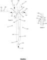
- apparatus in accordance with the invention provides a drop chamber hydro hoist which will generally be referred to as a 3 chamber hydro hoist or 3CHH (100).
- the 3CHH (100) is provided to vertically lift solids or ore in a slurry form.
- the complete hydro hoist provides a slurry transport system (100) and can be separated into two sections for this description: the 3CHH core or feeder arrangement (102); and the adjacent systems (which will be separately numbered where relevant).
- the adjacent systems include the incoming, supply (104) and outgoing, delivery (106) vertical pipe columns, solids batching equipment, connecting pipes, valves, tanks, pumps, surface equipment and all the components of the system not in the 3CHH core (102).
- the drawings do not show the adjacent systems in any detail.
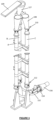
- the 3CHH core (102) includes three chambers (A, B, C) that are vertically arranged below respective batching flasks (108).
- the 3CHH core (102) provides a feeder arrangement for the slurry transport or hoisting system (100), wherein each chamber has a top end (110) and a bottom end (112) and includes:
- the low pressure solids inlet (118) has a transfer chute (130) that opens into a lower section (132) of the chamber (A, B, C) to maintain a clear-water environment adjacent the top end (110).
- the three chambers (A, B, C) are supported in a raise-bore hole of suitable diameter (about 3.5 m in this example) provided between two levels in an underground working of a mine.
- the 3CHH core (102) is located between a first, upper level and a second, lower level.
- the levels may be about 1600m below surface with about a 40 m vertical separation between the two levels.
- the 3CHH (100) is connected to the clear-water supply column (104) from surface and delivers slurry up the delivery column (106) to the surface.
- a 250NB column size is proposed for the columns in this example.
- a minimum of two columns (104) and (106) are required for clear-water supply from the surface to the 3CHH core (102) underground and for slurry delivery from underground to surface.
- the pipeline columns between the clear-water and slurry delivery level and the surface are made substantially identical with the purpose of being interchangeable so that the function can be periodically rotated enabling the wear caused by the vertical upwards flow of slurry to be shared between the columns.
- the invention further provides for a spare column or columns to be included and for the functions of the columns to be periodically changed, so the wear can be shared between all the columns, thus extending the life of the hydro hoist and reducing risk in the event of a column failure (for whatever reason).
- the interchangeability will depend on a scheduled shutdown, disconnection from a column that has been drained and reconnection to the extra column.
- a surface booster pump (134) pushes the water down the clear-water supply column, through the three chambers (A, B and C) and up the slurry delivery column.
- the booster pump duty is well suited to a multi-stage, centrifugal-pump with variable-speed drive (VSD) control.
- an underground, clear-water injection pump (136) or pumps are used to inject the water displaced by solids (and due to compression, air and other flushing or other water added) back into the slurry transport system.
- the displaced water re-injected into a delivery line (138), downstream from the 3CHH core (102).
- the 3CHH (100) can be constructed to operate on only two active columns because displaced clear-water is injected back into the slurry delivery column by the injection pumps.
- the re-injection of displaced water into the slurry transport system serves to achieve dilution and favourable solids/rock densities.
- the displaced water may also be re-injected back into a clear-water supply conduit (139) upstream of the chamber or into the chamber (A, B, C) directly. In that case, the re-injected water contributes to clearing the chamber as well as dilution of the solids.
- the pumps (134) and (136) provide energy to overcome frictional pressure drops and the frictional energy dissipation by the solids hindered settling velocity and to lift the solids against the force of gravity.
- the three chambers (A, B, C) are vertically supported and arranged parallel in a triangular configuration.
- the three chambers are gravity-filled from the batching flasks (108) located above each.
- the batching flasks may be fed with solids from a belt conveyor (109) on the upper level.
- the feed (crushed rock) from the conveyor will preferably include addition of clear- or dirty-water which is sprayed into the solids in the flask.
- the solids are wet fed into the three flasks, each of which has a weir (111) and overflow collection bin.
- a rotating eccentric or bent pipe is used to fill the batching flasks (108) with the wet-solids. In this manner, each batching flask is filled to a substantially fixed volume to provide a consistent batch for each chamber. The overflow will be recirculated.
- the transfer chute (130) that extends from the solids inlet (118) delivers "falling" solids, from a second, solids inlet valve at the top (110) of the chamber, to the lower section (132) of the chamber and allowing for quick delivery to the bottom (112) of the chamber (A, B, C).
- a bottom by-pass duct (140) is configured and arranged to deliver water from above the lower section (132) of the chamber to adjacent a bottom of the solids bed in the lower section.
- the chambers can be suitably inclined instead of vertical.
- a vertical (or inclined) chamber arrangement uses gravity to assist the flow of solids into and out of the chambers.
- the chamber bottom (112) is also tapered or inclined towards the high pressure solids and water outlet (126) to facilitate evacuation of the solids from the chamber (A, B, C).
- Distribution into the three chambers (A, B, C) is achieved by means of an eccentric rotary distributor or funnel (127) that fills each flask in sequence.
- the rotary distributor (127) rotates one revolution for one complete cycle (i.e. 3 individual chamber cycles).
- the position of the distributor is measured with a rotary encoder which ensures suitable synchronization.
- the rotary distributor gearbox motor is speed controlled to ensure synchronization with the cycle.
- a top second, solids inlet valve (120) is used to control the introduction of solids that are "dropped" into the vertical chamber (A, B, C) from the flask in a fraction of the single chamber cycle time (e.g. about 33% to 66% of the total time). This leaves the remainder of the time to flush the flask (108) and second, solids inlet valve (120).
- flushing water sprays that can be introduced in a manner that serves to agitate the rock in the flask (108) to aid the emptying of the flask and to clear all the rock from the flask through the second, solids inlet valve (120).
- Water sprays (preferably two or more) will also be located adjacent and suitably directed into the second, solids inlet valve (120) to keep it clear of solids. Importantly, this also allows the second, solids inlet valve (120) to be reliably closed in clear-water and to therefore seal effectively with minimal wear.
- the sprays will be connected to a water supply (142) from a clear water flush tank.
- the transfer chute (130) allows the solids to gravitate from the second, solids inlet valve (120) to the bottom (112) of the vertical chamber (A, B, C), forming a slightly stratified bed at the bottom of the chamber. When the solids fall through the water in the lower section there will be some mixing of the water as this is displaced upwards.
- the transfer chute (130) ends or opens at a height above the bottom of the vertical chamber so that solids are separated from a top zone/volume at an upper section (144) of the chamber.
- a volume of clear-water equal to the volume of water and solids added to the chamber will be displaced through the third, low pressure water outlet valve (124). This will be clear-water coming from the upper section or volume (144) of the vertical chamber (A, B, C).
- the arrangement and position of the third valve (124) ensures that it can be reliably closed in clear-water and seal effectively with minimal wear.
- a clear-water constant-head tank (146) collects the displaced clear-water that flows through the open the third, low pressure water outlet valve (124).
- the level of a notched over-flow weir (148) is positioned just above the top of the second, solids inlet valve (120) to avoid an air pocket in the top of the chamber just below the second, solids inlet valve (120).
- the clear-water constant-head tank (146) is in turn connected through a lower (clear-water) tank and return pump and an upper (clear-water) tank to the injection pumps (136).
- the over-flow from the constant-head weir (148) will gravitate to the lower, clear-water tank, where it is later pumped to the upper-level clear-water tank.
- This upper tank will be positioned at an elevation such that it can provide a flooded suction for the injection pump (136).
- the by-pass duct (140) provides a quick route or low resistance path to bottom valve to dilute the coarse solids.
- the water through the by-pass duct (140) agitates and/or erodes the bottom of the solids bed. The action of this water at this location facilitates the evacuation of the solids from the chamber (A, B, C).
- the arrangement and configuration of the chamber, transfer chute (130) and by-pass duct (140) serve to achieve the following approximate result: the middle third of dirty water mixes into the bottom third so that the water from the middle zone (150) and lower section (132) exits the chamber (A, B, C) in about two thirds of the cycle time.
- the fourth, high pressure outlet valve (128) should only be exposed to clear-water that passes therethrough for the remaining third of the cycle time after which it is closed.
- the clear-water pumped by the booster pump into the top of the chamber (A, B, C) has sufficient time to expel all the solids and refill the chamber with clear-water. This ensures that the bottom solids discharge valve (128) is reliably closed on clear-water and seal effectively without wear.
- the first, high pressure inlet valve (116) is supplied with clear-water from surface and is located at the top (110) of the chamber (A, B, C). It can therefore be reliably closed in clear-water without wear.
- the water in the chamber flows and the solids gravitate out of the vertical chamber in a fraction of the single chamber cycle time (typically about 67% of the total time). This leaves the remainder of the time to flush the chamber, transfer chute (130), bottom by-pass duct (140) and fourth, solids discharge valve (128).
- the fourth, solids discharge valve (128) is closed in clear-water under low pressure differential with minimal wear.
- a very long-radius outlet bend (152) connects each vertical chamber (A, B, C) to a delivery manifold (156).
- the long-radius outlet bend (152) is about 10 or more times the delivery pipe inside diameter and serves to reduce wear and the risk of blocking.
- a secondary slurry non-return valve (154) is provided between each chamber (A, B, C) and the manifold (156), primarily as a safety device to prevent a significant backflow of slurry or water into a chamber should the bottom solids-discharge valve get stuck open, say due an over-size rock or foreign body.
- These valves (154) may be of any suitable type.
- the delivery manifold (156) has five connections at the inlet end and one to the slurry delivery column at the outlet end.
- the five connections are:
- the delivery outlet or line (138) from the manifold (156) will include a spool pipe and outlet bend for connection to the vertical slurry delivery column (106).
- the column drain valve should be located close to the delivery manifold (156). It must be able to be actuated in an emergency in the event of a total loss of power and without delay.
- the surface centrifugal, clear-water booster pump (134) will employ the VSD control to deliver the correct water supply volume flow rate and pressure close to the best efficiency point. Both flow and pressure will be measured on surface.
- a pressure sustaining valve maintains back pressure by throttling the flow ensuring that a centrifugal pump does not exceed a desirable output power to avoid possibly damage of the pump when the system is not full or cannot otherwise provide back-pressure for the pump to pump against.
- the underground positive-displacement injection pump (136) can be controlled by either step control or VSD motor control. Multiple small plunger pumps can be cost effective with maximum flexibility and stand-by capacity and avoid the need for VSDs.
- the 3CHH (100) uses the principle of a U-tube that allows a hydrostatic head in the supply column to be available at the base of the delivery column and to assist in displacing fluid out of the delivery column as fluid is pumped into the top of the supply column.
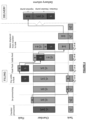
- the three chambers are operated in a rotating sequence so that:
- the cycles are staggered and are designed to produce (substantially) continuous flows rates in the supply and delivery columns.
- the timing of each step is determined by a PLC program that instructs valves to open or close.
- Pressure transmitters measure pressures in the chambers and supply and delivery manifold and, only if the pressure equalization with a safe margin has occurred, can the next step be performed.
- the upper part of the chamber can be kept full of clear-water, thus ensuring that the second, solids inlet or filling valve (120) is always closed in clear-water.
- the bottom by-pass duct (140) allows the fluid from the middle zone or the upper section of the chamber to flow directly to the bottom or lower section of the vertical chamber within a pile of solids.
- the bottom by-pass duct (140) provides a low resistance passage for water from above a pile of settled solids to a position within the pile and adjacent the bottom of the chamber.
- the arrangement and flow at an outlet of the by-pass duct (140) serve to fluidise and dilute the solids entering the fourth, solids outlet valve (128).
- the solids inside the pile are mobilised adjacent the high pressure solids and water outlet. It is, accordingly, the by-pass duct (140) that makes it possible to deliver the solids of the chamber is less than the full pumping cycle time allowing the fourth, solids outlet valve (128) to be well flushed before closing.
- the bottom by-pass duct (140) may be provided in various forms.
- the by-pass duct (140) is at least one pipe that extends within the chamber.
- the by-pass duct (140) extends from a first location above an opening of the transfer chute (130) to a second location adjacent the bottom end of the chamber.
- the by-pass duct (140) depends from (i.e. is secured to) the transfer chute (130), with an inlet to the by-pass duct (140) spaced upwardly from an outlet from the transfer chute (130).
- the lower (clear-water) tank collects the water from the constant head tank on the first level and a return pump lifts and returns this water to the upper clear-water tank.
- the upper (clear-water) tank provides storage and surge volume for displaced clear-water.
- the storage volume allows the injection pumps to be step controlled and provides the necessary net positive suction head required by the injection pumps.
- the high pressure injection pumps deliver the displaced clear-water back into the slurry delivery column. These pumps assist in moving the solids out of the delivery manifold, up through the delivery outlet bend and into the delivery column.
- positive-displacement plunger pumps are used for this duty, then as long as the slurry column resistance is not excessive (say due to a blockage), these pumps will deliver fluid into the column at the same pressure as the delivery manifold. Their delivery pressure will match "back-pressure" resistance of the delivery column requiring no other control.
- This injection feature eliminates the need for a separate column for displaced water.
- the water is "brought down once” via the supply column and is “pumped up once” in the slurry delivery column.
- the “water down” therefore only needs to match the "water up” as employed for displacement of the slurry.
- plunger pumps in parallel can provide variable capacity in steps. Clear-water, plunger pumps are ideally suited to this high pressure, low-volume duty.
- the injection pump connection to the delivery manifold will be fitted with non-return valve (NRV) mounted vertically as high as possible (or practical) from the slurry, such that the NRV will be seated so that solids gravitate down, away from the valve. This will be fitted to prevent unintended reverse flow from the slurry side to the clear-water side.
- NSV non-return valve
- the solids mass flow rate delivered can be infinitely varied by changing the speed of the feed that supplies the batching flasks.
- the average slurry concentration depends on the solids mass flow rate and the water volume flow rate in the delivery column.
- the volume in the delivery column depends on the supply flow rate, less the displaced volume plus the injected volume.
- the average injection pump flow rate needs to be controlled in steady state operation.
- the level in the lower- and upper-tanks is a proxy for the difference between the volumes displaced and injected and these levels should be managed in a suitable band that ensures water is available for the injection pumps and that there is spare capacity to receive clear-water.
- the control objective will be to operate the injection pumps and manage water levels so the average water supply flow from surface matches the average volume of water in the slurry to surface, thus maintaining continuity. If water from the water supply column is needed for other purposes underground, then this continuity will have to be suitably adjusted.
- a slurry mass flow meter (SFM) and a slurry density meter (SDM) are included downstream from the manifold to measure these parameters.
- SFM slurry mass flow meter
- SDM slurry density meter
- the duration of the "slug" flow (as a fraction of the chamber cycle time) can be varied to some extent by the size of the bottom by-pass duct (140) but should not exceed say 67% of the cycle to ensure good flushing with the last 33%.
- the invention provides for correct start-up from zero flow to through to the operating flow rate. Fitting the booster pump with a VSD ensures smooth start-up and acceleration of the water in the system. Once flowing smoothly with clear-water, solids can be added and the 3CHH brought into "normal slurry delivery" mode.
- Pressure equalization (within a small margin) will be achieved before opening of valves to avoid sudden large transient flows and associated pressure surges. This is one of the fundamental requirements for safe and smooth operation of the system. This will be achieved by ensuring that it is mechanically impossible for an actuator to open or close a valve if pressure equalization is not achieved within a small margin.
- the invention provides for correct filling and air removal from columns, valves, connecting pipes and chambers and for smooth, continuous cycling of the chambers achieving constant flow rates in both columns and without significant pressure surges.
- the 3CHH core is controlled by the PLC in a series of steps. Before advancing to the next step a check is made that all conditions necessary for safety are met. The timing of the total cycle time is synchronized with the rotary distributor via the encoder and VSD on the motor.
- a column flush valve is provided in a branch that connects the supply column to a line downstream from the injection pumps and allows the slurry delivery column to be flushed clean of all solids if the 3CHH core is paused or is otherwise non-operational.
- the CFV When actuated, the CFV by-passes the 3CHH core and directs the booster pump supply water to flush the slurry delivery column.
- Flushing the solids out of the slurry column with clear-water supplied from the surface booster pump is the preferred way to shut-down the 3CHH and facilitate an easy restart when required.
- the invention provides for correct flushing of the slurry delivery column of all solids before slowing the flow rates to zero. This is the reverse of the start-up procedure where the delivery column is flushed with clear-water by opening a CFV and pausing the chamber cycling.
- the CFV must also be able to open at the correct speed (not too fast or too slow) in the event of a loss of power underground.
- the approach ensures the chambers are always by-passed with flushing water until the delivery column is flushed of solids and thereafter the surface booster pumps can be stopped in a controlled manner.
- the slurry delivery column must be drained, either as part of a normal maintenance procedure, or in emergency in the event of a loss of both surface and underground pumping flows.
- the next course of action is to drain the column in a controlled manner via the Column Drain Valve (CDV), dissipate the pressure energy in a dissipater and deposits the solids in place where they can be loaded back on to a conveyor once drained and divert the dirty-water in the dirty-water collection sump.
- CDV Column Drain Valve
- the CDV must open rapidly (less than about 1 second), without electrical power or controls, if pressure surges are to be avoided.
- Surge anticipation valves SAV
- the CDV must be leak-tight in the presence of solids and the dissipater must drain the column at more-or-less constant (controlled) rate despite the contents varying from over-concentrated solids slurry due to settling or "slugs" through to almost clear-water to avoid excessive velocities and the associated wear.
- a chamber (D) is shown that departs from the configuration indicated in the schematic drawing of Figure 2 , where the high pressure inlet and low pressure outlet are indicated on opposite sides.
- a primary connection (200) is provided into the top end (202) of the chamber (D).
- the primary connection is provided by a vertical pipe (200) that with a second, low pressure solids inlet valve (204) located at a top of the vertical pipe (200).
- the second valve (204) is isolated from the interior of the vertical pipe (200) with a transfer chute (206) that extends concentrically along the inside of the vertical pipe (200) and into the chamber (D), as required.
- a secondary connection (207) is provided by a lateral pipe (207) that extends into a side of the vertical pipe (200).
- a high pressure water inlet (208) with a first valve (210) and a low pressure water outlet (212) with third valve (214) are connected to the secondary connection (206) for communication with the chamber (D) through the primary connection (200), around the transfer chute (206).
- the high pressure inlet (208) will be connected to a supply conduit (216) and the low pressure outlet (212) has a constant level arrangement (218) that serves to keep the second valve (204) submerged.
- the remainder of the chamber (D) may be as described above but of variable height depending on the application.
- valves at top of the chamber and particularly the first, high pressure water inlet valve (210) and the third, low pressure solids outlet valve (214) may have a clear-water volume provided in the respective inlet and outlet pipes, which in this case chare the secondary connection (207), to and from the chamber (D).
- the 3CHH brings together several technologies that must operate in concert under the direction of a control system. These technologies include:
- the physics of vertical hydro transport of coarse settling-solids for any solids mass flow rate determines the velocities in the delivery column and hence the supply water volume flow rate.
- the hydro transport operating parameters are therefore to be controlled within a safe, low-wear and/or energy-efficient operating envelope.
- the invention incorporates a control system provided to achieve the following operations as described in this specification:
- the system is suited to run smoothly and continuously.
- the system also accommodates a varied choice of the cycle time and chamber volume. This in turn affects the number of valve cycles or operations in a period.
- the system valves operate in clear-water and seal effectively with minimal wear, damage or leaking for hundreds of thousands of cycles.
- the column wear is strongly determined by the velocity of the slurry but can be reduced by including an appropriate lining (HDPE, polyurethane, rubber, ceramic materials or high-chromium steels, for example).
- HDPE high-chromium steels
- velocities need to be as low as possible and the slurry column operating hours minimized.
- the system can operate at lower speeds when this is all that is needed. Larger chambers with long cycles and fewer operations per year have a benefit if the system can be made to run faster when needed.
- the system improves reliability and reduces risk through the following elements:
- the operating efficiency (defined as power to lift solids / power into pump motors) is estimated to be in excess of 50%.
- the invention is estimated to make possible the hydro hoisting of about 1.4 Million tonnes per annum (Mtpa) of rock with a specific gravity (SG) of about 2.8, crushed to 20 mm or less, from a depth of around 1600 m to surface.
- the 3CHH is not expected to perform more than 250 000 cycles per year to deliver the estimated 1.4 Mtpa.
- the 3CHH system serves to ensure that all chamber valves are reliably closed in clear-water and therefore can seal effectively with low-maintenance requirements. This avoids the technical challenge of ensuring "a leak-tight" closure between the valve poppet (or closure) and seat in the presence of solids and high pressure differentials. The problem is eliminated.
- the apparatus of the invention provides superior reliability due to valves closing in clear-water, relatively few components, relatively low volumes to be pumped and intrinsic high efficiency. Ultimately, extra valve or pump motions or energy not used to lift solids, contributes to wear. The invention avoids this.
- the invention disclosed accordingly provides for a dry-solids or wet-solids fed, gravity-filled, bottom-discharge, vertically-arranged, 3 Chamber Hydro Hoist (3CHH), as an alternate solution to that which is offered by the prior art.
- 3CHH 3 Chamber Hydro Hoist
- the transfer chute in the illustrated example of the invention extends inside the chamber from the top end but could alternatively enter from a side of the chamber and be arranged at a suitable incline or with a suitable downward curve.
- the invention also allows for wet-solids to be fed into the 3CHH via a transfer chute under a suitable (low) pressure that is achieved from a pump rather than relying on the preferred gravity feed arrangement. This will avoid the need for a constant level arrangement associated with the low pressure solids outlet.
- Both the low- and high pressure control valves will preferably be actuated non-return valves with an internal pressure equalization function, but other types are possible.
- the invention accordingly involves a solids fed, gravity-filled, bottom-discharge, vertically arranged, 3 Chamber Hydro Hoist (3CHH) which achieves valve closure in clear-water by passing solids into and out of the chambers in a fraction of the "solids filling cycle” and “slurry delivery cycle” periods followed by flushing with clear-water before closing.
- 3CHH 3 Chamber Hydro Hoist
- the arrangement may involve the use of one, two, or even four chambers that employ a source of high pressure fluid to displace a slurry, depending on a particular application or given circumstances.
- the by-pass duct is shown extending (approximately) from the middle zone to the lower section.
- a by-pass duct could also be connected from the upper section to the lower section. Testing has indicated that the simplicity of a low profile, centrally arranged transfer chute and by-pass duct as currently disclosed may be a preferred embodiment.
- the invention however also allows for the inclusion of suitable flow-resistance devices to be provided above a lower section of the chamber to maintain a (substantially) clear-water environment at a top zone or upper section of the chamber.
- the flow-resistance devices serve to provide a uniform velocity profile with a flat interface (or front) as the fines rise or drift up with the displaced water from the lower section.
- the purpose is to prevent any irregular migration of the fines into the top section of the chamber (where they could otherwise be carried ahead by an irregular flow pattern caused by the falling solids).
- These flow-resistance devices could be provided at two spaced apart levels in the chamber, for example.
- the portion of the chamber below the flow-resistance devices would be the lower section and the portion of the chamber between the flow-resistance devices would be the middle zone.
- the transfer chute would extend past the flow-resistance devices to the lower section.
- the flow-resistance devices would serve to deter rising of mixed fines to maintain an upper layer or section of clear-water, free of any solids or fines.
- the flow-resistance devices may be provided as orifice plates. A suitable stack of tubes or some other alternative that equalizes and evens out the flow could also be used.
- the equipment of the invention may be employed in other slurry transport applications that are not limited to vertical hoisting in the mining industry.
- the invention may accordingly be used in relation to other particulate material.
- the particulate material is generally referred to as "rock” or “solids” for convenience sake and given the context of the embodiment. This should not be interpreted as a limitation.
- slug as used to refer to a batch of rock or solids introduced into the pipelines as slurry and will be understood by those skilled in the art.
Landscapes
- Engineering & Computer Science (AREA)
- Mechanical Engineering (AREA)
- Mining & Mineral Resources (AREA)
- Life Sciences & Earth Sciences (AREA)
- General Life Sciences & Earth Sciences (AREA)
- Geochemistry & Mineralogy (AREA)
- Geology (AREA)
- Treatment Of Sludge (AREA)
Claims (15)
- Zuführungsanordnung (102) zur Einbringung von Feststoffen zwischen einer Hochdruckwasserversorgung und einer Schlammabgabeleitung (138) in ein Schlammtransportsystem (100) umfassend mindestens eine mit Wasser gefüllte Kammer (A, B, C) mit einem oberen Ende (110) und einem unteren Ende (112), die Kammer einschließend:a. einen Hochdruckwassereinlass (114) am oberen Ende, der von einem ersten Ventil (116) gesteuert wird;b. einen Niederdruckfeststoffeinlass (118), der von einem zweiten Ventil (120) gesteuert wird, um Feststoffe in die mit Wasser gefüllte Kammer einzubringen;c. einen Niederdruckwasserauslass (122) am oberen Ende, der von einem dritten Ventil (124) für verdrängtes Wasser gesteuert wird, wenn der Feststoffeinlass geöffnet ist; undd. das untere Ende der Kammer mit einem Hochdruckfeststoff- und - wasserauslass (126), der von einem vierten Ventil (128) gesteuert wird und mit der Schlammabgabeleitung (138) verbunden ist;dadurch gekennzeichnet, dassder Niederdruckfeststoffeinlass eine Übergabeschurre (130) aufweist, die sich an einer Position in einem angemessenen Abstand zum oberen Ende der Kammer öffnet, um eine im Wesentlichen klare Wasserumgebung am oder neben dem oberen Ende der Kammer aufrechtzuerhalten;der Hochdruckwassereinlass und der Hochdruckfeststoff- und - wasserauslass geöffnet werden, um die Feststoffe aus der Kammer zu evakuieren; undder Hochdruckfeststoff- und -wasserauslass in einem Stadium geschlossen wird, in dem klares Wasser aus der Kammer austritt.
- Zuführungsanordnung (102) nach Anspruch 1, bei der die Übergabeschurre (130) in einen unteren Abschnitt (132) der Kammer (A, B, C) mündet.
- Zuführungsanordnung (102) nach Anspruch 2, bei der der Feststoffeinlass (118) neben dem oberen Ende (110) der Kammer (A, B, C) vorgesehen ist und durch das obere Ende der Kammer eintritt, wobei die Übergabeschurre (130) sich von dem oberen Ende innerhalb der Kammer erstreckt und ein Raum zwischen der Übergabeschurre und einem Kammerboden (112) vorgesehen ist, der ausreicht, um eine Charge von Feststoffen mit einem unterhalb der Übergabeschurre verbleibenden Freiraum aufzuschichten.
- Zuführungsanordnung (102) nach Anspruch 3, bei der der Feststoffeinlass (118) durch Schwerkraft gespeist wird, wobei das zweite Ventil (120) in einem Auslass eines Feststoffdosierkolbens (108) angeordnet ist.
- Zuführungsanordnung (102) nach Anspruch 2, bei der eine Wasserumgehungsleitung (140) sich von einer ersten Stelle oberhalb einer Öffnung der Übergabeschurre (130) zu einer zweiten Stelle neben dem unteren Ende (112) der Kammer (A, B, C) erstreckt.
- Zuführungsanordnung (102) nach Anspruch 5, bei der die Umgehungsleitung (140) mindestens ein Rohr ist, das sich innerhalb der Kammer (A, B, C) erstreckt und von der Übergabeschurre (130) abhängt, wobei ein Einlass zu der Umgehungsleitung von einem Auslass aus der Übergabeschurre nach oben beabstandet ist.
- Zuführungsanordnung (102) nach Anspruch 1, bei der der Niederdruckwasserauslass (122) mit einer Gleichdruckanordnung (146) mit einem Wasserstand verbunden ist, der das zweite Ventil (120) im Niederdruckfeststoffeinlass (118) eingetaucht hält.
- Zuführungsanordnung (102) nach Anspruch 1, bei dera. ein primärer Anschluss (200) in das obere Ende (202) der Kammer (D) vorgesehen ist, über dem das zweite Ventil (204) angeordnet ist und durch das die Übergabeschurre (206) sich in die Kammer erstreckt;b. ein sekundärer Anschluss (207) vorgesehen ist, der sich in eine Seite des primären Anschlusses erstreckt;c. der Hochdruckwassereinlass (208) und dem Niederdruckwasserauslass (212) mit dem sekundären Anschluss verbunden sind, um über den primären Anschluss mit der Kammer um die Übergabeschurre herum zu kommunizieren.
- Zuführungsanordnung (102) nach Anspruch 1, bei der der Niederdruckwasserauslass (122) angeschlossen ist, um mindestens eine Injektionspumpe (136) zu speisen, die in einer Hochdruckrücklaufleitung angeordnet ist, die das Wasser wieder in das Schlammtransportsystem (100) einbringt.
- Zuführungsanordnung (102) nach Anspruch 1, die zwei oder mehr Kammern (A, B, C) umfasst, die vertikal abgestützt und parallel in einer benachbarten Konfiguration angeordnet sind, wobei jede mit einem Hochdruckfeststoff- und - wasserauslass (126) versehen ist, die getrennt in einen Verteiler (156) münden, der mit der Abgabeleitung (138) verbunden ist.
- Zuführungsanordnung (102) nach Anspruch 10, bei der das Schlammtransportsystem ein Hydrohebezeug (100) mit einer Klarwasserversorgungsleitung (139) ist, die von einer an eine Druckerhöhungspumpe (134) angeschlossenen Eingangssäule (104) bereitgestellt wird, und die Schlammabgabeleitung (138) von einer Ausgangssäule (106) bereitgestellt wird.
- Verfahren zum Einspeisen von Feststoffen in ein Schlammtransportsystem (100) zwischen einer Hochdruckwasserversorgung und einer Schlammabgabeleitung (138), umfassend:a. Einbringen von Feststoffen in eine mit Wasser gefüllte Kammer (A, B, C);b. Öffnen eines Hochdruckeinlasses (144) neben dem Oberteil der Kammer und eines Hochdruckauslasses (126) von einem Boden (112) der Kammer, um die Feststoffe aus der Kammer zu evakuieren; undc. Richten der Feststoffe in die Schlammabgabeleitung (138);dadurch gekennzeichnet, dassd. die Feststoffe in die mit Wasser gefüllte Kammer (A, B, C)i. an einer Position in einem angemessenen Abstand zu einem oberen Ende der Kammer eingebracht werden,ii. ein Klarwasserbereichs neben dem Oberteil der Kammer aufrechterhalten wird;e. während durch die Feststoffe verdrängtes klares Wasser sich aus der Kammer durch einen Niederdruckauslass (122) neben dem oberen Ende der Kammer bewegen kann; undf. der Hochdruckfeststoff- und -wasserauslass in einem Stadium geschlossen wird, in dem klares Wasser aus der Kammer austritt.
- Verfahren nach Anspruch 12, bei dem die Feststoffe durch Schwerkraft in die Kammer (A, B, C) eingespeist werden.
- Verfahren nach Anspruch 13, bei dem eine Charge von Feststoffen in die Kammer (A, B, C) in einem ersten Teil einer Niederdruckkammer-Füllzykluszeit eingebracht wird und die verbleibende Zeit der Kammer-Füllzykluszeit dazu verwendet wird:um die Feststoffe und die dazugehörigen Feinstoffe in der Charge abzusetzen und unter Schwerkraft nach unten wandern zu lassen; und/oderum einen Feststoffdosierkolben (108) und ein Feststoffeinlassventil (120) zu spülen.
- Verfahren nach Anspruch 12, bei dem die Feststoffe in einen unteren Abschnitt (132) der Kammer (A, B, C) durch eine Übergabeschurre (130) abgegeben werden, eine Boden-Umgehungsleitung (140) verwendet wird, um einen Durchgang mit geringem Widerstand für Wasser von oberhalb eines Haufens abgesetzter Feststoffe zu einer Position innerhalb des Haufens und neben dem Boden (112) der Kammer bereitzustellen, und der Niederdruckwasserauslass (122) mit einer Gleichdruckanordnung (146) verbunden ist, wobei ein Stand vorgesehen ist, um ein Feststoffeinlassventil (120) in einem Niederdruckfeststoffeinlass (118) eingetaucht zu halten.
Applications Claiming Priority (2)
| Application Number | Priority Date | Filing Date | Title |
|---|---|---|---|
| ZA201805859 | 2018-08-31 | ||
| PCT/IB2019/057392 WO2020044322A1 (en) | 2018-08-31 | 2019-09-02 | Transport and hoisting of slurry |
Publications (4)
| Publication Number | Publication Date |
|---|---|
| EP3844087A1 EP3844087A1 (de) | 2021-07-07 |
| EP3844087A4 EP3844087A4 (de) | 2022-05-04 |
| EP3844087C0 EP3844087C0 (de) | 2024-12-11 |
| EP3844087B1 true EP3844087B1 (de) | 2024-12-11 |
Family
ID=69643400
Family Applications (1)
| Application Number | Title | Priority Date | Filing Date |
|---|---|---|---|
| EP19853808.4A Active EP3844087B1 (de) | 2018-08-31 | 2019-09-02 | Transport und heben von schlamm |
Country Status (6)
| Country | Link |
|---|---|
| US (1) | US11597613B2 (de) |
| EP (1) | EP3844087B1 (de) |
| AU (1) | AU2019329909B2 (de) |
| PL (1) | PL3844087T3 (de) |
| WO (1) | WO2020044322A1 (de) |
| ZA (1) | ZA202102095B (de) |
Families Citing this family (2)
| Publication number | Priority date | Publication date | Assignee | Title |
|---|---|---|---|---|
| WO2021018468A1 (en) * | 2019-07-30 | 2021-02-04 | British Telecommunications Public Limited Company | Duct blockage risk location prediction |
| PE20241525A1 (es) * | 2021-08-30 | 2024-07-22 | Global Met Tech Pty Ltd | Un sistema de manejo de medios y un metodo relacionado |
Family Cites Families (8)
| Publication number | Priority date | Publication date | Assignee | Title |
|---|---|---|---|---|
| US1576617A (en) * | 1925-05-01 | 1926-03-16 | Prince John | Sand dewatering and mixing device |
| BE750255A (fr) * | 1969-05-13 | 1970-10-16 | Snam Progetti | Dispositif et appareil adapte au transfert pulse et controle desolides en phase liquide |
| ZA72948B (en) * | 1971-02-26 | 1973-03-28 | Rst Int Metals Ltd | Improvements in or relating to pumps |
| DE2625513C3 (de) | 1976-06-05 | 1979-09-06 | Klein, Schanzlin & Becker Ag, 6710 Frankenthal | Rohrkammeraufgeber |
| US4699548A (en) | 1983-12-19 | 1987-10-13 | Howden Environmental Systems, Inc. | Slurry conveying system |
| GB0716664D0 (en) * | 2007-08-24 | 2007-10-03 | Dps Bristol Holdings Ltd | Method and apparatus for transporting a particulate material |
| US20100243252A1 (en) * | 2009-03-31 | 2010-09-30 | Rajesh Luharuka | Apparatus and Method for Oilfield Material Delivery |
| WO2021124262A1 (en) * | 2019-12-18 | 2021-06-24 | Peter Duncan Fraser | Hoisting of underwater solids |
-
2019
- 2019-09-02 PL PL19853808.4T patent/PL3844087T3/pl unknown
- 2019-09-02 US US17/272,593 patent/US11597613B2/en active Active
- 2019-09-02 EP EP19853808.4A patent/EP3844087B1/de active Active
- 2019-09-02 WO PCT/IB2019/057392 patent/WO2020044322A1/en not_active Ceased
- 2019-09-02 AU AU2019329909A patent/AU2019329909B2/en active Active
-
2021
- 2021-03-26 ZA ZA2021/02095A patent/ZA202102095B/en unknown
Also Published As
| Publication number | Publication date |
|---|---|
| EP3844087C0 (de) | 2024-12-11 |
| WO2020044322A1 (en) | 2020-03-05 |
| PL3844087T3 (pl) | 2025-06-09 |
| AU2019329909B2 (en) | 2026-03-05 |
| ZA202102095B (en) | 2025-11-26 |
| AU2019329909A1 (en) | 2021-04-29 |
| EP3844087A4 (de) | 2022-05-04 |
| US11597613B2 (en) | 2023-03-07 |
| EP3844087A1 (de) | 2021-07-07 |
| US20210371216A1 (en) | 2021-12-02 |
Similar Documents
| Publication | Publication Date | Title |
|---|---|---|
| US3560053A (en) | High pressure pumping system | |
| AU2013299746B2 (en) | Wellbore desanding system | |
| ES2939471T3 (es) | Sistema de bombeo | |
| US4978251A (en) | Method and apparatus for conveying materials in bulk by liquid pressure | |
| AU2019329909B2 (en) | Transport and hoisting of slurry | |
| CN104487715A (zh) | 操作多相泵及其设备的方法 | |
| CN1202569A (zh) | 一种高浓度和膏体矿山充填工艺及设备 | |
| US3485534A (en) | Deep mine ore retrieval system | |
| US3981541A (en) | Shallow underground coal slurry concentration sump | |
| JP7769796B2 (ja) | 分配マニホールド、媒体投入装置、圧力交換チャンバーポンプシステム、および圧力交換チャンバーポンプシステムを動作させる方法 | |
| RU2463453C1 (ru) | Способ гидротранспортирования закладочной пульпы в выработанное пространство | |
| CN116648415A (zh) | 双闸式骨料混料机,骨料传输系统以及其操作方法 | |
| WO2021124262A1 (en) | Hoisting of underwater solids | |
| BR112021000560B1 (pt) | Sistema de bombeamento | |
| KR102332489B1 (ko) | 석탄재의 회처리 장치 및 방법 | |
| FI97213B (fi) | Laite irtonaisen materiaalin hydraulista siirtämistä varten | |
| RU2310102C2 (ru) | Способ подъема многокомпонентной смеси с больших глубин и система для его реализации | |
| RU2067072C1 (ru) | Способ загрузки грунта в напорный трубопровод гидротранспортной установки и устройство для его осуществления | |
| JPH02265816A (ja) | 上向き管路の閉塞解除方法 | |
| JPH03223023A (ja) | バラ材料の水力搬送装置 | |
| JPS60209431A (ja) | スラリ−輸送装置 | |
| Dierks et al. | Developing a lock-hopper feeder for hydraulic hoisting of coal | |
| CN121676022A (zh) | 一种多功能离层注浆高速制充系统 | |
| PL226064B1 (pl) | Sposob i uklad do wspomagania przeplywu mediow, podczas plukania rurociagow podsadzkowych | |
| EP3689437A1 (de) | Sandfänger |
Legal Events
| Date | Code | Title | Description |
|---|---|---|---|
| STAA | Information on the status of an ep patent application or granted ep patent |
Free format text: STATUS: THE INTERNATIONAL PUBLICATION HAS BEEN MADE |
|
| STAA | Information on the status of an ep patent application or granted ep patent |
Free format text: STATUS: REQUEST FOR EXAMINATION WAS MADE |
|
| PUAI | Public reference made under article 153(3) epc to a published international application that has entered the european phase |
Free format text: ORIGINAL CODE: 0009012 |
|
| 17P | Request for examination filed |
Effective date: 20210326 |
|
| AK | Designated contracting states |
Kind code of ref document: A1 Designated state(s): AL AT BE BG CH CY CZ DE DK EE ES FI FR GB GR HR HU IE IS IT LI LT LU LV MC MK MT NL NO PL PT RO RS SE SI SK SM TR |
|
| DAV | Request for validation of the european patent (deleted) | ||
| DAX | Request for extension of the european patent (deleted) | ||
| A4 | Supplementary search report drawn up and despatched |
Effective date: 20220407 |
|
| RIC1 | Information provided on ipc code assigned before grant |
Ipc: E21F 13/00 20060101ALI20220401BHEP Ipc: E21F 13/04 20060101ALI20220401BHEP Ipc: B65G 53/30 20060101AFI20220401BHEP |
|
| GRAP | Despatch of communication of intention to grant a patent |
Free format text: ORIGINAL CODE: EPIDOSNIGR1 |
|
| STAA | Information on the status of an ep patent application or granted ep patent |
Free format text: STATUS: GRANT OF PATENT IS INTENDED |
|
| RIC1 | Information provided on ipc code assigned before grant |
Ipc: E21F 13/00 20060101ALI20240328BHEP Ipc: E21F 13/04 20060101ALI20240328BHEP Ipc: B65G 53/30 20060101AFI20240328BHEP |
|
| INTG | Intention to grant announced |
Effective date: 20240424 |
|
| GRAS | Grant fee paid |
Free format text: ORIGINAL CODE: EPIDOSNIGR3 |
|
| GRAA | (expected) grant |
Free format text: ORIGINAL CODE: 0009210 |
|
| STAA | Information on the status of an ep patent application or granted ep patent |
Free format text: STATUS: THE PATENT HAS BEEN GRANTED |
|
| AK | Designated contracting states |
Kind code of ref document: B1 Designated state(s): AL AT BE BG CH CY CZ DE DK EE ES FI FR GB GR HR HU IE IS IT LI LT LU LV MC MK MT NL NO PL PT RO RS SE SI SK SM TR |
|
| REG | Reference to a national code |
Ref country code: GB Ref legal event code: FG4D |
|
| REG | Reference to a national code |
Ref country code: CH Ref legal event code: EP |
|
| REG | Reference to a national code |
Ref country code: IE Ref legal event code: FG4D |
|
| REG | Reference to a national code |
Ref country code: DE Ref legal event code: R096 Ref document number: 602019063481 Country of ref document: DE |
|
| U01 | Request for unitary effect filed |
Effective date: 20250108 |
|
| U07 | Unitary effect registered |
Designated state(s): AT BE BG DE DK EE FI FR IT LT LU LV MT NL PT RO SE SI Effective date: 20250116 |
|
| PG25 | Lapsed in a contracting state [announced via postgrant information from national office to epo] |
Ref country code: HR Free format text: LAPSE BECAUSE OF FAILURE TO SUBMIT A TRANSLATION OF THE DESCRIPTION OR TO PAY THE FEE WITHIN THE PRESCRIBED TIME-LIMIT Effective date: 20241211 |
|
| PG25 | Lapsed in a contracting state [announced via postgrant information from national office to epo] |
Ref country code: ES Free format text: LAPSE BECAUSE OF FAILURE TO SUBMIT A TRANSLATION OF THE DESCRIPTION OR TO PAY THE FEE WITHIN THE PRESCRIBED TIME-LIMIT Effective date: 20241211 |
|
| PG25 | Lapsed in a contracting state [announced via postgrant information from national office to epo] |
Ref country code: NO Free format text: LAPSE BECAUSE OF FAILURE TO SUBMIT A TRANSLATION OF THE DESCRIPTION OR TO PAY THE FEE WITHIN THE PRESCRIBED TIME-LIMIT Effective date: 20250311 |
|
| PG25 | Lapsed in a contracting state [announced via postgrant information from national office to epo] |
Ref country code: GR Free format text: LAPSE BECAUSE OF FAILURE TO SUBMIT A TRANSLATION OF THE DESCRIPTION OR TO PAY THE FEE WITHIN THE PRESCRIBED TIME-LIMIT Effective date: 20250312 |
|
| PG25 | Lapsed in a contracting state [announced via postgrant information from national office to epo] |
Ref country code: RS Free format text: LAPSE BECAUSE OF FAILURE TO SUBMIT A TRANSLATION OF THE DESCRIPTION OR TO PAY THE FEE WITHIN THE PRESCRIBED TIME-LIMIT Effective date: 20250311 |
|
| PG25 | Lapsed in a contracting state [announced via postgrant information from national office to epo] |
Ref country code: SM Free format text: LAPSE BECAUSE OF FAILURE TO SUBMIT A TRANSLATION OF THE DESCRIPTION OR TO PAY THE FEE WITHIN THE PRESCRIBED TIME-LIMIT Effective date: 20241211 |
|
| PG25 | Lapsed in a contracting state [announced via postgrant information from national office to epo] |
Ref country code: IS Free format text: LAPSE BECAUSE OF FAILURE TO SUBMIT A TRANSLATION OF THE DESCRIPTION OR TO PAY THE FEE WITHIN THE PRESCRIBED TIME-LIMIT Effective date: 20250411 |
|
| PG25 | Lapsed in a contracting state [announced via postgrant information from national office to epo] |
Ref country code: SK Free format text: LAPSE BECAUSE OF FAILURE TO SUBMIT A TRANSLATION OF THE DESCRIPTION OR TO PAY THE FEE WITHIN THE PRESCRIBED TIME-LIMIT Effective date: 20241211 |
|
| PG25 | Lapsed in a contracting state [announced via postgrant information from national office to epo] |
Ref country code: CZ Free format text: LAPSE BECAUSE OF FAILURE TO SUBMIT A TRANSLATION OF THE DESCRIPTION OR TO PAY THE FEE WITHIN THE PRESCRIBED TIME-LIMIT Effective date: 20241211 |
|
| PGFP | Annual fee paid to national office [announced via postgrant information from national office to epo] |
Ref country code: PL Payment date: 20250901 Year of fee payment: 7 |
|
| PLBE | No opposition filed within time limit |
Free format text: ORIGINAL CODE: 0009261 |
|
| STAA | Information on the status of an ep patent application or granted ep patent |
Free format text: STATUS: NO OPPOSITION FILED WITHIN TIME LIMIT |
|
| REG | Reference to a national code |
Ref country code: CH Ref legal event code: L10 Free format text: ST27 STATUS EVENT CODE: U-0-0-L10-L00 (AS PROVIDED BY THE NATIONAL OFFICE) Effective date: 20251022 |
|
| U20 | Renewal fee for the european patent with unitary effect paid |
Year of fee payment: 7 Effective date: 20250925 |
|
| 26N | No opposition filed |
Effective date: 20250912 |
|
| REG | Reference to a national code |
Ref country code: CH Ref legal event code: H13 Free format text: ST27 STATUS EVENT CODE: U-0-0-H10-H13 (AS PROVIDED BY THE NATIONAL OFFICE) Effective date: 20260425 |
|
| GBPC | Gb: european patent ceased through non-payment of renewal fee |
Effective date: 20250902 |
|
| PG25 | Lapsed in a contracting state [announced via postgrant information from national office to epo] |
Ref country code: MC Free format text: LAPSE BECAUSE OF FAILURE TO SUBMIT A TRANSLATION OF THE DESCRIPTION OR TO PAY THE FEE WITHIN THE PRESCRIBED TIME-LIMIT Effective date: 20241211 |
|
| PG25 | Lapsed in a contracting state [announced via postgrant information from national office to epo] |
Ref country code: GB Free format text: LAPSE BECAUSE OF NON-PAYMENT OF DUE FEES Effective date: 20250902 |
|
| PG25 | Lapsed in a contracting state [announced via postgrant information from national office to epo] |
Ref country code: IE Free format text: LAPSE BECAUSE OF NON-PAYMENT OF DUE FEES Effective date: 20250902 Ref country code: CH Free format text: LAPSE BECAUSE OF NON-PAYMENT OF DUE FEES Effective date: 20250930 |