EP3844093B1 - Hebemaschine, insbesondere zur handhabung von lasten - Google Patents
Hebemaschine, insbesondere zur handhabung von lasten Download PDFInfo
- Publication number
- EP3844093B1 EP3844093B1 EP19774155.6A EP19774155A EP3844093B1 EP 3844093 B1 EP3844093 B1 EP 3844093B1 EP 19774155 A EP19774155 A EP 19774155A EP 3844093 B1 EP3844093 B1 EP 3844093B1
- Authority
- EP
- European Patent Office
- Prior art keywords
- machine
- actuator
- chassis
- suspension assembly
- front axle
- Prior art date
- Legal status (The legal status is an assumption and is not a legal conclusion. Google has not performed a legal analysis and makes no representation as to the accuracy of the status listed.)
- Active
Links
Images


Classifications
-
- B—PERFORMING OPERATIONS; TRANSPORTING
- B66—HOISTING; LIFTING; HAULING
- B66F—HOISTING, LIFTING, HAULING OR PUSHING, NOT OTHERWISE PROVIDED FOR, e.g. DEVICES WHICH APPLY A LIFTING OR PUSHING FORCE DIRECTLY TO THE SURFACE OF A LOAD
- B66F9/00—Devices for lifting or lowering bulky or heavy goods for loading or unloading purposes
- B66F9/06—Devices for lifting or lowering bulky or heavy goods for loading or unloading purposes movable, with their loads, on wheels or the like, e.g. fork-lift trucks
- B66F9/065—Devices for lifting or lowering bulky or heavy goods for loading or unloading purposes movable, with their loads, on wheels or the like, e.g. fork-lift trucks non-masted
- B66F9/0655—Devices for lifting or lowering bulky or heavy goods for loading or unloading purposes movable, with their loads, on wheels or the like, e.g. fork-lift trucks non-masted with a telescopic boom
-
- B—PERFORMING OPERATIONS; TRANSPORTING
- B66—HOISTING; LIFTING; HAULING
- B66F—HOISTING, LIFTING, HAULING OR PUSHING, NOT OTHERWISE PROVIDED FOR, e.g. DEVICES WHICH APPLY A LIFTING OR PUSHING FORCE DIRECTLY TO THE SURFACE OF A LOAD
- B66F9/00—Devices for lifting or lowering bulky or heavy goods for loading or unloading purposes
- B66F9/06—Devices for lifting or lowering bulky or heavy goods for loading or unloading purposes movable, with their loads, on wheels or the like, e.g. fork-lift trucks
- B66F9/075—Constructional features or details
- B66F9/07586—Suspension or mounting of wheels on chassis
-
- B—PERFORMING OPERATIONS; TRANSPORTING
- B60—VEHICLES IN GENERAL
- B60G—VEHICLE SUSPENSION ARRANGEMENTS
- B60G13/00—Resilient suspensions characterised by arrangement, location or type of vibration dampers
- B60G13/02—Resilient suspensions characterised by arrangement, location or type of vibration dampers having dampers dissipating energy, e.g. frictionally
- B60G13/06—Resilient suspensions characterised by arrangement, location or type of vibration dampers having dampers dissipating energy, e.g. frictionally of fluid type
- B60G13/08—Resilient suspensions characterised by arrangement, location or type of vibration dampers having dampers dissipating energy, e.g. frictionally of fluid type hydraulic
-
- B—PERFORMING OPERATIONS; TRANSPORTING
- B60—VEHICLES IN GENERAL
- B60G—VEHICLE SUSPENSION ARRANGEMENTS
- B60G17/00—Resilient suspensions having means for adjusting the spring or vibration-damper characteristics, for regulating the distance between a supporting surface and a sprung part of vehicle or for locking suspension during use to meet varying vehicular or surface conditions, e.g. due to speed or load
- B60G17/015—Resilient suspensions having means for adjusting the spring or vibration-damper characteristics, for regulating the distance between a supporting surface and a sprung part of vehicle or for locking suspension during use to meet varying vehicular or surface conditions, e.g. due to speed or load the regulating means comprising electric or electronic elements
- B60G17/0152—Resilient suspensions having means for adjusting the spring or vibration-damper characteristics, for regulating the distance between a supporting surface and a sprung part of vehicle or for locking suspension during use to meet varying vehicular or surface conditions, e.g. due to speed or load the regulating means comprising electric or electronic elements characterised by the action on a particular type of suspension unit
-
- B—PERFORMING OPERATIONS; TRANSPORTING
- B60—VEHICLES IN GENERAL
- B60G—VEHICLE SUSPENSION ARRANGEMENTS
- B60G17/00—Resilient suspensions having means for adjusting the spring or vibration-damper characteristics, for regulating the distance between a supporting surface and a sprung part of vehicle or for locking suspension during use to meet varying vehicular or surface conditions, e.g. due to speed or load
- B60G17/015—Resilient suspensions having means for adjusting the spring or vibration-damper characteristics, for regulating the distance between a supporting surface and a sprung part of vehicle or for locking suspension during use to meet varying vehicular or surface conditions, e.g. due to speed or load the regulating means comprising electric or electronic elements
- B60G17/016—Resilient suspensions having means for adjusting the spring or vibration-damper characteristics, for regulating the distance between a supporting surface and a sprung part of vehicle or for locking suspension during use to meet varying vehicular or surface conditions, e.g. due to speed or load the regulating means comprising electric or electronic elements characterised by their responsiveness, when the vehicle is travelling, to specific motion, a specific condition, or driver input
-
- B—PERFORMING OPERATIONS; TRANSPORTING
- B60—VEHICLES IN GENERAL
- B60G—VEHICLE SUSPENSION ARRANGEMENTS
- B60G17/00—Resilient suspensions having means for adjusting the spring or vibration-damper characteristics, for regulating the distance between a supporting surface and a sprung part of vehicle or for locking suspension during use to meet varying vehicular or surface conditions, e.g. due to speed or load
- B60G17/06—Characteristics of dampers, e.g. mechanical dampers
- B60G17/08—Characteristics of fluid dampers
-
- B—PERFORMING OPERATIONS; TRANSPORTING
- B60—VEHICLES IN GENERAL
- B60G—VEHICLE SUSPENSION ARRANGEMENTS
- B60G9/00—Resilient suspensions of a rigid axle or axle housing for two or more wheels
- B60G9/02—Resilient suspensions of a rigid axle or axle housing for two or more wheels the axle or housing being pivotally mounted on the vehicle, e.g. the pivotal axis being parallel to the longitudinal axis of the vehicle
-
- B—PERFORMING OPERATIONS; TRANSPORTING
- B66—HOISTING; LIFTING; HAULING
- B66F—HOISTING, LIFTING, HAULING OR PUSHING, NOT OTHERWISE PROVIDED FOR, e.g. DEVICES WHICH APPLY A LIFTING OR PUSHING FORCE DIRECTLY TO THE SURFACE OF A LOAD
- B66F17/00—Safety devices, e.g. for limiting or indicating lifting force
- B66F17/003—Safety devices, e.g. for limiting or indicating lifting force for fork-lift trucks
-
- B—PERFORMING OPERATIONS; TRANSPORTING
- B66—HOISTING; LIFTING; HAULING
- B66F—HOISTING, LIFTING, HAULING OR PUSHING, NOT OTHERWISE PROVIDED FOR, e.g. DEVICES WHICH APPLY A LIFTING OR PUSHING FORCE DIRECTLY TO THE SURFACE OF A LOAD
- B66F9/00—Devices for lifting or lowering bulky or heavy goods for loading or unloading purposes
- B66F9/06—Devices for lifting or lowering bulky or heavy goods for loading or unloading purposes movable, with their loads, on wheels or the like, e.g. fork-lift trucks
- B66F9/075—Constructional features or details
- B66F9/07513—Details concerning the chassis
-
- B—PERFORMING OPERATIONS; TRANSPORTING
- B66—HOISTING; LIFTING; HAULING
- B66F—HOISTING, LIFTING, HAULING OR PUSHING, NOT OTHERWISE PROVIDED FOR, e.g. DEVICES WHICH APPLY A LIFTING OR PUSHING FORCE DIRECTLY TO THE SURFACE OF A LOAD
- B66F9/00—Devices for lifting or lowering bulky or heavy goods for loading or unloading purposes
- B66F9/06—Devices for lifting or lowering bulky or heavy goods for loading or unloading purposes movable, with their loads, on wheels or the like, e.g. fork-lift trucks
- B66F9/075—Constructional features or details
- B66F9/07559—Stabilizing means
-
- B—PERFORMING OPERATIONS; TRANSPORTING
- B66—HOISTING; LIFTING; HAULING
- B66F—HOISTING, LIFTING, HAULING OR PUSHING, NOT OTHERWISE PROVIDED FOR, e.g. DEVICES WHICH APPLY A LIFTING OR PUSHING FORCE DIRECTLY TO THE SURFACE OF A LOAD
- B66F9/00—Devices for lifting or lowering bulky or heavy goods for loading or unloading purposes
- B66F9/06—Devices for lifting or lowering bulky or heavy goods for loading or unloading purposes movable, with their loads, on wheels or the like, e.g. fork-lift trucks
- B66F9/075—Constructional features or details
- B66F9/0759—Details of operating station, e.g. seats, levers, operator platforms, cabin suspension
-
- F—MECHANICAL ENGINEERING; LIGHTING; HEATING; WEAPONS; BLASTING
- F15—FLUID-PRESSURE ACTUATORS; HYDRAULICS OR PNEUMATICS IN GENERAL
- F15B—SYSTEMS ACTING BY MEANS OF FLUIDS IN GENERAL; FLUID-PRESSURE ACTUATORS, e.g. SERVOMOTORS; DETAILS OF FLUID-PRESSURE SYSTEMS, NOT OTHERWISE PROVIDED FOR
- F15B15/00—Fluid-actuated devices for displacing a member from one position to another; Gearing associated therewith
- F15B15/08—Characterised by the construction of the motor unit
-
- B—PERFORMING OPERATIONS; TRANSPORTING
- B60—VEHICLES IN GENERAL
- B60G—VEHICLE SUSPENSION ARRANGEMENTS
- B60G13/00—Resilient suspensions characterised by arrangement, location or type of vibration dampers
- B60G13/14—Resilient suspensions characterised by arrangement, location or type of vibration dampers having dampers accumulating utilisable energy, e.g. compressing air
-
- B—PERFORMING OPERATIONS; TRANSPORTING
- B60—VEHICLES IN GENERAL
- B60G—VEHICLE SUSPENSION ARRANGEMENTS
- B60G2200/00—Indexing codes relating to suspension types
- B60G2200/30—Rigid axle suspensions
- B60G2200/32—Rigid axle suspensions pivoted
- B60G2200/322—Rigid axle suspensions pivoted with a single pivot point and a straight axle
-
- B—PERFORMING OPERATIONS; TRANSPORTING
- B60—VEHICLES IN GENERAL
- B60G—VEHICLE SUSPENSION ARRANGEMENTS
- B60G2200/00—Indexing codes relating to suspension types
- B60G2200/30—Rigid axle suspensions
- B60G2200/32—Rigid axle suspensions pivoted
- B60G2200/326—Rigid axle suspensions pivoted with two laterally spaced pivots, e.g. trailing frame
-
- B—PERFORMING OPERATIONS; TRANSPORTING
- B60—VEHICLES IN GENERAL
- B60G—VEHICLE SUSPENSION ARRANGEMENTS
- B60G2202/00—Indexing codes relating to the type of spring, damper or actuator
- B60G2202/20—Type of damper
- B60G2202/24—Fluid damper
-
- B—PERFORMING OPERATIONS; TRANSPORTING
- B60—VEHICLES IN GENERAL
- B60G—VEHICLE SUSPENSION ARRANGEMENTS
- B60G2202/00—Indexing codes relating to the type of spring, damper or actuator
- B60G2202/40—Type of actuator
- B60G2202/41—Fluid actuator
- B60G2202/413—Hydraulic actuator
-
- B—PERFORMING OPERATIONS; TRANSPORTING
- B60—VEHICLES IN GENERAL
- B60G—VEHICLE SUSPENSION ARRANGEMENTS
- B60G2204/00—Indexing codes related to suspensions per se or to auxiliary parts
- B60G2204/40—Auxiliary suspension parts; Adjustment of suspensions
- B60G2204/45—Stops limiting travel
-
- B—PERFORMING OPERATIONS; TRANSPORTING
- B60—VEHICLES IN GENERAL
- B60G—VEHICLE SUSPENSION ARRANGEMENTS
- B60G2204/00—Indexing codes related to suspensions per se or to auxiliary parts
- B60G2204/40—Auxiliary suspension parts; Adjustment of suspensions
- B60G2204/46—Means for locking the suspension
- B60G2204/4605—Means for locking the suspension hydraulically, e.g. interrupting communication between the chambers of a hydraulic cylinder
-
- B—PERFORMING OPERATIONS; TRANSPORTING
- B60—VEHICLES IN GENERAL
- B60G—VEHICLE SUSPENSION ARRANGEMENTS
- B60G2204/00—Indexing codes related to suspensions per se or to auxiliary parts
- B60G2204/62—Adjustable continuously, e.g. during driving
-
- B—PERFORMING OPERATIONS; TRANSPORTING
- B60—VEHICLES IN GENERAL
- B60G—VEHICLE SUSPENSION ARRANGEMENTS
- B60G2300/00—Indexing codes relating to the type of vehicle
- B60G2300/02—Trucks; Load vehicles
- B60G2300/022—Fork lift trucks, Clark
-
- B—PERFORMING OPERATIONS; TRANSPORTING
- B60—VEHICLES IN GENERAL
- B60G—VEHICLE SUSPENSION ARRANGEMENTS
- B60G2400/00—Indexing codes relating to detected, measured or calculated conditions or factors
- B60G2400/05—Attitude
- B60G2400/051—Angle
- B60G2400/0516—Angular position of a suspension element
-
- B—PERFORMING OPERATIONS; TRANSPORTING
- B60—VEHICLES IN GENERAL
- B60G—VEHICLE SUSPENSION ARRANGEMENTS
- B60G2400/00—Indexing codes relating to detected, measured or calculated conditions or factors
- B60G2400/20—Speed
- B60G2400/204—Vehicle speed
-
- B—PERFORMING OPERATIONS; TRANSPORTING
- B60—VEHICLES IN GENERAL
- B60G—VEHICLE SUSPENSION ARRANGEMENTS
- B60G2400/00—Indexing codes relating to detected, measured or calculated conditions or factors
- B60G2400/40—Steering conditions
- B60G2400/41—Steering angle
-
- B—PERFORMING OPERATIONS; TRANSPORTING
- B60—VEHICLES IN GENERAL
- B60G—VEHICLE SUSPENSION ARRANGEMENTS
- B60G2400/00—Indexing codes relating to detected, measured or calculated conditions or factors
- B60G2400/90—Other conditions or factors
-
- B—PERFORMING OPERATIONS; TRANSPORTING
- B60—VEHICLES IN GENERAL
- B60G—VEHICLE SUSPENSION ARRANGEMENTS
- B60G2500/00—Indexing codes relating to the regulated action or device
-
- B—PERFORMING OPERATIONS; TRANSPORTING
- B60—VEHICLES IN GENERAL
- B60G—VEHICLE SUSPENSION ARRANGEMENTS
- B60G2600/00—Indexing codes relating to particular elements, systems or processes used on suspension systems or suspension control systems
- B60G2600/18—Automatic control means
- B60G2600/182—Active control means
-
- F—MECHANICAL ENGINEERING; LIGHTING; HEATING; WEAPONS; BLASTING
- F15—FLUID-PRESSURE ACTUATORS; HYDRAULICS OR PNEUMATICS IN GENERAL
- F15B—SYSTEMS ACTING BY MEANS OF FLUIDS IN GENERAL; FLUID-PRESSURE ACTUATORS, e.g. SERVOMOTORS; DETAILS OF FLUID-PRESSURE SYSTEMS, NOT OTHERWISE PROVIDED FOR
- F15B2201/00—Accumulators
Definitions
- the invention relates to a lifting machine in particular for handling loads.
- a lifting machine comprising a chassis, a lifting arm mounted on said chassis, movable at least pivotally between a high position and a low position, at least one sensor for measuring the inclination of the lifting arm by relative to the chassis, said chassis being a rolling chassis equipped with at least one front axle and one rear axle, the rear axle being mounted pivoting around an axis parallel to the longitudinal axis of the machine, at least the one of the axles being a so-called suspended axle equipped with suspension.
- An aim of the invention is to propose a lifting machine whose design makes it possible to increase the driving comfort of the driver without harming the safety of the machine.
- the invention relates to a lifting machine according to claim 1.
- the machine has at least one configuration in which the pivoting rear axle is mounted free to pivot and the suspension fitted to the front axle is in the activated state for free mounting to pivot of the front axle. .
- the two axles are mounted free to pivot for optimal driving comfort without compromising the safety of the machine.
- the machine comprises a suspension activation/deactivation member operable by the driver of the machine.
- the machine comprises a control unit configured to control activation or deactivation of the suspension at least according to the data provided by the sensor measuring the inclination of the lifting arm.
- the suspension of the front axle comprises at least one hydraulic actuator arranged between the front axle and the chassis and connecting the front axle to the chassis, one or more shock absorbers, and at least one closable fluid connection between the the actuator and the shock absorber(s), said suspension being deactivated in the closed state of the fluid connection.
- control unit and/or the activation/deactivation member of the suspension operable by the driver of the machine are configured to control activation of the suspension by opening the fluid connection and deactivation of the suspension by closing the fluid connection.
- the machine comprises an actuator control device comprising an actuator control member operable by the driver of the machine and the control unit is configured to control the deactivation of the suspension in the activated state of the control member of the actuator operable by the driver of the machine.
- a tilt correction function can be performed using said actuator.
- the actuator control device comprises a hydraulic distributor interposed between a source of supply of pressurized fluid and the actuator, said distributor being mounted movable between positions comprising at least one position of non-supply of fluid to the actuator and positions of fluid supply of the actuator, said distributor being in the position of supply of fluid to the actuator in the actuated state of the control member of the actuator operable by the driver of the machine.
- the chassis comprises a driving cabin equipped with a floor
- the machine comprises a measuring sensor representative of the angle formed between the plane of the floor and the longitudinal axis of the front axle of the chassis
- the control unit is configured to, in the deactivated state of the suspension and not actuated of the control member of the actuator control device, prohibit activation of the suspension at least when the angle measured by the angle measurement sensor formed between the plane of the floor and the longitudinal axis of the front axle of the chassis is outside a predetermined angular range.
- the actuator is formed by a double-acting hydraulic cylinder or two single-acting hydraulic cylinders each arranged between the front axle and the chassis, the or each cylinder of the actuator comprises a body and a rod mounted movable to slide inside the body and dividing the body into two chambers and the rod of the or each cylinder is mounted freely to slide inside said cylinder body associated with the open state of the fluid connection closable between the actuator and the shock absorber(s).
- the or at least one, preferably each, of the shock absorbers is formed by a recoverable energy accumulator, such as a hydraulic or hydropneumatic accumulator, in particular a bladder or piston accumulator, or membrane.
- a recoverable energy accumulator such as a hydraulic or hydropneumatic accumulator, in particular a bladder or piston accumulator, or membrane.
- the machine comprises a sensor for measuring the speed of movement of the machine and a sensor for measuring the steering angle of the wheels of the front axle and the unit of control is configured to control a deactivation of the suspension at least according to the data provided by said sensors.
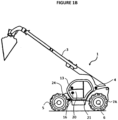
- This machine 1 is more particularly intended to allow the handling of loads.
- This machine 1 comprises a chassis 2 surmounted by a lifting arm 3.
- This lifting arm 3 can be a telescopic arm.
- the lifting arm 3 is generally equipped, at its free end, with a load handling tool such as a bucket, forks or other accessories.
- This lifting arm 3 is pivotally coupled to the chassis 2 for moving the lifting arm 3 between a high position and a low position.
- one or more actuators such as cylinders not shown, are provided between the lifting arm and the chassis 2 in a manner known per se, the pivoting taking place around a so-called horizontal axis, i.e. that is to say substantially parallel to the plane of the ground when the machine rests on a horizontal plane.
- This lifting arm 3 extends in the front/rear direction of the chassis 2 with its free end positioned beyond the front end of the chassis in the low position of the lifting arm 3.
- the pivot connection connecting the lifting arm 3 to the chassis 2 is therefore arranged closer to the rear of the machine than to the front of the machine 1.
- the machine 1 also includes a sensor 4 for measuring the inclination of the lifting arm 3 relative to the chassis 2.
- the chassis 2 of the machine includes a driving cabin 20 inside which a driver of the machine can take place.
- a driving cabin 20 inside which a driver of the machine can take place.
- the arm rests on a part of the chassis 2 next to the driving cabin 20.
- Chassis 2 of the machine is a rolling chassis equipped with a front axle 5 and a rear axle 6.
- the pivot connection coupling the lifting arm 3 to the chassis is arranged closer to the rear axle 6 than to the front axle 5.
- Each axle is equipped with wheels shown in 7B for the front axle 5 and in 7A for the rear axle 6.
- the rear axle 6 is a pivoting axle.
- the pivoting rear axle 6 is coupled to the chassis by a pivot connection whose axis is represented at 25en Figure 3 .
- This axis extends parallel to the horizontal longitudinal axis of the chassis of the machine in the flat positioned state of the machine or parallel to the front/rear direction of the machine.
- This rear axle 6 is mounted freely to pivot within an angular range delimited by two stops 8 carried by said chassis 2 and extending on said chassis on either side of the pivot connection 25 coupling the rear axle 6 to the chassis 2 above said connection.
- the pivoting rear axle 6 is mounted permanently free to pivot, that is to say that there are no means of blocking the pivoting connection between the rear axle and the chassis.
- the front axle 5 is also an oscillating axle coupled to the chassis by a pivot connection 26 with a pivot axis parallel to the longitudinal axis of the machine 1.
- the production of a pivoting or oscillating axle allows the wheels of the machine to better follow the ground profile, particularly in the case of irregular ground.
- This front axle 5 is equipped with a suspension 9 to cushion the pivoting movements of the front axle 5 relative to the chassis 2.
- This suspension 9 is an activatable/deactivatable suspension.
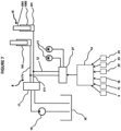
- This suspension 9 of the front axle 5 comprises a hydraulic actuator 10 disposed between the front axle 5 and the chassis 2 and connecting the front axle 5 to the chassis 2, shock absorbers 11 and a closable fluid connection 12 between the actuator 10 and the shock absorbers 11, the suspension 9 being deactivated in the closed state of the fluid connection 12.
- the actuator 10 can be formed from a double-acting hydraulic cylinder 100 as illustrated in figures 4 And 6 or two single-acting hydraulic cylinders 101 each arranged between the front axle 5 and the chassis 2 on either side of the pivot connection 26 as illustrated in figures 5 And 7 .
- this cylinder comprises a body 1000 and a rod 1001 movably mounted to slide inside the body 1000 and dividing the body 1000 into two chambers.
- the rod 1001 is coupled to the chassis 2 and the body 1000 to the front axle 5, or vice versa.
- the actuator 10 is therefore able to be acted upon during a movement relative to pivoting of the front axle and the chassis 2.
- the shock absorbers 11 are, for their part, each formed by a recoverable energy accumulator, such as a hydraulic or hydropneumatic accumulator, in particular a bladder, piston, or membrane accumulator or the like.
- a recoverable energy accumulator such as a hydraulic or hydropneumatic accumulator, in particular a bladder, piston, or membrane accumulator or the like.
- shock absorbers 11 are either connected, one to the chamber of one of the cylinders, the other to the chamber of the other cylinder when the actuator is an actuator formed of two single-acting cylinders 101 as in the example of the Figure 7 , or connected one to one of the chambers, the other to the other chamber of the cylinder when the actuator is a double-acting cylinder 100 as in the example shown in Figure 6 .
- Each damper 11 allows, when necessary, to store a pressurized fluid from the actuator 10 and then release it subsequently.
- the details of the operation of such accumulators will not be described in detail because they are well known to those skilled in this art.
- one of the shock absorbers allows damping when the front axle 5 pivots in a direction corresponding, for example, to an upward movement of the left front wheel while the other shock absorber allows damping when the axle 5 front pivots in a direction corresponding for example to an upward movement of the right front wheel.
- This fluid connection 12 comprises two fluid circulation lines which, in the case of a double-acting cylinder, connect, one, a chamber of said cylinder to one of the accumulators, the other, the other chamber of the cylinder to the other accumulator, or in the case of two single-acting cylinders, one, the so-called active chamber of one of the cylinders to one of the accumulators, the other, the so-called active chamber of the other of the cylinders to the other accumulator.
- This connection 12 can be closed by a closing system 27 which allows simultaneous closing of the two lines of the fluid connection 12.
- this shutter system 27 is formed by a distributor which in one of its positions closes these two lines, and in another of its positions opens the two lines forming the fluid connection 12 between the accumulators and the actuator.
- this shutter system 27 could have been replaced by two solenoid valves with synchronized actuation and each arranged on one of the lines of the fluid connection 12.
- the rod 1001 of the cylinder in the case of a double-acting cylinder, or of each cylinder, in the case of two single-acting cylinders, is mounted freely to slide at the interior of the body of the associated cylinder so that as soon as the cylinder is stressed, due to the relative pivoting movement between the chassis and the front axle, part of the fluid contained in the cylinder is transferred to the associated accumulator causing damping of the relative pivoting movement of the front axle and the chassis 2.
- the front and rear axles can be mounted free to pivot.
- the suspension is deactivated at least when the angle value measured by the sensor 4 for measuring the inclination of the lifting arm 3 is greater than a predetermined threshold value.
- the machine 1 comprises a control unit 14 configured to control an activation or deactivation of the suspension 9 at least as a function of the data provided by the sensor 4 for measuring the inclination of the lifting arm 3.
- This control unit 4 is in the form of an electronic and/or computer system which includes for example a microprocessor and a working memory. According to a particular aspect, the control unit can be in the form of a programmable controller.
- the functions and steps described can be implemented in the form of a computer program or via hardware components (e.g. programmable gate arrays).
- the functions and steps operated by the control unit or its modules can be carried out by instruction sets or computer modules implemented in a processor or controller or be carried out by dedicated electronic components or FPGA type components or ASIC. It is also possible to combine computer parts and electronic parts.
- the unit or means or modules of said unit are configured to carry out a given operation
- the machine can also include a member 13 for activating/deactivating the suspension 9 operable by the driver of the machine 1.
- This activation/deactivation member 13 can be formed by a simple control button placed on the dashboard of the machine or on a control member, such as a joystick, placed inside the cabin 20 of the machine and allowing the actuation of the lifting arm 3 and the advancement of the machine 1.
- the control unit 14 and/or the member 13 for activating/deactivating the suspension 9 operable by the driver of the machine are configured to control activation of the suspension 9 by opening of the fluidic connection 12 and deactivation of the suspension 9 by closing the fluid connection 12.
- the control unit 14 and/or the member 13 for activating/deactivating the suspension 9 operable by the driver of the machine are configured so that the fluid connection 12 is open to the activated state of the suspension 9 and the fluid connection 12 is closed in the deactivated state of the suspension 9.
- the machine 1 comprises a device 15 control of the actuator 10 described above.
- This control device 15 makes it possible to control in operation the cylinder(s) constituting the actuator 10 in the direction of an exit or re-entry of the rod of the cylinder(s) constituting the actuator 10.
- This device 15 for controlling the actuator 10 comprises a member 16 for controlling the actuator 10 operable by the driver of the machine.
- This control member 16 is arranged inside the driving cabin of the machine and can be formed by a lever or the like.
- control unit 14 is configured to control the deactivation of the suspension 9, that is to say close the fluidic connection 12 if the suspension 9 was previously activated.
- the control device 15 also comprises a hydraulic distributor 17 interposed between a source 18 of supplying fluid under pressure and the actuator 10, said distributor 17 being mounted movable between positions comprising at least one position of no fluid supply to the actuator and fluid supply positions of the actuator 10, said distributor 17 being in the fluid supply position of the actuator 10 in the actuated state of the member 16 for controlling the actuator 10 actuable by the driver of the machine.
- This hydraulic distributor 17 thus allows the entry or exit of the rod of the cylinder(s) forming the actuator 10 depending on the wishes of the driver of the machine.
- the control of this actuator 10 causes a relative pivoting movement of the front axle 5 and the chassis 2 to the position desired by the driver of the machine.
- the source 18 for supplying fluid under pressure here comprises a fluid reservoir and a pump 19 arranged on one of the fluid connections connecting the reservoir to the hydraulic distributor 17.
- This hydraulic distributor 17 then supplies the actuator 10 via a fluid connection shown at 171 in the figures.
- This fluid connection can be partially common with the fluid connection 12 connecting the actuator 10 to the accumulators 11 it being understood that the hydraulic distributor 17 is in the closed position, that is to say no fluid supply to the actuator 10 , when the fluid connection 12 is open to prevent leakage of the fluid circulating between the actuator 10 and the shock absorbers or accumulators 11 towards the reservoir of the source 18 of supply of fluid under pressure via the hydraulic distributor 17 in the activated state of the suspension, that is to say open of said fluidic connection 12.
- the fluid connection 171 between the hydraulic distributor 17 and the actuator 10 is formed of two lines, one serving to supply one of the chambers of the cylinder in the case of an actuator formed of 'a double-acting cylinder, or one of the chambers of the first single-acting cylinder in the case of an actuator formed by two single-acting cylinders, the other line serving to supply the other of the chambers of the double-acting cylinder , or to the supply of one of the chambers of the second single-acting cylinder.
- the fluid supply to the actuator 10 via the hydraulic distributor 17 controlled using the control member 16 of the actuator 10 therefore takes place in the deactivated state of the suspension, this deactivation taking place as soon as the control member 16 begins to be actuated by the driver of the machine.
- the machine 1 comprises a sensor 24 for measuring the speed of movement of the machine and a sensor 23 for measuring the steering angle of the wheels of the front axle 5 and the control unit 14 is configured to control deactivation of the suspension 9 at least as a function of the data provided by said sensors 23, 24.
- the driving cabin 20 of the machine is equipped with a floor 21, and the machine 1 comprises a measuring sensor 22 representative of the angle formed between the plane of the floor 21 and the longitudinal axis of the axle 5 front of chassis 2.
- the angle can therefore be measured directly or indirectly.
- the control unit 14 is configured to, in the deactivated state of the suspension 9 and not actuated of the control member 16 of the device 15 for controlling the actuator 10, prohibit the activation of the suspension 9 at least when the angle measured by the sensor 22 for measuring the angle formed between the plane of the floor 21 and the longitudinal axis of the front axle 5 of the chassis 2 is outside a predetermined angular range.
- Activation of the suspension can therefore be refused, including when it is requested by the driver of the machine by actuation of the activation/deactivation member 13 when the activation conditions which would allow safe operation of the machine are not fulfilled.
- the machine can operate as follows: The lifting arm is lowered, the driver of the machine activates the member 13 for activating/deactivating the suspension 9. If conditions permit, the activation of the suspension 9 is carried out by opening the fluid connection 12 between the actuator 10 and the accumulators 11.
- the suspension is automatically deactivated by closing the fluid connection 12 between actuator and accumulator.
- the driver of the machine can decide to vary the angle formed between the front axle and the chassis 2 by actuation of the member 16 for controlling the actuator 10.
- control unit 14 can control the automatic activation of the suspension by opening the fluid connection 12 if the control member 16 of the actuator 10 is not actuated and if the other conditions safe operation of the machine are met. This activation can thus take place if the angle measured between the floor 21 and the longitudinal axis of the front axle of the chassis 2 is within a predetermined angular range.
Landscapes
- Engineering & Computer Science (AREA)
- Mechanical Engineering (AREA)
- Structural Engineering (AREA)
- Transportation (AREA)
- Life Sciences & Earth Sciences (AREA)
- Geology (AREA)
- Civil Engineering (AREA)
- Physics & Mathematics (AREA)
- Fluid Mechanics (AREA)
- General Engineering & Computer Science (AREA)
- Vehicle Body Suspensions (AREA)
- Forklifts And Lifting Vehicles (AREA)
Claims (10)
- Hebemaschine (1), umfassend einen Rahmen (2), einen Hebearm (3), der auf den Rahmen (2) montiert ist, der mindestens schwenkend zwischen einer oberen Position und einer unteren Position beweglich ist, mindestens einen Sensor (4) zum Messen der Neigung des Hebearms (3) mit Bezug auf den Rahmen (2), wobei der Rahmen (2) ein rollender Rahmen ist, der mit mindestens einer vorderen Radachse (5) und einer hinteren Radachse (6) ausgestattet ist, wobei die hintere Radachse (6) schwenkend um eine Achse (25) parallel zur Längsachse der Maschine (1) montiert ist, wobei mindestens eine der Radachsen (5, 6) mit einer Aufhängung (9) ausgestattet ist,
dadurch gekennzeichnet, dass die hintere schwenkende Radachse (6) auf permanente Weise frei schwenkend montiert ist, d. h. dass keine Blockiermittel der Schwenkverbindung zwischen der hinteren Radachse und dem Rahmen im Inneren eines Winkelbereichs vorhanden sind, der von zwei Anschlägen (8), getragen von dem Rahmen (2), begrenzt ist, dadurch dass die vordere Radachse (5) mit dem Rahmen (2) durch eine Schwenkverbindung (26) mit paralleler Achse zur Längsachse der Maschine (1) gekoppelt ist, dadurch, dass die Aufhängung (9) in die vordere Radachse (5) eingebaut ist, um zu ermöglichen, dass das relative Schwenken zwischen der vorderen Radachse (5) und dem Rahmen (2) gedämpft ist, dadurch, dass die Aufhängung (9) der vorderen Radachse (5) mindestens eine hydraulische Betätigungsvorrichtung (10) umfasst, die zwischen der vorderen Radachse (5) und dem Rahmen (1) angeordnet ist und die vordere Radachse (5) mit dem Rahmen (1) verbindet, ein oder mehrere Dämpfer (11), von denen mindestens einer von einem Speicher erneuerbarer Energie gebildet ist, und mindestens eine fluidische Verbindung (12), die zwischen der Betätigungsvorrichtung (10) und dem oder den Dämpfern (11) verschlossen werden kann, dadurch, dass die Aufhängung (9) eine aktivierbare/deaktivierbare Aufhängung (9) ist, dadurch, dass die Aufhängung (9) im deaktivierten Zustand der fluidischen Verbindung (12) verschlossen ist, dadurch, dass die Aufhängung (9) mindestens dann deaktiviert ist, wenn der vom Messsensor (4) gemessene Winkelwert der Neigung des Hebearms (3) grösser als ein vorbestimmter Schwellenwert ist, und dadurch, dass die Maschine (1) mindestens eine Konfiguration aufweist, in der die hintere Schwenkradachse (6) frei schwenkend montiert ist und sich die Aufhängung (9), die in die vordere Radachse (5) eingebaut ist, in einem aktiven Zustand für eine frei schwenkende Montage der vorderen Radachse (5) befindet. - Hebemaschine (1) nach Anspruch 1, dadurch gekennzeichnet, dass die Maschine (1) ein Organ (13) zur Aktivierung/Deaktivierung der Aufhängung (9) umfasst, das vom Fahrer der Maschine (1) betätigt werden kann.
- Maschine (1) nach einem der Ansprüche 1 oder 2, dadurch gekennzeichnet, dass die Maschine (1) eine Steuereinheit (14) umfasst, die konfiguriert ist, um eine Aktvierung oder eine Deaktivierung der Aufhängung (9) mindestens in Funktion der Daten zu veranlassen, die vom Sensor (4) zum Messen der Neigung des Hebearms (3) geliefert werden.
- Hebemaschine (1) nach Anspruch 3 in Kombination mit Anspruch 2, dadurch gekennzeichnet, dass die Steuereinheit (14) und/oder das Organ (13) zur Aktivierung/Deaktivierung der Aufhängung (9), das durch den Fahrer der Maschine betätigt werden kann, konfiguriert sind, um eine Aktivierung der Aufhängung (9) durch das Öffnen der fluidischen Verbindung (12) und eine Deaktivierung der Aufhängung (9) durch das Schließen der fluidischen Verbindung (12) zu veranlassen.
- Hebemaschine (1) nach Anspruch 2 oder einem der Ansprüche 3 oder 4 in Kombination mit Anspruch 2, dadurch gekennzeichnet, dass die Maschine (1) eine Vorrichtung (15) zur Steuerung der Betätigungsvorrichtung (10) umfasst, umfassend ein Organ (16) zur Steuerung der Betätigungsvorrichtung (10), das durch den Fahrer der Maschine betätigt werden kann, und dadurch, dass die Steuereinheit (14) konfiguriert ist, um die Deaktivierung der Aufhängung (9) im betätigten Zustand des Organs (16) zur Steuerung der Betätigungsvorrichtung (10) zu veranlassen, das durch den Fahrer der Maschine betätigt werden kann.
- Hebemaschine (1) nach Anspruch 5, dadurch gekennzeichnet, dass die Vorrichtung (15) zur Steuerung der Betätigungsvorrichtung (10) einen hydraulischen Verteiler (17) umfasst, der zwischen einer Quelle (18) zur Versorgung mit Fluid unter Druck und der Betätigungsvorrichtung (10) angebracht ist, wobei der Verteiler (17) beweglich zwischen Positionen montiert ist, die mindestens eine Position der nicht Versorgung mit Fluid der Betätigungsvorrichtung und Positionen der Versorgung mit Fluid der Betätigungsvorrichtung (10) umfasst, wobei sich der Verteiler (17) im betätigten Zustand des Organs (16) zur Steuerung der Betätigungsvorrichtung (10), das durch den Fahrer der Maschine betätigt werden kann, in der Positionen der Versorgung mit Fluid der Betätigungsvorrichtung (10) befindet.
- Hebemaschine (1) nach einem der Ansprüche 5 oder 6, dadurch gekennzeichnet, dass der Rahmen (2) eine Führerkabine (20) umfasst, die mit einem Boden (21) ausgestattet ist, dadurch, dass die Maschine (1) einen Messsensor (22) umfasst, der repräsentativ für den Winkel ist, der zwischen der Ebene des Bodens (21) und die Längsachse der vorderen Radachse (5) des Rahmens (2) gebildet ist, und dadurch, dass die Steuereinheit (14) konfiguriert ist, um im deaktivierten Zustand der Aufhängung (9) und im nicht betätigten Zustand des Steuerorgans (16) der Vorrichtung (15) zur Steuerung der Betätigungsvorrichtung (10) die Aktivierung der Aufhängung (9) mindestens dann zu unterbinden, wenn der vom Messsensor (22) gemessene Winkel des Winkels, der zwischen der Ebene des Bodens (21) und der Längsachse der vorderen Radachse (5) des Rahmens (2) gebildet ist, auf der Außenseite eines vorbestimmten Winkelbereichs ist.
- Hebemaschine (1) nach einem der Ansprüche 1 bis 7, dadurch gekennzeichnet, dass die Betätigungsvorrichtung (10) von einem hydraulischen Zylinder (100) mit doppelter Wirkung oder zwei hydraulischen Zylindern (101) mit einfacher Wirkung gebildet ist, die jeweils zwischen der vorderen Radachse (5) und dem Rahmen (2) angeordnet sind, dadurch, dass der oder jeder Zylinder (100; 101) der Betätigungsvorrichtung (10) einen Körper (1000) und einen Stift (1001) umfasst, der beweglich gleitend im Inneren des Körpers (1000) montiert ist und den Körper (1000) in zwei Kammern unterteilt, und dadurch, dass der Stift (1001) des oder jedes Zylinders (100; 101) frei beweglich gleitend im Inneren des Zylinderkörpers (1000) montiert ist, der im offenen Zustand der fluidischen Verbindung (12), die zischen der Betätigungsvorrichtung (10) und dem oder den Dämpfern (11) verschlossen werden kann, assoziiert ist.
- Hebemaschine (1) nach einem der Ansprüche 1 bis 8, dadurch gekennzeichnet, dass der oder mindestens einer, vorzugsweise jeder der Dämpfer (11), der von einem Speicher erneuerbarer Energie gebildet ist, ein hydraulischer oder hydropneumatischer Speicher ist, insbesondere ein Blasen, Kolben- oder Membranspeicher.
- Hebemaschine (1) nach Anspruch 2 oder einem der Ansprüche 3 bis 9 in Kombination mit Anspruch 2, dadurch gekennzeichnet, dass die Maschine (1) einen Sensor (24) zum Messen der Verschiebungsgeschwindigkeit der Maschine und einen Sensor (23) zum Messen des Lenkwinkels der Räder der vorderen Radachse (5) umfasst, und dadurch, dass die Steuereinheit (14) konfiguriert ist, um eine Deaktivierung der Aufhängung (9) mindestens in Funktion der Daten zu veranlassen, die von den Sensoren (23, 24) geliefert werden.
Applications Claiming Priority (2)
| Application Number | Priority Date | Filing Date | Title |
|---|---|---|---|
| FR1857867A FR3085367B1 (fr) | 2018-08-31 | 2018-08-31 | Engin de levage notamment pour la manutention de charges |
| PCT/FR2019/052000 WO2020043992A1 (fr) | 2018-08-31 | 2019-08-30 | Engin de levage notamment pour la manutention de charges |
Publications (2)
| Publication Number | Publication Date |
|---|---|
| EP3844093A1 EP3844093A1 (de) | 2021-07-07 |
| EP3844093B1 true EP3844093B1 (de) | 2023-11-08 |
Family
ID=65201241
Family Applications (1)
| Application Number | Title | Priority Date | Filing Date |
|---|---|---|---|
| EP19774155.6A Active EP3844093B1 (de) | 2018-08-31 | 2019-08-30 | Hebemaschine, insbesondere zur handhabung von lasten |
Country Status (4)
| Country | Link |
|---|---|
| US (1) | US12017896B2 (de) |
| EP (1) | EP3844093B1 (de) |
| FR (1) | FR3085367B1 (de) |
| WO (1) | WO2020043992A1 (de) |
Families Citing this family (5)
| Publication number | Priority date | Publication date | Assignee | Title |
|---|---|---|---|---|
| DE102020205606A1 (de) * | 2020-05-04 | 2021-11-04 | Jungheinrich Aktiengesellschaft | Flurförderzeug |
| CN112644239B (zh) * | 2020-12-31 | 2025-08-08 | 苏州久富农业机械有限公司 | 后桥悬挂装置及水田作业机 |
| GB2609250B (en) * | 2021-07-27 | 2024-06-26 | Caterpillar Inc | Telehandler and method |
| US11607910B1 (en) * | 2022-03-01 | 2023-03-21 | Caterpillar Inc. | Axle oscillation stop for construction machine |
| EP4361086A1 (de) * | 2022-10-21 | 2024-05-01 | Dieci S.r.l. | Teleskopische handhabungsvorrichtung |
Family Cites Families (10)
| Publication number | Priority date | Publication date | Assignee | Title |
|---|---|---|---|---|
| US3937339A (en) * | 1971-10-29 | 1976-02-10 | Koehring Company | Vehicle having transverse leveling means |
| US4393959A (en) * | 1980-12-10 | 1983-07-19 | Allis-Chalmers Corporation | Hydraulic stabilizer for axle on mast lift vehicle |
| US4705295A (en) * | 1985-12-11 | 1987-11-10 | The Gradall Company | Material handling vehicle stabilizer |
| US5813697A (en) * | 1994-12-05 | 1998-09-29 | Trak International, Inc. | Forklift stabilizing apparatus |
| JPH1120442A (ja) * | 1997-07-08 | 1999-01-26 | Toyota Autom Loom Works Ltd | 産業車両用揺動制御装置 |
| JPH1135298A (ja) * | 1997-07-15 | 1999-02-09 | Toyota Autom Loom Works Ltd | 産業車両用揺動制御装置 |
| US5997013A (en) * | 1997-07-23 | 1999-12-07 | Upright, Inc. | Chassis stabilization system |
| FR2882694B1 (fr) * | 2005-03-02 | 2007-05-11 | Manitou Bf Sa | Dispositif de stabilisation laterale, pour chariot comportant un pont oscillant |
| IT1398850B1 (it) * | 2010-03-10 | 2013-03-21 | C M C S R L Societa Unipersonale | Macchina operatrice semovente con dispositivo integrato di spostamento laterale, di livellamento e di antiribaltamento |
| DE102014113998A1 (de) | 2014-09-26 | 2016-03-31 | Linde Material Handling Gmbh | Federungseinrichtung einer beweglich gelagerten Fahrzeugachse einer mobilen Arbeitsmaschine |
-
2018
- 2018-08-31 FR FR1857867A patent/FR3085367B1/fr active Active
-
2019
- 2019-08-30 EP EP19774155.6A patent/EP3844093B1/de active Active
- 2019-08-30 US US17/269,528 patent/US12017896B2/en active Active
- 2019-08-30 WO PCT/FR2019/052000 patent/WO2020043992A1/fr not_active Ceased
Also Published As
| Publication number | Publication date |
|---|---|
| US12017896B2 (en) | 2024-06-25 |
| FR3085367B1 (fr) | 2020-08-28 |
| FR3085367A1 (fr) | 2020-03-06 |
| US20210179406A1 (en) | 2021-06-17 |
| WO2020043992A1 (fr) | 2020-03-05 |
| EP3844093A1 (de) | 2021-07-07 |
Similar Documents
| Publication | Publication Date | Title |
|---|---|---|
| EP3844093B1 (de) | Hebemaschine, insbesondere zur handhabung von lasten | |
| US7963547B2 (en) | Articulated vehicle stabilization system | |
| EP3258778B1 (de) | Steuerungssystem, sprühbalken, träger und verfahren zur implementierung | |
| EP3688236B1 (de) | Stabilisierungssystem für ein mit einem lasttragarm ausgestattetes radfahrzeug und mit einem lasttragarm ausgestattetes radfahrzeug mit diesem stabilisierungssystem | |
| US6182989B1 (en) | Utility vehicle with a rigid axle | |
| FR2794934A1 (fr) | Machine agricole du type faucheuse ou faucheuse- conditionnneuse comportant un organe d'amortissement | |
| FR2845561A1 (fr) | Dispositif de controle pour engin semi-porte et engin semi-porte, tel que charrue, equipe d'un tel dispositif | |
| EP4178903B1 (de) | Lasthandhabungsfahrzeug | |
| EP4444599B1 (de) | Handhabungsmaschine mit einer hydraulischen lenkung | |
| US10724209B2 (en) | Adjustable work implement | |
| EP4444651B1 (de) | Hublift für in der höhe arbeitende personen | |
| US20120121368A1 (en) | Rollback Carrier Gravity Tilt Dampening System | |
| EP3922487B1 (de) | Verbesserte ankupplungsvorrichtung mit vier freiheitsgraden | |
| EP4041668B1 (de) | Radfahrzeug, insbesondere lastförderfahrzeug | |
| EP2046624B1 (de) | Fahrwerk mit selbstlenkachse für einen sattelanhänger mit aktivierung durch einen schwellenwert übersteigenden seitenschub | |
| FR3156767A3 (fr) | Engin de manutention | |
| FR3116267A1 (fr) | Engin de manutention a bras telescopique | |
| JPH035763B2 (de) | ||
| JPH02128606A (ja) | 乗用トラクタにおける油圧装置 | |
| MXPA99001049A (en) | Adjustable suspension system, inclination forward auto-goberna | |
| ZA200900934B (en) | Articulated vehicle stabilization system |
Legal Events
| Date | Code | Title | Description |
|---|---|---|---|
| STAA | Information on the status of an ep patent application or granted ep patent |
Free format text: STATUS: UNKNOWN |
|
| STAA | Information on the status of an ep patent application or granted ep patent |
Free format text: STATUS: THE INTERNATIONAL PUBLICATION HAS BEEN MADE |
|
| STAA | Information on the status of an ep patent application or granted ep patent |
Free format text: STATUS: REQUEST FOR EXAMINATION WAS MADE |
|
| PUAI | Public reference made under article 153(3) epc to a published international application that has entered the european phase |
Free format text: ORIGINAL CODE: 0009012 |
|
| 17P | Request for examination filed |
Effective date: 20210120 |
|
| AK | Designated contracting states |
Kind code of ref document: A1 Designated state(s): AL AT BE BG CH CY CZ DE DK EE ES FI FR GB GR HR HU IE IS IT LI LT LU LV MC MK MT NL NO PL PT RO RS SE SI SK SM TR |
|
| DAV | Request for validation of the european patent (deleted) | ||
| DAX | Request for extension of the european patent (deleted) | ||
| GRAP | Despatch of communication of intention to grant a patent |
Free format text: ORIGINAL CODE: EPIDOSNIGR1 |
|
| STAA | Information on the status of an ep patent application or granted ep patent |
Free format text: STATUS: GRANT OF PATENT IS INTENDED |
|
| P01 | Opt-out of the competence of the unified patent court (upc) registered |
Effective date: 20230621 |
|
| INTG | Intention to grant announced |
Effective date: 20230714 |
|
| GRAS | Grant fee paid |
Free format text: ORIGINAL CODE: EPIDOSNIGR3 |
|
| GRAA | (expected) grant |
Free format text: ORIGINAL CODE: 0009210 |
|
| STAA | Information on the status of an ep patent application or granted ep patent |
Free format text: STATUS: THE PATENT HAS BEEN GRANTED |
|
| AK | Designated contracting states |
Kind code of ref document: B1 Designated state(s): AL AT BE BG CH CY CZ DE DK EE ES FI FR GB GR HR HU IE IS IT LI LT LU LV MC MK MT NL NO PL PT RO RS SE SI SK SM TR |
|
| REG | Reference to a national code |
Ref country code: GB Ref legal event code: FG4D Free format text: NOT ENGLISH |
|
| REG | Reference to a national code |
Ref country code: CH Ref legal event code: EP |
|
| REG | Reference to a national code |
Ref country code: DE Ref legal event code: R096 Ref document number: 602019041119 Country of ref document: DE |
|
| REG | Reference to a national code |
Ref country code: IE Ref legal event code: FG4D Free format text: LANGUAGE OF EP DOCUMENT: FRENCH |
|
| REG | Reference to a national code |
Ref country code: LT Ref legal event code: MG9D |
|
| REG | Reference to a national code |
Ref country code: NL Ref legal event code: MP Effective date: 20231108 |
|
| PG25 | Lapsed in a contracting state [announced via postgrant information from national office to epo] |
Ref country code: GR Free format text: LAPSE BECAUSE OF FAILURE TO SUBMIT A TRANSLATION OF THE DESCRIPTION OR TO PAY THE FEE WITHIN THE PRESCRIBED TIME-LIMIT Effective date: 20240209 |
|
| PG25 | Lapsed in a contracting state [announced via postgrant information from national office to epo] |
Ref country code: IS Free format text: LAPSE BECAUSE OF FAILURE TO SUBMIT A TRANSLATION OF THE DESCRIPTION OR TO PAY THE FEE WITHIN THE PRESCRIBED TIME-LIMIT Effective date: 20240308 |
|
| PG25 | Lapsed in a contracting state [announced via postgrant information from national office to epo] |
Ref country code: LT Free format text: LAPSE BECAUSE OF FAILURE TO SUBMIT A TRANSLATION OF THE DESCRIPTION OR TO PAY THE FEE WITHIN THE PRESCRIBED TIME-LIMIT Effective date: 20231108 |
|
| REG | Reference to a national code |
Ref country code: AT Ref legal event code: MK05 Ref document number: 1629465 Country of ref document: AT Kind code of ref document: T Effective date: 20231108 |
|
| PG25 | Lapsed in a contracting state [announced via postgrant information from national office to epo] |
Ref country code: NL Free format text: LAPSE BECAUSE OF FAILURE TO SUBMIT A TRANSLATION OF THE DESCRIPTION OR TO PAY THE FEE WITHIN THE PRESCRIBED TIME-LIMIT Effective date: 20231108 |
|
| PG25 | Lapsed in a contracting state [announced via postgrant information from national office to epo] |
Ref country code: AT Free format text: LAPSE BECAUSE OF FAILURE TO SUBMIT A TRANSLATION OF THE DESCRIPTION OR TO PAY THE FEE WITHIN THE PRESCRIBED TIME-LIMIT Effective date: 20231108 |
|
| PG25 | Lapsed in a contracting state [announced via postgrant information from national office to epo] |
Ref country code: ES Free format text: LAPSE BECAUSE OF FAILURE TO SUBMIT A TRANSLATION OF THE DESCRIPTION OR TO PAY THE FEE WITHIN THE PRESCRIBED TIME-LIMIT Effective date: 20231108 |
|
| PG25 | Lapsed in a contracting state [announced via postgrant information from national office to epo] |
Ref country code: NL Free format text: LAPSE BECAUSE OF FAILURE TO SUBMIT A TRANSLATION OF THE DESCRIPTION OR TO PAY THE FEE WITHIN THE PRESCRIBED TIME-LIMIT Effective date: 20231108 Ref country code: LT Free format text: LAPSE BECAUSE OF FAILURE TO SUBMIT A TRANSLATION OF THE DESCRIPTION OR TO PAY THE FEE WITHIN THE PRESCRIBED TIME-LIMIT Effective date: 20231108 Ref country code: IS Free format text: LAPSE BECAUSE OF FAILURE TO SUBMIT A TRANSLATION OF THE DESCRIPTION OR TO PAY THE FEE WITHIN THE PRESCRIBED TIME-LIMIT Effective date: 20240308 Ref country code: GR Free format text: LAPSE BECAUSE OF FAILURE TO SUBMIT A TRANSLATION OF THE DESCRIPTION OR TO PAY THE FEE WITHIN THE PRESCRIBED TIME-LIMIT Effective date: 20240209 Ref country code: ES Free format text: LAPSE BECAUSE OF FAILURE TO SUBMIT A TRANSLATION OF THE DESCRIPTION OR TO PAY THE FEE WITHIN THE PRESCRIBED TIME-LIMIT Effective date: 20231108 Ref country code: BG Free format text: LAPSE BECAUSE OF FAILURE TO SUBMIT A TRANSLATION OF THE DESCRIPTION OR TO PAY THE FEE WITHIN THE PRESCRIBED TIME-LIMIT Effective date: 20240208 Ref country code: AT Free format text: LAPSE BECAUSE OF FAILURE TO SUBMIT A TRANSLATION OF THE DESCRIPTION OR TO PAY THE FEE WITHIN THE PRESCRIBED TIME-LIMIT Effective date: 20231108 Ref country code: PT Free format text: LAPSE BECAUSE OF FAILURE TO SUBMIT A TRANSLATION OF THE DESCRIPTION OR TO PAY THE FEE WITHIN THE PRESCRIBED TIME-LIMIT Effective date: 20240308 |
|
| PG25 | Lapsed in a contracting state [announced via postgrant information from national office to epo] |
Ref country code: SE Free format text: LAPSE BECAUSE OF FAILURE TO SUBMIT A TRANSLATION OF THE DESCRIPTION OR TO PAY THE FEE WITHIN THE PRESCRIBED TIME-LIMIT Effective date: 20231108 Ref country code: RS Free format text: LAPSE BECAUSE OF FAILURE TO SUBMIT A TRANSLATION OF THE DESCRIPTION OR TO PAY THE FEE WITHIN THE PRESCRIBED TIME-LIMIT Effective date: 20231108 Ref country code: PL Free format text: LAPSE BECAUSE OF FAILURE TO SUBMIT A TRANSLATION OF THE DESCRIPTION OR TO PAY THE FEE WITHIN THE PRESCRIBED TIME-LIMIT Effective date: 20231108 Ref country code: NO Free format text: LAPSE BECAUSE OF FAILURE TO SUBMIT A TRANSLATION OF THE DESCRIPTION OR TO PAY THE FEE WITHIN THE PRESCRIBED TIME-LIMIT Effective date: 20240208 Ref country code: LV Free format text: LAPSE BECAUSE OF FAILURE TO SUBMIT A TRANSLATION OF THE DESCRIPTION OR TO PAY THE FEE WITHIN THE PRESCRIBED TIME-LIMIT Effective date: 20231108 Ref country code: HR Free format text: LAPSE BECAUSE OF FAILURE TO SUBMIT A TRANSLATION OF THE DESCRIPTION OR TO PAY THE FEE WITHIN THE PRESCRIBED TIME-LIMIT Effective date: 20231108 |
|
| PG25 | Lapsed in a contracting state [announced via postgrant information from national office to epo] |
Ref country code: DK Free format text: LAPSE BECAUSE OF FAILURE TO SUBMIT A TRANSLATION OF THE DESCRIPTION OR TO PAY THE FEE WITHIN THE PRESCRIBED TIME-LIMIT Effective date: 20231108 |
|
| PG25 | Lapsed in a contracting state [announced via postgrant information from national office to epo] |
Ref country code: CZ Free format text: LAPSE BECAUSE OF FAILURE TO SUBMIT A TRANSLATION OF THE DESCRIPTION OR TO PAY THE FEE WITHIN THE PRESCRIBED TIME-LIMIT Effective date: 20231108 |
|
| PG25 | Lapsed in a contracting state [announced via postgrant information from national office to epo] |
Ref country code: SK Free format text: LAPSE BECAUSE OF FAILURE TO SUBMIT A TRANSLATION OF THE DESCRIPTION OR TO PAY THE FEE WITHIN THE PRESCRIBED TIME-LIMIT Effective date: 20231108 |
|
| PG25 | Lapsed in a contracting state [announced via postgrant information from national office to epo] |
Ref country code: SM Free format text: LAPSE BECAUSE OF FAILURE TO SUBMIT A TRANSLATION OF THE DESCRIPTION OR TO PAY THE FEE WITHIN THE PRESCRIBED TIME-LIMIT Effective date: 20231108 Ref country code: SK Free format text: LAPSE BECAUSE OF FAILURE TO SUBMIT A TRANSLATION OF THE DESCRIPTION OR TO PAY THE FEE WITHIN THE PRESCRIBED TIME-LIMIT Effective date: 20231108 Ref country code: RO Free format text: LAPSE BECAUSE OF FAILURE TO SUBMIT A TRANSLATION OF THE DESCRIPTION OR TO PAY THE FEE WITHIN THE PRESCRIBED TIME-LIMIT Effective date: 20231108 Ref country code: EE Free format text: LAPSE BECAUSE OF FAILURE TO SUBMIT A TRANSLATION OF THE DESCRIPTION OR TO PAY THE FEE WITHIN THE PRESCRIBED TIME-LIMIT Effective date: 20231108 Ref country code: DK Free format text: LAPSE BECAUSE OF FAILURE TO SUBMIT A TRANSLATION OF THE DESCRIPTION OR TO PAY THE FEE WITHIN THE PRESCRIBED TIME-LIMIT Effective date: 20231108 Ref country code: CZ Free format text: LAPSE BECAUSE OF FAILURE TO SUBMIT A TRANSLATION OF THE DESCRIPTION OR TO PAY THE FEE WITHIN THE PRESCRIBED TIME-LIMIT Effective date: 20231108 |
|
| REG | Reference to a national code |
Ref country code: DE Ref legal event code: R097 Ref document number: 602019041119 Country of ref document: DE |
|
| PLBE | No opposition filed within time limit |
Free format text: ORIGINAL CODE: 0009261 |
|
| STAA | Information on the status of an ep patent application or granted ep patent |
Free format text: STATUS: NO OPPOSITION FILED WITHIN TIME LIMIT |
|
| 26N | No opposition filed |
Effective date: 20240809 |
|
| PG25 | Lapsed in a contracting state [announced via postgrant information from national office to epo] |
Ref country code: SI Free format text: LAPSE BECAUSE OF FAILURE TO SUBMIT A TRANSLATION OF THE DESCRIPTION OR TO PAY THE FEE WITHIN THE PRESCRIBED TIME-LIMIT Effective date: 20231108 |
|
| PG25 | Lapsed in a contracting state [announced via postgrant information from national office to epo] |
Ref country code: SI Free format text: LAPSE BECAUSE OF FAILURE TO SUBMIT A TRANSLATION OF THE DESCRIPTION OR TO PAY THE FEE WITHIN THE PRESCRIBED TIME-LIMIT Effective date: 20231108 |
|
| REG | Reference to a national code |
Ref country code: CH Ref legal event code: PL |
|
| PG25 | Lapsed in a contracting state [announced via postgrant information from national office to epo] |
Ref country code: LU Free format text: LAPSE BECAUSE OF NON-PAYMENT OF DUE FEES Effective date: 20240830 |
|
| PG25 | Lapsed in a contracting state [announced via postgrant information from national office to epo] |
Ref country code: MC Free format text: LAPSE BECAUSE OF FAILURE TO SUBMIT A TRANSLATION OF THE DESCRIPTION OR TO PAY THE FEE WITHIN THE PRESCRIBED TIME-LIMIT Effective date: 20231108 Ref country code: CH Free format text: LAPSE BECAUSE OF NON-PAYMENT OF DUE FEES Effective date: 20240831 |
|
| REG | Reference to a national code |
Ref country code: BE Ref legal event code: MM Effective date: 20240831 |
|
| PG25 | Lapsed in a contracting state [announced via postgrant information from national office to epo] |
Ref country code: BE Free format text: LAPSE BECAUSE OF NON-PAYMENT OF DUE FEES Effective date: 20240831 |
|
| PG25 | Lapsed in a contracting state [announced via postgrant information from national office to epo] |
Ref country code: IE Free format text: LAPSE BECAUSE OF NON-PAYMENT OF DUE FEES Effective date: 20240830 |
|
| PG25 | Lapsed in a contracting state [announced via postgrant information from national office to epo] |
Ref country code: FI Free format text: LAPSE BECAUSE OF FAILURE TO SUBMIT A TRANSLATION OF THE DESCRIPTION OR TO PAY THE FEE WITHIN THE PRESCRIBED TIME-LIMIT Effective date: 20231108 |
|
| PGFP | Annual fee paid to national office [announced via postgrant information from national office to epo] |
Ref country code: DE Payment date: 20250820 Year of fee payment: 7 |
|
| PGFP | Annual fee paid to national office [announced via postgrant information from national office to epo] |
Ref country code: IT Payment date: 20250825 Year of fee payment: 7 |
|
| PGFP | Annual fee paid to national office [announced via postgrant information from national office to epo] |
Ref country code: GB Payment date: 20250820 Year of fee payment: 7 |
|
| PGFP | Annual fee paid to national office [announced via postgrant information from national office to epo] |
Ref country code: FR Payment date: 20250828 Year of fee payment: 7 |
|
| PG25 | Lapsed in a contracting state [announced via postgrant information from national office to epo] |
Ref country code: CY Free format text: LAPSE BECAUSE OF FAILURE TO SUBMIT A TRANSLATION OF THE DESCRIPTION OR TO PAY THE FEE WITHIN THE PRESCRIBED TIME-LIMIT; INVALID AB INITIO Effective date: 20190830 |
|
| PG25 | Lapsed in a contracting state [announced via postgrant information from national office to epo] |
Ref country code: HU Free format text: LAPSE BECAUSE OF FAILURE TO SUBMIT A TRANSLATION OF THE DESCRIPTION OR TO PAY THE FEE WITHIN THE PRESCRIBED TIME-LIMIT; INVALID AB INITIO Effective date: 20190830 |