EP3844355B1 - Real size topography marking system - Google Patents
Real size topography marking system Download PDFInfo
- Publication number
- EP3844355B1 EP3844355B1 EP19749425.5A EP19749425A EP3844355B1 EP 3844355 B1 EP3844355 B1 EP 3844355B1 EP 19749425 A EP19749425 A EP 19749425A EP 3844355 B1 EP3844355 B1 EP 3844355B1
- Authority
- EP
- European Patent Office
- Prior art keywords
- marking
- frame
- marking system
- topography
- advantageously
- Prior art date
- Legal status (The legal status is an assumption and is not a legal conclusion. Google has not performed a legal analysis and makes no representation as to the accuracy of the status listed.)
- Active
Links
Images




Classifications
-
- E—FIXED CONSTRUCTIONS
- E04—BUILDING
- E04G—SCAFFOLDING; FORMS; SHUTTERING; BUILDING IMPLEMENTS OR AIDS, OR THEIR USE; HANDLING BUILDING MATERIALS ON THE SITE; REPAIRING, BREAKING-UP OR OTHER WORK ON EXISTING BUILDINGS
- E04G21/00—Preparing, conveying, or working-up building materials or building elements in situ; Other devices or measures for constructional work
-
- E—FIXED CONSTRUCTIONS
- E04—BUILDING
- E04G—SCAFFOLDING; FORMS; SHUTTERING; BUILDING IMPLEMENTS OR AIDS, OR THEIR USE; HANDLING BUILDING MATERIALS ON THE SITE; REPAIRING, BREAKING-UP OR OTHER WORK ON EXISTING BUILDINGS
- E04G21/00—Preparing, conveying, or working-up building materials or building elements in situ; Other devices or measures for constructional work
- E04G21/14—Conveying or assembling building elements
- E04G21/16—Tools or apparatus
- E04G21/18—Adjusting tools; Templates
- E04G21/1841—Means for positioning building parts or elements
-
- B—PERFORMING OPERATIONS; TRANSPORTING
- B25—HAND TOOLS; PORTABLE POWER-DRIVEN TOOLS; MANIPULATORS
- B25H—WORKSHOP EQUIPMENT, e.g. FOR MARKING-OUT WORK; STORAGE MEANS FOR WORKSHOPS
- B25H7/00—Marking-out or setting-out work
- B25H7/02—Plates having a flat surface
-
- B—PERFORMING OPERATIONS; TRANSPORTING
- B25—HAND TOOLS; PORTABLE POWER-DRIVEN TOOLS; MANIPULATORS
- B25H—WORKSHOP EQUIPMENT, e.g. FOR MARKING-OUT WORK; STORAGE MEANS FOR WORKSHOPS
- B25H7/00—Marking-out or setting-out work
- B25H7/04—Devices, e.g. scribers, for marking
-
- B—PERFORMING OPERATIONS; TRANSPORTING
- B25—HAND TOOLS; PORTABLE POWER-DRIVEN TOOLS; MANIPULATORS
- B25J—MANIPULATORS; CHAMBERS PROVIDED WITH MANIPULATION DEVICES
- B25J5/00—Manipulators mounted on wheels or on carriages
- B25J5/002—Manipulators mounted on wheels or on carriages mounted on an air cushion
-
- B—PERFORMING OPERATIONS; TRANSPORTING
- B25—HAND TOOLS; PORTABLE POWER-DRIVEN TOOLS; MANIPULATORS
- B25J—MANIPULATORS; CHAMBERS PROVIDED WITH MANIPULATION DEVICES
- B25J5/00—Manipulators mounted on wheels or on carriages
- B25J5/005—Manipulators mounted on wheels or on carriages mounted on endless tracks or belts
-
- B—PERFORMING OPERATIONS; TRANSPORTING
- B25—HAND TOOLS; PORTABLE POWER-DRIVEN TOOLS; MANIPULATORS
- B25J—MANIPULATORS; CHAMBERS PROVIDED WITH MANIPULATION DEVICES
- B25J5/00—Manipulators mounted on wheels or on carriages
- B25J5/007—Manipulators mounted on wheels or on carriages mounted on wheels
-
- B—PERFORMING OPERATIONS; TRANSPORTING
- B25—HAND TOOLS; PORTABLE POWER-DRIVEN TOOLS; MANIPULATORS
- B25J—MANIPULATORS; CHAMBERS PROVIDED WITH MANIPULATION DEVICES
- B25J9/00—Program-controlled manipulators
- B25J9/02—Program-controlled manipulators characterised by movement of the arms, e.g. cartesian coordinate type
- B25J9/023—Cartesian coordinate type
-
- B—PERFORMING OPERATIONS; TRANSPORTING
- B25—HAND TOOLS; PORTABLE POWER-DRIVEN TOOLS; MANIPULATORS
- B25J—MANIPULATORS; CHAMBERS PROVIDED WITH MANIPULATION DEVICES
- B25J9/00—Program-controlled manipulators
- B25J9/02—Program-controlled manipulators characterised by movement of the arms, e.g. cartesian coordinate type
- B25J9/04—Program-controlled manipulators characterised by movement of the arms, e.g. cartesian coordinate type by rotating at least one arm, excluding the head movement itself, e.g. cylindrical coordinate type or polar coordinate type
-
- B—PERFORMING OPERATIONS; TRANSPORTING
- B33—ADDITIVE MANUFACTURING TECHNOLOGY
- B33Y—ADDITIVE MANUFACTURING, i.e. MANUFACTURING OF THREE-DIMENSIONAL [3D] OBJECTS BY ADDITIVE DEPOSITION, ADDITIVE AGGLOMERATION OR ADDITIVE LAYERING, e.g. BY 3D PRINTING, STEREOLITHOGRAPHY OR SELECTIVE LASER SINTERING
- B33Y30/00—Apparatus for additive manufacturing; Details thereof or accessories therefor
-
- G—PHYSICS
- G09—EDUCATION; CRYPTOGRAPHY; DISPLAY; ADVERTISING; SEALS
- G09B—EDUCATIONAL OR DEMONSTRATION APPLIANCES; APPLIANCES FOR TEACHING, OR COMMUNICATING WITH, THE BLIND, DEAF OR MUTE; MODELS; PLANETARIA; GLOBES; MAPS; DIAGRAMS
- G09B25/00—Models for purposes not provided for in G09B23/00, e.g. full-sized devices for demonstration purposes
- G09B25/04—Models for purposes not provided for in G09B23/00, e.g. full-sized devices for demonstration purposes of buildings
Definitions
- the present invention relates to a topography marking system of the robot type bearing a marking system, the said robot being movable on the construction surface for marking topographic information.
- the workers place the horizontal concrete slabs followed by placing the vertical elements (walls, columns, screens, etc.)
- a certified topographic surveyor is required on site, for tracing principal reference points on the concrete slabs. This is done with the help of a topography station (Electronic Theodolite), Topography prism, spray colour bombs and a scriber. Thereafter, taking into consideration the marked principal reference points, several "marking" workers mark the construction plan details of the floor to the concrete slab with the help of the plans, measuring tapes and ropes. Once this human marking step is completed, the construction or the placement of the vertical slabs on the concrete floor can start. The above cycle repeats itself for each floor of the building.
- Such a marking device is for example taught by the document US5755072 .
- This marking device is a marking robot consisting of a real size tracing system for a construction site, where the robot is made of
- the robot of US5755072 comprises :
- Such marking device needs to know forehand the reference points and does not permit marks with a high degree of precision, nor marks to be impacted by external conditions, like wind or air currents.
- the document JP 2001 289638 discloses a robot with a platform mounted on caterpillars, the device enabling the movement of basic tool to a given position.
- the document US 2002/005789 discloses a marking device with a liquid spraying head for spraying a liquid onto a given surface, the device position correction being operated during the marking operation.
- document US2009/277031 proposes to print in actual size the plan on many rolls and attach the rolls to the slab.
- the position and fixation of the rolls is not easy and the rolls are prone to wear and tear, while no more allowing to view marks.
- the rolls form a layer that hinders a good grip for the hydraulic binders.
- This marking issue in real size on site has not yet been solved till now.
- the document WO2017 / 093779 proposes to project on the concrete slab the graphic information.
- the system to use is complex and does not take into account the surface covered by the projector. Such a system is only reliable for flat and horizontal surfaces, with a vertical projector.
- the Invention relates to topography marking system (E) for marking in real size at least some construction information on a construction surface, according to claim 1, said system (E) comprising at least:
- This system allows a precise marking, for example of a vertical median plan on a wall, or a vertical plan on an exterior wall, etc.
- the displacement system of the frame comprises at least one electric motor, while means for moving the support comprises also one electrical motor, while the marking system bears at least one electric battery, advantageously of the rechargeable type, for supplying the electric motors of the displacement system or moving means of the frame and support.
- the system of the invention is in this way advantageously of the autonomous robot type.
- the system of the invention has one or more of the following characteristics, in particular a combination of two or more of said following characteristics:
- the invention relates also to a process for marking in real size at least some construction information on a construction surface, according to claim 15, in which one or more topography marking systems of the invention as disclosed here above is/are used for spraying a painting composition suitable to be burnt on said construction surface, so as to paint on said construction surface at least one painted band, and for burning thereafter the said at least one painted band for marking on the said at least one painted band some construction information.
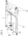
- the topographic printer or marking system of Figure 1 is a real size topographic printer for a building ( Figure 1 ) that comprises a rigid and non-deformable braced frame (1) made of light alloys, an autonomous movable system (2) (wheels or rollers or caterpillars) allowing the movement of the marking system over the entire surface to treat or to mark, an internal displacement device (3) enabling a movement in two directions (X and Y) for the printer head (4), a printer head (4) composed of a sprayer (5) for a narrow paint or liquid band that can be burnt, and an engraving laser (6). On the printer head (4) a prism support and topography prism (7) are placed.
- a box (8) that contains the electronic cards, battery, communication system and spraying paint stock reserve.
- two motorised hovercraft turbines help to raise the rear of the frame. They are in rotational movement when the device advances. Once the device is in place over the to-be printed area, they stop and the frame is posed on its legs (10).
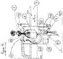
- the printing head ( Figure 2 ) is composed of a sprayer for narrow paint or liquid band that can be burnt and an engraving laser (6).
- a prism support and a topographic prism (7) are mounted on the Printing head.
- a Servo motor (11) permits to trigger or halt the spraying system giving way to the laser engraving system. It operates by rotation on the pivot (12).
- the system is guided by the topographic total station. To do so, once substantially correctly positioned, the device will displace the printer head to the four extreme corners of the rectangular printable area.
- the software will compare the readings measured by the topographic total station and the coordinates X, Y measured from the displaced printer head.
- the software calculates the change from the coordinates using the Helmert Transformation Method. Then it sends a G-code file (Tracing file) to the printer.
- the invented topography printer (called hereafter «Robot Topo») is intended to help and improve tracing steps of a topographic surveyor and the ⁇ Tracing>> workers by printing the complete plan on a slab to a real scale 1/1. It allows a direct link of the computerised plan or model of the BIM (Building Information Model) to its layout on the casted slab. To do so the drawing software breaks down the tracing zone in rectangular areas with a size corresponding to the printing size of the printer. The printer traces marks within a rectangular zone. Then it moves automatically to the next.
- «Robot Topo is intended to help and improve tracing steps of a topographic surveyor and the ⁇ Tracing>> workers by printing the complete plan on a slab to a real scale 1/1. It allows a direct link of the computerised plan or model of the BIM (Building Information Model) to its layout on the casted slab. To do so the drawing software breaks down the tracing zone in rectangular areas with a size corresponding to the printing size of
- the whole topography station measures and calculates in real time the 3D position of the robot's prism.
- a computer receives the position and guides the robot in an autonomous way on the site.
- the high precision laser tracer helps print the construction plan given by computer aided design software (CAO) directly to a scale of 1/1 onto the freshly laid concrete slab.
- CAO computer aided design software
- a remote operator commands the « Robot Topo » either from the working site or from its office.
- This office can be situated anywhere.
- the « Robot Topo » can work 24hours on 24hours, 7days on 7, with reloading phases (short or in continuous with a marking step) for material (Paint) and Energy (Electricity).
- the remote operator loads the actual current plan on the computer (in DWG, DNG format from computer-aided design software (CAD)) or from a file format IFC from the BIM server (Building Information Model) for the floor being built. Adjustment to the quotation, texts, customized notations, parameters is done to extract the plan for the 1/1 scale.
- Robot Topo » is put on a support placed on the freshly cast concrete slab (Parking).
- the « Robot Topo » is not put to use till the concrete has set to allow smooth displacement without any blocking risk (concrete sufficiently hardened for enabling movement of the wheels or caterpillars of the system of the invention on the cast concrete).
- the tracing/marking software extracts the relevant file containing all information of the rectangular zone located under the mobile part of the « Robot Topo Song
- the software generates then an instruction file, for example in the GCODE format (G-code), which is transmitted to the marking system.
- G-code GCODE format
- the « Robot Topo » makes a first move by depositing a colour jet and a second move with the laser tracer/marker.
- the text, metric information, lines, points; symbols are all traced/marked to the highest precision on the fresh slab (not fully hardened).
- the topographic printer controlling software can also do part of remote operator's job thus allowing him to carry out remote work at the same time on other construction sites.
- the remote operator benefits a complete training and can work from a remote office, whereby the operator can be a physically challenged person, enabling then his better integration in a working sector considered as physically requiring.
- the printing device can be used to print on vertical elements and also under horizontal elements (example ceilings). In such a case an operator must manually place the printer device, maintain its place and move it from one zone to another.
- the prism can be replaced by a series of integrated signal receptors GNSS RTK that calculates in real time the printer head position.
- the printer of the invention as shown in Figure 3 comprises a system (E) for real size topography printing on the surface of a construction site, said system (E) having at least (a) an non deformable mobile frame (1), (b) a displacement system (2) for moving the frame with respect to the site considered, (c) a marking system with a topographic prism, (d) a support (20) for the movable marking system with respect to the frame in at least two perpendicular directions (X, Y), in which this marking system (6) comprises of at least a spraying device (5) for spraying a liquid or paint band able to be burnt, and a engraving laser (6) for submitting a portion of the sprayed band (on the site surface) by the spraying device (5) to a burning step.
- this marking system (6) comprises of at least a spraying device (5) for spraying a liquid or paint band able to be burnt, and a engraving laser (6) for submitting a portion of the sprayed band (on the site surface) by the
- the displacement system 2 of the frame 1 comprises of at least an electric motor, while the means for moving the support 20 also has at least one electric motor (2A, 2B for example for the front end wheels).
- the system has at least one electric battery (11), advantageously of the rechargeable type, to supply the above mentioned electric motors 2A, 2B of the displacement system 2 of the frame 1 and of the support 20, the latter being moved by a motor 3A for moving the rail 3 in the direction Y and by a motor 3B for moving the support 20 along the rail 3 in the direction X.
- the system E comprises an electronic command system 12 ( electrically supplied by battery 11) to command different functions of the electronic system (12) that is associated with wireless communication means (for facilitating its working as an autonomous robot), to receive information at least with respect to the position of the system (E) on the construction site considered.
- an electronic command system 12 electrically supplied by battery 11
- wireless communication means for facilitating its working as an autonomous robot
- the spraying device 5 comprises a spraying head adapted for spraying on the construction site surface a paint band with width less than 5cm, advantageously comprised between 0.5cm and 2cm, while the engraving laser has a engraving head to mark on the band, points or lines with a thickness size of less than 3mm, advantageously from 0.1mm to 0.8mm.
- the electronic command system 12 is programmed to prevent the engraving laser 6 and the spraying device 5 to function during displacement of the non-deformable mobile frame 1 (so during the driving of the motor 2A and 2B) and to prevent the graving/marking by the engraving laser 6 during the functioning of the spraying device 5, whereby ensuring assure a certain time period between the spraying step and the laser engraving/marking, so as to ensure some drying/curing of the paint or resin prior its burning by the laser.
- the laser marking step after some drying of the sprayed paint or resin band ensures an increased and fast adhesive zone for at least a portion of the sprayed paint band. This is useful when the concrete slab is submitted to bad weather conditions.
- the displacement system at the rear end of the frame 1 has one wheel 21 pivoting around a vertical axis V, so its orientation being controlled by the motor 2C. This enables a better control of the direction of the movement of the frame from a marked zone towards an adjacent zone to be marked.
- each wheel At the front end of the frame 1 two wheels form the displacement system 2, said wheels pivoting also around vertical axes V.
- These two wheels are motorised, i.e. meaning that they are each associated to motors 2A and 2B respectively.
- the orientation of each wheel is controlled by motor 2C.
- Each wheel may have a different orientation compared to the other.
- the system E comprises a series of security means that sends electronic command signals for preventing or stopping the functioning of engraving laser (6) and advantageously also of the spraying device, when a security means detects a potential or real danger.
- the security means are advantageously selected from the group consisting of:
- the frame 1 is advantageously mounted on positioning means (like lift cylinders) to ensure that the frame 1 is stable in the desired plan (for example horizontal plan, or a plan parallel to the plan of the concrete slab).
- positioning means like lift cylinders
- the marking support system (20) is mounted to be mobile on the frame at least in two perpendicular directions (X, Y) in the manner to cover a marking zone, at least rectangular with one or more sides of at least 0.2m, advantageously at least 1.5m, the marking zone covering a surface of at least 0.4m 2 , advantageously at least 1m 2 , preferably comprised between 1 and 2m 2 .
- the marking support (20) comprises of a positioning camera that can be the camera 101, said camera being then also able to detect angles or crosses formed by lines previously marked by the laser, during a scanning step of the support 20 in the two directions X, Y.
- the displacement system of the frame 1 comprises at least a series of wheels or caterpillars each one driven by an electric motor.
- the wheels for example are situated on the same side as the platform Ibis intended to support the paint reservoir 200 and the pump 201 to feed (via one or more tubes or pipes ) the paint to be sprayed to the spraying head 5.
- the platform IBis can accommodate several paint reservoirs to make bands with different colours.
- the marking device support 20 is mounted to be mobile in translation along a first direction X on a rail, the latter being mounted to be mobile in translation with respect to the frame along a second direction Y perpendicular to the first direction X.
- the marking device support 20 comprises a carriage mounted mobile on the rail 3 that defines a vertical plan VI (symmetric plan of the rail) when the frame 1 is substantially horizontal, the carriage 20 having in relation to this vertical plan defined by the rail, on one side the engraving laser 6 with the overhanging topographic prism 7. Under the rail 3, and deported with respect to the laser 6, sits the spraying head 5.
- the offset values with respect to axes X and Y are approximately known during the conception of the system.
- the exact offset values between the prism position, the engraving laser and the spraying head are precisely recalculated during the calibration process.
- This calibration step is done by printing a same pattern in a same zone, after turning the frame 1 by about 180 degrees around the vertical axis.
- the topographic station helps in correct repositioning of the tracing pattern, the calibration is done by measuring the error as per X and Y. The correction to be made corresponds to half the distance in X and Y separating the patterns traced on the same position.
- the engraving laser 6 comprises a guiding laser beam tube 60 towards the site surface S.
- This tube is advantageously made of a material absorbing laser ray in case of reflection on the surface to trace.
- the support 20 is equipped with two distance laser detectors 102 (at least one detector) that enable to scan a horizontal area for existing obstacles around the tracing zone. This distance reading is recalculated in the general coordinate system by using the prism position.
- the frame 1 carries or is associated along one of its edges to a structure (platform Ibis) associated to at least one liquid or paint reservoir (200) (liquid or paint suitable to be burnt), and advantageously at least the battery or batteries (11) for supplying electric current to the electric motors and the pump (201), so as to deport the centre of gravity of the system towards the said edge, which is advantageously associated to a first wheel or caterpillar driven in movement by a first electric motor and a second wheel or caterpillar driven in movement by a second electric motor, the first wheel or caterpillar being distant from the second wheel or caterpillar.
- a structure platform Ibis
- the battery or batteries (11) for supplying electric current to the electric motors and the pump (201), so as to deport the centre of gravity of the system towards the said edge, which is advantageously associated to a first wheel or caterpillar driven in movement by a first electric motor and a second wheel or caterpillar driven in movement by a second electric motor, the first wheel or caterpillar being distant from the second wheel or caterpillar.
- This invention relates also to the use of a system according to the invention for topographic printing in real size on a surface of a building construction site, in which successive portions (S1,S2,S3, etc.) of the surface are each first printed with one or more paint bands or marking bands, followed with laser marking on one or more of said paint bands or marking bands.
- successive portions S1,S2,S3, etc.
- laser marking on one or more of said paint bands or marking bands.
- R1, R2, etc. laser reference marks
- This invention is also capable of repositioning itself onto a previous tracing comprising of minimum intersecting lines, even if said lines were not traced for the purpose of further repositioning.
- This means that the positioning camera is capable to recognise a previously marked zone for its precise repositioning. This case is useful when it is necessary to complete/correct a prior trace or marking. Indeed, the BIM is continuously amended with the project and the marking have to be amended or completed.
- the topographic printer as per the invention shown in figure 5 is a system (E) of a real size topographic printer on a site surface, where the system (E) comprises at least (a) an non deformable movable frame (1), (b) a displacement system (2) of the frame relative to the respective site, (c) a marking system with a topographic prism , (d) a support (20) for a marking system movable relative to the frame at least in two perpendicular directions (X,Y), in which the marking system comprises at least a spraying device (5) of a band of a paint or liquid suitable to be burnt and an engraving laser (6) for submitting a portion of the sprayed band (on the site by the spraying device) to a burning step.
- the marking system comprises at least a spraying device (5) of a band of a paint or liquid suitable to be burnt and an engraving laser (6) for submitting a portion of the sprayed band (on the site by the spraying device) to a burning step.
- a displacement rail (3) for support (20) fixed to a rotation system (300) has the advantage to allow the support to move all around the non-deformable frame, enabling to trace or mark in difficult or less-accessible zones and in the four sides of the frame.
Landscapes
- Engineering & Computer Science (AREA)
- Mechanical Engineering (AREA)
- Architecture (AREA)
- Robotics (AREA)
- Civil Engineering (AREA)
- Structural Engineering (AREA)
- Educational Administration (AREA)
- Physics & Mathematics (AREA)
- Business, Economics & Management (AREA)
- Educational Technology (AREA)
- General Physics & Mathematics (AREA)
- Theoretical Computer Science (AREA)
- Chemical & Material Sciences (AREA)
- Manufacturing & Machinery (AREA)
- Materials Engineering (AREA)
- Road Repair (AREA)
- Conveying And Assembling Of Building Elements In Situ (AREA)
- Manipulator (AREA)
- Spray Control Apparatus (AREA)
Applications Claiming Priority (2)
| Application Number | Priority Date | Filing Date | Title |
|---|---|---|---|
| BE2018/0094A BE1026046B1 (fr) | 2018-08-29 | 2018-08-29 | Imprimante de topographie en taille réelle pour le bâtiment |
| PCT/IB2019/055982 WO2020044138A1 (en) | 2018-08-29 | 2019-07-12 | Real size topography marking system |
Publications (2)
| Publication Number | Publication Date |
|---|---|
| EP3844355A1 EP3844355A1 (en) | 2021-07-07 |
| EP3844355B1 true EP3844355B1 (en) | 2022-12-14 |
Family
ID=63586632
Family Applications (1)
| Application Number | Title | Priority Date | Filing Date |
|---|---|---|---|
| EP19749425.5A Active EP3844355B1 (en) | 2018-08-29 | 2019-07-12 | Real size topography marking system |
Country Status (9)
| Country | Link |
|---|---|
| US (1) | US12116790B2 (da) |
| EP (1) | EP3844355B1 (da) |
| JP (1) | JP7315660B2 (da) |
| AU (1) | AU2019327202A1 (da) |
| BE (1) | BE1026046B1 (da) |
| CA (1) | CA3146056A1 (da) |
| DK (1) | DK3844355T3 (da) |
| MA (1) | MA53475A (da) |
| WO (1) | WO2020044138A1 (da) |
Families Citing this family (19)
| Publication number | Priority date | Publication date | Assignee | Title |
|---|---|---|---|---|
| CN111457202B (zh) * | 2020-04-01 | 2021-09-21 | 深圳市赛野展览展示有限公司 | 一种场景化互动展示系统和展示方法 |
| JP7456845B2 (ja) * | 2020-05-13 | 2024-03-27 | 株式会社竹中工務店 | 作業位置解析装置 |
| CN112268199B (zh) * | 2020-09-27 | 2022-07-19 | 北京灵境世界科技有限公司 | 一种多项数据采集车 |
| CN112916343B (zh) * | 2021-02-24 | 2021-11-02 | 赣州逸豪新材料股份有限公司 | 一种铝基板加工用定向涂胶装置及其加工方法 |
| JP7687117B2 (ja) * | 2021-07-30 | 2025-06-03 | セイコーエプソン株式会社 | ロボットシステムの制御方法およびロボットシステム |
| CN114459442B (zh) * | 2022-02-14 | 2024-03-12 | 何丽 | 一种水利工程建设管理用智能测量装置 |
| CN114658237A (zh) * | 2022-03-22 | 2022-06-24 | 江西旅游商贸职业学院 | 一种吊顶定位铺设用辅助装置 |
| CN114837441B (zh) * | 2022-05-27 | 2023-05-23 | 江西建邦装配式建筑有限公司 | 一种装配式建筑用墙体定位装置 |
| CN114991500B (zh) * | 2022-06-21 | 2023-05-23 | 江西建邦装配式建筑有限公司 | 一种多高层钢结构建筑辅助安装设备 |
| CN115007367A (zh) * | 2022-07-15 | 2022-09-06 | 上海联影智能医疗科技有限公司 | 一种喷涂方法和系统 |
| ES2962583A1 (es) * | 2022-08-19 | 2024-03-19 | Phenomenon Robotics S L | Robot trazador de lineas de marcaje para construccion |
| CN115451926B (zh) * | 2022-11-04 | 2023-01-31 | 河北省地质矿产勘查开发局国土资源勘查中心(河北省矿山和地质灾害应急救援中心) | 一种用于地质勘测的标记装置 |
| BE1030598B1 (fr) | 2022-12-14 | 2024-01-09 | Viage SPRL | Système automatique de marquage topographique en sous face et en vertical |
| BE1031003B1 (fr) * | 2023-03-13 | 2024-05-27 | DE SELSATEN Vincent AGIE | Pistolet topographique d'impression manuel de marquage de niveaux et de repères |
| CN116654776A (zh) * | 2023-03-14 | 2023-08-29 | 浙江省三建建设集团有限公司 | 一种基于bim系统的幕墙轨道吊装定位装置及其使用方法 |
| CN116787392A (zh) * | 2023-06-26 | 2023-09-22 | 中铁南方工程装备有限公司 | 一种用于任意厚度板件的横纵基准线快速返线尺 |
| CN117569623B (zh) * | 2023-12-07 | 2026-01-27 | 中国水利水电第三工程局有限公司 | 一种钢结构混凝土楼板钢筋定位半自动画线装置 |
| CN118149781B (zh) * | 2024-05-09 | 2024-07-09 | 招金有色矿业有限公司 | 一种地质剖面厚度测量装置 |
| CN118590624B (zh) * | 2024-08-06 | 2024-10-11 | 四川智浩工程技术有限公司 | 一种工程施工现场风险区域管控系统 |
Family Cites Families (24)
| Publication number | Priority date | Publication date | Assignee | Title |
|---|---|---|---|---|
| JP2599879B2 (ja) * | 1993-03-08 | 1997-04-16 | 鹿島建設株式会社 | 自動墨出し方法 |
| JP3088612B2 (ja) * | 1994-07-12 | 2000-09-18 | 株式会社熊谷組 | 墨出し装置 |
| US5453931A (en) * | 1994-10-25 | 1995-09-26 | Watts, Jr.; James R. | Navigating robot with reference line plotter |
| US5755072A (en) * | 1996-05-13 | 1998-05-26 | Lingafelter; Kenneth | Construction method |
| US6007929A (en) * | 1997-02-20 | 1999-12-28 | Infosight Corporation | Dual paint coat laser-marking labeling system, method and product |
| US7181887B1 (en) * | 2000-03-24 | 2007-02-27 | Fred Christian Baij | Framing lumber products and methods |
| US20080010910A1 (en) * | 2000-03-24 | 2008-01-17 | Baij Fred C | Framing lumber product and a bundle of pre-marked framing lumber products |
| JP2001289638A (ja) * | 2000-04-11 | 2001-10-19 | Sumitomo Densetsu Corp | 自走式作業装置 |
| DE10034035C2 (de) * | 2000-07-13 | 2002-10-31 | Hilti Ag | Markiervorrichtung und Verfahren zum visuellen Fixieren von Signalmarkierungen an vermessenen Flächen |
| US10215562B2 (en) * | 2004-07-16 | 2019-02-26 | Invention Science Find I, LLC | Personalized prototyping |
| JP2007118165A (ja) | 2005-10-31 | 2007-05-17 | Hitachi Plant Technologies Ltd | 墨位置記録装置 |
| US7621053B2 (en) * | 2007-04-13 | 2009-11-24 | Virtek Vision International Inc. | Assembly apparatus |
| US20090277031A1 (en) * | 2008-05-06 | 2009-11-12 | Full Scale Layouts, Inc. | Construction layout method and template |
| DE102010026102B4 (de) * | 2010-07-05 | 2016-10-06 | Audi Ag | Verfahren zur Aufzeichnung von Aufbaumarkierungen für eine Fertigungsanlage, insbesondere im Fahrzeugbau |
| US8087179B1 (en) * | 2010-07-12 | 2012-01-03 | Aldo Gomez | Plan orientation template |
| US8533927B2 (en) * | 2010-10-14 | 2013-09-17 | Freeman Capital Company | Full-scale architectural template and method for installing construction elements for exhibitions, trade shows, conventions and events without damaging carpet or floor |
| US20130255056A1 (en) * | 2010-10-14 | 2013-10-03 | Freeman Capital Company | Full-scale architectural template and method for installing construction elements for exhibitions, trade shows, conventions and events |
| EP3176542A1 (en) * | 2015-12-01 | 2017-06-07 | Beamrider Limited | Odometer for a vehicle |
| EP3374934A1 (en) | 2015-12-01 | 2018-09-19 | Vinci Construction | Method and system for assisting installation of elements in a construction work |
| US11041304B2 (en) * | 2018-09-06 | 2021-06-22 | Michael Schettine | Interface strips for structural framing and related framing methods |
| JP7527663B2 (ja) | 2019-04-23 | 2024-08-05 | ダスティ ロボティックス インコーポレイテッド | ライン印刷経路最適化を伴う自走式印刷ロボット及び印刷方法 |
| US11383276B2 (en) * | 2019-09-13 | 2022-07-12 | Rdbj, Llc | Lumber use designation system and method |
| US11767669B2 (en) * | 2020-02-25 | 2023-09-26 | Patrick Churchman | System and method of installing system of sheets of sheathing having laser engraved and/or rasterbated image of building information |
| US20220404818A1 (en) * | 2021-02-26 | 2022-12-22 | Ball Corporation | Apparatus and method of engraving machine readable information on a metallic workpiece during manufacturing and tracking systems related thereto |
-
2018
- 2018-08-29 BE BE2018/0094A patent/BE1026046B1/fr not_active IP Right Cessation
-
2019
- 2019-07-12 AU AU2019327202A patent/AU2019327202A1/en not_active Abandoned
- 2019-07-12 JP JP2021510863A patent/JP7315660B2/ja active Active
- 2019-07-12 EP EP19749425.5A patent/EP3844355B1/en active Active
- 2019-07-12 MA MA053475A patent/MA53475A/fr unknown
- 2019-07-12 DK DK19749425.5T patent/DK3844355T3/da active
- 2019-07-12 WO PCT/IB2019/055982 patent/WO2020044138A1/en not_active Ceased
- 2019-07-12 CA CA3146056A patent/CA3146056A1/en active Pending
-
2021
- 2021-02-24 US US17/184,067 patent/US12116790B2/en active Active
Also Published As
| Publication number | Publication date |
|---|---|
| AU2019327202A1 (en) | 2021-03-18 |
| WO2020044138A1 (en) | 2020-03-05 |
| JP7315660B2 (ja) | 2023-07-26 |
| MA53475A (fr) | 2021-12-08 |
| EP3844355A1 (en) | 2021-07-07 |
| US20210180346A1 (en) | 2021-06-17 |
| DK3844355T3 (da) | 2023-03-20 |
| BE1026046B1 (fr) | 2019-09-24 |
| CA3146056A1 (en) | 2020-03-05 |
| US12116790B2 (en) | 2024-10-15 |
| JP2022511283A (ja) | 2022-01-31 |
Similar Documents
| Publication | Publication Date | Title |
|---|---|---|
| EP3844355B1 (en) | Real size topography marking system | |
| EP2618941B1 (en) | Surface spattering device | |
| CN104129173B (zh) | 图形施加系统 | |
| JP2001289638A (ja) | 自走式作業装置 | |
| US20220083705A1 (en) | System and method for automated layout of buildings | |
| BR102013005874A2 (pt) | Sistema de aplicação gráfica | |
| KR101071109B1 (ko) | 벽 등반 인쇄 방법 및 시스템 | |
| US20130310971A1 (en) | Robotic Construction Site Marking Apparatus | |
| CN114147723B (zh) | 一种自动放样机器人系统及其运行方法 | |
| JP6795741B2 (ja) | 天井面への自動墨出し方法と自動墨出し用無人飛翔体 | |
| CN119773363B (zh) | 一种移动机器人打印作业方法 | |
| KR20090038619A (ko) | 고소작업차량의 작업대 자동거리 조절장치 | |
| JP2007118165A (ja) | 墨位置記録装置 | |
| EP3195110A1 (en) | Method of marking outline of large scale graphic element and robot for such method | |
| JPH06220987A (ja) | 天井工事用ロボット装置 | |
| EP4610432A1 (en) | Deployment machine, welding machine, equipment and method for the automated installation of geomembranes | |
| JPH06137868A (ja) | 既設建物外壁形状寸法測定方法及び測距装置 | |
| JP2025133344A (ja) | 自走式道路路面標示文字描画車両 | |
| JPH0843073A (ja) | 構造物の3次元計測装置 | |
| JPH0843008A (ja) | 構造物の3次元計測装置 | |
| WO2015115910A1 (en) | A system and a method for positioning and placing of blocks in a ship's dock | |
| CN117091548A (zh) | 一种基于bim的爬壁机器人房间检测系统及方法 |
Legal Events
| Date | Code | Title | Description |
|---|---|---|---|
| STAA | Information on the status of an ep patent application or granted ep patent |
Free format text: STATUS: UNKNOWN |
|
| STAA | Information on the status of an ep patent application or granted ep patent |
Free format text: STATUS: THE INTERNATIONAL PUBLICATION HAS BEEN MADE |
|
| STAA | Information on the status of an ep patent application or granted ep patent |
Free format text: STATUS: REQUEST FOR EXAMINATION WAS MADE |
|
| PUAI | Public reference made under article 153(3) epc to a published international application that has entered the european phase |
Free format text: ORIGINAL CODE: 0009012 |
|
| 17P | Request for examination filed |
Effective date: 20210203 |
|
| AK | Designated contracting states |
Kind code of ref document: A1 Designated state(s): AL AT BE BG CH CY CZ DE DK EE ES FI FR GB GR HR HU IE IS IT LI LT LU LV MC MK MT NL NO PL PT RO RS SE SI SK SM TR |
|
| DAX | Request for extension of the european patent (deleted) | ||
| RAV | Requested validation state of the european patent: fee paid |
Extension state: TN Effective date: 20210122 Extension state: MA Effective date: 20210122 |
|
| GRAP | Despatch of communication of intention to grant a patent |
Free format text: ORIGINAL CODE: EPIDOSNIGR1 |
|
| STAA | Information on the status of an ep patent application or granted ep patent |
Free format text: STATUS: GRANT OF PATENT IS INTENDED |
|
| INTG | Intention to grant announced |
Effective date: 20220701 |
|
| GRAS | Grant fee paid |
Free format text: ORIGINAL CODE: EPIDOSNIGR3 |
|
| GRAA | (expected) grant |
Free format text: ORIGINAL CODE: 0009210 |
|
| STAA | Information on the status of an ep patent application or granted ep patent |
Free format text: STATUS: THE PATENT HAS BEEN GRANTED |
|
| AK | Designated contracting states |
Kind code of ref document: B1 Designated state(s): AL AT BE BG CH CY CZ DE DK EE ES FI FR GB GR HR HU IE IS IT LI LT LU LV MC MK MT NL NO PL PT RO RS SE SI SK SM TR |
|
| REG | Reference to a national code |
Ref country code: GB Ref legal event code: FG4D |
|
| REG | Reference to a national code |
Ref country code: CH Ref legal event code: EP |
|
| REG | Reference to a national code |
Ref country code: IE Ref legal event code: FG4D |
|
| REG | Reference to a national code |
Ref country code: DE Ref legal event code: R096 Ref document number: 602019023193 Country of ref document: DE |
|
| REG | Reference to a national code |
Ref country code: AT Ref legal event code: REF Ref document number: 1537737 Country of ref document: AT Kind code of ref document: T Effective date: 20230115 |
|
| REG | Reference to a national code |
Ref country code: NL Ref legal event code: FP |
|
| REG | Reference to a national code |
Ref country code: DK Ref legal event code: T3 Effective date: 20230314 |
|
| REG | Reference to a national code |
Ref country code: LT Ref legal event code: MG9D |
|
| PG25 | Lapsed in a contracting state [announced via postgrant information from national office to epo] |
Ref country code: SE Free format text: LAPSE BECAUSE OF FAILURE TO SUBMIT A TRANSLATION OF THE DESCRIPTION OR TO PAY THE FEE WITHIN THE PRESCRIBED TIME-LIMIT Effective date: 20221214 Ref country code: NO Free format text: LAPSE BECAUSE OF FAILURE TO SUBMIT A TRANSLATION OF THE DESCRIPTION OR TO PAY THE FEE WITHIN THE PRESCRIBED TIME-LIMIT Effective date: 20230314 Ref country code: LT Free format text: LAPSE BECAUSE OF FAILURE TO SUBMIT A TRANSLATION OF THE DESCRIPTION OR TO PAY THE FEE WITHIN THE PRESCRIBED TIME-LIMIT Effective date: 20221214 Ref country code: FI Free format text: LAPSE BECAUSE OF FAILURE TO SUBMIT A TRANSLATION OF THE DESCRIPTION OR TO PAY THE FEE WITHIN THE PRESCRIBED TIME-LIMIT Effective date: 20221214 |
|
| REG | Reference to a national code |
Ref country code: AT Ref legal event code: MK05 Ref document number: 1537737 Country of ref document: AT Kind code of ref document: T Effective date: 20221214 |
|
| PG25 | Lapsed in a contracting state [announced via postgrant information from national office to epo] |
Ref country code: RS Free format text: LAPSE BECAUSE OF FAILURE TO SUBMIT A TRANSLATION OF THE DESCRIPTION OR TO PAY THE FEE WITHIN THE PRESCRIBED TIME-LIMIT Effective date: 20221214 Ref country code: LV Free format text: LAPSE BECAUSE OF FAILURE TO SUBMIT A TRANSLATION OF THE DESCRIPTION OR TO PAY THE FEE WITHIN THE PRESCRIBED TIME-LIMIT Effective date: 20221214 Ref country code: HR Free format text: LAPSE BECAUSE OF FAILURE TO SUBMIT A TRANSLATION OF THE DESCRIPTION OR TO PAY THE FEE WITHIN THE PRESCRIBED TIME-LIMIT Effective date: 20221214 Ref country code: GR Free format text: LAPSE BECAUSE OF FAILURE TO SUBMIT A TRANSLATION OF THE DESCRIPTION OR TO PAY THE FEE WITHIN THE PRESCRIBED TIME-LIMIT Effective date: 20230315 |
|
| PG25 | Lapsed in a contracting state [announced via postgrant information from national office to epo] |
Ref country code: SM Free format text: LAPSE BECAUSE OF FAILURE TO SUBMIT A TRANSLATION OF THE DESCRIPTION OR TO PAY THE FEE WITHIN THE PRESCRIBED TIME-LIMIT Effective date: 20221214 Ref country code: RO Free format text: LAPSE BECAUSE OF FAILURE TO SUBMIT A TRANSLATION OF THE DESCRIPTION OR TO PAY THE FEE WITHIN THE PRESCRIBED TIME-LIMIT Effective date: 20221214 Ref country code: PT Free format text: LAPSE BECAUSE OF FAILURE TO SUBMIT A TRANSLATION OF THE DESCRIPTION OR TO PAY THE FEE WITHIN THE PRESCRIBED TIME-LIMIT Effective date: 20230414 Ref country code: ES Free format text: LAPSE BECAUSE OF FAILURE TO SUBMIT A TRANSLATION OF THE DESCRIPTION OR TO PAY THE FEE WITHIN THE PRESCRIBED TIME-LIMIT Effective date: 20221214 Ref country code: EE Free format text: LAPSE BECAUSE OF FAILURE TO SUBMIT A TRANSLATION OF THE DESCRIPTION OR TO PAY THE FEE WITHIN THE PRESCRIBED TIME-LIMIT Effective date: 20221214 Ref country code: CZ Free format text: LAPSE BECAUSE OF FAILURE TO SUBMIT A TRANSLATION OF THE DESCRIPTION OR TO PAY THE FEE WITHIN THE PRESCRIBED TIME-LIMIT Effective date: 20221214 Ref country code: AT Free format text: LAPSE BECAUSE OF FAILURE TO SUBMIT A TRANSLATION OF THE DESCRIPTION OR TO PAY THE FEE WITHIN THE PRESCRIBED TIME-LIMIT Effective date: 20221214 |
|
| PG25 | Lapsed in a contracting state [announced via postgrant information from national office to epo] |
Ref country code: SK Free format text: LAPSE BECAUSE OF FAILURE TO SUBMIT A TRANSLATION OF THE DESCRIPTION OR TO PAY THE FEE WITHIN THE PRESCRIBED TIME-LIMIT Effective date: 20221214 Ref country code: PL Free format text: LAPSE BECAUSE OF FAILURE TO SUBMIT A TRANSLATION OF THE DESCRIPTION OR TO PAY THE FEE WITHIN THE PRESCRIBED TIME-LIMIT Effective date: 20221214 Ref country code: IS Free format text: LAPSE BECAUSE OF FAILURE TO SUBMIT A TRANSLATION OF THE DESCRIPTION OR TO PAY THE FEE WITHIN THE PRESCRIBED TIME-LIMIT Effective date: 20230414 Ref country code: AL Free format text: LAPSE BECAUSE OF FAILURE TO SUBMIT A TRANSLATION OF THE DESCRIPTION OR TO PAY THE FEE WITHIN THE PRESCRIBED TIME-LIMIT Effective date: 20221214 |
|
| REG | Reference to a national code |
Ref country code: DE Ref legal event code: R097 Ref document number: 602019023193 Country of ref document: DE |
|
| PLBE | No opposition filed within time limit |
Free format text: ORIGINAL CODE: 0009261 |
|
| STAA | Information on the status of an ep patent application or granted ep patent |
Free format text: STATUS: NO OPPOSITION FILED WITHIN TIME LIMIT |
|
| 26N | No opposition filed |
Effective date: 20230915 |
|
| PG25 | Lapsed in a contracting state [announced via postgrant information from national office to epo] |
Ref country code: SI Free format text: LAPSE BECAUSE OF FAILURE TO SUBMIT A TRANSLATION OF THE DESCRIPTION OR TO PAY THE FEE WITHIN THE PRESCRIBED TIME-LIMIT Effective date: 20221214 |
|
| PG25 | Lapsed in a contracting state [announced via postgrant information from national office to epo] |
Ref country code: MC Free format text: LAPSE BECAUSE OF FAILURE TO SUBMIT A TRANSLATION OF THE DESCRIPTION OR TO PAY THE FEE WITHIN THE PRESCRIBED TIME-LIMIT Effective date: 20221214 |
|
| PG25 | Lapsed in a contracting state [announced via postgrant information from national office to epo] |
Ref country code: MC Free format text: LAPSE BECAUSE OF FAILURE TO SUBMIT A TRANSLATION OF THE DESCRIPTION OR TO PAY THE FEE WITHIN THE PRESCRIBED TIME-LIMIT Effective date: 20221214 |
|
| PG25 | Lapsed in a contracting state [announced via postgrant information from national office to epo] |
Ref country code: LU Free format text: LAPSE BECAUSE OF NON-PAYMENT OF DUE FEES Effective date: 20230712 |
|
| PG25 | Lapsed in a contracting state [announced via postgrant information from national office to epo] |
Ref country code: LU Free format text: LAPSE BECAUSE OF NON-PAYMENT OF DUE FEES Effective date: 20230712 |
|
| PG25 | Lapsed in a contracting state [announced via postgrant information from national office to epo] |
Ref country code: IT Free format text: LAPSE BECAUSE OF FAILURE TO SUBMIT A TRANSLATION OF THE DESCRIPTION OR TO PAY THE FEE WITHIN THE PRESCRIBED TIME-LIMIT Effective date: 20221214 |
|
| PGFP | Annual fee paid to national office [announced via postgrant information from national office to epo] |
Ref country code: IE Payment date: 20240624 Year of fee payment: 6 |
|
| PG25 | Lapsed in a contracting state [announced via postgrant information from national office to epo] |
Ref country code: BG Free format text: LAPSE BECAUSE OF FAILURE TO SUBMIT A TRANSLATION OF THE DESCRIPTION OR TO PAY THE FEE WITHIN THE PRESCRIBED TIME-LIMIT Effective date: 20221214 |
|
| PG25 | Lapsed in a contracting state [announced via postgrant information from national office to epo] |
Ref country code: BG Free format text: LAPSE BECAUSE OF FAILURE TO SUBMIT A TRANSLATION OF THE DESCRIPTION OR TO PAY THE FEE WITHIN THE PRESCRIBED TIME-LIMIT Effective date: 20221214 |
|
| PG25 | Lapsed in a contracting state [announced via postgrant information from national office to epo] |
Ref country code: CY Free format text: LAPSE BECAUSE OF FAILURE TO SUBMIT A TRANSLATION OF THE DESCRIPTION OR TO PAY THE FEE WITHIN THE PRESCRIBED TIME-LIMIT; INVALID AB INITIO Effective date: 20190712 |
|
| PG25 | Lapsed in a contracting state [announced via postgrant information from national office to epo] |
Ref country code: HU Free format text: LAPSE BECAUSE OF FAILURE TO SUBMIT A TRANSLATION OF THE DESCRIPTION OR TO PAY THE FEE WITHIN THE PRESCRIBED TIME-LIMIT; INVALID AB INITIO Effective date: 20190712 |
|
| PGFP | Annual fee paid to national office [announced via postgrant information from national office to epo] |
Ref country code: NL Payment date: 20250701 Year of fee payment: 7 |
|
| PGFP | Annual fee paid to national office [announced via postgrant information from national office to epo] |
Ref country code: DK Payment date: 20250701 Year of fee payment: 7 Ref country code: DE Payment date: 20250701 Year of fee payment: 7 |
|
| PGFP | Annual fee paid to national office [announced via postgrant information from national office to epo] |
Ref country code: GB Payment date: 20250701 Year of fee payment: 7 Ref country code: BE Payment date: 20250701 Year of fee payment: 7 |
|
| PGFP | Annual fee paid to national office [announced via postgrant information from national office to epo] |
Ref country code: FR Payment date: 20250701 Year of fee payment: 7 |
|
| PGFP | Annual fee paid to national office [announced via postgrant information from national office to epo] |
Ref country code: CH Payment date: 20250801 Year of fee payment: 7 |
|
| VS25 | Lapsed in a validation state [announced via postgrant information from nat. office to epo] |
Ref country code: MA Free format text: FAILURE TO ELECT DOMICILE IN THE NATIONAL COUNTRY Effective date: 20230315 |
|
| PG25 | Lapsed in a contracting state [announced via postgrant information from national office to epo] |
Ref country code: TR Free format text: LAPSE BECAUSE OF FAILURE TO SUBMIT A TRANSLATION OF THE DESCRIPTION OR TO PAY THE FEE WITHIN THE PRESCRIBED TIME-LIMIT Effective date: 20221214 |