EP3844524B1 - Standortinformationsbestimmung basierend auf zeitmessungen in drahtlosen netzwerken - Google Patents
Standortinformationsbestimmung basierend auf zeitmessungen in drahtlosen netzwerken Download PDFInfo
- Publication number
- EP3844524B1 EP3844524B1 EP19855908.0A EP19855908A EP3844524B1 EP 3844524 B1 EP3844524 B1 EP 3844524B1 EP 19855908 A EP19855908 A EP 19855908A EP 3844524 B1 EP3844524 B1 EP 3844524B1
- Authority
- EP
- European Patent Office
- Prior art keywords
- timing
- network devices
- subset
- time
- request
- Prior art date
- Legal status (The legal status is an assumption and is not a legal conclusion. Google has not performed a legal analysis and makes no representation as to the accuracy of the status listed.)
- Active
Links
Images




Classifications
-
- H—ELECTRICITY
- H04—ELECTRIC COMMUNICATION TECHNIQUE
- H04W—WIRELESS COMMUNICATION NETWORKS
- H04W64/00—Locating users or terminals or network equipment for network management purposes, e.g. mobility management
-
- H—ELECTRICITY
- H04—ELECTRIC COMMUNICATION TECHNIQUE
- H04W—WIRELESS COMMUNICATION NETWORKS
- H04W64/00—Locating users or terminals or network equipment for network management purposes, e.g. mobility management
- H04W64/003—Locating users or terminals or network equipment for network management purposes, e.g. mobility management locating network equipment
-
- G—PHYSICS
- G01—MEASURING; TESTING
- G01S—RADIO DIRECTION-FINDING; RADIO NAVIGATION; DETERMINING DISTANCE OR VELOCITY BY USE OF RADIO WAVES; LOCATING OR PRESENCE-DETECTING BY USE OF THE REFLECTION OR RERADIATION OF RADIO WAVES; ANALOGOUS ARRANGEMENTS USING OTHER WAVES
- G01S3/00—Direction-finders for determining the direction from which infrasonic, sonic, ultrasonic or electromagnetic waves, or particle emission, not having a directional significance, are being received
- G01S3/02—Direction-finders for determining the direction from which infrasonic, sonic, ultrasonic or electromagnetic waves, or particle emission, not having a directional significance, are being received using radio waves
- G01S3/14—Systems for determining direction or deviation from predetermined direction
- G01S3/46—Systems for determining direction or deviation from predetermined direction using antennas spaced apart and measuring phase or time difference between signals therefrom, i.e. path-difference systems
- G01S3/50—Systems for determining direction or deviation from predetermined direction using antennas spaced apart and measuring phase or time difference between signals therefrom, i.e. path-difference systems the waves arriving at the antennas being pulse modulated and the time difference of their arrival being measured
-
- G—PHYSICS
- G01—MEASURING; TESTING
- G01S—RADIO DIRECTION-FINDING; RADIO NAVIGATION; DETERMINING DISTANCE OR VELOCITY BY USE OF RADIO WAVES; LOCATING OR PRESENCE-DETECTING BY USE OF THE REFLECTION OR RERADIATION OF RADIO WAVES; ANALOGOUS ARRANGEMENTS USING OTHER WAVES
- G01S5/00—Position-fixing by co-ordinating two or more direction or position line determinations; Position-fixing by co-ordinating two or more distance determinations
- G01S5/02—Position-fixing by co-ordinating two or more direction or position line determinations; Position-fixing by co-ordinating two or more distance determinations using radio waves
- G01S5/0205—Details
-
- G—PHYSICS
- G01—MEASURING; TESTING
- G01S—RADIO DIRECTION-FINDING; RADIO NAVIGATION; DETERMINING DISTANCE OR VELOCITY BY USE OF RADIO WAVES; LOCATING OR PRESENCE-DETECTING BY USE OF THE REFLECTION OR RERADIATION OF RADIO WAVES; ANALOGOUS ARRANGEMENTS USING OTHER WAVES
- G01S5/00—Position-fixing by co-ordinating two or more direction or position line determinations; Position-fixing by co-ordinating two or more distance determinations
- G01S5/02—Position-fixing by co-ordinating two or more direction or position line determinations; Position-fixing by co-ordinating two or more distance determinations using radio waves
- G01S5/14—Determining absolute distances from a plurality of spaced points of known location
-
- G—PHYSICS
- G01—MEASURING; TESTING
- G01S—RADIO DIRECTION-FINDING; RADIO NAVIGATION; DETERMINING DISTANCE OR VELOCITY BY USE OF RADIO WAVES; LOCATING OR PRESENCE-DETECTING BY USE OF THE REFLECTION OR RERADIATION OF RADIO WAVES; ANALOGOUS ARRANGEMENTS USING OTHER WAVES
- G01S7/00—Details of systems according to groups G01S13/00, G01S15/00, G01S17/00
- G01S7/48—Details of systems according to groups G01S13/00, G01S15/00, G01S17/00 of systems according to group G01S17/00
- G01S7/483—Details of pulse systems
- G01S7/486—Receivers
- G01S7/4865—Time delay measurement, e.g. time-of-flight measurement, time of arrival measurement or determining the exact position of a peak
-
- H—ELECTRICITY
- H04—ELECTRIC COMMUNICATION TECHNIQUE
- H04B—TRANSMISSION
- H04B17/00—Monitoring; Testing
- H04B17/30—Monitoring; Testing of propagation channels
- H04B17/309—Measuring or estimating channel quality parameters
- H04B17/364—Delay profiles
-
- H—ELECTRICITY
- H04—ELECTRIC COMMUNICATION TECHNIQUE
- H04J—MULTIPLEX COMMUNICATION
- H04J3/00—Time-division multiplex systems
- H04J3/02—Details
- H04J3/06—Synchronising arrangements
- H04J3/0635—Clock or time synchronisation in a network
- H04J3/0638—Clock or time synchronisation among nodes; Internode synchronisation
- H04J3/0658—Clock or time synchronisation among packet nodes
- H04J3/0661—Clock or time synchronisation among packet nodes using timestamps
- H04J3/0667—Bidirectional timestamps, e.g. NTP or PTP for compensation of clock drift and for compensation of propagation delays
-
- H—ELECTRICITY
- H04—ELECTRIC COMMUNICATION TECHNIQUE
- H04J—MULTIPLEX COMMUNICATION
- H04J1/00—Frequency-division multiplex systems
- H04J1/02—Details
- H04J1/06—Arrangements for supplying the carrier waves ; Arrangements for supplying synchronisation signals
-
- H—ELECTRICITY
- H04—ELECTRIC COMMUNICATION TECHNIQUE
- H04L—TRANSMISSION OF DIGITAL INFORMATION, e.g. TELEGRAPHIC COMMUNICATION
- H04L43/00—Arrangements for monitoring or testing data switching networks
- H04L43/08—Monitoring or testing based on specific metrics, e.g. QoS, energy consumption or environmental parameters
- H04L43/0852—Delays
- H04L43/0864—Round trip delays
-
- H—ELECTRICITY
- H04—ELECTRIC COMMUNICATION TECHNIQUE
- H04W—WIRELESS COMMUNICATION NETWORKS
- H04W84/00—Network topologies
- H04W84/02—Hierarchically pre-organised networks, e.g. paging networks, cellular networks, WLAN [Wireless Local Area Network] or WLL [Wireless Local Loop]
- H04W84/10—Small scale networks; Flat hierarchical networks
- H04W84/12—WLAN [Wireless Local Area Networks]
Definitions
- This document is directed generally to wireless communications.
- Wireless communication technologies are moving the world toward an increasingly connected and networked society.
- the rapid growth of wireless communications and advances in technology has led to greater demand for capacity and connectivity.
- Other aspects, such as energy consumption, device cost, spectral efficiency, and latency are also important to meeting the needs of various communication scenarios.
- next generation systems and wireless communication techniques need to provide support for an increased number of users and devices, as well as support for higher data rates, therein requiring improved location and measurement accuracy and efficiency.
- US 2014/0073352 A1 relates to methods for determining location of a device by exchanging a plurality of messages with one or more devices.
- CN 107 076 829 A relates to a procedure for determining distance (or angle) between a pair of electronic devices wirelessly connected to one another.
- US 2016/0037477 A1 relates to a station that receives a schedule from a reference device in a wireless network.
- This document relates to methods, systems, and devices for location information determination based on timing measurements, which enable a wireless station to determine its location when, for example, GPS is not available.
- a wireless communication method includes transmitting, by a communication apparatus, a timing request to a subset of a plurality of network devices, where the timing request comprises a respective expected response time for each of the subset of the plurality of network devices, receiving, at a plurality of times, a plurality of timing measurements from each of the subset of the plurality of network devices, where each of the plurality of times is based on the corresponding expected response time, and the plurality of timing measurements comprises a respective time of arrival (ToA) timestamp and a respective time of departure (ToD) timestamp, and determining a location information of the communication apparatus based on an estimate of a round trip delay that is computed using a difference of the respective ToA and ToD timestamps from the plurality of timing measurements.
- ToA time of arrival
- ToD time of departure
- a wireless communication method includes transmitting a plurality of initial timing requests to a plurality of network devices, receiving a plurality of initial timing responses from a subset of the plurality of network devices, transmitting a timing request to the subset of the plurality of network devices, where the timing request identifies transmission resources to be used by each of the subset of the plurality of network devices, receiving, over the respective transmission resources, a plurality of timing measurements from the subset of the plurality of network devices, where the plurality of timing measurements comprises a respective ToA timestamp and a respective ToD timestamp, and determining a location information of the apparatus based on an estimate of a round trip delay that is computed using a difference of the respective ToA and ToD timestamps from the plurality of timing measurements.
- a wireless communication method includes transmitting, to a group of network devices, a timing request soliciting time measurement responses, the timing request including information for receiving the time measurement responses in a collision-free manner, receiving, in the collision-free manner, the timing measurement responses from at least some network devices from the group, where each timing measurement response includes a first field indicative of a reception time at which a corresponding network device received the timing request and a second field indicative of response time at which the corresponding network device transmitted its timing measurement response, and determining a location of the communication apparatus based on the timing measurement responses.
- the above-described methods are embodied in the form of processor-executable code and stored in a computer-readable program medium.
- a device that is configured or operable to perform the above-described methods is disclosed.
- Wireless communication systems can include a network of one or more access points (APs) to communicate with one or more wireless stations (STAs).
- An AP can emit radio signals that carry management information, control information or users' data to one or more wireless stations, and a station can also transmit radio signals to the access point in the same frequency channel via time division duplexing (TDD) or in a different frequency channel via frequency division duplexing (FDD).
- TDD time division duplexing
- FDD frequency division duplexing
- IEEE 802.11 is an asynchronous time division duplexing technology used by a wireless local area network (WLAN).
- WLAN wireless local area network
- the basic unit of WLAN is called a basic service set (BSS).
- An infrastructure BSS is the BSS with stations that communicate through associating with an Access Point (AP) to connect to the wired network or Internet.
- AP Access Point
- both access point and stations share the same frequency channel via using Carrier Sensing Multiple Access with Collision Avoidance (CSMA/CA) technology, a kind of TDD mechanism, for multiple access and data transmission.
- CSMA/CA Carrier Sensing Multiple Access with Collision Avoidance
- the Global Positioning System is a widely used positioning mechanism in wireless communication systems and consumer products. To get the geo-positioning information, the GPS receiver receives signals from at least four GPS satellites. This GPS mechanism may work well in outdoor cases, but not well for indoor environments as the signals from GPS satellites are too weak to penetrate indoors for the GPS receiver to acquire and synchronize with. Therefore, it is beneficial to have geo-positioning mechanisms other than GPS for indoor and/or outdoor environment.
- Typical geo-positioning mechanisms for the indoor environment include Wi-Fi-based received signal strength indication (RSSI) measurements and Time of Arrival (ToA) measurements.
- RSSI received signal strength indication
- ToA Time of Arrival
- the RSSI-based method leverages the characteristics of radio signal transmission decay as travelling, and uses the measured RSSI to derive the distance between the transmitter and receiver.
- ToA-based methods rely on the timing measurement from the initiating station transmitting the measurement signal to receiving the response signal sent from the responding station. Due to space limitations in an indoor environment, the timing measurement method should be very precise, otherwise the timing measurement error may render the measurement results unusable.
- a single RSSI or ToA measurement from a reference station cannot be used to determine the position of requesting station precisely.
- multiple distance measurements to multiple reference stations e.g., APs
- a positioning mechanism e.g., triangulation or fingerprinting
- the rSTA then sends a TM Report to the iSTA.
- Embodiments of the disclosed technology improve, among other things, the efficiency of timing measurement via point-to-multi-point timing measurement exchanges, e.g., the multi-user timing measurement (MU-TM) protocol.
- MU-TM multi-user timing measurement
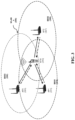
- FIG. 3 shows an example of WLANs for multi-user timing measurement protocol.
- a wireless communication network (300) in the example includes three Access Points (APs) 311, 321, and 331, which form three BSSs 310, 320, and 330 respectively.
- the WLAN 300 also contains one wireless station (312) which may associate with AP1 311 in this example. Three BSSes may be overlapped in the coverage area so that the wireless station (312) could be able to receive/transmit the radio signal from/to those APs, 311, 321 and 331.
- the APs 311, 321 and 331 are MU-TM capable access points and broadcast the MU-TM capability information in the management frame periodically or per-request, such as beacon frames, probe response frames, etc.
- Those APs are operating in the same frequency channel and may support wider bandwidth such as 80 MHz or 160 MHz in addition to 20 MHz bandwidth.
- the station 312 is in the coverage area of three BSSs. It can receive the management and other types of frames from all the APs 311, 321 and 331.
- the APs broadcast the MU-TM capability indication in the management frames such as beacon frames. If the station 312 receives the management frames of APs and knows that MU-TM are supported, it may perform the MU-TM based message exchanges with the APs 311, 321 and 331 for the geo-positioning.
- the station 312 may also acquire the local map, floorplan and other geographic reference information from APs 311, 321 and 331 so that it can determine its relative position to those reference points.
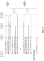
- FIG. 4 illustrates an example of message exchanges of the MU-TM protocol.
- the timing measurement for geo-positioning involves one initiating station (iSTA), and three responding stations (rSTA1), (rSTA2) and (rSTA3).
- the responding stations could be Access Points (APs) or other stations which could provide references of geo-location for the iSTA to determine its position from MU-TM measurements.
- APs Access Points
- MU-TM protocol message exchanges may consist of two phases:
- the responding stations rSTA1, rSTA2 and rSTA3 may use the timing reference transmitted in iSTA for fine timing synchronization.
- the detail of an exemplary MU-TM message exchanges is as follows:
- iSTA can calculate the RTD between iSTA and rSTA2, iSTA and rSTA3 respectively:
- RTD 2 Sum ToA i ⁇ ToD i ⁇ ToD 2 i ⁇ ToA 2 i / N
- RTD 3 Sum ToA i ⁇ ToD i ⁇ ToD 3 i ⁇ ToA 3 i / N .
- the iSTA may stop sending further MU-TM attempt if the difference between RTD1(n) and RTD1(n-1), RTD2(n) and RTD2(n-1) and RTD3(n) and RTD3(n-1) are less than a threshold. In other embodiments, the differences may be compared to distinct thresholds. 407.
- the iSTA may optionally send the MU-TM report including its location information to the associated station.
- FIG. 5 illustrates an example of MU-TM message exchange from the time domain point of view. As shown therein, the steps in the time-domain include:
- the transmission time of MU-TM Request or Response is determined by the transmission rate the message size.
- the fixed time delay Td should be set to the value greater than the maximum propagation delay between the initiating station and any responding station so that two consecutive transmissions of MU-TM Responses would not collide each other in the time domain. For example, for coverage of 100 m from the iSTA, the Td could be set to 0.4 ⁇ s.
- the iSTA may stop sending further MU-TM attempt if the difference between two consecutive RTD measurements are less than the given threshold. 507.
- the iSTA may calculate its position to the reference stations based on the timing measurement results, or send the timing measurement report to a location determination server through the AP which it associates with. The location server will then calculate the location information of the iSTA and send the information back.
- the iSTA may explicitly terminate the MU-TM measurement phase via sending a CF-End frame once the timing measurement completes or implicitly terminate via MU-TM OP time-out.
- an MU-TM capable responding station e.g., AP
- should broadcast the MU-TM support indication so that an MU-TM initiating station could easily identify and perform MU-TM based timing measurement with it.
- An MU-TM capable station may include the MU-TM support indication in the BSS Capability or the Neighbour BSS report.
- FIGS. 6A and 6B shows examples of MU-TM support indication in the HE Capability IE and Neighbour BSS report IE, respectively.
- FIGS. 7A-7B illustrate examples of MU-TM message formats which can be used for either initial MU-TM Request/Response in the preparation phase or the MU-TM Request/Response in the timing measurement phase.
- the MU-TM Request can be a Null Data Packet Announcement (NDPA) like frame and the MU-TM Response can be a Null Data Packet (NDP) type of frame in the MU-TM measurement phase.
- NDPA Null Data Packet Announcement
- NDP Null Data Packet
- the MU-TM Request contains fields shown in FIG. 7A , which include:
- the MU-TM Response contains fields shown in FIG. 7B , which include:
- an rSTA may send an NDP based MU-TM Response in an MU-TM attempt except for the last one. If an NDP based MU-TM Response is sent, no MAC frame is attached to the NDP based MU-TM Response.
- the rSTA shall include in the MU-TM Response the ToA (for example ToA1 for rSTA1) and ToD (for example, ToD1 for rSTA1) averaged with the ToA and ToD values in previous MU-TM attempts. Therefore the iSTA can apply the averaged ToA1 and ToD1 to calculate the RTD between iSTA and rSTA1.
- the iSTA may start the first MU-TM attempt with rSTAs. It may repeat the attempt multiple times to improve the timing measurement accuracy. As the information in the MU-TM Request would be same or similar in every MU-TM attempt, the iSTA may simplify the MU-TM Request to further improve MU-TM protocol performance.
- the iSTA can set the Number of Users to "0" (or other special value) to instruct rSTAs to derive the parameters from the setting in the previous MU-TM Request, and not include an individual User Info fields in this MU-TM Request.
- the rSTAs shall derive RUs, ERTs and other parameters from the previous MU-TM Request.
- ERT1(i-1) are either included in the (i-1) MU-TM Request or further derived from previous request or the initial MU-TM Request.
- ERT 3 i ERT 3 i ⁇ 1 .
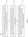
- FIG. 8 shows the wireless communication method 800.
- the method 800 includes, at step 810, transmitting, by a communication apparatus, a timing request to a subset of a plurality of network devices, where the timing request comprises a respective expected response time for each of the subset of the plurality of network devices.
- the timing request identifies a transmission resource associated with each of the subset of the plurality of network devices.
- the communication apparatus may be, for example, a smartphone, a laptop, a tablet, an Internet of Things (IoT) device, or another hardware platform capable of wireless communication.
- IoT Internet of Things
- the method 800 includes, at step 820, receiving, at a plurality of times, a plurality of timing measurements from each of the subset of the plurality of network devices, where each of the plurality of times is based on the corresponding expected response time, and the plurality of timing measurements comprises a respective time of arrival (ToA) timestamp and a respective time of departure (ToD) timestamp.
- ToA time of arrival
- ToD time of departure
- the frame formats shown in FIGS. 7A and 7B may be used for the MU-TM request and the MU-TM response, respectively.
- the method 800 includes, at step 830, determining a location information of the communication apparatus based on an estimate of a round trip delay that is computed using a difference of the respective ToA and ToD timestamps from the plurality of timing measurements.
- the method 800 further includes transmitting, to the plurality of network devices, a plurality of initial timing requests on a plurality of frequency channels, and receiving a plurality of initial timing responses from the subset of the plurality of network devices on a respective frequency channel of the plurality of frequency channels, as described in the context of the MU-TM preparation phase.
- the plurality of initial timing requests is transmitted in an identical timeslot.
- the method 800 further includes repeating steps 810 and 820 a number of times, where a ToA timestamp and a ToD timestamp is received each of the number of times from each of the subset of the plurality of network devices, and refining the estimate of the round trip delay based on a plurality of the ToA timestamps and ToD timestamps.
- the method 800 further includes transmitting, after the steps 810 and 820 are repeated the number of times, a termination message.
- the method 800 further includes transmitting a report comprising the location information of the communication apparatus to the subset of the plurality of network devices.
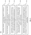
- FIG. 9 shows an example of a wireless communication method, in accordance with some embodiments of the presently disclosed technology. This example includes some features and/or steps that are similar to those shown in FIG. 8 , and described above. At least some of these features and/or components may not be separately described in this section.
- the method 900 includes, at step 910, transmitting a plurality of initial timing requests to a plurality of network devices.
- the method 900 includes, at step 920, receiving a plurality of initial timing responses from a subset of the plurality of network devices.
- the method 900 includes, at step 930, transmitting a timing request to the subset of the plurality of network devices, where the timing request identifies transmission resources to be used by each of the subset of the plurality of network devices.
- the method 900 includes, at step 940, receiving, over the respective transmission resources, a plurality of timing measurements from the subset of the plurality of network devices, where the plurality of timing measurements comprises a respective ToA timestamp and a respective ToD timestamp.
- the method 900 includes, at step 950, determining a location information of the apparatus based on an estimate of a round trip delay that is computed using a difference of the respective ToA and ToD timestamps from the plurality of timing measurements.
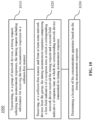
- FIG. 10 shows an example of a wireless communication method, in accordance with some embodiments of the presently disclosed technology.
- This example includes some features and/or steps that are similar to those shown in FIGS. 8 and 9 , and described above. At least some of these features and/or components may not be separately described in this section.
- the method 1000 includes, at step 1010, transmitting, to a group of network devices, a timing request soliciting time measurement responses, the timing request including information for receiving the time measurement responses in a collision-free manner.
- the collision-free manner comprises time-division multiplexing (TDM).
- the collision-free manner comprises frequency-domain multiplexing (FDM).
- other collision-free communication techniques such as code division multiplexing may be used.
- the method 1000 includes, at step 1020, receiving, in the collision-free manner, the timing measurement responses from at least some network devices from the group, where each timing measurement response includes a first field indicative of a reception time at which a corresponding network device received the timing request and a second field indicative of response time at which the corresponding network device transmitted its timing measurement response.
- the method 1000 includes, at step 1030, determining a location of the communication apparatus based on the timing measurement responses.
- the method 1000 further includes repeating steps 1010 and 1020 a number of times, where the first and second fields are received the number of times from the at least some network devices from the group, and refining the location of the communication apparatus based on the first and second fields that were received the number of times.
- the method 1000 further includes transmitting, to the group of network devices, a report comprising the location of the communication apparatus.
- FIG. 11 shows an example of a wireless communication method, in accordance with some embodiments of the presently disclosed technology.
- This example includes some features and/or steps that are similar to those shown in FIGS. 8 , 9 and 10 , and described above. At least some of these features and/or components may not be separately described in this section.
- the method 1100 includes, at step 1110, receiving, from a communication apparatus, a timing request comprising a first time of departure (ToD), an expected response time (ERT), and an identification of a transmission resource.
- ToD first time of departure
- ERT expected response time
- the method 1100 includes, at step 1120, transmitting, at a calculated time and over the transmission resource, a timing measurement that comprises a time of arrival (ToA) timestamp and a second ToD timestamp, where the ToA timestamp corresponds to when the timing request was received, where the second ToD timestamp corresponds to the calculated time, and where the second ToD is equal to a sum of the ToA timestamp and the ERT.
- a timing measurement that comprises a time of arrival (ToA) timestamp and a second ToD timestamp
- ToA timestamp corresponds to when the timing request was received
- the second ToD timestamp corresponds to the calculated time
- the second ToD is equal to a sum of the ToA timestamp and the ERT.
- another method based on the embodiments of the disclosed technology enable a wireless system to implement a timing measurement protocol between a wireless station and multiple wireless reference stations for geographic-positioning the wireless station, and may include transmitting a timing measurement request to a plurality of wireless reference stations simultaneously and receiving their timing measurement responses sequentially.
- another method based on the embodiments of the disclosed technology enable a wireless system to initiate the timing measurement with a plurality of wireless reference stations, and to subsequently perform a multi-user timing measurement preparation phase and a timing measurement phase.
- another method based on the embodiments of the disclosed technology enable a wireless system to identify MU-TM-capable wireless reference stations, and set up the timing measurement period with those wireless reference stations in the multi-user timing measurement preparation phase.
- the method may include, in the initial multi-user timing measurement, transmitting a request that includes the identified wireless reference stations, allocated resource units and expected response time for transmitting the timing measurement responses from a plurality of wireless reference stations.
- a plurality of wireless reference stations transmit the timing measurement responses over the allocated resource unit(s) at the specified time slot.
- another method based on the embodiments of the disclosed technology enable a wireless system to instruct a plurality of responding wireless reference stations to transmit a timing measurement response at the specified time so that a plurality of timing measurement responses from a plurality of wireless reference stations can be distributed in time domain to avoid signal collision at the receiving side.
- another method based on the embodiments of the disclosed technology enable a wireless system to repeat the same multi-user timing measurement procedure with the same plurality of wireless reference stations.
- the timing measurement initiating wireless station can improve the geographic-positioning accuracy progressively.
- the timing measurement initiating wireless station may stop the timing measurement procedure once the measurement result is satisfied.
- FIG. 12 is a block diagram representation of a portion of a communication apparatus, in accordance with some embodiments of the presently disclosed technology.
- the apparatus 1205 can include processor electronics 1210 such as a microprocessor that implements one or more of the techniques presented in this document.
- the apparatus 1205 can include transceiver electronics 1215 to send and/or receive wireless signals over one or more communication interfaces such as antenna(s) 1220.
- the apparatus 1205 can include other communication interfaces for transmitting and receiving data.
- Apparatus 1205 can include one or more memories (not explicitly shown) configured to store information such as data and/or instructions.
- the processor electronics 1210 can include at least a portion of the transceiver electronics 1215. In some embodiments, at least some of the disclosed techniques, modules or functions are implemented using the apparatus 1205.
- a computer-readable medium may include removable and non-removable storage devices including, but not limited to, Read Only Memory (ROM), Random Access Memory (RAM), compact discs (CDs), digital versatile discs (DVD), etc. Therefore, the computer-readable media can include a non-transitory storage media.
- program modules may include routines, programs, objects, components, data structures, etc. that perform particular tasks or implement particular abstract data types.
- Computer- or processor-executable instructions, associated data structures, and program modules represent examples of program code for executing steps of the methods disclosed herein. The particular sequence of such executable instructions or associated data structures represents examples of corresponding acts for implementing the functions described in such steps or processes.
- a hardware circuit implementation can include discrete analog and/or digital components that are, for example, integrated as part of a printed circuit board.
- the disclosed components or modules can be implemented as an Application Specific Integrated Circuit (ASIC) and/or as a Field Programmable Gate Array (FPGA) device.
- ASIC Application Specific Integrated Circuit
- FPGA Field Programmable Gate Array
- DSP digital signal processor
- the various components or sub-components within each module may be implemented in software, hardware or firmware.
- the connectivity between the modules and/or components within the modules may be provided using any one of the connectivity methods and media that is known in the art, including, but not limited to, communications over the Internet, wired, or wireless networks using the appropriate protocols.
Landscapes
- Engineering & Computer Science (AREA)
- Computer Networks & Wireless Communication (AREA)
- Physics & Mathematics (AREA)
- Signal Processing (AREA)
- General Physics & Mathematics (AREA)
- Radar, Positioning & Navigation (AREA)
- Remote Sensing (AREA)
- Quality & Reliability (AREA)
- Electromagnetism (AREA)
- Mobile Radio Communication Systems (AREA)
Claims (15)
- Verfahren zur drahtlosen Kommunikation, umfassend:a) Übertragen (810), durch ein Kommunikationsgerät (1205), einer Zeitsteuerungsanforderung an eine Teilmenge einer Vielzahl von Netzwerkvorrichtungen, wobei die Zeitsteuerungsanforderung eine jeweilige erwartete Reaktionszeit für jede Teilmenge der Vielzahl von Netzwerkvorrichtungen umfasst und wobei die erwartete Reaktionszeit einer Übertragungszeit einer Zeitsteuerungsmessung entspricht, die von der entsprechenden Netzwerkvorrichtung der Vielzahl von Netzwerkvorrichtungen empfangen wird;b) Empfangen (820), zu einer Vielzahl von Zeitpunkten, einer Vielzahl von Zeitsteuerungsmessungen von jeder Teilmenge der Vielzahl von Netzwerkvorrichtungen, wobei jeder der Vielzahl von Zeitpunkten auf der entsprechenden erwarteten Reaktionszeit basiert und die Vielzahl von Zeitsteuerungsmessungen einen jeweiligen Ankunftszeitpunkt-, ToA-, Zeitstempel und einen jeweiligen Abfahrtszeitpunkt-, ToD-, Zeitstempel umfasst;c) Bestimmen (830) einer Standortinformation des Kommunikationsgeräts (1205) anhand einer Schätzung einer Round-Trip-Verzögerung, die unter Verwendung einer Differenz der jeweiligen ToA- und ToD-Zeitstempel aus der Vielzahl von Zeitsteuerungsmessungen berechnet wird;Wiederholen der Schritte a) und b) eine Anzahl von Malen, wobei ein ToA-Zeitstempel und ein ToD-Zeitstempel jede der Anzahl von Malen von jeder Teilmenge der Vielzahl von Netzwerkvorrichtungen empfangen wird und wobei die Round-Trip-Verzögerung für jede der Anzahl von Malen für jede Teilmenge der Vielzahl von Netzwerkvorrichtungen berechnet wird; undBeenden des Wiederholens der Schritte a) und b), wenn die Differenz zwischen aufeinanderfolgenden Round-Trip-Verzögerungen kleiner als ein Schwellenwert ist.
- Verfahren nach Anspruch 1, ferner umfassend:Übertragen (910), an die Vielzahl von Netzwerkvorrichtungen, einer Vielzahl von anfänglichen Zeitsteuerungsanforderungen auf einer Vielzahl von Frequenzkanälen; undEmpfangen (920) einer Vielzahl von anfänglichen Zeitsteuerungsreaktionen von der Teilmenge der Vielzahl von Netzwerkvorrichtungen auf einem jeweiligen Frequenzkanal der Vielzahl von Frequenzkanälen.
- Verfahren nach Anspruch 2, wobei die Vielzahl von anfänglichen Zeitsteuerungsanforderungen in einem identischen Zeitfenster übertragen wird.
- Verfahren nach Anspruch 1, ferner umfassend:
Verfeinern der Schätzung der Round-Trip-Verzögerung anhand einer Vielzahl von ToA-Zeitstempeln und ToD-Zeitstempeln. - Verfahren nach Anspruch 4, ferner umfassend:
Übertragen, nachdem die Schritte a) und b) die Anzahl von Malen wiederholt wurden, einer Beendigungsnachricht. - Verfahren nach Anspruch 1, wobei die Zeitsteuerungsanforderung eine Übertragungsressource identifiziert, die jeder Teilmenge der Vielzahl von Netzwerkvorrichtungen zugeordnet ist, und wobei jede der Vielzahl von Zeitsteuerungsmessungen auf der jeweiligen Übertragungsressource empfangen wird, die in der Zeitsteuerungsanforderung identifiziert wird.
- Verfahren nach Anspruch 1, ferner umfassend:
Übertragen eines Berichts, umfassend die Standortinformation des Kommunikationsgeräts (1205), an die Teilmenge der Vielzahl von Netzwerkvorrichtungen. - Gerät (1205) zur drahtlosen Kommunikation, umfassend:einen Prozessor (1210); undeinen nicht-flüchtigen Speicher mit Anweisungen darauf, wobei die Anweisungen bei Ausführung durch den Prozessor den Prozessor veranlassen zum:a) Übertragen einer Vielzahl von anfänglichen Zeitsteuerungsanforderungen an eine Vielzahl von Netzwerkvorrichtungen;b) Empfangen einer Vielzahl von anfänglichen Zeitsteuerungsreaktionen von einer Teilmenge der Vielzahl von Netzwerkvorrichtungen;c) Übertragen einer Zeitsteuerungsanforderung an die Teilmenge der Vielzahl von Netzwerkvorrichtungen, wobei die Zeitsteuerungsanforderung Übertragungsressourcen identifiziert, die von jeder Teilmenge der Vielzahl von Netzwerkvorrichtungen verwendet werden sollen, und wobei die Zeitsteuerungsanforderung eine jeweilige erwartete Reaktionszeit für jede Teilmenge der Vielzahl von Netzwerkvorrichtungen umfasst und wobei die erwartete Reaktionszeit einer Übertragungszeit einer Zeitsteuerungsmessung entspricht, die von der entsprechenden Netzwerkvorrichtung der Vielzahl von Netzwerkvorrichtungen empfangen wird;d) Empfangen, über die jeweiligen Übertragungsressourcen, einer Vielzahl von Zeitsteuerungsmessungen von der Teilmenge der Vielzahl von Netzwerkvorrichtungen, wobei die Vielzahl von Zeitsteuerungsmessungen einen jeweiligen Ankunftszeitpunkt-, ToA-, Zeitstempel und einen jeweiligen Abfahrtszeitpunkt-, ToD-, Zeitstempel umfasst;e) Bestimmen einer Standortinformation des Geräts anhand einer Schätzung einer Round-Trip-Verzögerung, die unter Verwendung einer Differenz der jeweiligen ToA- und ToD-Zeitstempel aus der Vielzahl von Zeitsteuerungsmessungen berechnet wird;Wiederholen der Schritte c) und d) eine Anzahl von Malen, wobei ein ToA-Zeitstempel und ein ToD-Zeitstempel jede der Anzahl von Malen von jeder Teilmenge der Vielzahl von Netzwerkvorrichtungen empfangen wird und wobei die Round-Trip-Verzögerung für jede der Anzahl von Malen für jede Teilmenge der Vielzahl von Netzwerkvorrichtungen berechnet wird; undBeenden des Wiederholens der Schritte c) und d), wenn die Differenz zwischen aufeinanderfolgenden Round-Trip-Verzögerungen kleiner als ein Schwellenwert ist.
- Gerät nach Anspruch 8, wobei die Vielzahl von anfänglichen Zeitsteuerungsanforderungen auf jedem der Vielzahl von Frequenzkanälen übertragen werden und wobei die Vielzahl von anfänglichen Zeitsteuerungsreaktionen auf den entsprechenden jeder der Vielzahl von Frequenzkanälen empfangen werden.
- Gerät nach Anspruch 8, wobei die Vielzahl von anfänglichen Zeitsteuerungsanforderungen in einem identischen Zeitfenster übertragen werden.
- Gerät nach Anspruch 8, wobei der Prozessor ferner veranlasst wird zum:
Verfeinern der Schätzung der Round-Trip-Verzögerung anhand einer Vielzahl von ToA-Zeitstempeln und ToD-Zeitstempeln. - Gerät nach Anspruch 11, wobei der Prozessor ferner veranlasst wird zum:
Übertragen, nachdem die Schritte c) und d) die Anzahl von Malen wiederholt wurden, einer Beendigungsnachricht,. - Computerlesbares Programmmedium, das Code aufweist, der darauf gespeichert ist, wobei der Code, wenn er von einem Prozessor eines Kommunikationsgeräts (1205) ausgeführt wird, den Prozessor veranlasst, ein Verfahren zur drahtlosen Kommunikation zu implementieren, wobei das Verfahren Folgendes umfasst:a) Übertragen, an eine Gruppe von Netzwerkvorrichtungen, einer Zeitsteuerungsanforderung, die Zeitmessungsreaktionen anfordert, wobei die Zeitsteuerungsanforderung Informationen zum kollisionsfreien Empfangen der Zeitmessungsreaktionen beinhaltet, wobei die Zeitsteuerungsanforderung eine jeweilige erwartete Reaktionszeit für jede der Gruppe von Netzwerkvorrichtungen umfasst, wobei die erwartete Reaktionszeit einer Übertragungszeit einer Zeitsteuerungsmessungsreaktion entspricht, die von einer entsprechenden Netzwerkvorrichtung der Gruppe von Netzwerkvorrichtungen empfangen wird;b) kollisionsfreies Empfangen der Zeitsteuerungsmessungsreaktionen von mindestens einigen Netzwerkvorrichtungen aus der Gruppe, wobei jede Zeitsteuerungsmessungsreaktion ein erstes Feld beinhaltet, das eine Empfangszeit angibt, zu der eine entsprechende Netzwerkvorrichtung die Zeitsteuerungsanforderung empfangen hat, und ein zweites Feld, das die Reaktionszeit angibt, zu der die entsprechende Netzwerkvorrichtung dessen Zeitsteuerungsmessungsreaktion übertragen hat;c) Bestimmen eines Standorts des Kommunikationsgeräts (1205) anhand der Zeitsteuerungsmessungsreaktionen;Wiederholen der Schritte a) und b) eine Anzahl von Malen, wobei ein ToA-Zeitstempel und ein ToD-Zeitstempel jede der Anzahl von Malen von jeder Teilmenge der Vielzahl von Netzwerkvorrichtungen empfangen wird und wobei die Round-Trip-Verzögerung für jede der Anzahl von Malen für jede Teilmenge der Vielzahl von Netzwerkvorrichtungen berechnet wird; undBeenden des Wiederholens der Schritte a) und b), wenn die Differenz zwischen aufeinanderfolgenden Round-Trip-Verzögerungen kleiner als ein Schwellenwert ist.
- Computerlesbares Programmmedium nach Anspruch 13, wobei die kollisionsfreie Art und Weise entweder Zeitmultiplex, TDM, oder Frequenzbereichsmultiplexing, FDM, umfasst.
- Computerlesbares Programmmedium nach Anspruch 13, wobei das Verfahren ferner Folgendes umfasst:
Verfeinern des Standorts des Kommunikationsgeräts (1205) anhand der ersten und zweiten Felder, die eine Anzahl von Malen empfangen wurden.
Applications Claiming Priority (2)
| Application Number | Priority Date | Filing Date | Title |
|---|---|---|---|
| US16/114,098 US11096141B2 (en) | 2018-08-27 | 2018-08-27 | Location information determination based on timing measurements in wireless networks |
| PCT/CN2019/100158 WO2020042893A1 (en) | 2018-08-27 | 2019-08-12 | Location information determination based on timing measurements in wireless networks |
Publications (3)
| Publication Number | Publication Date |
|---|---|
| EP3844524A1 EP3844524A1 (de) | 2021-07-07 |
| EP3844524A4 EP3844524A4 (de) | 2022-05-11 |
| EP3844524B1 true EP3844524B1 (de) | 2025-06-18 |
Family
ID=69586612
Family Applications (1)
| Application Number | Title | Priority Date | Filing Date |
|---|---|---|---|
| EP19855908.0A Active EP3844524B1 (de) | 2018-08-27 | 2019-08-12 | Standortinformationsbestimmung basierend auf zeitmessungen in drahtlosen netzwerken |
Country Status (4)
| Country | Link |
|---|---|
| US (1) | US11096141B2 (de) |
| EP (1) | EP3844524B1 (de) |
| CN (1) | CN112771397B (de) |
| WO (1) | WO2020042893A1 (de) |
Families Citing this family (11)
| Publication number | Priority date | Publication date | Assignee | Title |
|---|---|---|---|---|
| US11159972B2 (en) * | 2018-10-31 | 2021-10-26 | Qualcomm Incorporated | Handling of radio frequency front-end group delays for round trip time estimation |
| US10848256B2 (en) | 2018-11-08 | 2020-11-24 | Qualcomm Incorporated | Group delay calibration for carrier aggregation / multi-radio access technology |
| US10932088B2 (en) * | 2019-01-17 | 2021-02-23 | Intel Corporation | Report identification and power control for ranging |
| US20230029233A1 (en) * | 2021-07-26 | 2023-01-26 | Joseph SEOK | Indoor localization using wlan |
| US20230087308A1 (en) * | 2021-09-22 | 2023-03-23 | Cisco Technology, Inc. | Timing measurement (tm)/fine timing measurement (ftm) for ranging and timing |
| US12369011B2 (en) * | 2022-05-06 | 2025-07-22 | Hewlett Packard Enterprise Development Lp | Location identification of access points in a network |
| EP4623591A1 (de) * | 2022-11-23 | 2025-10-01 | Qualcomm Incorporated | Internet-der-dinge (iot)-basierte positionierung |
| CN116367216A (zh) * | 2023-03-03 | 2023-06-30 | 天翼交通科技有限公司 | 用于车路协同的网络质量评估方法、服务器、终端及介质 |
| US20250097774A1 (en) * | 2023-09-19 | 2025-03-20 | Cisco Technology, Inc. | Method and system for enhanced fine timing measurements (ftm) of location in challenging internet of things (iot) environments |
| WO2025129068A1 (en) * | 2023-12-14 | 2025-06-19 | Cisco Technology, Inc. | Finding a sta location with amp devices |
| WO2026010691A1 (en) * | 2024-07-03 | 2026-01-08 | Qualcomm Incorporated | Positional determination techniques with ambient energy harvesting devices |
Family Cites Families (19)
| Publication number | Priority date | Publication date | Assignee | Title |
|---|---|---|---|---|
| US4847781A (en) * | 1986-09-23 | 1989-07-11 | Associated Data Consoltants | Energy management system |
| GB2354073B (en) * | 1996-12-04 | 2001-06-27 | At & T Lab Cambridge Ltd | Detection system for determining position and orientation of objects |
| US7339957B2 (en) * | 2002-10-28 | 2008-03-04 | Digital Sun, Inc. | Scheduled transmission in a wireless sensor system |
| JP2010541459A (ja) * | 2007-10-02 | 2010-12-24 | サムスン エレクトロニクス カンパニー リミテッド | 通信システムにおける信号の反復転送 |
| US8958382B2 (en) * | 2010-05-11 | 2015-02-17 | Lg Electronics Inc. | Method and device for receiving downlink signals |
| CN103188791B (zh) * | 2011-12-28 | 2016-07-13 | 华为终端有限公司 | 一种定位方法、客户端及定位系统 |
| US8837316B2 (en) | 2012-06-14 | 2014-09-16 | Qualcomm Incorporated | RTT based ranging system and method |
| US20140073352A1 (en) | 2012-09-11 | 2014-03-13 | Qualcomm Incorporated | Method for precise location determination |
| US10039073B2 (en) * | 2013-01-03 | 2018-07-31 | Qualcomm Incorporated | Method for determining location of wireless devices |
| US8842571B1 (en) * | 2013-02-22 | 2014-09-23 | Marvell International Ltd. | Method and apparatus for determining a time of arrival of a data unit |
| US9226260B2 (en) * | 2013-05-10 | 2015-12-29 | Intel Corporation | Initiator-conditioned fine timing measurement service request |
| US9459337B2 (en) * | 2013-05-30 | 2016-10-04 | Qualcomm Incorporated | Methods and systems for enhanced round trip time (RTT) exchange |
| US9445227B2 (en) | 2013-08-30 | 2016-09-13 | Qualcomm Incorporated | Passive positioning utilizing round trip time information |
| US9277369B2 (en) * | 2014-06-30 | 2016-03-01 | Qualcomm Technologies International, Ltd. | Method for determining location of wireless devices |
| US10182413B2 (en) * | 2014-07-30 | 2019-01-15 | Qualcomm Incorporated | Wireless positioning using scheduled transmissions |
| US9907044B2 (en) | 2014-09-15 | 2018-02-27 | Qualcomm Incorporated | IEEE 802.11 enhancements for high efficiency positioning |
| US10158547B2 (en) | 2014-10-27 | 2018-12-18 | Qualcomm Incorporated | Method for a procedure for determining distance or angle between electronic devices connected wirelessly |
| US20170118587A1 (en) | 2015-10-26 | 2017-04-27 | Microsoft Technology Licensing, Llc | Location detection using bulk fine timing |
| CN109511169B (zh) * | 2017-09-15 | 2024-01-05 | 华为技术有限公司 | 一种控制资源集合的获取方法、装置以及系统 |
-
2018
- 2018-08-27 US US16/114,098 patent/US11096141B2/en active Active
-
2019
- 2019-08-12 WO PCT/CN2019/100158 patent/WO2020042893A1/en not_active Ceased
- 2019-08-12 CN CN201980057185.0A patent/CN112771397B/zh active Active
- 2019-08-12 EP EP19855908.0A patent/EP3844524B1/de active Active
Also Published As
| Publication number | Publication date |
|---|---|
| US11096141B2 (en) | 2021-08-17 |
| EP3844524A1 (de) | 2021-07-07 |
| WO2020042893A1 (en) | 2020-03-05 |
| CN112771397A (zh) | 2021-05-07 |
| US20200068521A1 (en) | 2020-02-27 |
| CN112771397B (zh) | 2023-10-31 |
| EP3844524A4 (de) | 2022-05-11 |
Similar Documents
| Publication | Publication Date | Title |
|---|---|---|
| EP3844524B1 (de) | Standortinformationsbestimmung basierend auf zeitmessungen in drahtlosen netzwerken | |
| US10624055B2 (en) | Method for determining location of wireless devices | |
| EP3039925B1 (de) | Mehrantennen-ap-positionierung in drahtlosen lokalen netzwerken | |
| US9277369B2 (en) | Method for determining location of wireless devices | |
| EP3039826B1 (de) | Entfernungsmessung und positionierung in wlans unter verwendung von zeitstempeln eines benachbarten zugangspunkts und einer schnüffelnden station | |
| EP3100543B1 (de) | Funkpeilung und ftm-positionierung in drahtlosen lokalen netzwerken | |
| US9769626B2 (en) | Fine timing measurement positioning and improvements in wireless local area networks | |
| US20190306825A1 (en) | Access point (ap) to access point (ap) ranging for passive locationing | |
| US9288625B2 (en) | Method for determining location of wireless devices based on information within messages received from other network devices | |
| CN111919477B (zh) | 用于支持天线切换的测距协议改进 | |
| US9971014B2 (en) | Access point-assisted positioning framework | |
| KR20230170671A (ko) | 적응적 레인징 트리거로의 위치 프로토콜 | |
| US20160150500A1 (en) | High accuracy ofdma downlink rtt measurement | |
| US20220039058A1 (en) | Methods and apparatus for wi-fi ranging protocol enhancement with reduced throughput impact | |
| US20240357543A1 (en) | Method and apparatus for performing positioning based on sidelink prs in wireless communication system | |
| US20250028039A1 (en) | Carrier-phase reporting in wifi ranging | |
| WO2018067044A1 (en) | Methods and apparatus for performing timing measurement in a wireless network | |
| CN119497137A (zh) | 一种信息传输方法和装置 |
Legal Events
| Date | Code | Title | Description |
|---|---|---|---|
| STAA | Information on the status of an ep patent application or granted ep patent |
Free format text: STATUS: THE INTERNATIONAL PUBLICATION HAS BEEN MADE |
|
| STAA | Information on the status of an ep patent application or granted ep patent |
Free format text: STATUS: REQUEST FOR EXAMINATION WAS MADE |
|
| PUAI | Public reference made under article 153(3) epc to a published international application that has entered the european phase |
Free format text: ORIGINAL CODE: 0009012 |
|
| 17P | Request for examination filed |
Effective date: 20210326 |
|
| AK | Designated contracting states |
Kind code of ref document: A1 Designated state(s): AL AT BE BG CH CY CZ DE DK EE ES FI FR GB GR HR HU IE IS IT LI LT LU LV MC MK MT NL NO PL PT RO RS SE SI SK SM TR |
|
| DAV | Request for validation of the european patent (deleted) | ||
| DAX | Request for extension of the european patent (deleted) | ||
| A4 | Supplementary search report drawn up and despatched |
Effective date: 20220408 |
|
| RIC1 | Information provided on ipc code assigned before grant |
Ipc: H04L 43/0864 20220101ALN20220404BHEP Ipc: H04W 84/12 20090101ALN20220404BHEP Ipc: G01S 5/14 20060101ALI20220404BHEP Ipc: G01S 5/02 20100101ALI20220404BHEP Ipc: H04W 64/00 20090101ALI20220404BHEP Ipc: G01S 5/10 20060101AFI20220404BHEP |
|
| GRAP | Despatch of communication of intention to grant a patent |
Free format text: ORIGINAL CODE: EPIDOSNIGR1 |
|
| STAA | Information on the status of an ep patent application or granted ep patent |
Free format text: STATUS: GRANT OF PATENT IS INTENDED |
|
| RIC1 | Information provided on ipc code assigned before grant |
Ipc: H04L 43/0864 20220101ALN20250220BHEP Ipc: H04W 84/12 20090101ALN20250220BHEP Ipc: G01S 5/14 20060101ALI20250220BHEP Ipc: G01S 5/02 20100101ALI20250220BHEP Ipc: H04W 64/00 20090101ALI20250220BHEP Ipc: G01S 5/10 20060101AFI20250220BHEP |
|
| RIC1 | Information provided on ipc code assigned before grant |
Ipc: H04L 43/0864 20220101ALN20250225BHEP Ipc: H04W 84/12 20090101ALN20250225BHEP Ipc: G01S 5/14 20060101ALI20250225BHEP Ipc: G01S 5/02 20100101ALI20250225BHEP Ipc: H04W 64/00 20090101ALI20250225BHEP Ipc: G01S 5/10 20060101AFI20250225BHEP |
|
| INTG | Intention to grant announced |
Effective date: 20250305 |
|
| GRAS | Grant fee paid |
Free format text: ORIGINAL CODE: EPIDOSNIGR3 |
|
| GRAA | (expected) grant |
Free format text: ORIGINAL CODE: 0009210 |
|
| STAA | Information on the status of an ep patent application or granted ep patent |
Free format text: STATUS: THE PATENT HAS BEEN GRANTED |
|
| AK | Designated contracting states |
Kind code of ref document: B1 Designated state(s): AL AT BE BG CH CY CZ DE DK EE ES FI FR GB GR HR HU IE IS IT LI LT LU LV MC MK MT NL NO PL PT RO RS SE SI SK SM TR |
|
| REG | Reference to a national code |
Ref country code: GB Ref legal event code: FG4D |
|
| REG | Reference to a national code |
Ref country code: CH Ref legal event code: EP |
|
| REG | Reference to a national code |
Ref country code: DE Ref legal event code: R096 Ref document number: 602019071360 Country of ref document: DE |
|
| REG | Reference to a national code |
Ref country code: CH Ref legal event code: EP |
|
| REG | Reference to a national code |
Ref country code: IE Ref legal event code: FG4D |
|
| PGFP | Annual fee paid to national office [announced via postgrant information from national office to epo] |
Ref country code: FR Payment date: 20250610 Year of fee payment: 7 |
|
| PG25 | Lapsed in a contracting state [announced via postgrant information from national office to epo] |
Ref country code: FI Free format text: LAPSE BECAUSE OF FAILURE TO SUBMIT A TRANSLATION OF THE DESCRIPTION OR TO PAY THE FEE WITHIN THE PRESCRIBED TIME-LIMIT Effective date: 20250618 |
|
| PGFP | Annual fee paid to national office [announced via postgrant information from national office to epo] |
Ref country code: DE Payment date: 20250618 Year of fee payment: 7 |
|
| REG | Reference to a national code |
Ref country code: LT Ref legal event code: MG9D |
|
| PG25 | Lapsed in a contracting state [announced via postgrant information from national office to epo] |
Ref country code: GR Free format text: LAPSE BECAUSE OF FAILURE TO SUBMIT A TRANSLATION OF THE DESCRIPTION OR TO PAY THE FEE WITHIN THE PRESCRIBED TIME-LIMIT Effective date: 20250919 Ref country code: NO Free format text: LAPSE BECAUSE OF FAILURE TO SUBMIT A TRANSLATION OF THE DESCRIPTION OR TO PAY THE FEE WITHIN THE PRESCRIBED TIME-LIMIT Effective date: 20250918 |
|
| PG25 | Lapsed in a contracting state [announced via postgrant information from national office to epo] |
Ref country code: BG Free format text: LAPSE BECAUSE OF FAILURE TO SUBMIT A TRANSLATION OF THE DESCRIPTION OR TO PAY THE FEE WITHIN THE PRESCRIBED TIME-LIMIT Effective date: 20250618 |
|
| PG25 | Lapsed in a contracting state [announced via postgrant information from national office to epo] |
Ref country code: HR Free format text: LAPSE BECAUSE OF FAILURE TO SUBMIT A TRANSLATION OF THE DESCRIPTION OR TO PAY THE FEE WITHIN THE PRESCRIBED TIME-LIMIT Effective date: 20250618 |
|
| PG25 | Lapsed in a contracting state [announced via postgrant information from national office to epo] |
Ref country code: RS Free format text: LAPSE BECAUSE OF FAILURE TO SUBMIT A TRANSLATION OF THE DESCRIPTION OR TO PAY THE FEE WITHIN THE PRESCRIBED TIME-LIMIT Effective date: 20250918 |
|
| REG | Reference to a national code |
Ref country code: NL Ref legal event code: MP Effective date: 20250618 |
|
| PG25 | Lapsed in a contracting state [announced via postgrant information from national office to epo] |
Ref country code: LV Free format text: LAPSE BECAUSE OF FAILURE TO SUBMIT A TRANSLATION OF THE DESCRIPTION OR TO PAY THE FEE WITHIN THE PRESCRIBED TIME-LIMIT Effective date: 20250618 |
|
| PG25 | Lapsed in a contracting state [announced via postgrant information from national office to epo] |
Ref country code: NL Free format text: LAPSE BECAUSE OF FAILURE TO SUBMIT A TRANSLATION OF THE DESCRIPTION OR TO PAY THE FEE WITHIN THE PRESCRIBED TIME-LIMIT Effective date: 20250618 |
|
| PG25 | Lapsed in a contracting state [announced via postgrant information from national office to epo] |
Ref country code: PT Free format text: LAPSE BECAUSE OF FAILURE TO SUBMIT A TRANSLATION OF THE DESCRIPTION OR TO PAY THE FEE WITHIN THE PRESCRIBED TIME-LIMIT Effective date: 20251020 |
|
| REG | Reference to a national code |
Ref country code: AT Ref legal event code: MK05 Ref document number: 1804663 Country of ref document: AT Kind code of ref document: T Effective date: 20250618 |
|
| PG25 | Lapsed in a contracting state [announced via postgrant information from national office to epo] |
Ref country code: IS Free format text: LAPSE BECAUSE OF FAILURE TO SUBMIT A TRANSLATION OF THE DESCRIPTION OR TO PAY THE FEE WITHIN THE PRESCRIBED TIME-LIMIT Effective date: 20251018 |
|
| PG25 | Lapsed in a contracting state [announced via postgrant information from national office to epo] |
Ref country code: AT Free format text: LAPSE BECAUSE OF FAILURE TO SUBMIT A TRANSLATION OF THE DESCRIPTION OR TO PAY THE FEE WITHIN THE PRESCRIBED TIME-LIMIT Effective date: 20250618 Ref country code: SM Free format text: LAPSE BECAUSE OF FAILURE TO SUBMIT A TRANSLATION OF THE DESCRIPTION OR TO PAY THE FEE WITHIN THE PRESCRIBED TIME-LIMIT Effective date: 20250618 |
|
| PG25 | Lapsed in a contracting state [announced via postgrant information from national office to epo] |
Ref country code: CZ Free format text: LAPSE BECAUSE OF FAILURE TO SUBMIT A TRANSLATION OF THE DESCRIPTION OR TO PAY THE FEE WITHIN THE PRESCRIBED TIME-LIMIT Effective date: 20250618 |
|
| PG25 | Lapsed in a contracting state [announced via postgrant information from national office to epo] |
Ref country code: PL Free format text: LAPSE BECAUSE OF FAILURE TO SUBMIT A TRANSLATION OF THE DESCRIPTION OR TO PAY THE FEE WITHIN THE PRESCRIBED TIME-LIMIT Effective date: 20250618 |
|
| PG25 | Lapsed in a contracting state [announced via postgrant information from national office to epo] |
Ref country code: EE Free format text: LAPSE BECAUSE OF FAILURE TO SUBMIT A TRANSLATION OF THE DESCRIPTION OR TO PAY THE FEE WITHIN THE PRESCRIBED TIME-LIMIT Effective date: 20250618 |
|
| PG25 | Lapsed in a contracting state [announced via postgrant information from national office to epo] |
Ref country code: SK Free format text: LAPSE BECAUSE OF FAILURE TO SUBMIT A TRANSLATION OF THE DESCRIPTION OR TO PAY THE FEE WITHIN THE PRESCRIBED TIME-LIMIT Effective date: 20250618 Ref country code: RO Free format text: LAPSE BECAUSE OF FAILURE TO SUBMIT A TRANSLATION OF THE DESCRIPTION OR TO PAY THE FEE WITHIN THE PRESCRIBED TIME-LIMIT Effective date: 20250618 |
|
| PG25 | Lapsed in a contracting state [announced via postgrant information from national office to epo] |
Ref country code: ES Free format text: LAPSE BECAUSE OF FAILURE TO SUBMIT A TRANSLATION OF THE DESCRIPTION OR TO PAY THE FEE WITHIN THE PRESCRIBED TIME-LIMIT Effective date: 20250618 |
|
| REG | Reference to a national code |
Ref country code: CH Ref legal event code: H13 Free format text: ST27 STATUS EVENT CODE: U-0-0-H10-H13 (AS PROVIDED BY THE NATIONAL OFFICE) Effective date: 20260324 |
|
| PG25 | Lapsed in a contracting state [announced via postgrant information from national office to epo] |
Ref country code: MC Free format text: LAPSE BECAUSE OF FAILURE TO SUBMIT A TRANSLATION OF THE DESCRIPTION OR TO PAY THE FEE WITHIN THE PRESCRIBED TIME-LIMIT Effective date: 20250618 |
|
| PG25 | Lapsed in a contracting state [announced via postgrant information from national office to epo] |
Ref country code: DK Free format text: LAPSE BECAUSE OF FAILURE TO SUBMIT A TRANSLATION OF THE DESCRIPTION OR TO PAY THE FEE WITHIN THE PRESCRIBED TIME-LIMIT Effective date: 20250618 |
|
| PG25 | Lapsed in a contracting state [announced via postgrant information from national office to epo] |
Ref country code: LU Free format text: LAPSE BECAUSE OF NON-PAYMENT OF DUE FEES Effective date: 20250812 Ref country code: IT Free format text: LAPSE BECAUSE OF FAILURE TO SUBMIT A TRANSLATION OF THE DESCRIPTION OR TO PAY THE FEE WITHIN THE PRESCRIBED TIME-LIMIT Effective date: 20250618 |
|
| PG25 | Lapsed in a contracting state [announced via postgrant information from national office to epo] |
Ref country code: CH Free format text: LAPSE BECAUSE OF NON-PAYMENT OF DUE FEES Effective date: 20250831 |
|
| PLBE | No opposition filed within time limit |
Free format text: ORIGINAL CODE: 0009261 |
|
| STAA | Information on the status of an ep patent application or granted ep patent |
Free format text: STATUS: NO OPPOSITION FILED WITHIN TIME LIMIT |
|
| REG | Reference to a national code |
Ref country code: CH Ref legal event code: L10 Free format text: ST27 STATUS EVENT CODE: U-0-0-L10-L00 (AS PROVIDED BY THE NATIONAL OFFICE) Effective date: 20260430 |