EP3844579B1 - Procédé, dispositif et système pour déterminer des informations de mesure - Google Patents
Procédé, dispositif et système pour déterminer des informations de mesure Download PDFInfo
- Publication number
- EP3844579B1 EP3844579B1 EP19728345.0A EP19728345A EP3844579B1 EP 3844579 B1 EP3844579 B1 EP 3844579B1 EP 19728345 A EP19728345 A EP 19728345A EP 3844579 B1 EP3844579 B1 EP 3844579B1
- Authority
- EP
- European Patent Office
- Prior art keywords
- forming
- measurement information
- parameters
- measurement
- boundary conditions
- Prior art date
- Legal status (The legal status is an assumption and is not a legal conclusion. Google has not performed a legal analysis and makes no representation as to the accuracy of the status listed.)
- Active
Links
Images



Classifications
-
- G—PHYSICS
- G05—CONTROLLING; REGULATING
- G05B—CONTROL OR REGULATING SYSTEMS IN GENERAL; FUNCTIONAL ELEMENTS OF SUCH SYSTEMS; MONITORING OR TESTING ARRANGEMENTS FOR SUCH SYSTEMS OR ELEMENTS
- G05B19/00—Program-control systems
- G05B19/02—Program-control systems electric
- G05B19/18—Numerical control [NC], i.e. automatically operating machines, in particular machine tools, e.g. in a manufacturing environment, so as to execute positioning, movement or co-ordinated operations by means of program data in numerical form
- G05B19/406—Numerical control [NC], i.e. automatically operating machines, in particular machine tools, e.g. in a manufacturing environment, so as to execute positioning, movement or co-ordinated operations by means of program data in numerical form characterised by monitoring or safety
- G05B19/4069—Simulating machining process on screen
-
- G—PHYSICS
- G06—COMPUTING OR CALCULATING; COUNTING
- G06F—ELECTRIC DIGITAL DATA PROCESSING
- G06F30/00—Computer-aided design [CAD]
- G06F30/20—Design optimisation, verification or simulation
- G06F30/23—Design optimisation, verification or simulation using finite element methods [FEM] or finite difference methods [FDM]
-
- G—PHYSICS
- G06—COMPUTING OR CALCULATING; COUNTING
- G06F—ELECTRIC DIGITAL DATA PROCESSING
- G06F2111/00—Details relating to CAD techniques
- G06F2111/08—Probabilistic or stochastic CAD
-
- G—PHYSICS
- G06—COMPUTING OR CALCULATING; COUNTING
- G06F—ELECTRIC DIGITAL DATA PROCESSING
- G06F2113/00—Details relating to the application field
- G06F2113/24—Sheet material
Definitions
- the invention relates to a method for determining measurement information for a forming process to be carried out on a metal part, in particular for steel or aluminum forming, the method being carried out by at least a first and/or a second device.
- the invention further relates to a device which is designed or comprises corresponding means for carrying out and/or controlling a method according to the invention, as well as a system of devices.
- the forming processes can be monitored during operation and to regulate the tools used. Measurement values could be taken during the forming process using suitable sensors and the forming process could be regulated according to the measurement values. If the forming tools used are designed to react accordingly, the forming process can be regulated taking the measurement values into account in such a way that, for example, the creation of defective metal parts and thus rejects can be reduced or avoided.
- the problem with such process control is that, due to the tool design and the process, not all relevant measured variables can be monitored at all possible positions of the metal part to be formed during the forming process. If, for example, too many sensors are provided, the functionality of a tool can be drastically reduced. An optical analysis for cracks cannot be carried out in a closed tool, for example. Also, not every sensor or every measuring method is suitable for implementation in a forming process, so in principle not all relevant measured variables can be monitored. For example, the residual formability (i.e.
- Suitable measurement information must therefore be determined in advance of a forming process that allows the forming process to be monitored as comprehensively as possible by measuring individual, as few measured variables as possible at specific, as few positions as possible and to reliably detect deviations in the formed metal part from the target values to be achieved at such an early stage that the further forming process can be controlled in such a way that the target values are adhered to as far as possible in the finished formed metal part.
- determining suitable measurement information is problematic and is hardly feasible, especially through experiments.
- the present invention is based on the object of specifying a method with which a forming process to be carried out can be efficiently controlled so that the formation of defective metal parts or scrap is reduced or largely avoided.
- a device and a system for solving the problem are to be proposed.
- the above-mentioned object is achieved with a method for determining measurement information for a forming process to be carried out on a metal part, in particular for steel or aluminum forming, wherein the method comprises the following: Obtaining forming boundary conditions of the forming process to be carried out from a first device on the second device; Obtaining and/or determining material parameters of the metal part and/or process parameters of the forming process to be carried out; Carrying out and/or initiating the carrying out of at least one forming simulation based on the forming boundary conditions and the material parameters and/or process parameters; determining measurement information based at least partially on the at least one forming simulation; and providing the measurement information from the second device to the first device.
- Measurement information can be, for example, the position and/or type of a necessary measurement. Based on this measurement information, a control loop for a forming process to be carried out can then be implemented.
- forming simulations can also be used to determine optimal process parameters and assess the feasibility of the forming process. Corresponding forming simulations are usually based on a finite element method (FEM).
- FEM finite element method
- a customer of semi-finished products to be produced does not usually have all the necessary parameters and boundary conditions to be able to carry out a forming simulation with the necessary accuracy.
- the customer is usually aware of the target values to be achieved and the forming boundary conditions, but only individual characteristic values of the material parameters are usually available to him.
- a customer may also be aware of requirements for process parameters.
- the actual process parameters are usually not available to him or not with the necessary accuracy.
- a sufficiently precise knowledge of the parameters for a comprehensive simulation of the forming process in order to obtain reliable measurement information cannot therefore be readily available to the customers.
- the manufacturers of the semi-finished products or the base materials may know a large number of material parameters and process parameters, but such information may need to be kept confidential and is also subject to strong fluctuations, for example if manufacturing processes are changed or renewed over time.
- the material and process parameters used by the customer for the forming simulations may therefore not be sufficient for a realistic estimate of the expected robustness of the forming, so that no statement can be made as to how the robustness can be increased, for example, by a control or regulation circuit based on measurement information.
- the implementation of control or regulation circuits e.g. by installing sensors in the forming tools and a variation of the press forces induced by the sensor data, variation of the hold-down forces, adjustment of the drawing distances and/or additional oiling, can only be achieved to a limited extent for the customer.
- the forming boundary conditions of the forming to be carried out should be received from a first device on the second device, for example a computer of a manufacturer of semi-finished products. If the second device now receives or determines material parameters of the metal part and/or process parameters of the forming to be carried out, at least one forming simulation can be carried out or triggered based on the forming boundary conditions and the material parameters and/or process parameters. At least partially based on this, measurement information can be determined and provided by the second device to the first device.
- the forming boundary conditions are obtained from the second device, e.g. via an input interface.
- the forming boundary conditions can be provided, forwarded and/or generated by the first device, wherein the first device communicates with the second device.
- the first device may be a different device than the second device or the first device is an external device compared to the second device.
- the first and second devices may be spatially separated, have separate resources and/or are not in constant communication.
- the first device is assigned to a buyer of semi-finished products and/or the second device is assigned to a manufacturer of semi-finished products and/or a (further) service provider with access to the material parameters.
- Forming boundary conditions are understood to be conditions which at least partially allow a forming simulation to be carried out.
- the forming boundary conditions include geometric conditions such as initial geometry and/or target geometry of the forming, information indicative of one or more materials for the forming, for example the type of material, for example a steel grade, for example in accordance with DIN EN 10027, or an aluminum grade, for example in accordance with DIN EN 573, or a material number, a chemical composition and/or a mechanical and/or thermal pretreatment, material and/or process parameters.
- forming boundary conditions can be obtained in the form of CAD data.
- the method can provide that the second device queries the addition of the forming boundary conditions, for example from the first device, and/or triggers a query.
- the second device can provide a preselection of possible additions and, for example, generate a recommendation of the additions.
- the purchaser of semi-finished products is asked to complete the forming boundary conditions on the first device.
- forming boundary conditions are understood to mean information that is typically known to a purchaser of semi-finished products or base materials. The forming boundary conditions are therefore available on the first device in particular.
- the material and/or process parameters described below typically refer to information that is only known to the manufacturer of semi-finished products or base materials.
- the material and/or process parameters are therefore not available on the first device, but for example only on the second device.
- a material parameter can be understood as parameters that are suitable for characterizing the forming properties of the material.
- material parameters can be determined experimentally, for example through tensile tests and/or hydraulic cupping tests, and/or at least derived from experiments.
- Material parameters can also be understood as correlations between other material parameters and/or experimental data.
- material parameters are indicative of a stress-strain diagram, elastic modulus, Poisson's ratio, yield strength, yield point, tensile strength, uniform elongation, hardening exponent, anisotropy coefficient, friction coefficient, surface roughness, elongation at break and/or area at break of a material or several materials.
- a process parameter is understood to be a parameter that is indicative of the process being carried out.
- process parameters include speed, temperature, pressure, forces, distances, position of the metal part (circuit board, piece of sheet metal), type and/or shape of the forming tools. Friction conditions such as the type, quantity, distribution and/or application of lubricants such as lubricating oil can also be understood as process parameters.
- At least one forming simulation based on the forming boundary conditions and the material parameters and/or process parameters is now carried out by the second device or its implementation is triggered.
- a third device is provided or a system of third devices which are set up to carry out forming simulations.
- the third device(s) is/are preferably not in direct communication with the first device.
- the forming simulations can be based on a finite element method (FEM) and/or static methods, such as a Monte Carlo method (MC) and/or Latin Hypercube sampling.
- FEM finite element method
- MC Monte Carlo method
- a forming simulation can also be carried out on at least one third device, so that the third device at least partially takes over the task of the second device and the second device carries out the calculation.
- Measurement information characterizes or specifies in particular (at least) one measurement process that is to take place during the forming to be carried out, and can therefore in particular represent a specification, for example with regard to at least one measurement process to be carried out during the forming to be carried out.
- the measurement information indicates, for example, which measurement variables can be used sensibly ("measurement variable information") and/or which sensor positions can be used (“measurement position information”) and/or which type of detection can be used.
- the measurement information can thus indicate, for example, which sensor type (e.g. inlet sensor and/or pressure sensor, e.g. a piezo pressure module) is to be used and/or which measurement method (e.g.
- the measurement information can also indicate a predicted time at which a certain measurement is to be carried out.
- the measurement information specifies or characterizes (at least) one measurement process in particular, which can be used to determine whether there could be a significant deviation from the target values to be achieved in the finished formed metal part.
- Target values or "quality values" are properties to be achieved in the metal part after forming. A deviation is significant if it exceeds the permissible tolerances.
- Target values are usually specified by the customer for semi-finished products to be manufactured and can therefore be included in particular in the forming boundary conditions.
- forming results representative of the result of the forming to be carried out predicted based on the at least one forming simulation can be determined, in particular by the second device. Based on the forming results, the measurement information can then be determined, for example. If required, the forming results can be provided to the first device.
- Forming results and target variables can in particular relate to the same properties of a formed metal part. Forming results and target variables can, for example, be dimensions to be achieved or also safety to be achieved, in particular against constrictions. Forming results and target variables can, for example, include a strain distribution, for example a two- or three-dimensional spatial strain distribution of the material in a target geometry.
- the strain distribution is weighted based on the geometry, i.e. certain parts of the target geometry are, for example, particularly evaluated as target variables.
- Forming results and target values may also include a comparison of a strain distribution with at least one forming limit curve (FLC), for example a difference to values of a forming limit curve.
- FLC forming limit curve
- the first device which is assigned to a buyer of semi-finished products, for example, does not have to maintain a database for material and/or process parameters itself, nor does it have to provide the capacity to carry out a series of forming simulations for a large number of different material parameters. On the other hand, it can be ensured that the forming simulations are always based on current and manufacturer-specific material and/or process parameters.
- the second device is assigned to a manufacturer of semi-finished products or basic materials, whereby the material and/or process parameters can be kept up to date in a simple manner. If, for example, manufacturing processes are changed or renewed over time and new test results are available, the process can be used to ensure that that the forming simulations are not based on inaccurate or incomplete material and/or process parameters. The accuracy of the forming results and the measurement information is improved accordingly.
- the forming boundary conditions can already contain information indicative of one or more materials for forming, so that, for example, the customer specifies the type of steel or aluminum to be used.
- the information indicative of one or more materials for forming is at least partially determined based on the forming boundary conditions, e.g. by the second or third device.
- the information indicative of one or more materials for forming is determined based on the forming boundary conditions, for example using a database comprising such information.
- forming simulations can also be carried out and, on the basis of forming results, suitable information indicative of one or more materials for forming, for example a suitable type of steel or aluminum, can be determined that is representative of the result of the forming to be carried out predicted based on the at least one forming simulation.
- the forming boundary conditions can already contain at least some process parameters.
- a customer can specify which process should be used or at what speed a process should run.
- the process parameters are determined at least in part based on the forming boundary conditions, e.g. by the second or third device.
- the measurement information comprises measurement variable information indicative of one or more measurement variables to be determined during the forming process to be carried out and/or measurement position information indicative of one or more positions of one or more sensors to be used during the forming process to be carried out.
- the measurement information can be specify a sensor type and/or a measuring method for measuring a measurand to be determined.
- the method also comprises obtaining and/or determining a distribution of material parameters of the metal part and/or process parameters of the forming to be carried out, wherein the carrying out and/or triggering of the carrying out of the at least one forming simulation is based on the forming boundary conditions and the distribution of material parameters and/or process parameters.
- a distribution of material parameters of the metal part and/or process parameters of the forming to be carried out is determined and/or obtained.
- a distribution of material parameters of the metal part is characteristic of fluctuations in the forming properties of the materials to be formed.
- a database is provided which contains a distribution of material parameters for a large number of materials, wherein the distribution of material parameters is queried from the database in particular by the second device.
- the distribution of material parameters can be understood as a set of data which is indicative of the fluctuations in the material parameters of the metal part. For example, it is a set of data from a series of experimental results and/or statistical parameters (arithmetic mean, root mean square, expected value, and/or variance/scatter, e.g. from a series of experimental results).
- a distribution of process parameters of the forming to be carried out is, for example, characteristic of fluctuations in the parameters of the forming to be carried out.
- a database is provided which contains a distribution of process parameters for a large number of manufacturing processes, wherein the distribution of process parameters is retrieved from the database, in particular by the second device.
- the distribution of process parameters can be understood as a set of data which is indicative of the fluctuations of the process parameters. For example, it is a set of data from a series of experimental results and/or statistical parameters.
- the first device is not involved in determining the material parameters of the metal part and/or process parameters of the forming to be carried out.
- fluctuations in the conditions for example in the material and/or process parameters in the first device and/or in the second device, can also be specified.
- a distribution of material and/or process parameters makes it possible to specify probabilities with which conditions arise in the manufacturing process that lead to the production of defective metal parts. For example, a distribution of forming results is provided by one or more forming simulations based on the distribution of material and/or process parameters and these are subjected in particular to an evaluation with regard to target values.
- the forming process can be automatically modified depending on the predicted effect of the measured deviation in the shape or position so that faulty parts are not produced. It is also possible, for example, to predict what effect a deviation in a press force from a set press force will have on compliance with the target dimensions. If the press force is monitored using a sensor, the press force can be increased or reduced, for example, depending on the probability predicted from the distribution of forming results that a deviation from the target dimensions may occur. It can also For example, a blank holder force can be increased or reduced in order to regulate or control the forming process.
- a series of forming simulations are carried out based on the forming boundary conditions, whereby the material parameters or process parameters are varied within the distribution of material parameters or process parameters. This makes it possible, for example, to provide a distribution of forming results for each individual manufacturing process, even if no information is known in advance about the effects of the distribution of material and/or process parameters on achieving the target values.
- the method comprises: determining one or more critical points on a metal part and/or one or more critical points in time during the forming process to be carried out, wherein the determination of measurement information is also based on the one or more determined critical points and/or the one or more critical points in time.
- a critical point is, for example, a position or area on a metal part where there is an increased probability of errors occurring during the forming process, which can lead to deviations from the target values. For example, these can occur in sensitive or heavily formed areas of a metal part, for example on edges or in thin areas with low wall thickness. These critical points can then be targeted using suitable sensors. monitored in order to regulate the forming process if necessary in such a way that there are no significant deviations from the target values.
- Critical points in time are understood to be points in time during a forming process at which errors occur that can lead to deviations from the target values. Knowledge of these points in time enables, for example, targeted monitoring and regulation or control of the forming process. For example, in a multi-stage manufacturing process, monitoring a press force in just one stage of the manufacturing process is sufficient to be able to regulate the manufacturing process in such a way that there is no significant deviation from the target values.
- the forming boundary conditions include target values for the forming.
- the target values can be specified by the first device or a customer to whom the first device is assigned, and the forming results can be evaluated with regard to the target values.
- target values can include a risk of cracking, a weighting of certain areas of the initial and/or target geometry, safety against constrictions and/or areas with specified extensions, in particular also minimum metal thicknesses.
- Corresponding target values can also be queried by the second device or a query can be triggered by the first device.
- the forming boundary conditions can also at least partially include the material parameters, whereby, for example, the first device or the customer specifies the material which is to be used in the forming to be carried out or in the forming simulations.
- the method comprises: determining a dependency between target variables on the one hand and material parameters and/or process parameters on the other hand based on the forming simulation or the Forming simulations, whereby the determination of measurement information is also based on the dependency of target variables and material parameters and/or process parameters.
- the material and/or process parameters are each systematically varied (step by step) from a minimum to a maximum value and the influence on the target variables is represented by a functional dependency.
- a regression is carried out with a determination of coefficients.
- the functional dependency the fluctuations in the material parameters that occur can thus be easily taken into account in the forming results, making it particularly easy to determine critical points and/or points in time.
- the method comprises: determining a functional dependency, in particular a correlation, between target variables and/or material parameters and/or process parameters, wherein the determination of the measurement information is also based at least partially on the functional dependency, in particular the correlation, between target variables and/or material parameters and/or process parameters.
- Forming simulations can be carried out based on randomly distributed values for material and/or process parameters, for example determined by a distribution of material and/or process parameters.
- material and/or process parameters and/or target variables are at least partially causally dependent on one another or are correlated for other reasons.
- Such functional dependencies limit the parameter space to be investigated.
- the number of forming simulations can be reduced in order to achieve reliable forming results, and parameter combinations that do not occur in reality can be excluded.
- Such parameter combinations that do not occur in reality can otherwise lead to deviations from the target variables that do not occur in reality.
- critical points and/or points in time that do not occur in reality could identified, material movements that do not occur in reality are predicted, or sensor signals that do not occur in reality are identified as indicative of an impending deviation of the parameters of the metal part from the target values, for example force-displacement relationships or a running-in behavior of the metal part to be formed into the tool.
- This can ultimately lead to inaccurate or even incorrect measurement information.
- Taking into account functional dependencies, in particular correlations, between target values and/or material parameters and/or process parameters can thus lead on the one hand to a reduction in the process monitoring required to regulate or control the manufacturing process and on the other hand to reliable measurement information.
- the method comprises: determining measurement information, in particular measurement variable information and/or measurement position information indicative of deviations of forming results, based at least partially on the at least one forming simulation, from the target variables at positions other than positions of a metal part to be manufactured indicated by the measurement position information.
- the measurement information is based at least partially on at least one forming simulation, which is based at least partially on the forming boundary conditions and on a distribution of material parameters of the metal part and/or process parameters of the forming to be carried out.
- the at least one first device may further comprise a forming device, and the method further comprises: determining measurement results by means of one or more sensors, wherein, for example, the sensors may be real or virtual, which are selected and/or positioned based on the measurement information; Forming a metal part taking into account the measurement results.
- the first device is designed to form a metal part or to virtually predict the forming of a metal part and in particular to carry out a forming, in particular real or virtual, according to the forming boundary conditions.
- the forming device can be real or virtual.
- a measurement result is understood here as the result of a measurement of a measured variable.
- a (real or virtual) sensor can be provided according to the measurement information, which measures the running-in behavior of the metal part to be formed into the tool. If this sensor measures a measurement result that is, for example, higher or lower than a critical value for this measured variable determined based on the forming results, whereby it depends on the critical value whether, for example, tearing or surface stretching can occur, the press force can be reduced, for example, to prevent the formation of a defective metal part.
- the method comprises: carrying out and/or initiating the carrying out of one or more forming simulations based on the forming boundary conditions and the measurement information; determining forming results indicative of an expected process reliability.
- one or more forming simulations are carried out, taking the previously determined measurement information into account. This makes it possible to determine whether a regulation or control of a forming process based on the measurement information actually reliably leads to a reduction in scrap. The influence of the measurement on the forming process with regard to process reliability can also be taken into account. If it is determined that the regulation or control provided does not, or does not sufficiently, prevent the production of defective metal parts or reduce scrap, the measurement information can be adjusted accordingly, for example by providing additional or different sensors or measurement methods. This measurement information can then also be taken into account in forming simulations in a further step in order to determine forming results that are representative of the expected process reliability.
- the forming results can be indicative of the expected process reliability, robustness and/or sensitivity of the forming to fluctuations in the material parameters and/or an evaluation of this.
- the forming results are indicative of one or more probabilities as to whether target values are met and/or missed. Since the forming simulations can be carried out not only on the basis of individual material parameters, but also on the basis of a distribution of material parameters, the customer is not only provided with individual forming results with the selected forming boundary conditions, but also with the expected process reliability, robustness and/or sensitivity, taking into account the scatter of the material parameters.
- the method comprises: determining an effectiveness of the measurement information; wherein the effectiveness of the measurement information is taken into account when providing the measurement information from the second device to the first device.
- the effectiveness of the measurement information is understood to mean the extent and quality to which a deviation from the target values for the formed metal part is avoided by taking the measurement information into account, for example to determine a control loop for a forming process.
- the degree or quality of the target achievement is thus determined.
- the effectiveness can be given in the form of a probability for the percentage of the forming operations in which the target values for a formed metal part can be met.
- various possible control loops i.e. in particular different, for example alternative sets of measurement information, can then be weighted and thus the most optimal control loop can be determined. For example, a decision can be made as to whether an inlet sensor should be provided or a force measurement should be carried out or whether the establishment of measurement information makes sense at all from a cost perspective.
- the forming boundary conditions are provided via a secure connection.
- the provision or transmission of forming boundary conditions is coded or encrypted.
- further communication between the first and second devices can also be carried out via a secure connection, in particular when the forming results are output to the first device.
- a device which is designed or comprises corresponding means for carrying out and/or controlling a method according to one of the preceding claims.
- a device is or comprises, for example, a first device and/or a second device.
- a device comprising at least one processor and at least one memory with computer program code, wherein the at least one memory and the computer program code are designed to carry out and/or control at least one method according to the first and/or second teaching with the at least one processor.
- a processor is to be understood as, for example, a control unit, a microprocessor, a microcontrol unit such as a microcontroller, a digital signal processor (DSP), an application-specific integrated circuit (ASIC) or a field programmable gate array (FPGA).
- an exemplary device further comprises means for storing information, such as a program memory and/or a main memory.
- an exemplary device according to the invention further comprises means for receiving and/or sending information via a network, such as a network interface.
- exemplary devices according to the invention are Devices are interconnected and/or connectable via one or more networks.
- An exemplary device is or includes a data processing system that is configured in terms of software and/or hardware to be able to carry out the respective steps of an exemplary method according to the first teaching and/or method for obtaining measurement information.
- a data processing system are a computer, a desktop computer, a server, a server farm, a cloud, a thin client and/or a portable computer (mobile device), such as a laptop computer, a tablet computer, a wearable, a personal digital assistant or a smartphone.
- a data processing system can also be designed in virtual form and run, for example, on a real data processing system (Docker).
- Such a further (third) device can be a server, for example, and can be a part or component of a so-called computer cloud, which dynamically provides data processing resources for different users in a communication system.
- a computer cloud is defined in particular as a data processing infrastructure in accordance with the Definition of the "National Institute for Standards and Technology" (NIST) for the English term “cloud computing”.
- NIST National Institute for Standards and Technology
- An example of a computer cloud is a Microsoft Windows Azure Platform.
- a computer program is also described that includes program instructions that cause a processor to execute and/or control a method according to the first teaching and/or methods for obtaining measurement information when the computer program is running on the processor.
- An exemplary program according to the invention can be stored in or on a computer-readable storage medium that contains one or more programs.
- a computer-readable storage medium can be designed, for example, as a magnetic, electrical, electromagnetic, optical and/or other type of storage medium.
- Such a computer-readable storage medium is preferably physical (i.e. "touchable"), for example it is designed as a data carrier device.
- Such a data carrier device is, for example, portable or permanently installed in a device. Examples of such a data carrier device are volatile or non-volatile memories with random access (RAM) such as NOR flash memory or with sequential access such as NAND flash memory and/or memories with read-only access (ROM) or read-write access.
- RAM random access
- NOR flash memory NOR flash memory
- sequential access such as NAND flash memory and/or memories with read-only access (ROM) or read-write access.
- Computer-readable should be understood, for example, to mean that the storage medium can be read and/or written to by a computer or a data processing system, for example by a processor.
- a system comprising a plurality of devices, in particular comprising a device according to the second teaching, which together carry out a method according to the first teaching and/or methods for obtaining measurement information.
- the system comprises in particular a device which carries out a method according to the first teaching and a device which carries out a method for obtaining measurement information.
- exemplary embodiments of the present invention described above in this description should also be understood as disclosed in all combinations with one another.
- exemplary embodiments should be understood as disclosed in relation to the different teachings.
- the embodiments of method features should, where applicable, relate to possible embodiments of both the method according to the first teaching and the method for obtaining measurement information.
- the previous or following description of method steps according to preferred embodiments of a method should also disclose corresponding means for carrying out the method steps by preferred embodiments of a device.
- disclosure of means of a device for carrying out a method step should also disclose the corresponding method step.
- Fig.1 shows a diagram of a method 100 for determining measurement information of a forming process to be carried out on metal parts, in particular for steel or aluminum forming, which is carried out by at least one second device.
- Forming boundary conditions are received from a first device to the second device.
- Forming boundary conditions include, for example, geometric conditions such as initial geometry and/or target geometry of the forming, information representative of one or more materials for the forming, for example the type of material, for example a steel grade, for example in accordance with DIN EN 10027, or an aluminum grade, for example in accordance with DIN EN 573, or a material number, a chemical composition and/or a mechanical and/or thermal pretreatment, material and/or process parameters such as forming speed, forces, pressure and temperature as well as the friction conditions between the metal part and the forming tool, specifying the type, amount and distribution of a lubricating oil, and/or as a friction coefficient and/or as a friction model.
- a customer can transmit the forming boundary conditions for a forming to be examined using the first device.
- the forming boundary conditions are received by the manufacturer via the second device.
- a distribution of material parameters of the metal part and/or process parameters of the forming to be carried out is determined by the second device.
- the second device has a database or has access to a database which is set up to provide distributions of material and/or process parameters.
- a distribution of material parameters of the metal part to be formed and/or a distribution of process parameters of the forming to be carried out is determined, wherein the distribution includes the fluctuations in the material parameters, for example due to variations in the manufacturing process and/or fluctuations in the chemical composition.
- the distribution of material parameters includes a distribution the possible values for the yield strength R p0,2 , tensile strength R m , n -value and r -value as well as possible correlations between these values for the material class.
- a distribution can be determined, for example, by series of tests on material samples, whereby the distribution of the material parameters reflects fluctuations in the chemical composition and production.
- the distribution of process parameters includes a distribution of the possible values for forming speed, forces, pressure and temperature and/or the friction conditions.
- At least one forming simulation is carried out and/or triggered based on the forming boundary conditions and the distribution of material parameters by the second device.
- the second device triggers a series of forming simulations based on the forming boundary conditions and a predetermined variation of material parameters from their distribution.
- a series of forming simulations is carried out based on all possible combinations of the minimum, maximum and average values of the yield strength R p0.2 , tensile strength R m , friction, n -value and r -value. This requires a correspondingly large number of forming simulations.
- the optional action 131 can be used to determine one or more critical points on a metal part and/or one or more critical points in time during forming.
- Critical points can be, for example, a position or an area on a metal part at which there is an increased probability of errors occurring during forming that can lead to deviations from the target sizes. For example, these can occur in sensitive or heavily formed areas of a metal part, for example on edges or in thin areas with low wall thickness.
- Critical points in time can be points in time during forming at which errors occur that can lead to deviations from the target sizes. For example, this can be a time of maximum tool speed.
- Action 132 can be used to determine a functional dependency of target variables and material parameters using a given variation from the distribution of material parameters.
- Target variables can include a risk of cracking, a weighting of certain areas of the initial and/or target geometry, safety against constrictions and/or areas with given extensions.
- the functional dependency can be determined using a regression.
- a functional dependency between target variables and/or material parameters and/or process parameters can be determined.
- a correlation between target variables and/or material parameters and/or process parameters can be determined.
- Forming simulations can indeed be carried out with uncorrelated target variables and/or material parameters and/or process parameters by selecting the material and/or process parameters for the forming simulations arbitrarily within the respective statistical distribution, for example.
- the forming simulations can then result in inaccurate or incorrect measurement information; for example, critical points could be determined that do not occur in reality. Material movements could also be determined that could theoretically be measured with a sensor but do not occur in practice.
- signals from the process or the geometry of the components could be determined that do not exist in reality.
- these features could be measured using sensors and therefore actually represent suitable measurement information, since they do not occur in reality, it is not possible to regulate or control the forming process on their basis. By taking the correlations into account, more realistic forming results and measurement information are determined.
- a critical point cannot be measured directly using a sensor or this critical point cannot be directly influenced in the forming process, for example due to a lack of accessibility
- another Point and/or another measured variable is measured using a sensor.
- measurement information is determined, in particular measured variable information and/or measurement position information indicative of deviations of forming results, at least partially based on the at least one forming simulation, from the target variables at positions other than those indicated by the measurement position information on a metal part to be manufactured.
- a further correlation is determined for this purpose.
- the forming results can be used to analyze at which point on the metal part or in the process it can be recognized that a significant deviation from the target variables is or will occur at the critical point. It can now be determined which sensor can be used to measure at this other position and whether the position can be brought into line with the tool construction. It can also be determined which process parameters influence this critical point in such a way that changing it has a positive effect on component production. The measurement information obtained in this way enables the targeted monitoring and regulation or control of a forming process in order to reliably avoid the production of defective metal parts.
- the effectiveness of the measurement information can be determined. For example, it can be determined which measurement variable (e.g. a material inflow, process forces at a certain point in time and/or a force on a radius) at which point on the metal part or at which point in the forming process allows optimal regulation or control of the forming, for example by changing process parameters, such as the hold-down force and/or adjustment of a drawing bar.
- measurement variable e.g. a material inflow, process forces at a certain point in time and/or a force on a radius
- Measurement information based at least partially on the at least one forming simulation is determined by the second device in action 140 and provided by the second device to the first device in action 150.
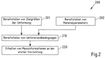
- Fig.2 shows a diagram of a method 200 for obtaining measurement information for a forming process to be carried out on a metal part, in particular for steel or aluminum forming.
- the method 200 is carried out by at least one first device 302.
- the first device 302 provides forming boundary conditions to the second device 304 in action 210.
- the forming boundary conditions can optionally include target variables and/or material parameters. Accordingly, target variables can be provided with action 201 or material parameters with action 202.
- the measurement information provided by the second device 304 is obtained at the first device 302, which is based at least partially on the forming boundary conditions and on material parameters of the metal part and/or process parameters of the forming process to be carried out.
- Fig.3 shows a schematic representation of a system 300 according to the third teaching, wherein the system 300 comprises a first device 302 which is associated with a consumer and a second device 304 which is associated with a manufacturer.
- the customer can use the first device 302 to provide forming boundary conditions and send them to the second device 304 for transmission 306, the transmission 306 being secure.
- the second device 304 can query a distribution of material parameters from a database 308, to which, for example, only the manufacturer has access.
- the second device 304 can trigger forming simulations to be carried out on the basis of the forming boundary conditions and the distribution of material parameters on a system 310 of third devices, which, for example, provide computing capacity for forming simulations.
- Measurement information is provided, and the measurement information can be transmitted 312 to the first device 302.
- the at least one first device in particular further comprises a forming device (not shown), wherein a forming of a metal part can be carried out taking the forming results into account.
- Fig.4 shows a block diagram of an embodiment of a device 400, which can in particular carry out an exemplary method according to the first teaching and/or method for obtaining measurement information.
- the device 400 is, for example, a device according to the second teaching or a system according to the third teaching.
- the device 400 can thus be, for example, a computer, a desktop computer, a server, a server farm, a cloud, a thin client or a portable computer (mobile device), such as a laptop computer, a tablet computer, a personal digital assistant (PDA) or a smartphone.
- the device can, for example, fulfill the function of a server or a client.
- Processor 410 of device 400 is designed in particular as a microprocessor, microcontrol unit, microcontroller, digital signal processor (DSP), application-specific integrated circuit (ASIC) or field programmable gate array (FPGA).
- DSP digital signal processor
- ASIC application-specific integrated circuit
- FPGA field programmable gate array
- Processor 410 executes program instructions stored in program memory 412 and stores, for example, intermediate results or the like in working or main memory 411.
- program memory 412 is a non-volatile memory such as a flash memory, a magnetic memory, an EEPROM (electrically erasable programmable read-only memory) and/or an optical memory.
- Main memory 411 is, for example, a volatile or non-volatile memory, in particular a random access memory (RAM) such as a static random access memory (SRAM), a dynamic random access memory (DRAM), a ferroelectric random access memory (FeRAM) and/or a magnetic random access memory (MRAM).
- RAM random access memory
- SRAM static random access memory
- DRAM dynamic random access memory
- FeRAM ferroelectric random access memory
- MRAM magnetic random access memory
- Program memory 412 is preferably a local data carrier that is permanently connected to the device 400.
- Data carriers that are permanently connected to the device 400 are, for example, hard disks that are built into the device 400.
- the data carrier can also be, for example, a detachably connectable to the device 400. It can be a storage device such as a memory stick, a removable storage device, a portable hard drive, a CD, a DVD and/or a floppy disk.
- Program memory 412 contains, for example, the operating system of device 400, which is at least partially loaded into main memory 411 and executed by processor 410 upon startup of device 400. In particular, upon startup of device 400, at least a portion of the core of the operating system is loaded into main memory 411 and executed by processor 410.
- the operating system of device 400 is, for example, a Windows, UNIX, Linux, Android, Apple iOS and/or MAC operating system.
- the operating system enables in particular the use of the device 400 for data processing.
- it manages resources such as main memory 411 and program memory 412, network interface 413, input and output device 414, provides basic functions to other programs through programming interfaces, among other things, and controls the execution of programs.
- Processor 410 controls the communication interface 413, which can be a network interface, for example, and can be designed as a network card, network module, and/or modem.
- the communication interface 413 is designed in particular to establish a connection of the device 400 to other devices, in particular via a (wireless) communication system, for example a network, and to communicate with them.
- the communication interface 413 can, for example, receive data (via the communication system) and forward it to processor 410 and/or receive data from processor 410 and send it (via the communication system).
- Examples of a communication system are a local area network (LAN), a wide area network (WAN), a wireless network (for example according to the IEEE 802.11 standard, the Bluetooth (LE) standard, and/or the NFC standard), a wired network, a cellular network, a telephone network, and/or the Internet.
- LAN local area network
- WAN wide area network
- wireless network for example according to the IEEE 802.11 standard, the Bluetooth (LE) standard, and/or the NFC standard
- wired network for example according to the IEEE 802.11 standard, the Bluetooth (LE) standard, and/or the NFC standard
- processor 410 can control at least one input/output device 414.
- Input/output device 414 is, for example, a keyboard, a mouse, a display unit, a microphone, a touch-sensitive display unit, a loudspeaker, a reader, a drive and/or a camera.
- Input/output device 414 can, for example, receive inputs from a user and forward them to processor 410 and/or receive and output information for the user from processor 410.
- Fig.5 finally shows different embodiments of storage media on which an embodiment of a computer program according to the invention can be stored.
- the storage medium can be, for example, a magnetic, electrical, optical and/or other type of storage medium.
- the storage medium can, for example, be part of a processor (eg the processor 410 of the Fig.4 ), for example a (non-volatile or volatile) program memory of the processor or a part thereof (such as program memory 412 in Fig.4 ).
- Embodiments of a storage medium are a flash memory 510, an SSD hard disk 511, a magnetic hard disk 512, a memory card 513, a memory stick 514 (e.g. a USB stick), a CD-ROM or DVD 515 or a floppy disk 516.
- a flash memory 510 an SSD hard disk 511, a magnetic hard disk 512, a memory card 513, a memory stick 514 (e.g. a USB stick), a CD-ROM or DVD 515 or a floppy disk 516.
Landscapes
- Engineering & Computer Science (AREA)
- Physics & Mathematics (AREA)
- General Physics & Mathematics (AREA)
- Theoretical Computer Science (AREA)
- Computer Hardware Design (AREA)
- Automation & Control Theory (AREA)
- Manufacturing & Machinery (AREA)
- Evolutionary Computation (AREA)
- Geometry (AREA)
- General Engineering & Computer Science (AREA)
- Human Computer Interaction (AREA)
- Shaping Metal By Deep-Drawing, Or The Like (AREA)
- General Factory Administration (AREA)
Claims (11)
- Procédé de détermination d'informations de mesure pour un formage à effectuer d'une pièce métallique, en particulier pour le formage de l'acier ou de l'aluminium, le procédé étant mis en oeuvre par au moins un deuxième dispositif (304), le procédé comprenant :- l'obtention (110) de conditions de bord de formage du formage à effectuer à partir d'un premier dispositif (302) sur le second dispositif (304) ;- Obtention et/ou détermination de paramètres de matériau de la pièce métallique et/ou de paramètres de processus du formage à effectuer ;- l'exécution et/ou le déclenchement de l'exécution (130) d'au moins une simulation de formage sur la base des conditions de bord de formage et des paramètres de matériau et/ou des paramètres de processus ; caractérisé en outre par- déterminer (140) des informations de mesure basées au moins en partie sur ladite au moins une simulation de formage, lesdites informations de mesure étant- comprennent des informations sur les grandeurs de mesure indicatives d'une ou de plusieurs grandeurs de mesure à déterminer lors de la transformation à effectuer et/ou- comprennent des informations de position de mesure indicatives d'une ou plusieurs positions d'un ou plusieurs capteurs à utiliser dans la déformation à effectuer et/ou- indiquer le type d'enregistrement à utiliser, et/ou- indiquer une date prévisionnelle à laquelle une mesure spécifique doit être effectuée ; et- fournir (150) les informations de mesure du second dispositif au premier dispositif.
- Procédé selon la revendication 1, comprenant :- l'obtention et/ou la détermination (120) d'une répartition de paramètres de matériau de la pièce métallique et/ou de paramètres de processus du formage à effectuer,- dans lequel l'exécution et/ou le déclenchement de l'exécution de ladite au moins une simulation de formage est basée sur les conditions de bord de formage et la distribution de paramètres de matériau et/ou de paramètres de processus.
- Procédé selon la revendication 1 ou 2, comprenant :- la détermination (131) d'un ou de plusieurs points critiques sur une pièce métallique et/ou d'un ou de plusieurs moments critiques pendant le formage à effectuer, la détermination d'informations de mesure étant en outre basée sur le ou les points critiques déterminés et/ou le ou les moments critiques.
- Procédé selon l'une quelconque des revendications 1 à 3, dans lequel les conditions de bord de formage comprennent au moins partiellement les variables cibles du formage, comprenant :- déterminer (132) une dépendance entre des grandeurs cibles d'une part et des paramètres de matériau et/ou des paramètres de processus d'autre part à l'aide de la simulation de formage ou des simulations de formage,la détermination d'informations de mesure étant en outre basée sur la dépendance de grandeurs cibles et de paramètres de matériau et/ou de paramètres de processus.
- Procédé selon la revendication 4, comprenant :- déterminer (133) une dépendance fonctionnelle, en particulier une corrélation, entre des grandeurs cibles et/ou des paramètres de matériau et/ou des paramètres de processus,la détermination des informations de mesure étant en outre basée au moins en partie sur la dépendance fonctionnelle, notamment la corrélation, entre des grandeurs cibles et/ou des paramètres de matériau et/ou des paramètres de processus.
- Procédé selon la revendication 4 ou 5, comprenant :- détermination d'informations de mesure, en particulier d'informations de grandeurs de mesure et/ou d'informations de positions de mesure indicatives d'écarts de résultats de formage, basés au moins partiellement sur la au moins une simulation de formage, par rapport aux grandeurs cibles dans des positions autres que des positions d'une pièce métallique à fabriquer indiquées par l'information de position de mesure.
- Procédé selon l'une quelconque des revendications 1 à 6,- Exécuter et/ou déclencher l'exécution d'une ou plusieurs simulations d e formage sur la base des conditions de bord de formage et des informations de mesure.- Détermination des résultats de formage à titre indicatif pour une sécurité de processus attendue.
- Procédé selon l'une quelconque des revendications 1 à 7, dans lequel les conditions de bord de formage comprennent au moins partiellement les paramètres de matériau.
- Procédé selon l'une quelconque des revendications 1 à 8, comprenant:- la détermination d'une efficacité des informations de mesure ;- dans lequel l'efficacité des informations de mesure est prise en compte lors de la fourniture des informations de mesure par le second dispositif au premier dispositif.
- Dispositif agencé ou comprenant des moyens correspondants pour exécuter et/ou commander un procédé selon l'une des revendications précédentes.
- Système comprenant une pluralité de dispositifs (302, 304, 310) qui exécutent ensemble un procédé selon l'une quelconque des revendications de procédé précédentes.
Applications Claiming Priority (2)
| Application Number | Priority Date | Filing Date | Title |
|---|---|---|---|
| DE102018121198.8A DE102018121198A1 (de) | 2018-08-30 | 2018-08-30 | Verfahren, Vorrichtung und System zur Ermittlung von Messinformationen |
| PCT/EP2019/063518 WO2020043335A1 (fr) | 2018-08-30 | 2019-05-24 | Procédé, dispositif et système pour déterminer des informations de mesure |
Publications (2)
| Publication Number | Publication Date |
|---|---|
| EP3844579A1 EP3844579A1 (fr) | 2021-07-07 |
| EP3844579B1 true EP3844579B1 (fr) | 2024-07-17 |
Family
ID=66752058
Family Applications (1)
| Application Number | Title | Priority Date | Filing Date |
|---|---|---|---|
| EP19728345.0A Active EP3844579B1 (fr) | 2018-08-30 | 2019-05-24 | Procédé, dispositif et système pour déterminer des informations de mesure |
Country Status (3)
| Country | Link |
|---|---|
| EP (1) | EP3844579B1 (fr) |
| DE (1) | DE102018121198A1 (fr) |
| WO (1) | WO2020043335A1 (fr) |
Families Citing this family (3)
| Publication number | Priority date | Publication date | Assignee | Title |
|---|---|---|---|---|
| CN111783338B (zh) * | 2020-06-30 | 2023-04-21 | 平安国际智慧城市科技股份有限公司 | 基于人工智能的微观组织金属强度分布预测方法及装置 |
| DE102021121991B4 (de) | 2021-08-25 | 2025-11-13 | Bayerische Motoren Werke Aktiengesellschaft | Verfahren zum Bestimmen eines Betriebsparameters eines Werkzeugs zum Formen von Bauteilen in einer Presse |
| EP4375774A1 (fr) * | 2022-11-28 | 2024-05-29 | Siemens Aktiengesellschaft | Procédé et dispositif de détermination de paramètres de processus |
Family Cites Families (7)
| Publication number | Priority date | Publication date | Assignee | Title |
|---|---|---|---|---|
| US6353768B1 (en) * | 1998-02-02 | 2002-03-05 | General Electric Company | Method and apparatus for designing a manufacturing process for sheet metal parts |
| JP4418141B2 (ja) * | 2001-05-16 | 2010-02-17 | 新日本製鐵株式会社 | 材料データ提供システム |
| US8046098B2 (en) * | 2007-01-08 | 2011-10-25 | Jeom Kee Paik | Curved surface forming method of a metal plate |
| US8560103B2 (en) * | 2010-11-17 | 2013-10-15 | Waldemar Kubli | Method and computing system for designing a sheet-metal-forming process |
| EP2463792B1 (fr) * | 2010-11-17 | 2020-01-08 | Autoform Engineering GmbH | Procédé et système pour traiter et afficher des paramètres de simulation de l'emboutissage de tôles métalliques |
| CN106140901A (zh) * | 2015-03-31 | 2016-11-23 | 株式会社日立制作所 | 金属板材弯曲成形控制方法 |
| DE102016108163B4 (de) * | 2016-05-03 | 2025-01-23 | Bayerische Motoren Werke Aktiengesellschaft | Verfahren und Vorrichtung zum Bestimmen einer Qualität eines in einem Umformvorgang umgeformten Bauteils |
-
2018
- 2018-08-30 DE DE102018121198.8A patent/DE102018121198A1/de not_active Withdrawn
-
2019
- 2019-05-24 WO PCT/EP2019/063518 patent/WO2020043335A1/fr not_active Ceased
- 2019-05-24 EP EP19728345.0A patent/EP3844579B1/fr active Active
Also Published As
| Publication number | Publication date |
|---|---|
| EP3844579A1 (fr) | 2021-07-07 |
| WO2020043335A1 (fr) | 2020-03-05 |
| DE102018121198A1 (de) | 2020-03-05 |
Similar Documents
| Publication | Publication Date | Title |
|---|---|---|
| EP4217806B1 (fr) | Contrôle qualité pour produits fabriqués en série | |
| EP3844579B1 (fr) | Procédé, dispositif et système pour déterminer des informations de mesure | |
| EP4108411B1 (fr) | Procédé, système et produit de programme informatique permettant de surveiller un processus de formage | |
| DE112018007712B4 (de) | Datenverarbeitungseinrichtung und datenverarbeitungsverfahren | |
| EP1623287B1 (fr) | Conception d'outils et de processus pour technique de formage | |
| DE102022202366A1 (de) | Umgebungstemperaturänderungvorhersagevorrichtung und Vorhersageverfahren für eine Werkzeugmaschine | |
| DE112019005467T5 (de) | System und verfahren zum erkennen und vorhersagen von mustern eines anomalen sensorverhaltens einer maschine | |
| EP4435690A2 (fr) | Procédé de traitement, serveur de base de données, système et procédé de partage de données pour des dispositifs de traitement au moyen d'une transmission de données à distance | |
| EP2433185B1 (fr) | Dispositif et procédé pour le traitement d'une base de données de simulation d'un processus | |
| WO2020120439A1 (fr) | Procédé pour déterminer des résultats de formage à chaud de tôles métalliques et procédé de formage à chaud de tôles | |
| DE102020215136A1 (de) | Verfahren zur automatisierten Bewertung eines Simulationsmodells | |
| EP3942372B1 (fr) | Procédé de validation de paramètres de système d'un système énergétique, procédé pour faire fonctionner un système énergétique et système de gestion d'énergie pour un système énergétique | |
| EP1264253B1 (fr) | Procede et dispositif pour la modelisation d'un systeme | |
| DE102018108575B4 (de) | Verfahren zur Ermittlung von Umformergebnissen von Metallteilen sowie Vorrichtung und System | |
| DE102020200849A1 (de) | Verfahren und Vorrichtung zur Prozessoptimierung einer Fertigungsprozesskette | |
| WO2024156387A1 (fr) | Procédé de surveillance d'un système d'automatisation | |
| DE102007039441A1 (de) | Verfahren und System zur Überwachung von Computern | |
| DE102019220453A1 (de) | Verfahren und Vorrichtung zum Erstellen einer Sicherheitsfunktion für das Vermessen eines Fertigungssystems | |
| DE102019107409A1 (de) | Robustheitsanalyse bei Umformprozessen | |
| EP2137622B1 (fr) | Procédé et système de traitement de données pour l'analyse de performance assistée par ordinateur d'un système de traitement de données | |
| EP4254109B1 (fr) | Évaluation de l'état d'un système | |
| DE102023108526A1 (de) | Verfahren zum erkennen von änderungen in einer datenbank | |
| DE112021008086B4 (de) | Zustandserfassungssystem, zustandserfassungsverfahren und zustandserfassungsprogramm | |
| DE102024128971A1 (de) | Verfahren zur Mensch-Maschine-Interaktion mit Validierung | |
| DE112023004218T5 (de) | Lerngerät, Vorausberechnungsgerät, Diagnosegerät, Diagnosesystem, Modellerzeugungsverfahren, Vorausberechnungsverfahren, Diagnoseverfahren und Programm |
Legal Events
| Date | Code | Title | Description |
|---|---|---|---|
| STAA | Information on the status of an ep patent application or granted ep patent |
Free format text: STATUS: UNKNOWN |
|
| STAA | Information on the status of an ep patent application or granted ep patent |
Free format text: STATUS: THE INTERNATIONAL PUBLICATION HAS BEEN MADE |
|
| STAA | Information on the status of an ep patent application or granted ep patent |
Free format text: STATUS: REQUEST FOR EXAMINATION WAS MADE |
|
| PUAI | Public reference made under article 153(3) epc to a published international application that has entered the european phase |
Free format text: ORIGINAL CODE: 0009012 |
|
| 17P | Request for examination filed |
Effective date: 20210120 |
|
| AK | Designated contracting states |
Kind code of ref document: A1 Designated state(s): AL AT BE BG CH CY CZ DE DK EE ES FI FR GB GR HR HU IE IS IT LI LT LU LV MC MK MT NL NO PL PT RO RS SE SI SK SM TR |
|
| DAV | Request for validation of the european patent (deleted) | ||
| DAX | Request for extension of the european patent (deleted) | ||
| STAA | Information on the status of an ep patent application or granted ep patent |
Free format text: STATUS: EXAMINATION IS IN PROGRESS |
|
| 17Q | First examination report despatched |
Effective date: 20221202 |
|
| GRAP | Despatch of communication of intention to grant a patent |
Free format text: ORIGINAL CODE: EPIDOSNIGR1 |
|
| STAA | Information on the status of an ep patent application or granted ep patent |
Free format text: STATUS: GRANT OF PATENT IS INTENDED |
|
| RIC1 | Information provided on ipc code assigned before grant |
Ipc: G06F 113/24 20200101ALI20240207BHEP Ipc: G06F 111/08 20200101ALI20240207BHEP Ipc: G06F 30/23 20200101ALI20240207BHEP Ipc: G06F 30/00 20200101ALI20240207BHEP Ipc: G05B 19/4069 20060101AFI20240207BHEP |
|
| INTG | Intention to grant announced |
Effective date: 20240228 |
|
| GRAS | Grant fee paid |
Free format text: ORIGINAL CODE: EPIDOSNIGR3 |
|
| GRAA | (expected) grant |
Free format text: ORIGINAL CODE: 0009210 |
|
| STAA | Information on the status of an ep patent application or granted ep patent |
Free format text: STATUS: THE PATENT HAS BEEN GRANTED |
|
| AK | Designated contracting states |
Kind code of ref document: B1 Designated state(s): AL AT BE BG CH CY CZ DE DK EE ES FI FR GB GR HR HU IE IS IT LI LT LU LV MC MK MT NL NO PL PT RO RS SE SI SK SM TR |
|
| REG | Reference to a national code |
Ref country code: CH Ref legal event code: EP |
|
| REG | Reference to a national code |
Ref country code: DE Ref legal event code: R096 Ref document number: 502019011702 Country of ref document: DE |
|
| REG | Reference to a national code |
Ref country code: DE Ref legal event code: R084 Ref document number: 502019011702 Country of ref document: DE |
|
| REG | Reference to a national code |
Ref country code: IE Ref legal event code: FG4D Free format text: LANGUAGE OF EP DOCUMENT: GERMAN |
|
| P01 | Opt-out of the competence of the unified patent court (upc) registered |
Free format text: CASE NUMBER: APP_41177/2024 Effective date: 20240711 |
|
| REG | Reference to a national code |
Ref country code: LT Ref legal event code: MG9D |
|
| REG | Reference to a national code |
Ref country code: NL Ref legal event code: MP Effective date: 20240717 |
|
| PG25 | Lapsed in a contracting state [announced via postgrant information from national office to epo] |
Ref country code: PT Free format text: LAPSE BECAUSE OF FAILURE TO SUBMIT A TRANSLATION OF THE DESCRIPTION OR TO PAY THE FEE WITHIN THE PRESCRIBED TIME-LIMIT Effective date: 20241118 |
|
| PG25 | Lapsed in a contracting state [announced via postgrant information from national office to epo] |
Ref country code: NL Free format text: LAPSE BECAUSE OF FAILURE TO SUBMIT A TRANSLATION OF THE DESCRIPTION OR TO PAY THE FEE WITHIN THE PRESCRIBED TIME-LIMIT Effective date: 20240717 |
|
| PG25 | Lapsed in a contracting state [announced via postgrant information from national office to epo] |
Ref country code: PT Free format text: LAPSE BECAUSE OF FAILURE TO SUBMIT A TRANSLATION OF THE DESCRIPTION OR TO PAY THE FEE WITHIN THE PRESCRIBED TIME-LIMIT Effective date: 20241118 Ref country code: NL Free format text: LAPSE BECAUSE OF FAILURE TO SUBMIT A TRANSLATION OF THE DESCRIPTION OR TO PAY THE FEE WITHIN THE PRESCRIBED TIME-LIMIT Effective date: 20240717 |
|
| PG25 | Lapsed in a contracting state [announced via postgrant information from national office to epo] |
Ref country code: NO Free format text: LAPSE BECAUSE OF FAILURE TO SUBMIT A TRANSLATION OF THE DESCRIPTION OR TO PAY THE FEE WITHIN THE PRESCRIBED TIME-LIMIT Effective date: 20241017 |
|
| PG25 | Lapsed in a contracting state [announced via postgrant information from national office to epo] |
Ref country code: GR Free format text: LAPSE BECAUSE OF FAILURE TO SUBMIT A TRANSLATION OF THE DESCRIPTION OR TO PAY THE FEE WITHIN THE PRESCRIBED TIME-LIMIT Effective date: 20241018 Ref country code: FI Free format text: LAPSE BECAUSE OF FAILURE TO SUBMIT A TRANSLATION OF THE DESCRIPTION OR TO PAY THE FEE WITHIN THE PRESCRIBED TIME-LIMIT Effective date: 20240717 Ref country code: PL Free format text: LAPSE BECAUSE OF FAILURE TO SUBMIT A TRANSLATION OF THE DESCRIPTION OR TO PAY THE FEE WITHIN THE PRESCRIBED TIME-LIMIT Effective date: 20240717 |
|
| PG25 | Lapsed in a contracting state [announced via postgrant information from national office to epo] |
Ref country code: BG Free format text: LAPSE BECAUSE OF FAILURE TO SUBMIT A TRANSLATION OF THE DESCRIPTION OR TO PAY THE FEE WITHIN THE PRESCRIBED TIME-LIMIT Effective date: 20240717 |
|
| PG25 | Lapsed in a contracting state [announced via postgrant information from national office to epo] |
Ref country code: LV Free format text: LAPSE BECAUSE OF FAILURE TO SUBMIT A TRANSLATION OF THE DESCRIPTION OR TO PAY THE FEE WITHIN THE PRESCRIBED TIME-LIMIT Effective date: 20240717 |
|
| PG25 | Lapsed in a contracting state [announced via postgrant information from national office to epo] |
Ref country code: IS Free format text: LAPSE BECAUSE OF FAILURE TO SUBMIT A TRANSLATION OF THE DESCRIPTION OR TO PAY THE FEE WITHIN THE PRESCRIBED TIME-LIMIT Effective date: 20241117 |
|
| PG25 | Lapsed in a contracting state [announced via postgrant information from national office to epo] |
Ref country code: HR Free format text: LAPSE BECAUSE OF FAILURE TO SUBMIT A TRANSLATION OF THE DESCRIPTION OR TO PAY THE FEE WITHIN THE PRESCRIBED TIME-LIMIT Effective date: 20240717 |
|
| PG25 | Lapsed in a contracting state [announced via postgrant information from national office to epo] |
Ref country code: ES Free format text: LAPSE BECAUSE OF FAILURE TO SUBMIT A TRANSLATION OF THE DESCRIPTION OR TO PAY THE FEE WITHIN THE PRESCRIBED TIME-LIMIT Effective date: 20240717 Ref country code: RS Free format text: LAPSE BECAUSE OF FAILURE TO SUBMIT A TRANSLATION OF THE DESCRIPTION OR TO PAY THE FEE WITHIN THE PRESCRIBED TIME-LIMIT Effective date: 20241017 |
|
| PG25 | Lapsed in a contracting state [announced via postgrant information from national office to epo] |
Ref country code: RS Free format text: LAPSE BECAUSE OF FAILURE TO SUBMIT A TRANSLATION OF THE DESCRIPTION OR TO PAY THE FEE WITHIN THE PRESCRIBED TIME-LIMIT Effective date: 20241017 Ref country code: PL Free format text: LAPSE BECAUSE OF FAILURE TO SUBMIT A TRANSLATION OF THE DESCRIPTION OR TO PAY THE FEE WITHIN THE PRESCRIBED TIME-LIMIT Effective date: 20240717 Ref country code: NO Free format text: LAPSE BECAUSE OF FAILURE TO SUBMIT A TRANSLATION OF THE DESCRIPTION OR TO PAY THE FEE WITHIN THE PRESCRIBED TIME-LIMIT Effective date: 20241017 Ref country code: LV Free format text: LAPSE BECAUSE OF FAILURE TO SUBMIT A TRANSLATION OF THE DESCRIPTION OR TO PAY THE FEE WITHIN THE PRESCRIBED TIME-LIMIT Effective date: 20240717 Ref country code: IS Free format text: LAPSE BECAUSE OF FAILURE TO SUBMIT A TRANSLATION OF THE DESCRIPTION OR TO PAY THE FEE WITHIN THE PRESCRIBED TIME-LIMIT Effective date: 20241117 Ref country code: HR Free format text: LAPSE BECAUSE OF FAILURE TO SUBMIT A TRANSLATION OF THE DESCRIPTION OR TO PAY THE FEE WITHIN THE PRESCRIBED TIME-LIMIT Effective date: 20240717 Ref country code: GR Free format text: LAPSE BECAUSE OF FAILURE TO SUBMIT A TRANSLATION OF THE DESCRIPTION OR TO PAY THE FEE WITHIN THE PRESCRIBED TIME-LIMIT Effective date: 20241018 Ref country code: FI Free format text: LAPSE BECAUSE OF FAILURE TO SUBMIT A TRANSLATION OF THE DESCRIPTION OR TO PAY THE FEE WITHIN THE PRESCRIBED TIME-LIMIT Effective date: 20240717 Ref country code: ES Free format text: LAPSE BECAUSE OF FAILURE TO SUBMIT A TRANSLATION OF THE DESCRIPTION OR TO PAY THE FEE WITHIN THE PRESCRIBED TIME-LIMIT Effective date: 20240717 Ref country code: BG Free format text: LAPSE BECAUSE OF FAILURE TO SUBMIT A TRANSLATION OF THE DESCRIPTION OR TO PAY THE FEE WITHIN THE PRESCRIBED TIME-LIMIT Effective date: 20240717 |
|
| PG25 | Lapsed in a contracting state [announced via postgrant information from national office to epo] |
Ref country code: DK Free format text: LAPSE BECAUSE OF FAILURE TO SUBMIT A TRANSLATION OF THE DESCRIPTION OR TO PAY THE FEE WITHIN THE PRESCRIBED TIME-LIMIT Effective date: 20240717 Ref country code: SM Free format text: LAPSE BECAUSE OF FAILURE TO SUBMIT A TRANSLATION OF THE DESCRIPTION OR TO PAY THE FEE WITHIN THE PRESCRIBED TIME-LIMIT Effective date: 20240717 Ref country code: RO Free format text: LAPSE BECAUSE OF FAILURE TO SUBMIT A TRANSLATION OF THE DESCRIPTION OR TO PAY THE FEE WITHIN THE PRESCRIBED TIME-LIMIT Effective date: 20240717 |
|
| REG | Reference to a national code |
Ref country code: DE Ref legal event code: R097 Ref document number: 502019011702 Country of ref document: DE |
|
| PG25 | Lapsed in a contracting state [announced via postgrant information from national office to epo] |
Ref country code: EE Free format text: LAPSE BECAUSE OF FAILURE TO SUBMIT A TRANSLATION OF THE DESCRIPTION OR TO PAY THE FEE WITHIN THE PRESCRIBED TIME-LIMIT Effective date: 20240717 |
|
| PG25 | Lapsed in a contracting state [announced via postgrant information from national office to epo] |
Ref country code: CZ Free format text: LAPSE BECAUSE OF FAILURE TO SUBMIT A TRANSLATION OF THE DESCRIPTION OR TO PAY THE FEE WITHIN THE PRESCRIBED TIME-LIMIT Effective date: 20240717 |
|
| PG25 | Lapsed in a contracting state [announced via postgrant information from national office to epo] |
Ref country code: SK Free format text: LAPSE BECAUSE OF FAILURE TO SUBMIT A TRANSLATION OF THE DESCRIPTION OR TO PAY THE FEE WITHIN THE PRESCRIBED TIME-LIMIT Effective date: 20240717 |
|
| PLBE | No opposition filed within time limit |
Free format text: ORIGINAL CODE: 0009261 |
|
| STAA | Information on the status of an ep patent application or granted ep patent |
Free format text: STATUS: NO OPPOSITION FILED WITHIN TIME LIMIT |
|
| 26N | No opposition filed |
Effective date: 20250422 |
|
| PGFP | Annual fee paid to national office [announced via postgrant information from national office to epo] |
Ref country code: DE Payment date: 20250521 Year of fee payment: 7 |
|
| PG25 | Lapsed in a contracting state [announced via postgrant information from national office to epo] |
Ref country code: SE Free format text: LAPSE BECAUSE OF FAILURE TO SUBMIT A TRANSLATION OF THE DESCRIPTION OR TO PAY THE FEE WITHIN THE PRESCRIBED TIME-LIMIT Effective date: 20240717 |
|
| REG | Reference to a national code |
Ref country code: CH Ref legal event code: H13 Free format text: ST27 STATUS EVENT CODE: U-0-0-H10-H13 (AS PROVIDED BY THE NATIONAL OFFICE) Effective date: 20251223 |
|
| PG25 | Lapsed in a contracting state [announced via postgrant information from national office to epo] |
Ref country code: LU Free format text: LAPSE BECAUSE OF NON-PAYMENT OF DUE FEES Effective date: 20250524 |
|
| PG25 | Lapsed in a contracting state [announced via postgrant information from national office to epo] |
Ref country code: CH Free format text: LAPSE BECAUSE OF NON-PAYMENT OF DUE FEES Effective date: 20250531 |
|
| GBPC | Gb: european patent ceased through non-payment of renewal fee |
Effective date: 20250524 |
|
| PG25 | Lapsed in a contracting state [announced via postgrant information from national office to epo] |
Ref country code: IT Free format text: LAPSE BECAUSE OF FAILURE TO SUBMIT A TRANSLATION OF THE DESCRIPTION OR TO PAY THE FEE WITHIN THE PRESCRIBED TIME-LIMIT Effective date: 20240717 |
|
| REG | Reference to a national code |
Ref country code: BE Ref legal event code: MM Effective date: 20250531 |
|
| PG25 | Lapsed in a contracting state [announced via postgrant information from national office to epo] |
Ref country code: MC Free format text: LAPSE BECAUSE OF FAILURE TO SUBMIT A TRANSLATION OF THE DESCRIPTION OR TO PAY THE FEE WITHIN THE PRESCRIBED TIME-LIMIT Effective date: 20240717 |
|
| REG | Reference to a national code |
Ref country code: DE Ref legal event code: R081 Ref document number: 502019011702 Country of ref document: DE Owner name: THYSSENKRUPP STEEL EUROPE AG, DE Free format text: FORMER OWNERS: THYSSENKRUPP AG, 45143 ESSEN, DE; THYSSENKRUPP STEEL EUROPE AG, 47166 DUISBURG, DE |
|
| PG25 | Lapsed in a contracting state [announced via postgrant information from national office to epo] |
Ref country code: GB Free format text: LAPSE BECAUSE OF NON-PAYMENT OF DUE FEES Effective date: 20250524 |
|
| PG25 | Lapsed in a contracting state [announced via postgrant information from national office to epo] |
Ref country code: IE Free format text: LAPSE BECAUSE OF NON-PAYMENT OF DUE FEES Effective date: 20250524 |
|
| PG25 | Lapsed in a contracting state [announced via postgrant information from national office to epo] |
Ref country code: BE Free format text: LAPSE BECAUSE OF NON-PAYMENT OF DUE FEES Effective date: 20250531 |
|
| PG25 | Lapsed in a contracting state [announced via postgrant information from national office to epo] |
Ref country code: FR Free format text: LAPSE BECAUSE OF NON-PAYMENT OF DUE FEES Effective date: 20250531 |