EP3844581B1 - Verfahren zum erreichen der verfolgbarkeit eines werkzeugbetriebs - Google Patents
Verfahren zum erreichen der verfolgbarkeit eines werkzeugbetriebs Download PDFInfo
- Publication number
- EP3844581B1 EP3844581B1 EP19790318.0A EP19790318A EP3844581B1 EP 3844581 B1 EP3844581 B1 EP 3844581B1 EP 19790318 A EP19790318 A EP 19790318A EP 3844581 B1 EP3844581 B1 EP 3844581B1
- Authority
- EP
- European Patent Office
- Prior art keywords
- tool
- base station
- data
- mrr
- free space
- Prior art date
- Legal status (The legal status is an assumption and is not a legal conclusion. Google has not performed a legal analysis and makes no representation as to the accuracy of the status listed.)
- Active
Links
Images

Classifications
-
- G—PHYSICS
- G05—CONTROLLING; REGULATING
- G05B—CONTROL OR REGULATING SYSTEMS IN GENERAL; FUNCTIONAL ELEMENTS OF SUCH SYSTEMS; MONITORING OR TESTING ARRANGEMENTS FOR SUCH SYSTEMS OR ELEMENTS
- G05B19/00—Program-control systems
- G05B19/02—Program-control systems electric
- G05B19/418—Total factory control, i.e. centrally controlling a plurality of machines, e.g. direct or distributed numerical control [DNC], flexible manufacturing systems [FMS], integrated manufacturing systems [IMS] or computer integrated manufacturing [CIM]
-
- H—ELECTRICITY
- H04—ELECTRIC COMMUNICATION TECHNIQUE
- H04B—TRANSMISSION
- H04B10/00—Transmission systems employing electromagnetic waves other than radio-waves, e.g. infrared, visible or ultraviolet light, or employing corpuscular radiation, e.g. quantum communication
- H04B10/11—Arrangements specific to free-space transmission, i.e. transmission through air or vacuum
- H04B10/114—Indoor or close-range type systems
- H04B10/1149—Arrangements for indoor wireless networking of information
-
- G—PHYSICS
- G01—MEASURING; TESTING
- G01S—RADIO DIRECTION-FINDING; RADIO NAVIGATION; DETERMINING DISTANCE OR VELOCITY BY USE OF RADIO WAVES; LOCATING OR PRESENCE-DETECTING BY USE OF THE REFLECTION OR RERADIATION OF RADIO WAVES; ANALOGOUS ARRANGEMENTS USING OTHER WAVES
- G01S17/00—Systems using the reflection or reradiation of electromagnetic waves other than radio waves, e.g. lidar systems
- G01S17/02—Systems using the reflection of electromagnetic waves other than radio waves
- G01S17/06—Systems determining position data of a target
- G01S17/08—Systems determining position data of a target for measuring distance only
-
- G—PHYSICS
- G01—MEASURING; TESTING
- G01S—RADIO DIRECTION-FINDING; RADIO NAVIGATION; DETERMINING DISTANCE OR VELOCITY BY USE OF RADIO WAVES; LOCATING OR PRESENCE-DETECTING BY USE OF THE REFLECTION OR RERADIATION OF RADIO WAVES; ANALOGOUS ARRANGEMENTS USING OTHER WAVES
- G01S17/00—Systems using the reflection or reradiation of electromagnetic waves other than radio waves, e.g. lidar systems
- G01S17/66—Tracking systems using electromagnetic waves other than radio waves
-
- G—PHYSICS
- G08—SIGNALLING
- G08C—TRANSMISSION SYSTEMS FOR MEASURED VALUES, CONTROL OR SIMILAR SIGNALS
- G08C23/00—Non-electrical signal transmission systems, e.g. optical systems
- G08C23/04—Non-electrical signal transmission systems, e.g. optical systems using light waves, e.g. infrared
-
- H—ELECTRICITY
- H04—ELECTRIC COMMUNICATION TECHNIQUE
- H04B—TRANSMISSION
- H04B10/00—Transmission systems employing electromagnetic waves other than radio-waves, e.g. infrared, visible or ultraviolet light, or employing corpuscular radiation, e.g. quantum communication
- H04B10/11—Arrangements specific to free-space transmission, i.e. transmission through air or vacuum
- H04B10/114—Indoor or close-range type systems
- H04B10/1143—Bidirectional transmission
-
- G—PHYSICS
- G01—MEASURING; TESTING
- G01B—MEASURING LENGTH, THICKNESS OR SIMILAR LINEAR DIMENSIONS; MEASURING ANGLES; MEASURING AREAS; MEASURING IRREGULARITIES OF SURFACES OR CONTOURS
- G01B11/00—Measuring arrangements characterised by the use of optical techniques
-
- G—PHYSICS
- G01—MEASURING; TESTING
- G01C—MEASURING DISTANCES, LEVELS OR BEARINGS; SURVEYING; NAVIGATION; GYROSCOPIC INSTRUMENTS; PHOTOGRAMMETRY OR VIDEOGRAMMETRY
- G01C1/00—Measuring angles
- G01C1/02—Theodolites
-
- Y—GENERAL TAGGING OF NEW TECHNOLOGICAL DEVELOPMENTS; GENERAL TAGGING OF CROSS-SECTIONAL TECHNOLOGIES SPANNING OVER SEVERAL SECTIONS OF THE IPC; TECHNICAL SUBJECTS COVERED BY FORMER USPC CROSS-REFERENCE ART COLLECTIONS [XRACs] AND DIGESTS
- Y02—TECHNOLOGIES OR APPLICATIONS FOR MITIGATION OR ADAPTATION AGAINST CLIMATE CHANGE
- Y02P—CLIMATE CHANGE MITIGATION TECHNOLOGIES IN THE PRODUCTION OR PROCESSING OF GOODS
- Y02P90/00—Enabling technologies with a potential contribution to greenhouse gas [GHG] emissions mitigation
- Y02P90/02—Total factory control, e.g. smart factories, flexible manufacturing systems [FMS] or integrated manufacturing systems [IMS]
Definitions
- the operations that are performed on the 'workpieces' are from various sorts, like pressing, welding, painting, assembling etc.
- an operation is performed by at least one special tool, designed to be capable of performing a specific task.
- tools are wrenches, fastening tools, riveting tools, paint nozzle tools, pressing tools, imprinting tools, stamping tools, drilling tools and others.
- the tools can be powered manually, electrically (from battery or mains) or pneumatically, as they perform their specific operations on workpieces.
- the tools can be handled manually, by a human operator, or by a machine or robot.
- High level of control is reached when using well designed and controllable tools for specific purposes, having capability of storing operational data, and maintaining a low level of ambiguity.
- a sub-concept to the level of control in production is the level of traceability, i.e. the ability to know in detail what operations have been done on a workpiece and when.
- a tool type that is commonly used in many different assembling production facilities, on many different applications, are power tools, so called 'nut runners', or 'fastening tools' where the actual operations are defined by fastening parts together via threaded joints.
- Such power tool system is known e.g. from D1: US 2002003043 (A1 ), which presents a portable electric power tool, connected via a power cable to an operation control device (controller).
- the controller constitutes an intelligent system that can be programmed for making the tool to behave in different ways.
- the controller In a large and advanced production facility where a tool system such as the one described in D1 is used, the controller also communicates with an upper level production system, partly to receive production data (also called 'build data') that defines the characteristic parameters for the tool settings adapted for the operation that the tool is about to perform. After an operation, result data is transferred from the tool's sensors, via the controller to the upper level production system for providing the desirable traceability regarding the performed operation.
- production data also called 'build data'
- result data is transferred from the tool's sensors, via the controller to the upper level production system for providing the desirable traceability regarding the performed operation.
- Another embodiment of the tool system in D1 is a tool powered by a battery and equipped with an embedded control device and thus no "wired" connection to external control devices, but still with capability to wirelessly communicate operational tool data with external devices and an upper level production system.
- the wireless communication technology is normally radio based, such as WLAN, Bluetooth, Zigbee etc.
- radio-frequency, hereinafter referred to as RF, based communication has had an enormous development the past decades considering the high quantities of communicating devices, and the number of such devices in the industrial world is expected to increase further, not least due to the concept of 'internet-of-things' (lOT) which has become a subject of interest for many companies.
- RF communication suffers from some problems which tend to increase as the number of RF communicating devices increases. Particularly in facilities where the radio traffic is dense, as in the environment of this invention, the problems of extensive use of RF communication can be discerned.
- Symptoms of the mentioned problems are among others an increasing number of interference issues between the many electronic devices in facilities that are commonly communicating via RF based technologies.
- the task to find available effective frequency channels and/or the obligation to apply for licenses regarding the use of certain RF channels sometimes implies time consuming and thus costly circumstances.
- the extensive use of RF communication according to the popular WLAN standard resulted in the introduction of the 5 GHz band, due to the limitations of the 2,4 GHz band. In that process, extra bandwidth was made available.
- the 5 GHz band is also not limitless.
- the use of higher RF communication frequencies implies increasing signal strengths, which in combination with an increasing number of communicating devices in general may be suspected to affect the working environment for human operators in facilities negatively.
- the disclosed invention aims to be a counter-measure to these challenges by using a non-RF based technology to focus on enabling data communication only when specific conditions are fulfilled. It states the importance of when and where data shall be interchanged, not just anytime and anywhere or 'as soon as possible'. Data communication related to traceability and control of tool operations is an example where such conditions can be stated. Traceability and control often require system knowledge of the whereabouts of the tool.
- D2 US 2016129569 (A1 ) presents a wireless tool system with a torque wrench that communicates wirelessly with another communication device.
- Data exchange may include parameter sets (production data) and the communication technology may be radio, such as zigbee.
- a wireless positioning system known in the art is e.g. the European patent D3: EP 3036067 (A1 ), which discloses a power tool system (e.g. as in D1) with a sender unit attached to the tool, sending identity signals that are picked up by receivers within the local area, and data processing means to use these signals for determining where in space the tool is located.
- the technology used in this system is based on the sending of ultra-wideband signals.
- One task for any tool positioning system is to identify parts or workpieces that shall be operated on. That could be done by marking them.
- One identifying marking method is already widely known in industrial applications since long time ago, and that consists of adding a label to a part which is readable by a reader.
- the label can consist of a OR code or a barcode etc.
- one technology used is data communication using Infra-Red (IR) light performed by IR scanners or similar.
- IR Infra-Red
- This label normally consists of information about the sub-part, such as the identity of it, type, colour or production batch etc. Normally, such a scanner is attached as an accessory to the tool or physically detached to it but still with capabilities to transfer the data to the tool system.
- the identity or any other information of the sub-part can be attached to the result data that after the operation is being sent to upper level system.
- the barcode information can be sent to upper level system as a first step where it is processed, before sending down proper production data that shall be used by the tool for the next operation as a second step.
- the tool is disabled before the label is scanned (i.e. it is not possible to perform operations with the tool) but enabled afterwards. In this way it is believed that the level of control is increased, even if it does not tell explicitly whether the operations are performed on the correct operation points or not.
- D4: DE 102006024904 (A1 ) is another document describing how the identity of a tool and additionally the identity of a storage location (where the tool resides) are retrieved by machine-readable identification techniques, conducted by a central computer.
- gyroscopes and accelerometer based electronic devices are also used in the art for following how a tool is moving in "free air" which thus provides a method to determine the location.
- a document that presents a system using an inertia measurements unit (IMU) as the main method for determining the position of a tool is D5: WO 2006059927 (A1 ).
- D5 it is mentioned that for accuracy reasons it is necessary to calibrate the inertial navigation system repeatedly, for example by placing the tool at a reference position.
- the reference point can be a fixed position relative to the working site, or alternatively, stationary relative to the production line.
- the calibration routine is exemplified by scanning a barcode on the object and simultaneously calibrate the inertia navigation system, where the barcode contains information about the object and said barcode is placed in a fixed position relative to the joints to be operated on, and the scanning is performed by a scanner mounted on the tool. Coordinates are stored together with the corresponding result data and since the physical distance relation between all operation points are known from CAD drawings etc., the system provides traceability as to which joints that are operated on.
- D6 US US2015253766 (A1 ) is a document describing a tool location system where a tool is equipped with a camera and the location of said tool is determined based on images from said camera.
- the overall environment of the invention is a manufacturing production facility where workpieces are worked upon in working sites by means of tools.
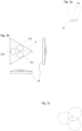
- Figure 1 shows the system setup of the invention in said working site:
- a workpiece (5) is to be worked upon by means of a tool (7), here held by a human operator (22), aiming to perform specific operations on specific operation points (6a, 6b, 6c).
- An upper level production system (1) is connected to a base station (10) via a network (2).
- Said base station (10) includes data processing means (3a), data memory means (3b) and furthermore a directional light source (4) such as a laser transmitting light of e.g. the near infrared and/or light in the visible spectrum.
- the light source (4) is preferably embedded in said base station (10) with Electronic Distance Measuring (EDM) means (31) and theodolite means (30) together with steering means (33) and a light sensor (32). If activating the tool trigger (29), the tool (7) performs an operation at its operation end (8) if said tool is configured to do so.
- the kind of operation that is performed can be of various sorts as the present invention is not limited to a certain type of tool operations. However, important is that said tool (7) contains at least one sensor for producing data that carries result information on the performed tool operation.
- Said tool also comprises processing means (28) and memory means (27).
- said base station (10) and said tool (7) have means for transferring data between each other via a Free Space Optical (FSO) communication link.
- a light source in the base station serves as the interrogating part and an MRR structure (9) on the tool (7) is the other part of said link.
- the light source being the interrogating part of the FSO communication link is preferably the same light source as the mentioned light source (4), as is described by fig. 1 and as is described in the following text, but it could also be another light source located close to it.
- One object of the present invention is to come to terms with interference related problems caused by extensive use of RF based data communication technologies in industrial environments such as between a mobile tool and stationary communication devices as in said system setup.
- data is interchanged only when specific conditions are fulfilled, and such conditions can be found in a working site as in the environment of the invention.
- a tool such as said tool (7) needs to report its operational result data to external devices after an operation, normally the sooner the better for an upper level production system (1) to have quickest possible updated status information on said tool operation.
- the tool needs to be programmed, or configured, with correct production data prior to an operation to perform said operation correctly.
- the verification of correct production data in said tool is preferably done as close in time before each operation as possible.
- the traceability and even the control of the tool operations are achieved through the very use of the FSO communication technique, as the sending and receiving of data occur only under very specific conditions, direction- and space -wise as well as timewise.
- FSO communication technology An ability of data communication via light, known as FSO communication technology, is to send large amount of data in short time. A high data bit rate pays for low latency which is highly desirable in the current application. Apart from providing high bandwidth for data communication, FSO communication has low susceptibility for interference, it is license-free and difficult to intercept.
- An object of the present invention is thus to provide a method and a system to achieve a high level of traceability of operations done by a tool (7) on operation points (6a-c) on a workpiece (5) in a working site of a manufacturing facility.
- Part of the base station (10) utilize functionality that can be found e.g. in products known as "total stations". With such products, very precise measurements of distances and 'direction describing' angles are achieved with EDM means and theodolite means by directing a laser beam to a retro-reflecting item such as a prism. Said prism corresponds to said MRR structure (9) in the present invention.
- the base station determines that said light source (4) is pointed directly to said MRR structure (9).
- the location of said MRR structure (9) is then measured by said base station (10).
- Said EDM means (31) is used for measuring the distance
- said theodolite means (30) is used for determining the direction (i.e. the angles), from said light source (4) to said MRR structure (9).
- the location of the MRR structure (9) is calculated as space coordinates.
- the space coordinates may be 3D coordinates, i.e. x, y and z coordinates, but more preferably polar coordinates, i.e.
- the location of said operation points (6a-c) on said workpiece (5) are already known in advance, in this invention, and are thus previously stored in said data memory means (3b) of said base station (10).
- arrays of space coordinates are stored together with arrays of time stamps representing movement of said operation points (6a-c) and said arrays describing the location of each operation point (6a-c) at any point in time.
- said EDM means (31) or said theodolite means (30) may still utilize some benefits of the invention, however with less accuracy.
- polar coordinates are used.
- r i.e. radial distance
- ⁇ i.e. azimuthal angle
- a trigger signal is sent for the base station (10) to be activated.
- the trigger signal could be a digital relay or digital input activated by sensors such as proximity sensors or obstructed photo cell beams detecting the workpiece. It could also be a signal from the upper level production system or from a line PLC having information on the general whereabouts of the workpieces or any other source sending said triggering signal to the base station (10).
- Said trigger signal uses state of the art technology and is not part of the disclosed invention.
- the base station (10) When the base station (10) becomes activated, its task is first to search for said MRR structure (9) to find it. Said base station (10) controls the steering means (33) of the light source (4) to scan light on the volume covering said at least one operation point (6a) and its surroundings.
- the scanning light rays follow a predetermined scanning pattern and are exemplified in figure 1 as a zig-zag pattern (13) within a rectangular boundary (14), but they could also be defined by other movements (e.g. a spiral from smaller to larger circles) within other form of boundary (e.g. a circular boundary).
- the purpose of said scanning is for said base station (10) to detect the presence of a light communication device of said tool (7).
- Said light communication device being in the form of an MRR structure (9).
- said light source (4) locks on said MRR structure (9) being the target.
- Said locking is managed by said light sensor (32) giving input to the steering means (33) of the base station when said light sensor (32) sensing the retro-reflected light.
- Said reflected light from said MRR structure (9) is detected by said light sensor (32) as a gaussian spot with a certain size, and said input consists of signals to said steering means (33) aiming to keep said spot in the middle of said light sensor.
- the base station (10) measures and determines the location of said device (9) by means of the theodolite means (30) and/or the EDM means (31). In this situation, it is also time for said FSO communication link to be established.
- the communicating parts are similarly equipped with a signal source (emitter) and a signal detector (receiver) plus data processing means on both sides.
- the link is asymmetrical, i.e. one part contains the light source (4), the light sensor (receiver) (32) plus some optics for providing the highly directional laser beam, and said part constitutes the interrogating part of the communication system together with said data processing means and said data memory.
- the other part of the FSO communication link, said MRR structure (9), is physically located on the tool (7) and electrically connected to the tool processing means (28).
- the MRR structure is the key component of the two communicating parts for modulating the signal according to the input data sequence, while ensuring that the beam will be reflected back in exactly the same direction, or more precisely in the direction defined by 180 degrees in relation to the original direction of the light from the light source (4).
- the idea behind using such an asymmetrical link instead of a symmetrical one is the strong requirement in the current environment of keeping the weight and complexity low at the tool side of the communication, as well as using a robust component - the MRR structure (9).
- data communication handshaking procedure starts between the base station (10) and said tool (7).
- Said handshaking procedure aiming to establish said FSO communication link.
- the data interchanged in said handshaking procedure is similar as handshaking procedures in any kind of data communication link and contain e.g. time synchronization and/or information on the identities of the two communicating parties. Other application relevant data may also be interchanged.
- High modulation capacity is achieved with multiple-quantum-well based electro-absorption modulators in MRR units.
- GaAs and InP based semiconductor technologies are used. Chosen communication bands have operational wavelengths of around 850 nm using GaAs and around 1550 nm using InP.
- MRR structure to be embedded in a tool system that is well designed in terms of system architecture and competitive hardware components (e.g. the processing means and other electronic components are required to be sufficiently fast) which is considered to be known to a person skilled in the art.
- a high bit rate fulfills the needs described by topic no. 1 above.
- Said MRR structure consists of at least one MRR unit.
- One MRR unit is enough for being part of an established FSO communication link, but the robustness of the solution in the invention benefits from using more than one MRR unit.
- More than one FSO communication sub link is then created between said MRR structure (9) and said base station (10), with one MRR unit in each FSO communication sub link.
- the described FSO communication link may thus consist of more than one FSO communication sub link.
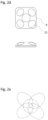
- an example of an MRR structure (9) consisting of multiple-quantum-well based modulating CCR units, will be described.
- the retro-reflecting type in the invention shall not be limited to corner cubes although it here serves as an example.
- the concepts 'CCR unit' and 'CCR array' are used as terms instead of the more generally 'MRR unit' and 'MRR structure' (the latter terminology are used in the claims).
- the FOV is different among different modulating retro-reflector types.
- the FOV of an FSO communicating MRR unit is defined as the direction boundaries, from the MRR unit point of view, within which data communication via light is possible, i.e. within which the MRR unit 'sees' the light source. These boundaries are defined by the features of the specific type of retro-reflecting MRR unit.
- Said CCR units are non-complex, robust, light and economically produced, however suffering from a FOV of about ⁇ 15 degrees.
- This FOV feature may falsely be considered disadvantageous in the current application.
- the tool, with said CCR array firmly integrated on it, can thus be turned in many directions while maintaining communication via at least one of said FSO communication sub links. More specifically, depending on how the array is physically arranged, the complete FOV may also have any shape, adapted to the application so that data communication is enabled when the tool (7) is oriented in its most common ways.
- each circular single CCR unit (21) has a FOV (23) of around ⁇ 15 degrees from the normal of its own plane, which implies a small FOV.
- the upper part of the CCR array (9) has the form of a rather flat tetrahedron and it consists of three CCR units (21a-c).
- the height of the tetrahedron is chosen so that the CCR units (21a-c) are integrated on the three tetrahedron planes turning upwards, but inclined to each other in such a way that their FOV:s are overlapping, yielding a FOV from the complete CCR array to be larger than ⁇ 15 degrees, as can be seen in fig. 2c , disposed in a pattern created by the special form of the CCR array (9) structure.
- the virtual volume covered by the total FOV, at the point of view from the light sensor (32) is cohesive, i.e. it does not contain any holes, weak spots or similar. As is shown in fig.
- the FOV of a single “cone” forms an "ellipse” at a (virtual) plane parallel to the base plane (24) of said CCR array at a certain distance from said CCR array, since each CCR unit is inclined to the base plane.
- a large total FOV meets well the demands indicated in topic no. 2 above.
- each CCR unit (21a, b, c) has its own unique identity and is connected to said processing means of said tool (7).
- the identity consists of an identification key, associated to each CCR unit, and said identification key is included in said FSO communication sub link between corresponding CCR unit and said base station (10).
- the FSO communicating sections of the structure of ellipses is used by the data processing means (3a) in the base station (10) to furthermore determine the orientation of the CCR array.
- the light source is located in the middle of the pattern of said total FOV shown in fig 2c , it is determined that the CCR array is oriented with its base plane more or less perpendicular to the light of said light source (4).
- An example of a more complex array of CCR units is shown in fig. 2d . Consequently, it yields a more complex FOV pattern, as is shown in fig. 2e , but implies also a larger total FOV and a more accurate determination of the CCR array orientation.
- the base station (10) also uses another method to determine the orientation of the CCR array (and thus the tool) which is the art of triangulation.
- said orientation of sail tool is calculated.
- said spatial relations between communicating CCR units are stored as vector parameters in said data memory means (3b) of said base station (10).
- a CCR array may consist of more than one CCR unit where each unit is located a certain distance from each other and not included in the same "package", as is indicated by the embodiments of fig. 2a-e .
- Such concept is applicable when the size and shape of the tool supports it, but it implies a better accuracy when determining the tool orientation through triangulation.
- an object of the invention is met: i.e. to achieve reliable traceability of said tool operation.
- the location of the operation end (8) is known by previously stored vector parameters in said data memory (27) in said tool, and in said data memory (3b) of said base station (10), said vector parameters refer to vectors between each CCR unit and said operation end (6a).
- said orientation of said tool (7) needs to be determined as accurate as possible.
- topic no. 3 loses its importance as the tool orientation loses part of its importance. Being able to determine the location of that CCR unit (close to the operation end) a good opinion is achieved also regarding the location of said operation end.
- Such an example also reduces the need for using other CCR units in the CCR array, at least when it comes to topic no. 3; however, for topic no. 2, i.e. achieving a large FOV in general, it may still be important to have more than one CCR unit (or using a MRR unit with large FOV).
- CCR arrays Many different three-dimensional structures with integrated CCR arrays would be able to provide different shapes and sizes of the FOV, all of which are embodiments of the disclosed invention. Depending on the wanted features for a certain application, the appropriate CCR array structure is chosen.
- the simplest CCR array is one which only contain one CCR unit (appropriately positioned as close to the operation end as possible).
- a small FOV is here compensated by low weight and low complexity, and it can be produced at a lower cost than more advanced structures.
- operational result data including magnitudes from at least one tool sensor and/or diagram data is created and stored in the storage means (27) of said tool (7).
- Said operational result data is sent from the tool (7) to the base station (10) via the existing FSO communication link.
- the coordinates of the tool's operation end (8), now known to the base station (10) are stored together with said operational result data as linked posts in said data memory (3b).
- Said base station (10) now uses the 'allowed association distance' value for determining whether at least one operation point can be connected (i.e. associated) to said posts. If there are none, said allowed association distance may be too small; if there are more than one, it may be too big.
- a goal for the invention is to enable the connection/association of one ambiguous operation point (6a) to each operation.
- Complete operational result data including location data and operation point identity is then transmitted to the upper level production system (1) via the plant network (2). This is how the described method provides traceability of the performed tool operations, at least for the operations performed during the time when an FSO communication link is maintained.
- said base station may also continuously send determined location of said tool's operation end (8) to said tool (7) when said FSO communication link exists for the tool to be updated frequently on its whereabouts. Then, at the failure of said FSO communication link, the probability increases for the tool to store its operational result data together with the location of its operation end in said tool's own data memory (27) as linked posts, thereby maintaining traceability. In this scenario, the tool must not move much after the failing FSO communication link to be effective.
- the system may also be used to achieve control of a tool operation that said tool (7) performs at an operation point (6a) on a workpiece (5).
- said tool is normally disabled from performing any operation at all when said tool is located more than an 'allowed association distance' from said operation point (6a) covered by the light source (4).
- said tool is enabled for performing an operation only when said tool operation end (8) is located less than said allowed association distance from said operation point (6a). For unambiguous reasons, in this embodiment it is important that only one operation point (6a) is 'associated' to said operation end (8) of said tool (7) before enabling said tool (7) for operation.
- Said tool enabling data consisting of either all necessary production data adapted for said operation point (6a), or, when the tool already has the correct parameter settings in general, said data merely consisting of a tool enabling signal. Note; if more than one operation point (e.g. 6a-c) all have same requirements regarding production data, and more detailed traceability is not necessary, the allowed association distance may be set to a larger value.
- the operational result data is sent from the tool (7) to said base station (10) directly after said operation, via said full duplex FSO communication link.
- the complete operational result data is further transferred to said upper level production system (1). Control of the tool operation has been achieved.
- An upper level production system sending production data to a tool short before a tool operation, and receiving tool result data short after the operation, with full traceability, implies a flexible and an efficient production process where decisions by the upper level production system on what tool operations to be performed can be done at the right time, according to the just-in-time production philosophy which constitutes the conditions for low set times in modern LEAN manufacturing. If the data communication is done wirelessly with the benefits of FSO communication compared to RF communication technology, the advantages of the disclosed invention are undoubtful.
Landscapes
- Physics & Mathematics (AREA)
- Engineering & Computer Science (AREA)
- Electromagnetism (AREA)
- Computer Networks & Wireless Communication (AREA)
- General Physics & Mathematics (AREA)
- Remote Sensing (AREA)
- Radar, Positioning & Navigation (AREA)
- Signal Processing (AREA)
- Computing Systems (AREA)
- General Engineering & Computer Science (AREA)
- Manufacturing & Machinery (AREA)
- Quality & Reliability (AREA)
- Automation & Control Theory (AREA)
- Arrangements For Transmission Of Measured Signals (AREA)
- Mobile Radio Communication Systems (AREA)
Claims (13)
- Werkzeug (7), das konfiguriert ist, um einen Vorgang an einem Arbeitspunkt (6a) durchzuführen, wobei das Werkzeug aufweist:- mindestens einen Sensor zum Erzeugen von Ergebnisdaten des operativen Werkzeugs beim Durchführen eines Werkzeugvorgangs,- einen Datenspeicher (27), in dem die Betriebsdaten gespeichert sind,- eine modulierende Retro-Reflektor-Struktur, die im Folgenden MRR-Struktur (9) genannt wird, die konfiguriert ist, um im insatz Daten in einer asymmetrischen optischen Freiraum Kommunikationsverbindung (12) zu senden und zu empfangen,- Verarbeitungsmittel (28), die konfiguriert sind, um die Daten zu verarbeiten und die Daten über die optische Freiraum-Kommunikationsverbindung (12) zu senden, indem sie Signale in der MRR-Struktur (9) modulieren,- wobei die MRR-Struktur (9) aus mindestens einer modulierenden Retroreflektoreinheit besteht, die im Folgenden MRR-Einheit (21) genannt wird.
- Basisstation (10), die konfiguriert ist, um als das abfragende Teil eine optische Freiraum-Kommunikationsverbindung (12) mit einer MRR-Struktur (9) als das andere Teil auf einem Werkzeug (7) nach Anspruch 1 einzurichten, wobei die Basisstation (10) aufweist:- eine gerichtete Lichtquelle (4) zum Übertragen von Licht und einen Lichtsensor (32), wobei der Lichtsensor (32) positioniert ist, um retroreflektiertes Licht von der MRR-Struktur (9) zu erkennen, wenn das gerichtete Licht (4) auf die MRR-Struktur (9) gerichtet ist,- Datenverarbeitungsmittel (3a) zum Verarbeiten von Betriebsergebnisdaten des Werkzeugs, die über die optische Freiraum-Kommunikationsverbindung (12) empfangen werden, und zum Verarbeiten von Betriebsergebnisdaten des Werkzeugs, die über die optische Freiraum-Kommunikationsverbindung (12) zu senden sind,- einen Datenspeicher (3b), in dem Betriebsergebnisdaten von dem Werkzeug (7) durch die Datenverarbeitungsmittel (3a) gespeichert werden, nachdem sie die Betriebsergebnisdaten über die optische Freiraum-Kommunikationsverbindung (12) empfangen haben.
- Verfahren zur Datenkommunikation in einer asymmetrischen optischen Freiraum-Kommunikationsverbindung (12) zwischen einer Basisstation (10) nach Anspruch 2 und einem Werkzeug (7) nach Anspruch 1 an einer Arbeitsstelle, wobei das Werkzeug mindestens einen Vorgang an mindestens einem Arbeitspunkt (6a, 6b, 6c) an einem Werkstück (5) an der Arbeitsstelle durchführt, wobei die Basisstation (10) das abfragenden Teil der optischen Freiraumverbindung (12) bildet, wobei das Werkzeug das andere Teil der optischen Freiraumverbindung bildet, wobei das Verfahren aufweist:- die Tatsache, dass Werkzeugbetriebsdaten zwischen dem Werkzeug (7) und der Basisstation (10) über die eingerichtete optische Freiraum-Kommunikationsverbindung (12) übertragen werden.
- Verfahren nach Anspruch 3, ferner umfassend:- die Tatsache, dass die Basisstation (10) Lenkmittel (33) aufweist, um Licht von der Lichtquelle in verschiedene Richtungen unter verschiedenen Winkeln von einer Ausgangsrichtung zu lenken, und die Lenkmittel (33) durch die Datenverarbeitungsmittel (30) in der Basisstation (10) gesteuert werden,- wobei die Lenkmittel (33) Licht von der Lichtquelle (4) entsprechend einem vorgegebenen Abtastmuster (13) zum Abtasten eines Volumens vor dem Einrichten der optischen Freiraum-Kommunikationsverbindung (12) lenken,- wenn moduliertes retroreflektiertes Licht von der MRR-Struktur (9) durch den Lichtsensor (32) während des Abtastens erfasst wird, wird die Basisstation alarmiert,- wobei die Basisstation Licht in die MRR-Struktur dadurch einkoppelt, dass die Datenverarbeitungsmittel (3a) Korrektursignale von dem Lichtsensor zu den Lenkmitteln (33) senden, um die MRR-Struktur (9) zu verfolgen, wenn der Lichtsensor (32) eine Abweichung des retroreflektierten Lichts von der MRR-Struktur (9) erkennt,- wobei die Basisstation (10) und die MRR-Struktur (9) die optische Freiraumverbindung (12) einrichten, wenn das Licht durch die Basisstation (10) in die MRR-Struktur (9) eingekoppelt worden ist.
- Verfahren nach Anspruch 3 oder 4, ferner umfassend:- die Tatsache, dass die Basisstation elektrische Entfernungsmessmittel (31) zum Messen des Standorts der MRR-Struktur (9) aufweist, wenn von der MRR-Struktur (9) reflektiertes Licht von dem Lichtsensor (32) in der Basisstation (10) erfasst wird,- wobei die elektrischen Entfernungsmessmittel (31) den Standort in Form einer Entfernung von der Lichtquelle (4) zu der MRR-Struktur (9) messen,- wobei die Daten von der Messung in dem Datenspeicher (3b) in der Basisstation (10) gespeichert werden.
- Verfahren nach einem der Ansprüche 3 bis 5, ferner umfassend die Tatsache, dass:- das Werkzeug (7) auch einen Werkzeugdatenspeicher (27) aufweist, in dem die Mittel zum Verarbeiten der Werkzeugdaten (28) Betriebsdaten speichern,- das Werkzeug (7) ferner mindestens einen Sensor aufweist, der Betriebsergebnisdaten beim Durchführen eines Werkzeugvorgangs erzeugt,- die Mittel zum Verarbeiten der Werkzeugdaten (28) die Betriebsergebnisdaten in dem Werkzeugdatenspeicher (27) speichern,- die Mittel zum Verarbeiten der Werkzeugdaten (28) die Betriebsergebnisdaten über die optische Freiraumverbindung (12) an die Basisstation (10) senden,- wobei die Datenverarbeitungsmittel (3a) in der Basisstation die empfangenen Betriebsergebnisdaten und die Standortdaten der MRR-Struktur (9) als verknüpfte Posten in dem Datenspeicher (3b) in der Basisstation (10) speichern.
- Verfahren nach einem der Ansprüche 3 bis 6, ferner umfassend die Tatsache, dass:- die MRR-Struktur (9) auf dem Werkzeug (7) aus mindestens einer MRR-Einheit (21) mit einem eingeschränkten Sichtfeld (23) besteht und die eingerichtete optische Freiraum-Kommunikationsverbindung (12) aus mindestens einer optischen Freiraum-Kommunikations-Sub-Verbindung besteht, die zwischen der mindestens einen kommunizierenden MRR-Einheit (21) und der Basisstation eingerichtet ist,- ein eindeutiger Identifikationsschlüssel der mindestens einen MRR-Einheit (21) in der entsprechenden optischen Freiraum-Kommunikations-Sub-Verbindung enthalten ist, wenn die mindestens eine MRR-Einheit (21) mit der Basisstation (10) kommuniziert,- das Messen des Standorts der MRR-Struktur (9) darin besteht, den Standort der mindestens einen MRR-Einheit (21) zu messen,- in dem Datenspeicher (3b) in der Basisstation (10) und vor einem Werkzeugvorgang an dem mindestens einen Arbeitspunkt (6a, 6b, 6c) an mindestens einem Werkstück (5) die folgenden Daten gespeichert worden sind:o Standortdaten von mindestens einem Arbeitspunkt (6a, 6b, 6c),o Standortdaten des Endes des Vorgangs (8) des Werkzeugs (7) in Bezug auf die MRR-Struktur (9) auf dem Werkzeug (7),o eine maximal zulässige Verbindungsentfernung zwischen dem Standort des Endes des Vorgangs (8) und dem Standort mindestens eines Arbeitspunkts (6a, 6b, 6c).
- Verfahren nach einem der Ansprüche 3 bis 7, ferner umfassend die Tatsache, dass:- die Basisstation (10) die Standortdaten des Endes des Vorgangs (8) des Werkzeugs (7) basierend auf den Standortdaten der mindestens einen identifizierten MRR-Einheit (21) berechnet, die in der Datenkommunikation der eingerichteten optischen Freiraum-Kommunikationsverbindung (12) vorhanden ist,- die Basisstation (10) die Standortdaten des Endes des Vorgangs (8) mit den Standortdaten des mindestens einen Arbeitspunkts (6a, 6b, 6c) am aktuellen Werkstück (5) vergleicht,- die Basisstation (10) bestimmt, ob mindestens ein Arbeitspunkt (6a, 6b, 6c) mit dem Werkzeugvorgang basierend auf der maximal zulässigen Verbindungsentfernung verbunden werden muss,- die Basisstation (10) dieses Bestimmen durch Verknüpfen der bereits verknüpften Posten mit einem beliebigen Arbeitspunkt (6a, 6b, 6c) aufzeichnet, von dem bestimmt wird, dass er in die zulässige Verbindungsentfernung fällt, und durch nicht Verknüpfen der bereits verknüpften Posten mit einem beliebigen Arbeitspunkt, der als außerhalb der zulässigen Verbindungsentfernung liegend bestimmt wird.
- Werkzeug (7) nach Anspruch 1, ferner umfassend die Tatsache, dass:- die mindestens eine MRR-Einheit (21) eine eindeutige Identität hat und in Bezug (11) auf das Ende des Vorgangs (8) des Werkzeugs (7) wohldefiniert positioniert ist,- die mindestens eine MRR-Einheit (21) mit den Mitteln zum Verarbeiten (28) verbunden ist,- die mindestens eine MRR-Einheit (21) konfiguriert ist, um in einer optischen Freiraum-Kommunikationsverbindung (12) zu kommunizieren,- die MRR-Struktur (9) auf dem Werkzeug (7) derart angeordnet ist, dass das gesamte Sichtfeld der MRR-Struktur (9) für ein Gegenstück für optische Freiraum-Kommunikation kohärent ist.
- Werkzeug (7) nach Anspruch 1 oder 9, ferner umfassend die Tatsache, dass:- die mindestens eine MRR-Einheit (21) aus Elektroabsorptionsmodulatoren mit "Mehrfach-Quantentöpfen" besteht,- die mindestens eine MRR-Einheit (21) GaAs- oder InP-basierte Halbleiter enthält.
- Basisstation (10) nach Anspruch 2, ferner umfassend:- Lenkmittel (33) zum Lenken von Licht von der gerichteten Lichtquelle (4) in verschiedene Richtungen, wobei die Lenkmittel (33) von den Datenverarbeitungsmitteln (3a) in der Basisstation (10) gesteuert werden,- der Lichtsensor (32) zum Erkennen einer Abweichung des retroreflektierten Lichts von der MRR-Struktur (9) konfiguriert ist,- wobei die Datenverarbeitungsmittel (3a) mit dem Lichtsensor (32) und den Lenkmitteln (33) verbunden sind und die Datenverarbeitungsmittel (3a) zum Senden von Korrektursignalen von dem Lichtsensor (32) an die Lenkmittel (33) konfiguriert sind, um die Abweichung zu minimieren.
- Basisstation (10) nach Anspruch 2 oder 11, ferner umfassend:- elektronische Entfernungsmessmittel (31) zum Messen der Entfernung von der Lichtquelle (4) zu der MRR-Struktur (9) durch Analysieren von retroreflektiertem Licht von der MRR-Struktur (9),- die Tatsache, dass die Datenverarbeitungsmittel (3a) konfiguriert sind, um Daten von den elektrischen Entfernungsmessungen in dem Datenspeicher (3b) in der Basisstation (10) zu speichern.
- System, umfassend:- mindestens ein Werkzeug (7) nach Anspruch 1, 9 oder 10,- mindestens eine Basisstation (10) nach Anspruch 2, 11 oder 12,- ein übergeordnetes Produktionssystem (1), das über ein Netzwerk (2) mit der mindestens einen Basisstation (10) verbunden ist,- wobei das übergeordnete Produktionssystem (1) konfiguriert ist, um den mindestens einen Werkzeugvorgang durch Senden von Anweisungen an die entsprechende Basisstation (10) zu steuern,- wobei das übergeordnete Produktionssystem (1) auch konfiguriert ist, um Betriebsergebnisdaten von dem mindestens einen Werkzeug (7) über die entsprechende Basisstation (10) zu empfangen.
Applications Claiming Priority (2)
| Application Number | Priority Date | Filing Date | Title |
|---|---|---|---|
| SE1830249A SE542636C2 (en) | 2018-08-30 | 2018-08-30 | A method for achieving traceability of a tool operation |
| PCT/SE2019/050804 WO2020046195A1 (en) | 2018-08-30 | 2019-08-28 | A method for achieving traceability of a tool operation |
Publications (2)
| Publication Number | Publication Date |
|---|---|
| EP3844581A1 EP3844581A1 (de) | 2021-07-07 |
| EP3844581B1 true EP3844581B1 (de) | 2023-04-05 |
Family
ID=68290308
Family Applications (1)
| Application Number | Title | Priority Date | Filing Date |
|---|---|---|---|
| EP19790318.0A Active EP3844581B1 (de) | 2018-08-30 | 2019-08-28 | Verfahren zum erreichen der verfolgbarkeit eines werkzeugbetriebs |
Country Status (3)
| Country | Link |
|---|---|
| EP (1) | EP3844581B1 (de) |
| SE (1) | SE542636C2 (de) |
| WO (1) | WO2020046195A1 (de) |
Families Citing this family (1)
| Publication number | Priority date | Publication date | Assignee | Title |
|---|---|---|---|---|
| WO2022078862A1 (en) * | 2020-10-12 | 2022-04-21 | Signify Holding B.V. | A system for assisting a user in a multi-phase process and a method thereof |
Family Cites Families (7)
| Publication number | Priority date | Publication date | Assignee | Title |
|---|---|---|---|---|
| SE520096C2 (sv) | 1998-12-10 | 2003-05-27 | Atlas Copco Tools Ab | System för kraftverktyg innefattande till- och frånkopplingsbar minnesmodul för lagring och överföring av data mellan olika enheter |
| WO2006059927A1 (en) | 2004-11-30 | 2006-06-08 | Atlas Copco Tools Ab | System for identifying different working positions of a portable power tool and for monitoring and governing the operation of a power tool |
| DE102006024904B4 (de) | 2006-05-24 | 2012-10-25 | Franz Klaiber | Verfahren zum Bereitstellen von Werkzeugen für das Herstellen und/oder Bearbeiten von Gegenständen, wobei den Werkzeugen und Ablageorten Identifikationen zugeordnet werden |
| US8301032B2 (en) * | 2008-02-12 | 2012-10-30 | Arun Kumar Majumdar | Wide field-of-view amplified fiber-retro for secure high data rate communications and remote data transfer |
| EP3007862B1 (de) | 2013-06-13 | 2022-01-26 | Stanley Black & Decker, Inc. | Drahtloses werkzeugsystem |
| WO2015024686A1 (en) | 2013-08-22 | 2015-02-26 | Atlas Copco Industrial Technique Ab | A localization system for a movable power tool. |
| EP2916189B1 (de) * | 2014-03-06 | 2019-05-08 | Hexagon Technology Center GmbH | Qualitätsgesicherte Herstellung |
-
2018
- 2018-08-30 SE SE1830249A patent/SE542636C2/en not_active IP Right Cessation
-
2019
- 2019-08-28 WO PCT/SE2019/050804 patent/WO2020046195A1/en not_active Ceased
- 2019-08-28 EP EP19790318.0A patent/EP3844581B1/de active Active
Also Published As
| Publication number | Publication date |
|---|---|
| WO2020046195A1 (en) | 2020-03-05 |
| EP3844581A1 (de) | 2021-07-07 |
| SE1830249A1 (en) | 2020-03-01 |
| SE542636C2 (en) | 2020-06-23 |
Similar Documents
| Publication | Publication Date | Title |
|---|---|---|
| US10546167B2 (en) | System and method of operating a manufacturing cell | |
| EP1437636B1 (de) | Mobiler Roboter, sowie System und Verfahren zur autonomen Navigation eines solchen Roboters | |
| EP1435061B1 (de) | Mobile objektverfolgung | |
| US11892551B2 (en) | Safety system | |
| US11558729B2 (en) | Safety system and method | |
| CN104275698A (zh) | 生产装置 | |
| US12072450B2 (en) | Method for optically scanning and measuring an environment using a 3D measurement device and near field communication | |
| EP3671273B1 (de) | System zur groblokalisierung beweglicher kooperativer ziele bei der lasertracker-basierten industriellen objektvermessung | |
| CN106843280B (zh) | 一种机器人智能跟随系统 | |
| KR101921113B1 (ko) | 탐지용 하이브리드 가시광 rfid 태그 및 이에 사용되는 로봇시스템 | |
| KR102827789B1 (ko) | 공구의 포지션 및/또는 로케이션 및/또는 움직임을 모니터링하기 위한 디바이스 | |
| KR20230101268A (ko) | 로봇 암 제어 장치 및 방법 | |
| EP3844581B1 (de) | Verfahren zum erreichen der verfolgbarkeit eines werkzeugbetriebs | |
| JP2020136876A (ja) | 基地局選択装置と基地局選択方法 | |
| Jin et al. | A Passive Eye-in-Hand" Camera" for Miniature Robots | |
| KR102123111B1 (ko) | Rfid 리더 장치 및 서버 장치 | |
| EP3938801A1 (de) | Verfahren zur ortung eines retroreflektierenden objekts auf einem werkzeug | |
| US20250378289A1 (en) | Systems and methods for alignment of a robotic interface | |
| US20240256412A1 (en) | Role management of device nodes in an aggregated node system | |
| Wang et al. | Design of an accurate yet low-cost distributed module for vehicular relative positioning: Hardware prototype design and algorithms | |
| Kokert et al. | Indoor localization system based on galvanometer-laser-scanning for numerous mobile tags (GaLocate) | |
| KR20200095425A (ko) | Rfid 리더 장치 및 서버 장치 | |
| KR102466217B1 (ko) | 실내공간 측위기술을 활용한 공작물의 조립지원시스템 | |
| Motroni et al. | UAV-Based RFID localization of Pedestrian Workers and Machinery for Safety Applications |
Legal Events
| Date | Code | Title | Description |
|---|---|---|---|
| STAA | Information on the status of an ep patent application or granted ep patent |
Free format text: STATUS: UNKNOWN |
|
| STAA | Information on the status of an ep patent application or granted ep patent |
Free format text: STATUS: THE INTERNATIONAL PUBLICATION HAS BEEN MADE |
|
| STAA | Information on the status of an ep patent application or granted ep patent |
Free format text: STATUS: REQUEST FOR EXAMINATION WAS MADE |
|
| PUAI | Public reference made under article 153(3) epc to a published international application that has entered the european phase |
Free format text: ORIGINAL CODE: 0009012 |
|
| 17P | Request for examination filed |
Effective date: 20210330 |
|
| AK | Designated contracting states |
Kind code of ref document: A1 Designated state(s): AL AT BE BG CH CY CZ DE DK EE ES FI FR GB GR HR HU IE IS IT LI LT LU LV MC MK MT NL NO PL PT RO RS SE SI SK SM TR |
|
| DAV | Request for validation of the european patent (deleted) | ||
| DAX | Request for extension of the european patent (deleted) | ||
| STAA | Information on the status of an ep patent application or granted ep patent |
Free format text: STATUS: EXAMINATION IS IN PROGRESS |
|
| 17Q | First examination report despatched |
Effective date: 20220203 |
|
| GRAP | Despatch of communication of intention to grant a patent |
Free format text: ORIGINAL CODE: EPIDOSNIGR1 |
|
| STAA | Information on the status of an ep patent application or granted ep patent |
Free format text: STATUS: GRANT OF PATENT IS INTENDED |
|
| RIC1 | Information provided on ipc code assigned before grant |
Ipc: H04B 10/114 20130101ALI20220715BHEP Ipc: H04B 10/112 20130101ALI20220715BHEP Ipc: G05B 19/418 20060101AFI20220715BHEP |
|
| INTG | Intention to grant announced |
Effective date: 20220809 |
|
| GRAS | Grant fee paid |
Free format text: ORIGINAL CODE: EPIDOSNIGR3 |
|
| GRAA | (expected) grant |
Free format text: ORIGINAL CODE: 0009210 |
|
| STAA | Information on the status of an ep patent application or granted ep patent |
Free format text: STATUS: THE PATENT HAS BEEN GRANTED |
|
| AK | Designated contracting states |
Kind code of ref document: B1 Designated state(s): AL AT BE BG CH CY CZ DE DK EE ES FI FR GB GR HR HU IE IS IT LI LT LU LV MC MK MT NL NO PL PT RO RS SE SI SK SM TR |
|
| REG | Reference to a national code |
Ref country code: GB Ref legal event code: FG4D |
|
| REG | Reference to a national code |
Ref country code: CH Ref legal event code: EP |
|
| REG | Reference to a national code |
Ref country code: AT Ref legal event code: REF Ref document number: 1558696 Country of ref document: AT Kind code of ref document: T Effective date: 20230415 |
|
| REG | Reference to a national code |
Ref country code: DE Ref legal event code: R096 Ref document number: 602019027277 Country of ref document: DE |
|
| REG | Reference to a national code |
Ref country code: IE Ref legal event code: FG4D |
|
| REG | Reference to a national code |
Ref country code: SE Ref legal event code: TRGR Ref country code: LT Ref legal event code: MG9D |
|
| REG | Reference to a national code |
Ref country code: NL Ref legal event code: MP Effective date: 20230405 |
|
| REG | Reference to a national code |
Ref country code: AT Ref legal event code: MK05 Ref document number: 1558696 Country of ref document: AT Kind code of ref document: T Effective date: 20230405 |
|
| PG25 | Lapsed in a contracting state [announced via postgrant information from national office to epo] |
Ref country code: NL Free format text: LAPSE BECAUSE OF FAILURE TO SUBMIT A TRANSLATION OF THE DESCRIPTION OR TO PAY THE FEE WITHIN THE PRESCRIBED TIME-LIMIT Effective date: 20230405 |
|
| PG25 | Lapsed in a contracting state [announced via postgrant information from national office to epo] |
Ref country code: PT Free format text: LAPSE BECAUSE OF FAILURE TO SUBMIT A TRANSLATION OF THE DESCRIPTION OR TO PAY THE FEE WITHIN THE PRESCRIBED TIME-LIMIT Effective date: 20230807 Ref country code: NO Free format text: LAPSE BECAUSE OF FAILURE TO SUBMIT A TRANSLATION OF THE DESCRIPTION OR TO PAY THE FEE WITHIN THE PRESCRIBED TIME-LIMIT Effective date: 20230705 Ref country code: ES Free format text: LAPSE BECAUSE OF FAILURE TO SUBMIT A TRANSLATION OF THE DESCRIPTION OR TO PAY THE FEE WITHIN THE PRESCRIBED TIME-LIMIT Effective date: 20230405 Ref country code: AT Free format text: LAPSE BECAUSE OF FAILURE TO SUBMIT A TRANSLATION OF THE DESCRIPTION OR TO PAY THE FEE WITHIN THE PRESCRIBED TIME-LIMIT Effective date: 20230405 |
|
| PG25 | Lapsed in a contracting state [announced via postgrant information from national office to epo] |
Ref country code: RS Free format text: LAPSE BECAUSE OF FAILURE TO SUBMIT A TRANSLATION OF THE DESCRIPTION OR TO PAY THE FEE WITHIN THE PRESCRIBED TIME-LIMIT Effective date: 20230405 Ref country code: PL Free format text: LAPSE BECAUSE OF FAILURE TO SUBMIT A TRANSLATION OF THE DESCRIPTION OR TO PAY THE FEE WITHIN THE PRESCRIBED TIME-LIMIT Effective date: 20230405 Ref country code: LV Free format text: LAPSE BECAUSE OF FAILURE TO SUBMIT A TRANSLATION OF THE DESCRIPTION OR TO PAY THE FEE WITHIN THE PRESCRIBED TIME-LIMIT Effective date: 20230405 Ref country code: LT Free format text: LAPSE BECAUSE OF FAILURE TO SUBMIT A TRANSLATION OF THE DESCRIPTION OR TO PAY THE FEE WITHIN THE PRESCRIBED TIME-LIMIT Effective date: 20230405 Ref country code: IS Free format text: LAPSE BECAUSE OF FAILURE TO SUBMIT A TRANSLATION OF THE DESCRIPTION OR TO PAY THE FEE WITHIN THE PRESCRIBED TIME-LIMIT Effective date: 20230805 Ref country code: HR Free format text: LAPSE BECAUSE OF FAILURE TO SUBMIT A TRANSLATION OF THE DESCRIPTION OR TO PAY THE FEE WITHIN THE PRESCRIBED TIME-LIMIT Effective date: 20230405 Ref country code: GR Free format text: LAPSE BECAUSE OF FAILURE TO SUBMIT A TRANSLATION OF THE DESCRIPTION OR TO PAY THE FEE WITHIN THE PRESCRIBED TIME-LIMIT Effective date: 20230706 Ref country code: AL Free format text: LAPSE BECAUSE OF FAILURE TO SUBMIT A TRANSLATION OF THE DESCRIPTION OR TO PAY THE FEE WITHIN THE PRESCRIBED TIME-LIMIT Effective date: 20230405 |
|
| PG25 | Lapsed in a contracting state [announced via postgrant information from national office to epo] |
Ref country code: FI Free format text: LAPSE BECAUSE OF FAILURE TO SUBMIT A TRANSLATION OF THE DESCRIPTION OR TO PAY THE FEE WITHIN THE PRESCRIBED TIME-LIMIT Effective date: 20230405 |
|
| REG | Reference to a national code |
Ref country code: DE Ref legal event code: R097 Ref document number: 602019027277 Country of ref document: DE |
|
| PG25 | Lapsed in a contracting state [announced via postgrant information from national office to epo] |
Ref country code: SK Free format text: LAPSE BECAUSE OF FAILURE TO SUBMIT A TRANSLATION OF THE DESCRIPTION OR TO PAY THE FEE WITHIN THE PRESCRIBED TIME-LIMIT Effective date: 20230405 |
|
| PG25 | Lapsed in a contracting state [announced via postgrant information from national office to epo] |
Ref country code: SM Free format text: LAPSE BECAUSE OF FAILURE TO SUBMIT A TRANSLATION OF THE DESCRIPTION OR TO PAY THE FEE WITHIN THE PRESCRIBED TIME-LIMIT Effective date: 20230405 Ref country code: SK Free format text: LAPSE BECAUSE OF FAILURE TO SUBMIT A TRANSLATION OF THE DESCRIPTION OR TO PAY THE FEE WITHIN THE PRESCRIBED TIME-LIMIT Effective date: 20230405 Ref country code: RO Free format text: LAPSE BECAUSE OF FAILURE TO SUBMIT A TRANSLATION OF THE DESCRIPTION OR TO PAY THE FEE WITHIN THE PRESCRIBED TIME-LIMIT Effective date: 20230405 Ref country code: EE Free format text: LAPSE BECAUSE OF FAILURE TO SUBMIT A TRANSLATION OF THE DESCRIPTION OR TO PAY THE FEE WITHIN THE PRESCRIBED TIME-LIMIT Effective date: 20230405 Ref country code: DK Free format text: LAPSE BECAUSE OF FAILURE TO SUBMIT A TRANSLATION OF THE DESCRIPTION OR TO PAY THE FEE WITHIN THE PRESCRIBED TIME-LIMIT Effective date: 20230405 Ref country code: CZ Free format text: LAPSE BECAUSE OF FAILURE TO SUBMIT A TRANSLATION OF THE DESCRIPTION OR TO PAY THE FEE WITHIN THE PRESCRIBED TIME-LIMIT Effective date: 20230405 |
|
| PLBE | No opposition filed within time limit |
Free format text: ORIGINAL CODE: 0009261 |
|
| STAA | Information on the status of an ep patent application or granted ep patent |
Free format text: STATUS: NO OPPOSITION FILED WITHIN TIME LIMIT |
|
| PG25 | Lapsed in a contracting state [announced via postgrant information from national office to epo] |
Ref country code: MC Free format text: LAPSE BECAUSE OF FAILURE TO SUBMIT A TRANSLATION OF THE DESCRIPTION OR TO PAY THE FEE WITHIN THE PRESCRIBED TIME-LIMIT Effective date: 20230405 |
|
| 26N | No opposition filed |
Effective date: 20240108 |
|
| REG | Reference to a national code |
Ref country code: CH Ref legal event code: PL |
|
| PG25 | Lapsed in a contracting state [announced via postgrant information from national office to epo] |
Ref country code: MC Free format text: LAPSE BECAUSE OF FAILURE TO SUBMIT A TRANSLATION OF THE DESCRIPTION OR TO PAY THE FEE WITHIN THE PRESCRIBED TIME-LIMIT Effective date: 20230405 |
|
| PG25 | Lapsed in a contracting state [announced via postgrant information from national office to epo] |
Ref country code: LU Free format text: LAPSE BECAUSE OF NON-PAYMENT OF DUE FEES Effective date: 20230828 |
|
| PG25 | Lapsed in a contracting state [announced via postgrant information from national office to epo] |
Ref country code: LU Free format text: LAPSE BECAUSE OF NON-PAYMENT OF DUE FEES Effective date: 20230828 Ref country code: CH Free format text: LAPSE BECAUSE OF NON-PAYMENT OF DUE FEES Effective date: 20230831 |
|
| PG25 | Lapsed in a contracting state [announced via postgrant information from national office to epo] |
Ref country code: SI Free format text: LAPSE BECAUSE OF FAILURE TO SUBMIT A TRANSLATION OF THE DESCRIPTION OR TO PAY THE FEE WITHIN THE PRESCRIBED TIME-LIMIT Effective date: 20230405 |
|
| REG | Reference to a national code |
Ref country code: BE Ref legal event code: MM Effective date: 20230831 |
|
| REG | Reference to a national code |
Ref country code: IE Ref legal event code: MM4A |
|
| PG25 | Lapsed in a contracting state [announced via postgrant information from national office to epo] |
Ref country code: SI Free format text: LAPSE BECAUSE OF FAILURE TO SUBMIT A TRANSLATION OF THE DESCRIPTION OR TO PAY THE FEE WITHIN THE PRESCRIBED TIME-LIMIT Effective date: 20230405 Ref country code: IT Free format text: LAPSE BECAUSE OF FAILURE TO SUBMIT A TRANSLATION OF THE DESCRIPTION OR TO PAY THE FEE WITHIN THE PRESCRIBED TIME-LIMIT Effective date: 20230405 |
|
| PG25 | Lapsed in a contracting state [announced via postgrant information from national office to epo] |
Ref country code: IE Free format text: LAPSE BECAUSE OF NON-PAYMENT OF DUE FEES Effective date: 20230828 |
|
| PG25 | Lapsed in a contracting state [announced via postgrant information from national office to epo] |
Ref country code: IE Free format text: LAPSE BECAUSE OF NON-PAYMENT OF DUE FEES Effective date: 20230828 |
|
| PG25 | Lapsed in a contracting state [announced via postgrant information from national office to epo] |
Ref country code: BE Free format text: LAPSE BECAUSE OF NON-PAYMENT OF DUE FEES Effective date: 20230831 |
|
| PG25 | Lapsed in a contracting state [announced via postgrant information from national office to epo] |
Ref country code: BG Free format text: LAPSE BECAUSE OF FAILURE TO SUBMIT A TRANSLATION OF THE DESCRIPTION OR TO PAY THE FEE WITHIN THE PRESCRIBED TIME-LIMIT Effective date: 20230405 |
|
| PG25 | Lapsed in a contracting state [announced via postgrant information from national office to epo] |
Ref country code: BG Free format text: LAPSE BECAUSE OF FAILURE TO SUBMIT A TRANSLATION OF THE DESCRIPTION OR TO PAY THE FEE WITHIN THE PRESCRIBED TIME-LIMIT Effective date: 20230405 |
|
| PG25 | Lapsed in a contracting state [announced via postgrant information from national office to epo] |
Ref country code: CY Free format text: LAPSE BECAUSE OF FAILURE TO SUBMIT A TRANSLATION OF THE DESCRIPTION OR TO PAY THE FEE WITHIN THE PRESCRIBED TIME-LIMIT; INVALID AB INITIO Effective date: 20190828 |
|
| PG25 | Lapsed in a contracting state [announced via postgrant information from national office to epo] |
Ref country code: HU Free format text: LAPSE BECAUSE OF FAILURE TO SUBMIT A TRANSLATION OF THE DESCRIPTION OR TO PAY THE FEE WITHIN THE PRESCRIBED TIME-LIMIT; INVALID AB INITIO Effective date: 20190828 |
|
| PGFP | Annual fee paid to national office [announced via postgrant information from national office to epo] |
Ref country code: DE Payment date: 20250829 Year of fee payment: 7 |
|
| PGFP | Annual fee paid to national office [announced via postgrant information from national office to epo] |
Ref country code: GB Payment date: 20250827 Year of fee payment: 7 |
|
| PGFP | Annual fee paid to national office [announced via postgrant information from national office to epo] |
Ref country code: FR Payment date: 20250827 Year of fee payment: 7 |
|
| PGFP | Annual fee paid to national office [announced via postgrant information from national office to epo] |
Ref country code: SE Payment date: 20250827 Year of fee payment: 7 |
|
| PG25 | Lapsed in a contracting state [announced via postgrant information from national office to epo] |
Ref country code: TR Free format text: LAPSE BECAUSE OF FAILURE TO SUBMIT A TRANSLATION OF THE DESCRIPTION OR TO PAY THE FEE WITHIN THE PRESCRIBED TIME-LIMIT Effective date: 20230405 |