EP3845255B1 - Dispositif d'aide au pompage cardiaque - Google Patents
Dispositif d'aide au pompage cardiaque Download PDFInfo
- Publication number
- EP3845255B1 EP3845255B1 EP19855486.7A EP19855486A EP3845255B1 EP 3845255 B1 EP3845255 B1 EP 3845255B1 EP 19855486 A EP19855486 A EP 19855486A EP 3845255 B1 EP3845255 B1 EP 3845255B1
- Authority
- EP
- European Patent Office
- Prior art keywords
- diaphragm
- heart
- cardiac output
- compression
- support apparatus
- Prior art date
- Legal status (The legal status is an assumption and is not a legal conclusion. Google has not performed a legal analysis and makes no representation as to the accuracy of the status listed.)
- Active
Links
Images


Classifications
-
- A—HUMAN NECESSITIES
- A61—MEDICAL OR VETERINARY SCIENCE; HYGIENE
- A61M—DEVICES FOR INTRODUCING MEDIA INTO, OR ONTO, THE BODY; DEVICES FOR TRANSDUCING BODY MEDIA OR FOR TAKING MEDIA FROM THE BODY; DEVICES FOR PRODUCING OR ENDING SLEEP OR STUPOR
- A61M60/00—Blood pumps; Devices for mechanical circulatory actuation; Balloon pumps for circulatory assistance
- A61M60/10—Location thereof with respect to the patient's body
- A61M60/122—Implantable pumps or pumping devices, i.e. the blood being pumped inside the patient's body
- A61M60/165—Implantable pumps or pumping devices, i.e. the blood being pumped inside the patient's body implantable in, on, or around the heart
- A61M60/191—Implantable pumps or pumping devices, i.e. the blood being pumped inside the patient's body implantable in, on, or around the heart mechanically acting upon the outside of the patient's native heart, e.g. compressive structures placed around the heart
-
- A—HUMAN NECESSITIES
- A61—MEDICAL OR VETERINARY SCIENCE; HYGIENE
- A61M—DEVICES FOR INTRODUCING MEDIA INTO, OR ONTO, THE BODY; DEVICES FOR TRANSDUCING BODY MEDIA OR FOR TAKING MEDIA FROM THE BODY; DEVICES FOR PRODUCING OR ENDING SLEEP OR STUPOR
- A61M60/00—Blood pumps; Devices for mechanical circulatory actuation; Balloon pumps for circulatory assistance
- A61M60/20—Type thereof
- A61M60/289—Devices for mechanical circulatory actuation assisting the residual heart function by means mechanically acting upon the patient's native heart or blood vessel structure, e.g. direct cardiac compression [DCC] devices
-
- A—HUMAN NECESSITIES
- A61—MEDICAL OR VETERINARY SCIENCE; HYGIENE
- A61M—DEVICES FOR INTRODUCING MEDIA INTO, OR ONTO, THE BODY; DEVICES FOR TRANSDUCING BODY MEDIA OR FOR TAKING MEDIA FROM THE BODY; DEVICES FOR PRODUCING OR ENDING SLEEP OR STUPOR
- A61M60/00—Blood pumps; Devices for mechanical circulatory actuation; Balloon pumps for circulatory assistance
- A61M60/40—Details relating to driving
- A61M60/465—Details relating to driving for devices for mechanical circulatory actuation
- A61M60/468—Details relating to driving for devices for mechanical circulatory actuation the force acting on the actuation means being hydraulic or pneumatic
-
- A—HUMAN NECESSITIES
- A61—MEDICAL OR VETERINARY SCIENCE; HYGIENE
- A61M—DEVICES FOR INTRODUCING MEDIA INTO, OR ONTO, THE BODY; DEVICES FOR TRANSDUCING BODY MEDIA OR FOR TAKING MEDIA FROM THE BODY; DEVICES FOR PRODUCING OR ENDING SLEEP OR STUPOR
- A61M60/00—Blood pumps; Devices for mechanical circulatory actuation; Balloon pumps for circulatory assistance
- A61M60/50—Details relating to control
- A61M60/508—Electronic control means, e.g. for feedback regulation
- A61M60/515—Regulation using real-time patient data
-
- A—HUMAN NECESSITIES
- A61—MEDICAL OR VETERINARY SCIENCE; HYGIENE
- A61M—DEVICES FOR INTRODUCING MEDIA INTO, OR ONTO, THE BODY; DEVICES FOR TRANSDUCING BODY MEDIA OR FOR TAKING MEDIA FROM THE BODY; DEVICES FOR PRODUCING OR ENDING SLEEP OR STUPOR
- A61M60/00—Blood pumps; Devices for mechanical circulatory actuation; Balloon pumps for circulatory assistance
- A61M60/80—Constructional details other than related to driving
- A61M60/839—Constructional details other than related to driving of devices for mechanical circulatory actuation
-
- A—HUMAN NECESSITIES
- A61—MEDICAL OR VETERINARY SCIENCE; HYGIENE
- A61M—DEVICES FOR INTRODUCING MEDIA INTO, OR ONTO, THE BODY; DEVICES FOR TRANSDUCING BODY MEDIA OR FOR TAKING MEDIA FROM THE BODY; DEVICES FOR PRODUCING OR ENDING SLEEP OR STUPOR
- A61M60/00—Blood pumps; Devices for mechanical circulatory actuation; Balloon pumps for circulatory assistance
- A61M60/80—Constructional details other than related to driving
- A61M60/855—Constructional details other than related to driving of implantable pumps or pumping devices
- A61M60/865—Devices for guiding or inserting pumps or pumping devices into the patient's body
-
- A—HUMAN NECESSITIES
- A61—MEDICAL OR VETERINARY SCIENCE; HYGIENE
- A61M—DEVICES FOR INTRODUCING MEDIA INTO, OR ONTO, THE BODY; DEVICES FOR TRANSDUCING BODY MEDIA OR FOR TAKING MEDIA FROM THE BODY; DEVICES FOR PRODUCING OR ENDING SLEEP OR STUPOR
- A61M2205/00—General characteristics of the apparatus
- A61M2205/04—General characteristics of the apparatus implanted
Definitions
- the present invention relates to a technology for directly compressing a patient's heart whose cardiac output function has significantly deteriorated due to a myocardial infarction.
- the myocardial infarction which is a heart disease is a disease which causes necrosis of cardiac muscles as blood flows to cardiac muscles are obstructed by stenosis or blockage of coronary arteries.
- a patient who suffers from an acute myocardial infarction often has cardiac arrest within approximately one hour after the occurrence of subjective symptoms, so that it is extremely important to make the blood flows to the entire body promptly resumed.
- a conventional method of treating the acute myocardial infarction patient is to deal with the situation sequentially by performing emergency transport at the time of discovery of the subjective symptoms such as chest pain, deciding treatment policies, preparing for a surgery, and making arrangements for cardiovascular surgery medical specialists.
- a Percutaneous Cardiopulmonary Support (PCPS) device to resume the blood flows to the entire body and a treatment to support blood circulation by open chest cardiac massage are employed.
- This Percutaneous Cardiopulmonary Support device can be attached via a surgical operation conducted by a doctor who is not a cardiovascular surgery medical specialist; however, there are risks of inducing complications such as shortage of an auxiliary flow rate, blood clots, and lower extremity ischemia.
- the open chest cardiac massage has a high cardiac output effect, but requires considerable skills regarding power adjustment and cardiac output cycles.
- an apparatus for treating a heart trouble includes: a confined structure to surround a substantial portion of a patient's heart; a first expansion pocket that applies a pressure to a left ventricle of the heart during a part of a pumping cycle of the heart; and a second expansion pocket that applies a pressure to a right ventricle of the heart during a part of the pumping cycle of the heart, wherein the pressures imparted by the first and second expansion pockets can be independently controlled so that the different pressures are selectively applied to the left ventricle and the right ventricle (see PTL 1).
- a heart compression system configured so that first and second expandable balloons are attached at fixed positions on an inner surface of an outer shell which is manufactured and customized to make its shape substantially fit a part of an outline of a heart at the end of a diastole, which is acquired by an imaging system; and the first and second expandable balloons expand to compress a left ventricle free wall and a right ventricle free wall, respectively, in a state where the outer shell is naturally positioned in a pericardium space (see PTL 2).
- an implantable device for improving the heart's pumping function by causing the pumping function to work by using a hydraulic system in order to make piston reciprocating motions operate respectively so that first and second chambers which are adapted to retain a liquid pressure are pressure-controlled with respect to a heart contact member which is adapted to make an external force act on a left ventricle and a right ventricle, respectively, of a patient's heart (see PTL 3).
- PTL 1 has the confined structure, which uses a biocompatible material such as silicone or polyurethane, to surround the substantial portion of the heart; and although it has flexibility, it is necessary to perform a thoracotomy by opening a chest of the target person along the length equal to or longer than the width of their heart in order to locate the apparatus at the heart.
- a biocompatible material such as silicone or polyurethane
- the heart contact member is made of a ceramic material or a carbon material and is embedded in the body together with a fixing member adapted to be fixed to, for example, the patient's breastbone or ribs; and, therefore, in this case as well similarly to the aforementioned PTL 1 and PTL 2, it is necessary to perform the thoracotomy by opening the chest of the target person along the length equal to or longer than the width of their heart.
- each one of the aforementioned PTL 1 to PTL 3 is required to perform the thoracotomy by opening the chest of the target person along the length equal to or longer than the width of their heart when placing the apparatus having the heart pumping support function at the patient's heart, so that the problem of heavy physical burden on the target person remains.
- the present invention was devised in consideration of the above-described circumstances and proposes a cardiac output support apparatus capable of providing life support to the target person by significantly reducing the physical burden on the target person.
- a cardiac output support apparatus as defined by independent claim 1. Any methods for treatment of the human or animal body by surgery or therapy mentioned in the following are not encompassed by the wording of the claims but are considered as useful for understanding the invention.
- the target person's chest is incised along the length approximately equal to a diameter of the tubular joint; and by increasing a gas pressure inside the diaphragm from outside in a state where the tubular joint is inserted into the incised part, the lower heart part can be covered and wrapped with the diaphragm and simultaneously each compression balloon can be positioned. Consequently, if the cardiac output support apparatus is employed, it is no longer necessary to incise the target person's chest along the length equal to or longer than the width of the heart and the physical burden on the target person can be reduced significantly.
- a peripheral region of the diaphragm which does not enter into direct contact with the heart when covering and wrapping the lower heart part is formed of a material having flexibility and non-pliability.
- a whole or part of an exposed portion of each compression balloon other than its abutting region in contact with the diaphragm is formed of a material having flexibility and non-pliability.
- an arterial blood measurement unit configured to measure a pulse rate and arterial oxygen saturation of the target person
- each of the second drive units is configured to independently adjust a cardiac output and a cardiac output cycle with respect to each compression balloon in accordance with a measurement result of the arterial blood measurement unit.
- the cardiac output support apparatus can control each compression balloon in accordance with a blood circulation state of the target person and it becomes possible to suppress degradation of the heart's pumping function (a blood receiving function and a blood sending function) while letting the atriums and the ventricles of the heart contract or relax.
- a cardiac condition detection unit configured to detect a disease condition of the heart of the target person
- each of the second drive units is configured to independently control each compression balloon in a specified cardiac output cycle and with a specified cardiac output on the basis of a detection state of the cardiac condition detection unit.
- the diaphragm is stuffed into the hollow part of the tubular joint with reference to a mark assigned to the top end of the tubular joint by defining a positional relationship between the respective compression balloons; and when the top end of the tubular joint is located at the lower heart part, the mark is positioned in conformity with positions of the atriums and the ventricles.
- the cardiac output support apparatus can easily position the respective compression balloons at the atriums and the ventricles of the heart after filling the diaphragm with air simply by positioning the tubular joint at the lower heart part with reference to the mark.
- a freely expandable and contractable mesh-like material whose size is set to fit the external shape of the lower heart part of the target person is made to cover and wrap the lower heart part in such a manner that coronary arteries are exposed from gaps under an environment of X-ray imaging; and the diaphragm is made to further cover and wrap a surface of the mesh-like material.
- the cardiac output support apparatus capable of providing life support to the target person by significantly reducing physical burden on the target person can be implemented as described above according to the present invention.
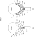
- a pumping function unit 10 is configured of: a diaphragm 11 made of a flexible membrane whose size is set to fit an external shape of a lower heart part of a target person (such as a patient whose cardiac output function has degraded significantly due to a myocardial infarction); four compression balloons 12A to 12D which are respectively pasted at specified positions on an inner wall surface of the diaphragm 11; and a tubular joint 15 that bundles and receives an air supply passage 13, which communicates with an end of the diaphragm 11 and tubes 14A to 14D which are drawn from the respective compression balloons 12A to 12D.
- the tubular joint 15 has a hollow part into which the diaphragm 11 and the respective compression balloons 12A to 12D are collectively stuffed; and the diaphragm 11 and the respective compression balloons 12Ato 12D are designed to expand and be discharged from the top end side of the tubular joint 15 by increasing an air pressure inside the diaphragm 11.
- the respective compression balloons 12A to 12D are pasted respectively at specified positions on an inner wall surface of the diaphragm 11 so that they are positioned opposite right and left atriums and ventricles, respectively, when the lower heart part is covered and wrapped with the diaphragm 11.
- the diaphragm 11 is designed so that its entire membrane flexes according to the air pressure; however, a material with a very low degree of expansion and contraction (that is, a low modulus of elasticity) is selected.
- a material with a very low degree of expansion and contraction that is, a low modulus of elasticity
- examples of a desired material to be selected include organic or inorganic polymeric fiber materials and polymeric conjugated fiber materials which have no property causing damage to a living body. Artificial leather, imitation leather, or synthetic leather can also be applied as long as they have no property causing damage to a living body.
- the respective compression balloons 12A to 12D are formed of, for example, silicone rubber and are designed to expand or contract as caused by water discharged or absorbed via the tubes 14A to 14D from second drive units 23A to 23D ( Fig. 4 ) described later.
- the diaphragm 11 and the respective compression balloons 12A to 12D are stuffed into the hollow part of the tubular joint 15 in advance.
- the diaphragm 11 is stuffed into the hollow part of the tubular joint 15 with reference to a mark assigned to the top end of the tubular joint 15 by defining a positional relationship between the respective compression balloons 12A to 12D; and when locating the top end of the tubular joint 15 at the lower heart part, the mark is positioned in conformity with the positions of the right and left ventricles.
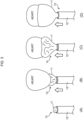
- the pumping function unit 10 when the top end of the tubular joint 15 ( Fig. 3A ), in which the diaphragm 11 and the respective compression balloons 12A to 12D are stuffed, is located at the target person's lower heart part ( Fig. 3B ), the first drive unit 22 ( Fig. 4 ) described later starts to press air into the diaphragm 11 and the lower heart part is gradually covered and wrapped with the diaphragm 11 ( Fig. 3C ).
- the doctor or the like may adjust the positions of the compression balloons 12A to 12D corresponding to the right and left atriums and ventricles under the X-ray environment.
- Fig. 4 illustrates an overall configuration of a cardiac output support apparatus 20.
- the cardiac output support apparatus 20 includes: a control unit 21 that controls the entire apparatus; the pumping function unit 10 that supports the pumping function of the target person's heart; and the first drive unit 22 and the second drive units 23A to 23D that drive the diaphragm 11 and the respective compression balloons 12A to 12D, respectively, of the pumping function unit 10 to make them expand and contract.
- the first drive unit 22 is configured of an air pressure actuator 24 which is composed of a servo motor, and an air compression tank 25; and is driven to press the air into the diaphragm 11 through a tube 26.
- the first drive unit 22 pushes the diaphragm 11 out from the top end of the tubular joint 15 while pressing the air into the diaphragm 11 under the control of the control unit 21 and simultaneously causes the diaphragm 11 to start flexing to cover and wrap the lower heart part; and stops pressing the air into the diaphragm 11 at the time point where the respective compression balloons 12A to 12D are positioned at the right and left ventricles of the heart.
- the second drive units 23A to 23D are provided for the left atrium, the left ventricle, the right atrium, and the right ventricle, respectively, corresponding to the compression balloons 12A to 12D.
- Each of these second drive units 23A to 23D: is configured of, as illustrated in Fig. 5 , an actuator (for the left atrium, the left ventricle, the right atrium, and the right ventricle) 30 which is composed of a servo motor, and a cylinder 31 which is filled with water inside and is capable of reciprocating linear motions; and is driven to eject or absorb water to or from the relevant compression balloon 12A to 12D while adjusting a cardiac output support amount according to angular control of the actuator 30.
- each second drive unit 23A to 23D supports the heart's pumping function by adjusting the timing to control compression or relaxation of the right and left atriums and ventricles of the heart while alternately repeating an ejecting operation to fill the relevant compression balloon 12A to 12D with water and make them expand and an absorbing operation to cause the relevant compression balloon 12A to 12D to discharge the water and contract under the control of the control unit 21.
- the control unit 21 is designed to adjust a water discharge amount and discharge timing from the corresponding cylinder 31 while servo-controlling each actuator 30 in synchronization with the heart beats, so that the blood in a cardiac output volume of 70 [ml] or more for one output in blood circulation of a general adult male's heart can be repeatedly output from the heart.
- the cardiac output support apparatus 20 is provided with an optical arterial blood measurement unit 40 capable of non-invasive measurement through the target person's skin surface when the tubular joint 15 is inserted to near the target person's lower heart part, so that a measurement result is sent to the control unit 21 while measuring the target person's pulse rate and arterial oxygen saturation.
- the control unit 21 controls each second drive unit 23A to 23D on the basis of the measurement result obtained from the arterial blood measurement unit and independently adjusts the cardiac output and the cardiac output cycle with respect to the respective compression balloons 12A to 12D.
- the cardiac output support apparatus 20 can control the respective compression balloons 12A to 12D in accordance with a blood circulation condition of the target person and suppress degradation of the heart's pumping function (the blood receiving function and the blood sending function) while letting the right and left atriums and ventricles of the heart contract or relax.
- the cardiac output support apparatus 20 is provided with a cardiac condition detection unit 41 which has a flexible electrode interposed on an adhesive surface of each compression balloon 12A to 12D relative to the diaphragm 11, so that a detection result is sent to the control unit 21 while detecting a disease condition of the target person's heart.
- the control unit 21 controls each second drive unit 23A to 23D on the basis of the measurement result obtained from the cardiac condition detection unit 41 and controls the respective compression balloons 12A to 12D independently in a specified cardiac output cycle and with specified cardiac output.
- the cardiac output support apparatus 20 can control the sequential order and the degree of compression of the respective compression balloons 12A to 12D in accordance with the disease condition of the target person's heart and suppress degradation of the heart's pumping function while letting the right and left atriums and ventricles of the heart contract or relax.
- a model system which simulates a circulatory system is constructed as a heart model by simulating the degree of hardness of an actual heart, blocking blood vessels of a left heart system other than an aorta and a pulmonary vein, and filling the left heart system with water; and also the heart model in which balloons containing water are inserted in a right ventricle is prepared. Valves of this heart model are simulated to prevent a reverse flow by closing the pulmonary vein when compressing the heart.
- an aorta 50A is closed with a tube clip 51, the left heart system is filled with water, and the heart model 50 is caused to expand. Subsequently, a pulmonary vein 50B is closed with a tube clip 52 and the tube clip 51 of the aorta 50A is released.
- the cardiac output support apparatus 20 according to this embodiment is applied in this state and the respective compression balloons 12A to 12D are compressed against the heart model 50 to cause the water in the heart model 50 to be discharged.
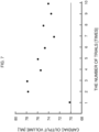
- the cardiac output support apparatus 20 As a result of trying a cardiac output support operation by using this cardiac output support apparatus 20 ten times, an amount of water discharged from the heart model 50 was 70 [ml] or more in all the trials as illustrated in Fig. 7 . According to this experiment result, it has been confirmed by this experiment result that the cardiac output support apparatus 20 according to this embodiment has the performance capable of sufficiently securing the cardiac output volume by the pumping function of the heart model 50.
- the fluid inside the heart is blood, it is predicted that the blood has high viscosity and can hardly be discharged; however, it has already been confirmed that this can be handled by increasing the amount of water to be supplied to each compression balloon.
- the tubular joint in which the diaphragm 11 and the respective compression balloons 12A to 12D are stuffed is inserted into the incised part and is located at the lower heart part.
- control unit 21 controls the first drive unit 22 to: push the diaphragm 11 out from the top end of the tubular joint 15 while pressing the air into the diaphragm 11 and causes the diaphragm 11 to start flexing to cover and wrap the lower heart part; and stop pressing the air into the diaphragm 11 at the time point where the respective compression balloons 12A to 12D are positions at the right and left atriums and ventricles of the heart.
- control unit 21 controls the second drive units 23A to 23D to support the heart's pumping function by alternately repeating the ejecting operation to fill the respective compression balloons 12A to 12D with water and make them expand and the absorbing operation to cause the respective compression balloons 12A to 12D to discharge the water and contract.
- the cardiac output support apparatus 20 can cover and wrap the lower heart part with the diaphragm 11 and simultaneously position the respective compression balloons 12A to 12D by increasing the air pressure inside the diaphragm 1 from outside in the state where the target person's chest is incised along the length approximately equal to the diameter of the tubular joint 15 and the tubular joint 15 is inserted into the incised part.
- the cardiac output support apparatus 20 it becomes no longer necessary to incise the target person's chest along the length equal to or longer than the width of the heart; and, therefore, even a doctor who is not a cardiovascular surgery medical specialist can perform the operation and secure the sufficient amount of blood to the heart and it is possible to minimize damage to the target person's heart.
- this embodiment has described the case where the four compression balloons 12Ato 12D corresponding to the right and left atriums and ventricles are pasted on the diaphragm 11 of the pumping function unit 10 and are respectively independently driven in synchronization with the heart beats; however, the present invention is not limited to this example and only either the compression balloons for the left heart (the left atrium and the left ventricle) or the compression balloons for the right heart (the right atrium and the right ventricle) may be driven.
- the right heart support and the left heart support may be executed or stopped respectively independently by: performing the support of both the hearts if the patient's condition is bad; and switching to the support of only the left heart if the patient's condition is recovering.
- this embodiment has described the case where its entire membrane of the diaphragm 11 flexes according to the air pressure, but a material with a very low degree of expansion and contraction (that is, a low modulus of elasticity) is selected; however, the present invention is not limited to this example and a peripheral region of the diaphragm 11 which does not enter into direct contact with the heart when the diaphragm 11 covers and wraps the lower heart part may be formed of a material with flexibility and non-pliability.
- each compression balloon 12Ato 12D is configured of a material with flexibility and pliability such as silicone rubber; however, the present invention is not limited to this example and a whole or part of the exposed portion of each respective compression balloon 12A to 12D other than its abutting region in contact with the diaphragm 11 may be formed of a material with flexibility and non-pliability.
- this embodiment has described the case where after a part of the chest corresponding to the target person's lower heart part is slightly incised under the normal surgical operation environment, the tubular joint 15 in which the diaphragm 11 and the respective compression balloons 12A to 12D are stuffed is inserted and located at the lower heart part; however, the present invention is not limited to this example and a freely expandable and contractable mesh-like material whose size is set to fit the external shape of the target person's lower heart part may be used to cover and wrap the lower heart part before inserting the tubular joint 15.
- a doctor or the like needs to handle the mesh-like material with their fingertips under the environment by X-ray imaging so that coronary arteries of the target person's lower heart part are exposed through gaps in the mesh-like material, in other words, a mesh fabric of the mesh-like material will not cover the coronary arteries.
- a mesh fabric of the mesh-like material will not cover the coronary arteries.
- this embodiment has described the case where the water which is an incompressible fluid is used as the fluid in the respective compression balloons 12A to 12D; however, the present invention is not limited to this example and any liquid other than the water may be used as long as it is the incompressible fluid regarding which safety for the human body can be secured.
- this embodiment has described the case where the air is applied as the gas which is pressed into the diaphragm 11; however, the present invention is not limited to this example and any gas such as a helium gas may be used as long as it does not affect the human body.
Landscapes
- Health & Medical Sciences (AREA)
- Engineering & Computer Science (AREA)
- Cardiology (AREA)
- Heart & Thoracic Surgery (AREA)
- Life Sciences & Earth Sciences (AREA)
- Anesthesiology (AREA)
- Biomedical Technology (AREA)
- Hematology (AREA)
- Mechanical Engineering (AREA)
- Animal Behavior & Ethology (AREA)
- General Health & Medical Sciences (AREA)
- Public Health (AREA)
- Veterinary Medicine (AREA)
- Vascular Medicine (AREA)
- Medical Informatics (AREA)
- External Artificial Organs (AREA)
Claims (7)
- Appareil d'assistance au débit cardiaque (20) comprenant :un diaphragme (11) dont la taille est réglée pour s'adapter à une forme externe d'une partie inférieure du coeur d'une personne cible et qui est composé d'une membrane flexible qui est sensible à une pression de gaz ;une pluralité de ballonnets de compression (12A à 12D) qui sont mis en adhérence à des positions spécifiées d'une surface de paroi intérieure du diaphragme de sorte que les ballonnets de compression sont positionnés en face des oreillettes et des ventricules du coeur, respectivement, lorsque la partie inférieure du coeur est recouverte et enveloppée avec le diaphragme ;une première unité d'entraînement (22) qui est entraînée pour presser du gaz dans le diaphragme ;des secondes unités d'entraînement (23A à 23D) qui sont entraînées pour éjecter ou aspirer un fluide vers ou depuis les ballonnets de compression, respectivement ; etun joint tubulaire (15) avec une partie creuse dans laquelle le diaphragme et chacun des ballonnets de compression sont disposés à l'avance collectivement, dans lequel la première unité d'entraînement est configurée pour, dans un état où une extrémité supérieure du joint tubulaire est interposée dans la poitrine de la personne cible et est située au niveau de la partie de coeur inférieure, pousser le diaphragme hors de l'extrémité supérieure du joint tubulaire tout en pressant le gaz dans le diaphragme, et pour simultanément amener le diaphragme à commencer à fléchir pour couvrir et envelopper la partie de coeur inférieure, et pour ensuite arrêter de presser le gaz dans le diaphragme à un moment où les ballonnets de compression sont positionnés au niveau des oreillettes et des ventricules du coeur, respectivement ; etdans lequel les secondes unités d'entraînement sont configurées pour supporter un fonctionnement de pompage du coeur par une répétition alternée d'une opération d'éjection pour remplir chacun des ballonnets de compression avec le fluide et amener chaque ballonnet de compression à se dilater et une opération d'aspiration pour amener chaque ballonnet de compression à évacuer le fluide et à se contracter.
- Appareil d'assistance au débit cardiaque selon la revendication 1,
dans lequel une région périphérique du diaphragme qui ne vient pas en contact direct avec le coeur lors du recouvrement et de l'enveloppement de la partie de coeur inférieure est formée d'un matériau présentant une flexibilité et une non-pliabilité. - Appareil d'assistance au débit cardiaque selon la revendication 2,
dans lequel tout ou partie d'une partie exposée de chaque ballonnet de compression autre que sa région de butée en contact avec le diaphragme est formée d'un matériau présentant une flexibilité et une non-pliabilité. - Appareil d'assistance au débit cardiaque selon l'une quelconque des revendications 1 à 3, comprenant en outre une unité de mesure de sang artériel (40) configurée pour mesurer une fréquence cardiaque et une saturation artérielle en oxygène de la personne cible,
dans lequel chacune des secondes unités d'entraînement est configurée pour ajuster indépendamment un débit cardiaque et un cycle de débit cardiaque par rapport à chaque ballonnet de compression conformément à un résultat de mesure de l'unité de mesure de sang artériel. - Appareil d'assistance au débit cardiaque selon l'une quelconque des revendications 1 à 4, comprenant en outre une unité de détection de condition cardiaque (41) configurée pour détecter une condition de maladie du coeur de la personne cible,
dans lequel chacune des secondes unités d'entraînement est configurée pour commander indépendamment chaque ballonnet de compression dans un cycle de débit cardiaque spécifié et avec un débit cardiaque spécifié sur la base d'un état de détection de l'unité de détection de condition cardiaque. - Appareil d'assistance au débit cardiaque selon l'une quelconque des revendications 1 à 5,dans lequel le diaphragme est disposé dans la partie creuse du joint tubulaire par référence à une marque attribuée à l'extrémité supérieure du joint tubulaire en définissant une relation de position entre les ballonnets de compression respectifs ; etlorsque l'extrémité supérieure du joint tubulaire est située au niveau de la partie de coeur inférieure, la marque est positionnée en conformité avec les positions des oreillettes et des ventricules.
- Appareil d'assistance au débit cardiaque selon l'une quelconque des revendications 1 à 6,
dans lequel un matériau de type maillé librement extensible et contractable dont la taille est réglée pour s'adapter à la forme externe de la partie de coeur inférieure de la personne cible est conçu pour recouvrir et envelopper la partie de coeur inférieure de telle sorte que les artères coronaires sont exposées à partir d'espaces sous un environnement d'imagerie par rayons X ; et le diaphragme est conçu pour recouvrir et envelopper davantage une surface du matériau de type maillé.
Applications Claiming Priority (2)
| Application Number | Priority Date | Filing Date | Title |
|---|---|---|---|
| JP2018162211 | 2018-08-30 | ||
| PCT/JP2019/034226 WO2020045654A1 (fr) | 2018-08-30 | 2019-08-30 | Dispositif d'aide au pompage cardiaque |
Publications (3)
| Publication Number | Publication Date |
|---|---|
| EP3845255A1 EP3845255A1 (fr) | 2021-07-07 |
| EP3845255A4 EP3845255A4 (fr) | 2022-05-18 |
| EP3845255B1 true EP3845255B1 (fr) | 2023-03-15 |
Family
ID=69643896
Family Applications (1)
| Application Number | Title | Priority Date | Filing Date |
|---|---|---|---|
| EP19855486.7A Active EP3845255B1 (fr) | 2018-08-30 | 2019-08-30 | Dispositif d'aide au pompage cardiaque |
Country Status (4)
| Country | Link |
|---|---|
| US (1) | US11980751B2 (fr) |
| EP (1) | EP3845255B1 (fr) |
| JP (1) | JP7057925B2 (fr) |
| WO (1) | WO2020045654A1 (fr) |
Families Citing this family (3)
| Publication number | Priority date | Publication date | Assignee | Title |
|---|---|---|---|---|
| KR101695674B1 (ko) * | 2015-07-17 | 2017-01-12 | 배병철 | 레일간 도상 제거장치 |
| WO2023212148A1 (fr) * | 2022-04-28 | 2023-11-02 | Corinnova Incorporated | Procédé et dispositif d'optimisation de la charge d'un dispositif d'assistance cardiaque |
| JPWO2024154532A1 (fr) * | 2023-01-18 | 2024-07-25 |
Family Cites Families (26)
| Publication number | Priority date | Publication date | Assignee | Title |
|---|---|---|---|---|
| US4690134A (en) * | 1985-07-01 | 1987-09-01 | Snyders Robert V | Ventricular assist device |
| ES2121857T3 (es) * | 1992-05-19 | 1998-12-16 | Cardio Tech Inc | Copa para masaje cardiaco ventricular y aparato que la incorpora. |
| JPH10174713A (ja) * | 1996-12-17 | 1998-06-30 | Buaayu:Kk | 心臓補助装置 |
| JP3935541B2 (ja) * | 1996-12-17 | 2007-06-27 | 株式会社ヴァーユ | 心臓補助装置 |
| US6063115A (en) * | 1997-04-11 | 2000-05-16 | Medtronic, Inc. | Cardiac assistance system |
| US6095968A (en) * | 1998-04-10 | 2000-08-01 | Cardio Technologies, Inc. | Reinforcement device |
| AU8126898A (en) * | 1998-07-07 | 2000-01-24 | Pulsecare Ltd. | Minimal invasive cardiac massage device |
| US6432039B1 (en) * | 1998-12-21 | 2002-08-13 | Corset, Inc. | Methods and apparatus for reinforcement of the heart ventricles |
| US6540659B1 (en) * | 2000-11-28 | 2003-04-01 | Abiomed, Inc. | Cardiac assistance systems having bi-directional pumping elements |
| US7860555B2 (en) | 2005-02-02 | 2010-12-28 | Voyage Medical, Inc. | Tissue visualization and manipulation system |
| CN101336119A (zh) * | 2005-11-28 | 2008-12-31 | 米奥特克有限责任公司 | 用于微创直接机械式心室促动的方法和装置 |
| EP2229213A4 (fr) * | 2008-01-08 | 2012-10-17 | Univ Nat Cheng Kung | Système de compression cardiaque |
| SG195610A1 (en) | 2008-09-15 | 2013-12-30 | Aeeg Ab | Medical device, method and system for temporary occlusion of an opening in a lumen of a body |
| EP2349096B1 (fr) | 2008-10-10 | 2021-01-27 | MedicalTree Patent Ltd. | Valvule artificielle perfectionnée |
| AU2009302945C1 (en) | 2008-10-10 | 2016-04-21 | Medicaltree Patent Ltd | Heart help device, system, and method |
| US8523756B2 (en) * | 2008-12-31 | 2013-09-03 | National Cheng Kung University | Cardiac compression system |
| JP5716024B2 (ja) * | 2009-07-22 | 2015-05-13 | ザ テキサス エー アンド エム ユニヴァーシティー システムThe Texas A&M University System | 心臓病態を治療するための補助及びリコイル機能を備える二相性及び動的調整可能サポートデバイス及び方法 |
| DE102013200154A1 (de) * | 2013-01-08 | 2014-07-10 | AdjuCor GmbH | Herzunterstützungsvorrichtung mit einer Schale und einer ersten und einer zweiten Hülle |
| DE102013200151A1 (de) * | 2013-01-08 | 2014-07-10 | AdjuCor GmbH | Herzunterstützungsvorrichtung mit Markierungen |
| US9220824B2 (en) * | 2013-01-08 | 2015-12-29 | AdjuCor GmbH | Implanting cardiac devices |
| DE102013200149A1 (de) * | 2013-01-08 | 2014-07-24 | AdjuCor GmbH | Herzunterstützungsvorrichtung mit einer Kammer mit einem balgförmigen Abschnitt |
| DE102013200148B4 (de) * | 2013-01-08 | 2026-01-08 | AdjuCor GmbH | Steckersystem für eine Herzunterstützungsvorrichtung |
| JP6773953B2 (ja) * | 2015-02-19 | 2020-10-21 | 学校法人 久留米大学 | 補助心臓装置 |
| US10463496B2 (en) * | 2015-07-15 | 2019-11-05 | The Texas A&M University System | Self-expanding heart assist device |
| WO2017223485A1 (fr) * | 2016-06-23 | 2017-12-28 | The Texas A&M University System | Dispositif d'assistance myocardique directe entièrement implantable |
| US11382752B2 (en) * | 2019-01-18 | 2022-07-12 | Rex Medical, L.P. | Minnimally invasive device for treating chronic heart failure |
-
2019
- 2019-08-30 JP JP2020539645A patent/JP7057925B2/ja active Active
- 2019-08-30 WO PCT/JP2019/034226 patent/WO2020045654A1/fr not_active Ceased
- 2019-08-30 EP EP19855486.7A patent/EP3845255B1/fr active Active
- 2019-08-30 US US17/271,968 patent/US11980751B2/en active Active
Also Published As
| Publication number | Publication date |
|---|---|
| WO2020045654A1 (fr) | 2020-03-05 |
| EP3845255A1 (fr) | 2021-07-07 |
| US11980751B2 (en) | 2024-05-14 |
| EP3845255A4 (fr) | 2022-05-18 |
| JPWO2020045654A1 (ja) | 2021-08-12 |
| US20210338998A1 (en) | 2021-11-04 |
| JP7057925B2 (ja) | 2022-04-21 |
Similar Documents
| Publication | Publication Date | Title |
|---|---|---|
| US10058647B2 (en) | Biomimetic actuation device and system, and methods for controlling a biomimetic actuation device and system | |
| JP4871917B2 (ja) | 心臓補助システム | |
| RU2703701C2 (ru) | Поддерживающее сердце устройство | |
| US10376681B2 (en) | Vacuum-based compliance restoration | |
| US6918870B1 (en) | Assist device for the failing heart | |
| EP2785393B1 (fr) | Dispositif mécanique sans contact avec le sang permettant d'améliorer la fonction cardiaque après une lésion | |
| CN102107030B (zh) | 心脏搏动辅助装置、心脏搏动辅助系统、以及治疗心力衰竭的方法 | |
| EP3845255B1 (fr) | Dispositif d'aide au pompage cardiaque | |
| EP1140248A2 (fr) | Procede et appareil renfor ant les ventricules cardiaques | |
| WO2011100180A1 (fr) | Activation ventriculaire différentielle extracardiaque par le biais de séparations par inertie et barique | |
| US6149578A (en) | Piston-action intra-aortic coronary assist device | |
| US20170258593A1 (en) | Cardiac assistance device | |
| EP3651826B1 (fr) | Pompe intracardiaque | |
| US8523756B2 (en) | Cardiac compression system | |
| US20060178604A1 (en) | Blood pumping system | |
| WO2009088916A1 (fr) | Système de compression cardiaque | |
| US8142372B2 (en) | External left ventricular assist device for treatment of congestive heart failure | |
| WO1998030271A1 (fr) | Dispositif de traitement cardiaque | |
| CN201572358U (zh) | 心脏搏动辅助装置以及心脏搏动辅助系统 | |
| US20080242916A1 (en) | Eecp Device and an Image System Comprising the Same | |
| US20190209759A1 (en) | Ventricular assist devices | |
| AU742406B2 (en) | An assist device for the failing heart | |
| JPWO1993020861A1 (ja) | 体内式心臓補助装置 |
Legal Events
| Date | Code | Title | Description |
|---|---|---|---|
| STAA | Information on the status of an ep patent application or granted ep patent |
Free format text: STATUS: THE INTERNATIONAL PUBLICATION HAS BEEN MADE |
|
| STAA | Information on the status of an ep patent application or granted ep patent |
Free format text: STATUS: REQUEST FOR EXAMINATION WAS MADE |
|
| PUAI | Public reference made under article 153(3) epc to a published international application that has entered the european phase |
Free format text: ORIGINAL CODE: 0009012 |
|
| 17P | Request for examination filed |
Effective date: 20210316 |
|
| AK | Designated contracting states |
Kind code of ref document: A1 Designated state(s): AL AT BE BG CH CY CZ DE DK EE ES FI FR GB GR HR HU IE IS IT LI LT LU LV MC MK MT NL NO PL PT RO RS SE SI SK SM TR |
|
| DAV | Request for validation of the european patent (deleted) | ||
| DAX | Request for extension of the european patent (deleted) | ||
| A4 | Supplementary search report drawn up and despatched |
Effective date: 20220422 |
|
| RIC1 | Information provided on ipc code assigned before grant |
Ipc: A61M 60/865 20210101ALI20220414BHEP Ipc: A61M 60/839 20210101ALI20220414BHEP Ipc: A61M 60/515 20210101ALI20220414BHEP Ipc: A61M 60/468 20210101ALI20220414BHEP Ipc: A61M 60/289 20210101ALI20220414BHEP Ipc: A61M 60/191 20210101AFI20220414BHEP |
|
| REG | Reference to a national code |
Ref country code: DE Ref legal event code: R079 Ref document number: 602019026520 Country of ref document: DE Free format text: PREVIOUS MAIN CLASS: A61M0001100000 Ipc: A61M0060191000 |
|
| GRAP | Despatch of communication of intention to grant a patent |
Free format text: ORIGINAL CODE: EPIDOSNIGR1 |
|
| RIC1 | Information provided on ipc code assigned before grant |
Ipc: A61M 60/865 20210101ALI20220916BHEP Ipc: A61M 60/839 20210101ALI20220916BHEP Ipc: A61M 60/515 20210101ALI20220916BHEP Ipc: A61M 60/468 20210101ALI20220916BHEP Ipc: A61M 60/289 20210101ALI20220916BHEP Ipc: A61M 60/191 20210101AFI20220916BHEP |
|
| STAA | Information on the status of an ep patent application or granted ep patent |
Free format text: STATUS: GRANT OF PATENT IS INTENDED |
|
| INTG | Intention to grant announced |
Effective date: 20221027 |
|
| GRAS | Grant fee paid |
Free format text: ORIGINAL CODE: EPIDOSNIGR3 |
|
| GRAA | (expected) grant |
Free format text: ORIGINAL CODE: 0009210 |
|
| STAA | Information on the status of an ep patent application or granted ep patent |
Free format text: STATUS: THE PATENT HAS BEEN GRANTED |
|
| AK | Designated contracting states |
Kind code of ref document: B1 Designated state(s): AL AT BE BG CH CY CZ DE DK EE ES FI FR GB GR HR HU IE IS IT LI LT LU LV MC MK MT NL NO PL PT RO RS SE SI SK SM TR |
|
| REG | Reference to a national code |
Ref country code: CH Ref legal event code: EP Ref country code: GB Ref legal event code: FG4D |
|
| REG | Reference to a national code |
Ref country code: DE Ref legal event code: R096 Ref document number: 602019026520 Country of ref document: DE |
|
| REG | Reference to a national code |
Ref country code: IE Ref legal event code: FG4D |
|
| REG | Reference to a national code |
Ref country code: AT Ref legal event code: REF Ref document number: 1553640 Country of ref document: AT Kind code of ref document: T Effective date: 20230415 |
|
| REG | Reference to a national code |
Ref country code: LT Ref legal event code: MG9D |
|
| REG | Reference to a national code |
Ref country code: NL Ref legal event code: MP Effective date: 20230315 |
|
| PG25 | Lapsed in a contracting state [announced via postgrant information from national office to epo] |
Ref country code: RS Free format text: LAPSE BECAUSE OF FAILURE TO SUBMIT A TRANSLATION OF THE DESCRIPTION OR TO PAY THE FEE WITHIN THE PRESCRIBED TIME-LIMIT Effective date: 20230315 Ref country code: NO Free format text: LAPSE BECAUSE OF FAILURE TO SUBMIT A TRANSLATION OF THE DESCRIPTION OR TO PAY THE FEE WITHIN THE PRESCRIBED TIME-LIMIT Effective date: 20230615 Ref country code: LV Free format text: LAPSE BECAUSE OF FAILURE TO SUBMIT A TRANSLATION OF THE DESCRIPTION OR TO PAY THE FEE WITHIN THE PRESCRIBED TIME-LIMIT Effective date: 20230315 Ref country code: LT Free format text: LAPSE BECAUSE OF FAILURE TO SUBMIT A TRANSLATION OF THE DESCRIPTION OR TO PAY THE FEE WITHIN THE PRESCRIBED TIME-LIMIT Effective date: 20230315 Ref country code: HR Free format text: LAPSE BECAUSE OF FAILURE TO SUBMIT A TRANSLATION OF THE DESCRIPTION OR TO PAY THE FEE WITHIN THE PRESCRIBED TIME-LIMIT Effective date: 20230315 |
|
| REG | Reference to a national code |
Ref country code: AT Ref legal event code: MK05 Ref document number: 1553640 Country of ref document: AT Kind code of ref document: T Effective date: 20230315 |
|
| PG25 | Lapsed in a contracting state [announced via postgrant information from national office to epo] |
Ref country code: SE Free format text: LAPSE BECAUSE OF FAILURE TO SUBMIT A TRANSLATION OF THE DESCRIPTION OR TO PAY THE FEE WITHIN THE PRESCRIBED TIME-LIMIT Effective date: 20230315 Ref country code: NL Free format text: LAPSE BECAUSE OF FAILURE TO SUBMIT A TRANSLATION OF THE DESCRIPTION OR TO PAY THE FEE WITHIN THE PRESCRIBED TIME-LIMIT Effective date: 20230315 Ref country code: GR Free format text: LAPSE BECAUSE OF FAILURE TO SUBMIT A TRANSLATION OF THE DESCRIPTION OR TO PAY THE FEE WITHIN THE PRESCRIBED TIME-LIMIT Effective date: 20230616 Ref country code: FI Free format text: LAPSE BECAUSE OF FAILURE TO SUBMIT A TRANSLATION OF THE DESCRIPTION OR TO PAY THE FEE WITHIN THE PRESCRIBED TIME-LIMIT Effective date: 20230315 |
|
| PG25 | Lapsed in a contracting state [announced via postgrant information from national office to epo] |
Ref country code: SM Free format text: LAPSE BECAUSE OF FAILURE TO SUBMIT A TRANSLATION OF THE DESCRIPTION OR TO PAY THE FEE WITHIN THE PRESCRIBED TIME-LIMIT Effective date: 20230315 Ref country code: RO Free format text: LAPSE BECAUSE OF FAILURE TO SUBMIT A TRANSLATION OF THE DESCRIPTION OR TO PAY THE FEE WITHIN THE PRESCRIBED TIME-LIMIT Effective date: 20230315 Ref country code: PT Free format text: LAPSE BECAUSE OF FAILURE TO SUBMIT A TRANSLATION OF THE DESCRIPTION OR TO PAY THE FEE WITHIN THE PRESCRIBED TIME-LIMIT Effective date: 20230717 Ref country code: ES Free format text: LAPSE BECAUSE OF FAILURE TO SUBMIT A TRANSLATION OF THE DESCRIPTION OR TO PAY THE FEE WITHIN THE PRESCRIBED TIME-LIMIT Effective date: 20230315 Ref country code: EE Free format text: LAPSE BECAUSE OF FAILURE TO SUBMIT A TRANSLATION OF THE DESCRIPTION OR TO PAY THE FEE WITHIN THE PRESCRIBED TIME-LIMIT Effective date: 20230315 Ref country code: CZ Free format text: LAPSE BECAUSE OF FAILURE TO SUBMIT A TRANSLATION OF THE DESCRIPTION OR TO PAY THE FEE WITHIN THE PRESCRIBED TIME-LIMIT Effective date: 20230315 Ref country code: AT Free format text: LAPSE BECAUSE OF FAILURE TO SUBMIT A TRANSLATION OF THE DESCRIPTION OR TO PAY THE FEE WITHIN THE PRESCRIBED TIME-LIMIT Effective date: 20230315 |
|
| PG25 | Lapsed in a contracting state [announced via postgrant information from national office to epo] |
Ref country code: SK Free format text: LAPSE BECAUSE OF FAILURE TO SUBMIT A TRANSLATION OF THE DESCRIPTION OR TO PAY THE FEE WITHIN THE PRESCRIBED TIME-LIMIT Effective date: 20230315 Ref country code: PL Free format text: LAPSE BECAUSE OF FAILURE TO SUBMIT A TRANSLATION OF THE DESCRIPTION OR TO PAY THE FEE WITHIN THE PRESCRIBED TIME-LIMIT Effective date: 20230315 Ref country code: IS Free format text: LAPSE BECAUSE OF FAILURE TO SUBMIT A TRANSLATION OF THE DESCRIPTION OR TO PAY THE FEE WITHIN THE PRESCRIBED TIME-LIMIT Effective date: 20230715 |
|
| REG | Reference to a national code |
Ref country code: DE Ref legal event code: R097 Ref document number: 602019026520 Country of ref document: DE |
|
| PLBE | No opposition filed within time limit |
Free format text: ORIGINAL CODE: 0009261 |
|
| STAA | Information on the status of an ep patent application or granted ep patent |
Free format text: STATUS: NO OPPOSITION FILED WITHIN TIME LIMIT |
|
| PG25 | Lapsed in a contracting state [announced via postgrant information from national office to epo] |
Ref country code: SI Free format text: LAPSE BECAUSE OF FAILURE TO SUBMIT A TRANSLATION OF THE DESCRIPTION OR TO PAY THE FEE WITHIN THE PRESCRIBED TIME-LIMIT Effective date: 20230315 Ref country code: DK Free format text: LAPSE BECAUSE OF FAILURE TO SUBMIT A TRANSLATION OF THE DESCRIPTION OR TO PAY THE FEE WITHIN THE PRESCRIBED TIME-LIMIT Effective date: 20230315 |
|
| 26N | No opposition filed |
Effective date: 20231218 |
|
| PG25 | Lapsed in a contracting state [announced via postgrant information from national office to epo] |
Ref country code: MC Free format text: LAPSE BECAUSE OF FAILURE TO SUBMIT A TRANSLATION OF THE DESCRIPTION OR TO PAY THE FEE WITHIN THE PRESCRIBED TIME-LIMIT Effective date: 20230315 |
|
| REG | Reference to a national code |
Ref country code: CH Ref legal event code: PL |
|
| PG25 | Lapsed in a contracting state [announced via postgrant information from national office to epo] |
Ref country code: MC Free format text: LAPSE BECAUSE OF FAILURE TO SUBMIT A TRANSLATION OF THE DESCRIPTION OR TO PAY THE FEE WITHIN THE PRESCRIBED TIME-LIMIT Effective date: 20230315 |
|
| PG25 | Lapsed in a contracting state [announced via postgrant information from national office to epo] |
Ref country code: LU Free format text: LAPSE BECAUSE OF NON-PAYMENT OF DUE FEES Effective date: 20230830 |
|
| PG25 | Lapsed in a contracting state [announced via postgrant information from national office to epo] |
Ref country code: LU Free format text: LAPSE BECAUSE OF NON-PAYMENT OF DUE FEES Effective date: 20230830 Ref country code: CH Free format text: LAPSE BECAUSE OF NON-PAYMENT OF DUE FEES Effective date: 20230831 |
|
| REG | Reference to a national code |
Ref country code: BE Ref legal event code: MM Effective date: 20230831 |
|
| REG | Reference to a national code |
Ref country code: IE Ref legal event code: MM4A |
|
| PG25 | Lapsed in a contracting state [announced via postgrant information from national office to epo] |
Ref country code: IE Free format text: LAPSE BECAUSE OF NON-PAYMENT OF DUE FEES Effective date: 20230830 |
|
| PG25 | Lapsed in a contracting state [announced via postgrant information from national office to epo] |
Ref country code: IE Free format text: LAPSE BECAUSE OF NON-PAYMENT OF DUE FEES Effective date: 20230830 Ref country code: FR Free format text: LAPSE BECAUSE OF NON-PAYMENT OF DUE FEES Effective date: 20230831 |
|
| PG25 | Lapsed in a contracting state [announced via postgrant information from national office to epo] |
Ref country code: BE Free format text: LAPSE BECAUSE OF NON-PAYMENT OF DUE FEES Effective date: 20230831 |
|
| PG25 | Lapsed in a contracting state [announced via postgrant information from national office to epo] |
Ref country code: BG Free format text: LAPSE BECAUSE OF FAILURE TO SUBMIT A TRANSLATION OF THE DESCRIPTION OR TO PAY THE FEE WITHIN THE PRESCRIBED TIME-LIMIT Effective date: 20230315 |
|
| PG25 | Lapsed in a contracting state [announced via postgrant information from national office to epo] |
Ref country code: BG Free format text: LAPSE BECAUSE OF FAILURE TO SUBMIT A TRANSLATION OF THE DESCRIPTION OR TO PAY THE FEE WITHIN THE PRESCRIBED TIME-LIMIT Effective date: 20230315 |
|
| PG25 | Lapsed in a contracting state [announced via postgrant information from national office to epo] |
Ref country code: CY Free format text: LAPSE BECAUSE OF FAILURE TO SUBMIT A TRANSLATION OF THE DESCRIPTION OR TO PAY THE FEE WITHIN THE PRESCRIBED TIME-LIMIT; INVALID AB INITIO Effective date: 20190830 |
|
| PG25 | Lapsed in a contracting state [announced via postgrant information from national office to epo] |
Ref country code: HU Free format text: LAPSE BECAUSE OF FAILURE TO SUBMIT A TRANSLATION OF THE DESCRIPTION OR TO PAY THE FEE WITHIN THE PRESCRIBED TIME-LIMIT; INVALID AB INITIO Effective date: 20190830 |
|
| PGFP | Annual fee paid to national office [announced via postgrant information from national office to epo] |
Ref country code: DE Payment date: 20250819 Year of fee payment: 7 |
|
| PGFP | Annual fee paid to national office [announced via postgrant information from national office to epo] |
Ref country code: IT Payment date: 20250821 Year of fee payment: 7 |
|
| PGFP | Annual fee paid to national office [announced via postgrant information from national office to epo] |
Ref country code: GB Payment date: 20250818 Year of fee payment: 7 |
|
| PG25 | Lapsed in a contracting state [announced via postgrant information from national office to epo] |
Ref country code: TR Free format text: LAPSE BECAUSE OF FAILURE TO SUBMIT A TRANSLATION OF THE DESCRIPTION OR TO PAY THE FEE WITHIN THE PRESCRIBED TIME-LIMIT Effective date: 20230315 |