EP3845256B1 - Dispositif de purification du sang - Google Patents
Dispositif de purification du sang Download PDFInfo
- Publication number
- EP3845256B1 EP3845256B1 EP19855616.9A EP19855616A EP3845256B1 EP 3845256 B1 EP3845256 B1 EP 3845256B1 EP 19855616 A EP19855616 A EP 19855616A EP 3845256 B1 EP3845256 B1 EP 3845256B1
- Authority
- EP
- European Patent Office
- Prior art keywords
- tube
- pump
- purification device
- pressing member
- blood purification
- Prior art date
- Legal status (The legal status is an assumption and is not a legal conclusion. Google has not performed a legal analysis and makes no representation as to the accuracy of the status listed.)
- Active
Links
Images












Classifications
-
- A—HUMAN NECESSITIES
- A61—MEDICAL OR VETERINARY SCIENCE; HYGIENE
- A61M—DEVICES FOR INTRODUCING MEDIA INTO, OR ONTO, THE BODY; DEVICES FOR TRANSDUCING BODY MEDIA OR FOR TAKING MEDIA FROM THE BODY; DEVICES FOR PRODUCING OR ENDING SLEEP OR STUPOR
- A61M1/00—Suction or pumping devices for medical purposes; Devices for carrying-off, for treatment of, or for carrying-over, body-liquids; Drainage systems
- A61M1/14—Dialysis systems; Artificial kidneys; Blood oxygenators ; Reciprocating systems for treatment of body fluids, e.g. single needle systems for hemofiltration or pheresis
- A61M1/15—Dialysis systems; Artificial kidneys; Blood oxygenators ; Reciprocating systems for treatment of body fluids, e.g. single needle systems for hemofiltration or pheresis with a cassette forming partially or totally the flow circuit for the treating fluid, e.g. the dialysate fluid circuit or the treating gas circuit
- A61M1/156—Constructional details of the cassette, e.g. specific details on material or shape
- A61M1/1563—Details of incorporated filters
- A61M1/15632—Details of incorporated filters the filter being a dialyser
-
- A—HUMAN NECESSITIES
- A61—MEDICAL OR VETERINARY SCIENCE; HYGIENE
- A61M—DEVICES FOR INTRODUCING MEDIA INTO, OR ONTO, THE BODY; DEVICES FOR TRANSDUCING BODY MEDIA OR FOR TAKING MEDIA FROM THE BODY; DEVICES FOR PRODUCING OR ENDING SLEEP OR STUPOR
- A61M1/00—Suction or pumping devices for medical purposes; Devices for carrying-off, for treatment of, or for carrying-over, body-liquids; Drainage systems
- A61M1/14—Dialysis systems; Artificial kidneys; Blood oxygenators ; Reciprocating systems for treatment of body fluids, e.g. single needle systems for hemofiltration or pheresis
- A61M1/16—Dialysis systems; Artificial kidneys; Blood oxygenators ; Reciprocating systems for treatment of body fluids, e.g. single needle systems for hemofiltration or pheresis with membranes
-
- A—HUMAN NECESSITIES
- A61—MEDICAL OR VETERINARY SCIENCE; HYGIENE
- A61M—DEVICES FOR INTRODUCING MEDIA INTO, OR ONTO, THE BODY; DEVICES FOR TRANSDUCING BODY MEDIA OR FOR TAKING MEDIA FROM THE BODY; DEVICES FOR PRODUCING OR ENDING SLEEP OR STUPOR
- A61M1/00—Suction or pumping devices for medical purposes; Devices for carrying-off, for treatment of, or for carrying-over, body-liquids; Drainage systems
- A61M1/36—Other treatment of blood in a by-pass of the natural circulatory system, e.g. temperature adaptation, irradiation ; Extra-corporeal blood circuits
- A61M1/3621—Extra-corporeal blood circuits
-
- A—HUMAN NECESSITIES
- A61—MEDICAL OR VETERINARY SCIENCE; HYGIENE
- A61M—DEVICES FOR INTRODUCING MEDIA INTO, OR ONTO, THE BODY; DEVICES FOR TRANSDUCING BODY MEDIA OR FOR TAKING MEDIA FROM THE BODY; DEVICES FOR PRODUCING OR ENDING SLEEP OR STUPOR
- A61M1/00—Suction or pumping devices for medical purposes; Devices for carrying-off, for treatment of, or for carrying-over, body-liquids; Drainage systems
- A61M1/36—Other treatment of blood in a by-pass of the natural circulatory system, e.g. temperature adaptation, irradiation ; Extra-corporeal blood circuits
- A61M1/3621—Extra-corporeal blood circuits
- A61M1/3622—Extra-corporeal blood circuits with a cassette forming partially or totally the blood circuit
- A61M1/36222—Details related to the interface between cassette and machine
- A61M1/362227—Details related to the interface between cassette and machine the interface providing means for actuating on functional elements of the cassette, e.g. plungers
-
- A—HUMAN NECESSITIES
- A61—MEDICAL OR VETERINARY SCIENCE; HYGIENE
- A61M—DEVICES FOR INTRODUCING MEDIA INTO, OR ONTO, THE BODY; DEVICES FOR TRANSDUCING BODY MEDIA OR FOR TAKING MEDIA FROM THE BODY; DEVICES FOR PRODUCING OR ENDING SLEEP OR STUPOR
- A61M1/00—Suction or pumping devices for medical purposes; Devices for carrying-off, for treatment of, or for carrying-over, body-liquids; Drainage systems
- A61M1/36—Other treatment of blood in a by-pass of the natural circulatory system, e.g. temperature adaptation, irradiation ; Extra-corporeal blood circuits
- A61M1/3621—Extra-corporeal blood circuits
- A61M1/3622—Extra-corporeal blood circuits with a cassette forming partially or totally the blood circuit
- A61M1/36225—Extra-corporeal blood circuits with a cassette forming partially or totally the blood circuit with blood pumping means or components thereof
-
- A—HUMAN NECESSITIES
- A61—MEDICAL OR VETERINARY SCIENCE; HYGIENE
- A61M—DEVICES FOR INTRODUCING MEDIA INTO, OR ONTO, THE BODY; DEVICES FOR TRANSDUCING BODY MEDIA OR FOR TAKING MEDIA FROM THE BODY; DEVICES FOR PRODUCING OR ENDING SLEEP OR STUPOR
- A61M60/00—Blood pumps; Devices for mechanical circulatory actuation; Balloon pumps for circulatory assistance
- A61M60/10—Location thereof with respect to the patient's body
- A61M60/104—Extracorporeal pumps, i.e. the blood being pumped outside the patient's body
- A61M60/109—Extracorporeal pumps, i.e. the blood being pumped outside the patient's body incorporated within extracorporeal blood circuits or systems
- A61M60/113—Extracorporeal pumps, i.e. the blood being pumped outside the patient's body incorporated within extracorporeal blood circuits or systems in other functional devices, e.g. dialysers or heart-lung machines
-
- A—HUMAN NECESSITIES
- A61—MEDICAL OR VETERINARY SCIENCE; HYGIENE
- A61M—DEVICES FOR INTRODUCING MEDIA INTO, OR ONTO, THE BODY; DEVICES FOR TRANSDUCING BODY MEDIA OR FOR TAKING MEDIA FROM THE BODY; DEVICES FOR PRODUCING OR ENDING SLEEP OR STUPOR
- A61M60/00—Blood pumps; Devices for mechanical circulatory actuation; Balloon pumps for circulatory assistance
- A61M60/20—Type thereof
- A61M60/247—Positive displacement blood pumps
- A61M60/253—Positive displacement blood pumps including a displacement member directly acting on the blood
- A61M60/268—Positive displacement blood pumps including a displacement member directly acting on the blood the displacement member being flexible, e.g. membranes, diaphragms or bladders
- A61M60/279—Peristaltic pumps, e.g. roller pumps
-
- A—HUMAN NECESSITIES
- A61—MEDICAL OR VETERINARY SCIENCE; HYGIENE
- A61M—DEVICES FOR INTRODUCING MEDIA INTO, OR ONTO, THE BODY; DEVICES FOR TRANSDUCING BODY MEDIA OR FOR TAKING MEDIA FROM THE BODY; DEVICES FOR PRODUCING OR ENDING SLEEP OR STUPOR
- A61M60/00—Blood pumps; Devices for mechanical circulatory actuation; Balloon pumps for circulatory assistance
- A61M60/30—Medical purposes thereof other than the enhancement of the cardiac output
- A61M60/36—Medical purposes thereof other than the enhancement of the cardiac output for specific blood treatment; for specific therapy
- A61M60/37—Haemodialysis, haemofiltration or diafiltration
-
- A—HUMAN NECESSITIES
- A61—MEDICAL OR VETERINARY SCIENCE; HYGIENE
- A61M—DEVICES FOR INTRODUCING MEDIA INTO, OR ONTO, THE BODY; DEVICES FOR TRANSDUCING BODY MEDIA OR FOR TAKING MEDIA FROM THE BODY; DEVICES FOR PRODUCING OR ENDING SLEEP OR STUPOR
- A61M60/00—Blood pumps; Devices for mechanical circulatory actuation; Balloon pumps for circulatory assistance
- A61M60/40—Details relating to driving
- A61M60/424—Details relating to driving for positive displacement blood pumps
- A61M60/438—Details relating to driving for positive displacement blood pumps the force acting on the blood contacting member being mechanical
- A61M60/441—Details relating to driving for positive displacement blood pumps the force acting on the blood contacting member being mechanical generated by an electromotor
-
- A—HUMAN NECESSITIES
- A61—MEDICAL OR VETERINARY SCIENCE; HYGIENE
- A61M—DEVICES FOR INTRODUCING MEDIA INTO, OR ONTO, THE BODY; DEVICES FOR TRANSDUCING BODY MEDIA OR FOR TAKING MEDIA FROM THE BODY; DEVICES FOR PRODUCING OR ENDING SLEEP OR STUPOR
- A61M60/00—Blood pumps; Devices for mechanical circulatory actuation; Balloon pumps for circulatory assistance
- A61M60/80—Constructional details other than related to driving
- A61M60/845—Constructional details other than related to driving of extracorporeal blood pumps
- A61M60/847—Constructional details other than related to driving of extracorporeal blood pumps arranged in a cassette
-
- A—HUMAN NECESSITIES
- A61—MEDICAL OR VETERINARY SCIENCE; HYGIENE
- A61M—DEVICES FOR INTRODUCING MEDIA INTO, OR ONTO, THE BODY; DEVICES FOR TRANSDUCING BODY MEDIA OR FOR TAKING MEDIA FROM THE BODY; DEVICES FOR PRODUCING OR ENDING SLEEP OR STUPOR
- A61M1/00—Suction or pumping devices for medical purposes; Devices for carrying-off, for treatment of, or for carrying-over, body-liquids; Drainage systems
- A61M1/14—Dialysis systems; Artificial kidneys; Blood oxygenators ; Reciprocating systems for treatment of body fluids, e.g. single needle systems for hemofiltration or pheresis
- A61M1/15—Dialysis systems; Artificial kidneys; Blood oxygenators ; Reciprocating systems for treatment of body fluids, e.g. single needle systems for hemofiltration or pheresis with a cassette forming partially or totally the flow circuit for the treating fluid, e.g. the dialysate fluid circuit or the treating gas circuit
- A61M1/155—Dialysis systems; Artificial kidneys; Blood oxygenators ; Reciprocating systems for treatment of body fluids, e.g. single needle systems for hemofiltration or pheresis with a cassette forming partially or totally the flow circuit for the treating fluid, e.g. the dialysate fluid circuit or the treating gas circuit with treatment-fluid pumping means or components thereof
-
- A—HUMAN NECESSITIES
- A61—MEDICAL OR VETERINARY SCIENCE; HYGIENE
- A61M—DEVICES FOR INTRODUCING MEDIA INTO, OR ONTO, THE BODY; DEVICES FOR TRANSDUCING BODY MEDIA OR FOR TAKING MEDIA FROM THE BODY; DEVICES FOR PRODUCING OR ENDING SLEEP OR STUPOR
- A61M1/00—Suction or pumping devices for medical purposes; Devices for carrying-off, for treatment of, or for carrying-over, body-liquids; Drainage systems
- A61M1/14—Dialysis systems; Artificial kidneys; Blood oxygenators ; Reciprocating systems for treatment of body fluids, e.g. single needle systems for hemofiltration or pheresis
- A61M1/15—Dialysis systems; Artificial kidneys; Blood oxygenators ; Reciprocating systems for treatment of body fluids, e.g. single needle systems for hemofiltration or pheresis with a cassette forming partially or totally the flow circuit for the treating fluid, e.g. the dialysate fluid circuit or the treating gas circuit
- A61M1/156—Constructional details of the cassette, e.g. specific details on material or shape
- A61M1/1562—Details of incorporated reservoirs
-
- A—HUMAN NECESSITIES
- A61—MEDICAL OR VETERINARY SCIENCE; HYGIENE
- A61M—DEVICES FOR INTRODUCING MEDIA INTO, OR ONTO, THE BODY; DEVICES FOR TRANSDUCING BODY MEDIA OR FOR TAKING MEDIA FROM THE BODY; DEVICES FOR PRODUCING OR ENDING SLEEP OR STUPOR
- A61M1/00—Suction or pumping devices for medical purposes; Devices for carrying-off, for treatment of, or for carrying-over, body-liquids; Drainage systems
- A61M1/14—Dialysis systems; Artificial kidneys; Blood oxygenators ; Reciprocating systems for treatment of body fluids, e.g. single needle systems for hemofiltration or pheresis
- A61M1/16—Dialysis systems; Artificial kidneys; Blood oxygenators ; Reciprocating systems for treatment of body fluids, e.g. single needle systems for hemofiltration or pheresis with membranes
- A61M1/1694—Dialysis systems; Artificial kidneys; Blood oxygenators ; Reciprocating systems for treatment of body fluids, e.g. single needle systems for hemofiltration or pheresis with membranes with recirculating dialysing liquid
- A61M1/1696—Dialysis systems; Artificial kidneys; Blood oxygenators ; Reciprocating systems for treatment of body fluids, e.g. single needle systems for hemofiltration or pheresis with membranes with recirculating dialysing liquid with dialysate regeneration
-
- A—HUMAN NECESSITIES
- A61—MEDICAL OR VETERINARY SCIENCE; HYGIENE
- A61M—DEVICES FOR INTRODUCING MEDIA INTO, OR ONTO, THE BODY; DEVICES FOR TRANSDUCING BODY MEDIA OR FOR TAKING MEDIA FROM THE BODY; DEVICES FOR PRODUCING OR ENDING SLEEP OR STUPOR
- A61M2205/00—General characteristics of the apparatus
- A61M2205/12—General characteristics of the apparatus with interchangeable cassettes forming partially or totally the fluid circuit
-
- A—HUMAN NECESSITIES
- A61—MEDICAL OR VETERINARY SCIENCE; HYGIENE
- A61M—DEVICES FOR INTRODUCING MEDIA INTO, OR ONTO, THE BODY; DEVICES FOR TRANSDUCING BODY MEDIA OR FOR TAKING MEDIA FROM THE BODY; DEVICES FOR PRODUCING OR ENDING SLEEP OR STUPOR
- A61M2205/00—General characteristics of the apparatus
- A61M2205/12—General characteristics of the apparatus with interchangeable cassettes forming partially or totally the fluid circuit
- A61M2205/123—General characteristics of the apparatus with interchangeable cassettes forming partially or totally the fluid circuit with incorporated reservoirs
-
- A—HUMAN NECESSITIES
- A61—MEDICAL OR VETERINARY SCIENCE; HYGIENE
- A61M—DEVICES FOR INTRODUCING MEDIA INTO, OR ONTO, THE BODY; DEVICES FOR TRANSDUCING BODY MEDIA OR FOR TAKING MEDIA FROM THE BODY; DEVICES FOR PRODUCING OR ENDING SLEEP OR STUPOR
- A61M2205/00—General characteristics of the apparatus
- A61M2205/12—General characteristics of the apparatus with interchangeable cassettes forming partially or totally the fluid circuit
- A61M2205/125—General characteristics of the apparatus with interchangeable cassettes forming partially or totally the fluid circuit with incorporated filters
- A61M2205/126—General characteristics of the apparatus with interchangeable cassettes forming partially or totally the fluid circuit with incorporated filters with incorporated membrane filters
-
- A—HUMAN NECESSITIES
- A61—MEDICAL OR VETERINARY SCIENCE; HYGIENE
- A61M—DEVICES FOR INTRODUCING MEDIA INTO, OR ONTO, THE BODY; DEVICES FOR TRANSDUCING BODY MEDIA OR FOR TAKING MEDIA FROM THE BODY; DEVICES FOR PRODUCING OR ENDING SLEEP OR STUPOR
- A61M2205/00—General characteristics of the apparatus
- A61M2205/70—General characteristics of the apparatus with testing or calibration facilities
- A61M2205/702—General characteristics of the apparatus with testing or calibration facilities automatically during use
Definitions
- the present invention relates to a structure of a blood purification device.
- a method of occluding and releasing the pump tube by pressing the tube receiver against the roller is being used (for example, see Patent Document 1).
- a liquid circuit required for an operation is often configured by manually opening and closing a liquid circuit using a valve.
- the present invention is directed to carrying out opening and closing of a liquid circuit in a blood purification device by means of a simple configuration.
- a blood purification device is provided to solve the problem.
- the device comprises: a tube receiving plate that holds an elastic pump tube; a tube pressing member driving unit which is positioned facing the tube receiving plate across the pump tube, and which causes a tube pressing member to be moved with respect to the tube receiving plate; and a pump tube opening/closing mechanism that causes the tube pressing member driving unit and the tube receiving plate to advance and retract relative to each other, and thereby carries out closing and opening of the pump tube which is positioned between the tube pressing member and the tube receiving plate.
- the opening and closing of the liquid circuit can be carried out with a simple configuration.
- the pump tube opening/closing mechanism may comprise a cam that causes the tube pressing member driving unit to advance toward the tube receiving plate, and a retraction mechanism that causes the tube pressing member driving unit to retract from the tube receiving plate.
- opening and closing of a liquid circuit can be carried out with a simple configuration comprising the cam and the retraction mechanism.
- the tube receiving plate may hold a plurality of pump tubes, and a plurality of tube pressing member driving units may be provided.
- the pump tube opening/closing mechanism may comprise: a plurality of cams that cause the plurality of tube pressing member driving units to advance toward the tube receiving plate; a common cam driving unit that rotates and drives the plurality of cams; and a plurality of retraction mechanisms that cause the plurality of tube pressing member driving units to retract from the tube receiving plate.
- the pump tube opening/closing mechanism may cause the cam driving unit to drive the plurality of cams so that the plurality of tube pressing member driving units are caused to advance and retract with respect to the tube receiving plate, and thereby carry out closing and opening of the plurality of pump tubes, which are positioned between the plurality of tube pressing members of the plurality of tube pressing member driving units and the tube receiving plate.
- the plurality of cams may have shapes corresponding to combinations of open and closed states of the plurality of pump tubes.
- various liquid circuits can be configured by combining various types of cams, and the blood purification device can be operated in various operation patterns.
- the blood purification device of the present invention may comprise a device main body inside of which the tube pressing member driving unit and the pump tube opening/closing mechanism are arranged, and the tube receiving plate may be a plate located facing the device main body.
- the blood purification device may comprise a cassette that is detachably mounted to the device main body, wherein the cassette includes a casing, which contains a dialyzer, a dialysate regeneration column, and a water removal container, and wherein the tube receiving plate is a plate of the casing that is located facing the device main body.
- the opening and closing of the pump tube are carried out by arranging the tube pressing member driving unit and the pump tube opening/closing mechanism, which are non-liquid-contacting sections, in the nondisposable device main body, while the cassette integrating the liquid-contacting section is configured disposable.
- the pump tube opening/closing mechanism may include a cam that causes the tube receiving plate to advance toward the tube pressing member driving unit, and a retraction mechanism that causes the tube receiving plate to retract from the tube pressing member driving unit.
- the tube receiving plate may hold a plurality of pump tubes, and a plurality of tube pressing member driving units may be provided.
- the cam of the pump tube opening/closing mechanism may cause the tube receiving plate to advance toward the plurality of tube pressing member driving units, and thereby carry out closing and opening of the plurality of pump tubes, which are positioned between the plurality of tube pressing members of the plurality of tube pressing member driving units and the tube receiving plate.
- the retraction mechanism may be a retraction spring
- the tube pressing member may be composed of a plurality of fingers
- the pump tube opening/closing mechanism may include a cam that causes the tube pressing member driving unit to advance toward the tube receiving plate via a cam follower which is attached to the tube pressing member driving unit via an elastic member, and a retraction mechanism that causes the tube pressing member driving unit to retract from the tube receiving plate.
- the closing and opening of the pump tube can be performed reliably even without accurate adjustment of the advancing distance of the tube pressing member driving unit.
- the tube receiving plate may hold a plurality of pump tubes, and a plurality of tube pressing member driving units may be provided.
- the pump tube opening/closing mechanism may comprise: a plurality of cams which abut cam followers respectively attached to the plurality of tube pressing member driving units via elastic members and which cause the plurality of tube pressing member driving units to advance toward the tube receiving plate; a common cam driving unit that rotates and drives the plurality of cams; and a plurality of retraction mechanisms that cause the plurality of tube pressing member driving units to retract from the tube receiving plate.
- the pump tube opening/closing mechanism may cause the cam driving unit to drive the plurality of cams so that the plurality of tube pressing member driving units are caused to advance and retract with respect to the tube receiving plate, and thereby carries out closing and opening of the plurality of pump tubes, which are positioned between the plurality of tube pressing members of the plurality of tube pressing member driving units and the tube receiving plate.
- the plurality of cams may have shapes corresponding to combinations of open and closed states of the plurality of pump tubes. Further, in the blood purification device of the present invention, when the pump tube opening/closing mechanism closes the pump tube, a front end of the tube pressing member driving unit may abut a surface of the tube receiving plate.
- closing and opening of the plurality of pump tubes can be performed by driving the plurality of cams with the common cam driving unit, closing and opening of a large number of liquid circuits can be carried out with a simple configuration. Further, various liquid circuits can be configured by combining various types of cams, and the blood purification device can be operated in various operation patterns.
- the blood purification device of the present invention may comprise a device main body inside of which the tube pressing member driving unit and the pump tube opening/closing mechanism are arranged, and a cover attached facing the device main body.
- the tube receiving plate may be attached to the cover via another elastic member.
- the closing and opening of the pump tubes can be performed reliably even without accurate adjustment of the advancing distance of the tube pressing member driving units.
- a plurality of tube pressing member driving units may be provided.
- the cover may have a plurality of recesses at positions facing the tube pressing members of the tube pressing member driving units.
- a tube receiving plate may be mounted via an elastic member, and each of the tube receiving plates may hold a corresponding pump tube.
- the pump tube opening/closing mechanism may comprise: a plurality of cams that cause the plurality of tube pressing member driving units to advance toward the tube receiving plates; a common cam driving unit that rotates and drives the plurality of cams; and a plurality of retraction mechanisms that cause the plurality of tube pressing member driving units to retract from the tube receiving plates.
- the pump tube opening/closing mechanism may cause the cam driving unit to drive the plurality of cams so that the plurality of tube pressing member driving units are caused to advance and retract with respect to the tube receiving plates, and thereby carry out closing and opening of the plurality of pump tubes, which are positioned between the plurality of tube pressing members of the plurality of tube pressing member driving units and the tube receiving plates.
- the plurality of cams may have shapes corresponding to combinations of open and closed states of the plurality of pump tubes.
- the elastic members and said other elastic member may be composed of springs.
- closing and opening of the plurality of pump tubes can be performed by driving the plurality of cams with the common cam driving unit, closing and opening of a large number of liquid circuits can be carried out with a simple configuration. Further, various liquid circuits can be configured by combining various types of cams, and the blood purification device can be operated in various operation patterns.
- the closing and opening of the pump tubes can be performed reliably even without accurate adjustment of the advancing distance of the tube pressing member driving units.
- the blood purification device of the present invention may include a cam follower attached to the tube pressing member driving unit via an elastic member, and the cam may cause the tube receiving plate to advance toward the tube pressing member driving unit via the cam follower.
- the tube receiving plate and the tube pressing member driving unit may be connected via another elastic member. Further, the elastic member and said other elastic member may be composed of springs.
- the closing and opening of the pump tube can be performed reliably even without accurate adjustment of the advancing distance of the tube pressing member driving unit.
- the present invention enables to carry out opening and closing of a liquid circuit in a blood purification device by means of a simple configuration.
- the blood purification device 100 comprises a device main body 10, and a cover 30 attached to the device main body 10 in a manner capable of being opened and closed.
- the direction in which the device main body 10 and the cover are arranged will be referred to as the front-rear direction
- the direction orthogonal to the front-rear direction in a horizontal plane will be referred to as the width direction
- the upright direction will be referred to as the vertical direction.
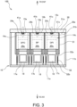
- the device main body 10 includes a housing 11, finger driving units 20 which are a plurality of tube pressing member driving units received inside the housing 11, a common pump tube opening/closing mechanism 50, and a common control unit 65.
- each of the finger driving units 20 (20a-20c) comprises a finger casing 14 (14a-14c) and a drive motor 17 (17a-17c).
- Each finger casing 14 (14a-14c) has a finger support portion 21 (21a-21c).
- the finger support portion 21 (21a-21c) supports fingers 15 (15a-15c), which are tube pressing members arranged in a plurality of rows in the vertical direction, in a front part of the finger casing 14 (14a-14c) in such a manner that the fingers 15 are movable in the front-rear direction of the device main body 10 while being housed inside the housing 11 of the device main body 10.
- a V-shaped tube receiving groove 24 (24a-24c) is formed extending vertically.
- the tube receiving grooves 24 may alternatively be not provided.
- plate-shaped guides extending in the vertical direction may be provided so as to prevent twisting of pump tubes 41a-41c (described further below).
- the respective drive motors 17 (17a-17c) drive the fingers 15 (15a-15c), which are the tube pressing members, in the front-rear direction of the device main body 10.
- the drive motors 17 are connected to the control unit 65 and are operated according to commands from the control unit 65.
- the housing 11 includes: a base 12; a rear plate 11a provided upright toward the rear end of the base 12; side plates 11b provided upright on both sides in the width direction of the base 12; a width plate 13b provided upright toward the front end of the base 12; a front plate 13c covering an upper part of the front side of the device main body 10; and a ceiling plate 13d.
- a plurality of ribs 13a extending in the front-rear direction are provided on the upper surface of the base 12.
- the pump tube opening/closing mechanism 50 includes: a casing guide 51 that supports the finger casings 14 (14a-14c) in a manner slidable in the front-rear direction; rotary cams 53 (53a-53c) that cause the finger driving units 20 (20a-20c) to advance toward the cover 30; coil springs 52 which are retraction springs constituting a retraction mechanism that causes the finger driving units 20 (20a-20c) to retract from the cover 30; and a motor 60 that rotates and drives the rotary cams 53 (53a-53c).
- the casing guide 51 includes a plurality of support plates 51a, guide bars 51b, and connecting members 51c.
- the support plates 51a are plate members extending in a longitudinal direction, which are attached to the upper ends of the plurality of ribs 13a provided on the upper surface of the base 12, and which support the bottom surfaces of the lower corners of the finger casings 14 (14a-14c).
- the guide bars 51b are plate members provided upright on the upper surfaces of the support plates 51a and extending in the longitudinal direction, which guide the side surfaces of the lower corners of the finger casings 14 (14a-14c) in the front-rear direction.
- the connecting members 51c are plate members that connect between the support plates 51a in the width direction. As shown in FIG.
- each of the support plates 51a located at the two widthwise ends supports the bottom surface of a lower corner of one finger casing 14 (14a or 14c), and each of the guide bars 51b provided upright on the upper surfaces of these support plates 51a located at the two widthwise ends guides a side surface of one finger casing 14 (14a or 14c) in the front-rear direction.
- each of the two central support plates 51a supports the bottom surfaces of lower corners of two adjacent finger casings 14 (14a-14c), and each of the guide bars 51b provided upright on the upper surfaces of these two central support plates 51a guides side surfaces of two adjacent finger casings 14 (14a-14c) in the front-rear direction.
- the casing guide 51 may be any member that guides the finger casings 14 (14a-14c) in the front-rear direction, and is not limited to the above-described configuration.
- pins 52a are attached, to each of which one end of the respective coil spring 52 is to be mounted.
- pins 52b are attached to the rear plate 11a of the device main body 10 at positions facing the respective pins 52a.
- the coil springs 52 are mounted between the pins 52a and the pins 52b.
- the finger casings 14 (14a-14c) and the rear plate 11a may alternatively be connected directly by the coil springs 52 without using the pins 52a and 52b.
- brackets 55 are attached, which rotatably support a shaft 61 to which the rotary cams 53 (53a-53c) are mounted.
- a pulley 56 is attached to one end of the shaft 61, while a collar 63 is attached to the other end.
- a bracket 58 is attached, and the motor 60 is fixed to the bracket 58.
- a pulley 59 is attached to a shaft 62 of the motor 60.
- the pulley 59 attached to the shaft 62 of the motor 60 and the pulley 56 attached to the shaft 61 to which the rotary cams 53 (53a-53c) are mounted are connected by a belt 57.
- the motor 60 is connected to the control unit 65 and is operated according to commands from the control unit 65.
- the motor 60, the pulleys 59 and 56, the belt 57, and the shaft 61 constitute a common cam driving unit that drives the plurality of rotary cams 53 (53a-53c).
- each finger casing 14 14a-14c
- two posts 54p are attached. Between the pairs of posts 54p, plate-shaped cam followers 54a-54c are mounted, which are abutted by the rotary cams 53 (53a-53c).
- the posts 54p and the cam followers 54a-54c may be not provided, and the rotary cams 53 may be configured to contact the rear surfaces of the finger casings 14 (14a-14c).
- the cover 30 is a flat plate member, and has the pump tubes 41a-41c mounted on its flat surface 30a located toward the device main body 10 (i.e., located toward the rear).
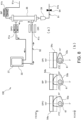
- the two ends of the pump tubes 41a-41c are connected to a blood circuit 91 and a dialysate circuit 92 shown in FIG. 6(a) .
- the surfaces of the pump tubes 41a-41c located toward the cover 30 are arranged along the flat surface 30a of the cover 30.
- the cover 30 constitutes a tube receiving plate that holds the pump tubes 41 (41a-41c).
- dialysate regeneration column 38 provided in the dialysate circuit 92 is omitted.
- the dialysate regeneration column 38 may be provided at any position in the dialysate circuit 92.
- the cover 30 When the cover 30 is closed, as shown in FIGs. 2 to 4 , the pump tubes 41 (41a-41c) are received in the tube receiving grooves 24 (24a-24c) of the finger casings 14 (14a-14c), and the finger driving units 20 (20a-20c) are arranged facing the cover 30 across the pump tubes 41 (41a-41c).
- the cover 30 need not be a flat plate member so long as the cover 30 has sufficient hardness for collapsing the pump tubes 41 (41a-41c) in cooperation with the fingers 15a-15c.
- the fingers 15 (15a-15c) are moved toward the cover 30, to thereby sandwich the pump tubes 41 (41a-41c) between the fingers 15 (15a-15c) and the cover 30, and to press the pump tubes 41 (41a-41c) against the surface 30a of the cover 30, so that the pump tubes 41 (41a-41c) become closed.
- the coil springs 52 are stretched out in the front-rear direction.
- the rotary cams 53 are moved away from the cam followers 54a-54c, the coil springs 52 pull the pins 52a back toward the rear plate 11a of the housing 11.
- the finger casings 14 (14a-14c) are moved toward the rear of the device main body 10 so as to move away from the cover 30, while being guided by the guide bars 51b of the casing guide 51.
- the fingers 15 (15a-15c) are moved in the direction away from the cover 30, and the fingers 15 (15a-15c) are moved out of contact with the surface of the pump tubes 41 (41a-41c), so that the pump tubes 41 (41a-41c) become opened.
- FIG. 6(b) shows the rotary cams 53a-53c mounted to the shaft 61.
- dash-dotted lines indicate the counterclockwise rotation angles of the shaft 61 and the rotary cams 53a-53c.
- the state shown in FIG. 6(b) is the initial position of the shaft 61 and the rotary cams 53a-53c.
- the rotary cams 53a and 53b have a small radius, and the cam followers 54a and 54b are placed in the rear open position.
- the rotary cams 53a and 53b have a large radius, and the cam followers 54a and 54b are placed in the front closed position as shown in FIG. 7(b) .
- the rotary cam 53c has a large radius, and the cam follower 54c is placed in the front closed position as shown in FIG. 7(b) .
- the rotary cam 53c When in the 0° and 180° rotation angle positions, the rotary cam 53c has a small radius, and the cam follower 54c is placed in the rear open position as shown in FIGs. 6(b) , 8(b) , and 9(b) .
- the rotary cams 53a-53c have shapes according to combinations of open and closed states of the pump tubes 41a-41c.
- the shaft 61 When the blood purification device 100 is in a stopped state, the shaft 61 is in the initial position in which, as shown in FIG. 6(b) , the 0° position is located facing the cam followers 54a-54c, and all of the cam followers 54a-54c are in the rear open position. In this state, the fingers 15a-15c of a dialysate outlet pump DPO, a blood pump BP, and a dialysate inlet pump DPI are located away from the respective pump tubes 41a-41c, as shown by dash-dotted lines in FIGs. 3 and 4 .
- the dialysate outlet pump DPO and the dialysate inlet pump DPI are to be driven to circulate dialysate to a dialyzer 36 and a water removal container 37 in the dialysate circuit 92.
- the blood pump BP is to be driven to cause blood from a human body to be delivered from a blood circuit inlet 91a to the dialyzer 36 and a drip chamber 39 in the blood circuit 91, and to be returned to the human body via a blood circuit outlet 91b.
- liquid delivering operation is to be carried out by the three pumps; namely, the dialysate outlet pump DPO, the dialysate inlet pump DPI, and the blood pump BP.
- the control unit 65 drives the motor 60 of the pump tube opening/closing mechanism 50 so as to rotate the shaft 61 by 90° from the initial position, to the position shown in FIG. 7(b) .
- the rotary cams 53a-53c are also rotated by 90° from the initial position, and all of the rotary cams 53a-53c push the cam followers 54a-54c forward into the front closed position.
- the finger casings 14a-14c are thereby moved forward.
- the pump tubes 41a, 41b, and 41c are placed in the closed state, and the dialysate outlet pump DPO, the blood pump BP, and the dialysate inlet pump DPI are placed in a state capable of delivering liquid.
- control unit 65 causes the drive motors 17a-17c of the finger driving units 20a-20c to rotate at a predetermined rotation speed.
- the fingers 15a-15c are sequentially moved in the direction of approaching and moving away from the cover 30, and a predetermined amount of liquid is delivered from the dialysate outlet pump DPO, the blood pump BP, and the dialysate inlet pump DPI. As shown in FIG.
- the dialysate outlet pump DPO and the dialysate inlet pump DPI cause the dialysate to circulate through the dialyzer 36 and the water removal container 37 in the dialysate circuit 92, while the blood pump BP causes the blood from the human body to be delivered from the blood circuit inlet 91a to the dialyzer 36 and the drip chamber 39 in the blood circuit 91 and to be returned to the human body via the blood circuit outlet 91b.
- priming is performed before the dialysis operation by, for example, circulating a physiological saline solution in the dialysate circuit 92 and the blood circuit 91.
- the dialysate circuit 92 as shown in FIG. 8(a) , the pump tube 41c of the dialysate inlet pump DPI is to be opened, and the priming solution is to be circulated to the dialysate circuit 92 using the dialysate outlet pump DPO.
- the control unit 65 drives the motor 60 of the pump tube opening/closing mechanism 50 so as to rotate the shaft 61 by 180° from the initial position to the position shown in FIG. 8(b) .
- the rotary cams 53a and 53b push the cam followers 54a and 54b forward to the closed position.
- the rotary cam 53c does not push the cam follower 54c forward, and the cam follower 54c that abuts the rotary cam 53c is in the rear open position.
- the finger casings 14a and 14b are moved forward, and the fingers 15a and 15b press the pump tubes 41a and 41b against the cover 30, so that the dialysate outlet pump DPO and the blood pump BP are placed in a state capable of delivering liquid.
- the finger casing 14c is not moved forward, so that the fingers 15c are located away from the pump tube 41c, and the pump tube 41c of the dialysate inlet pump DPI is in the open state.
- the blood circuit outlet 91b is closed by a valve 94 so that the priming solution is circulated in only the dialysate circuit 92.
- the control unit 65 rotates only the drive motor 17a of the finger driving unit 20a at a predetermined rotation speed.
- a predetermined amount of liquid is delivered from the dialysate outlet pump DPO.
- the dialysate outlet pump DPO causes the priming solution to be circulated through the dialyzer 36, the water removal container 37, and the pump tube 41c of the dialysate circuit 92.
- calibration of the liquid delivery amount of the blood pump BP may be performed.
- a calibration liquid bag 93 containing a physiological saline solution or the like is connected to the blood circuit inlet 91a of the blood circuit 91, and the blood circuit outlet 91b is closed by the valve 94, as shown in FIG. 9(a) .
- the pump tube 41a of the dialysate outlet pump DPO is to be closed while the pump tube 41c of the dialysate inlet pump DPI is opened, and the blood pump BP is to be driven so that the calibration liquid flows from the calibration liquid bag 93 through the dialyzer 36 and from the pump tube 41c of the dialysate inlet pump DPI to the water removal container 37.
- the weight of the water removal container 37 is detected by a weight detection unit 33 of the water removal container 37 so as to measure the liquid delivery amount of the blood pump BP. Based on this measurement, the liquid flow rate of the blood pump BP is to be calibrated.
- the control unit 65 drives the motor 60 of the pump tube opening/closing mechanism 50 so as to rotate the shaft 61 by 180° from the initial position to the position shown in FIG. 9(b) .
- the dialysate outlet pump DPO and the blood pump BP are placed in a state capable of delivering liquid, and the pump tube 41c of the dialysate inlet pump DPI is opened.
- the control unit 65 rotates the drive motor 17b of the finger driving unit 20b at a predetermined rotation speed, and a predetermined amount of liquid is thereby delivered from the blood pump BP, similar to the case of the above-described operation. Since the drive motor 17a is in the stopped state, the fingers 15a of the dialysate outlet pump DPO are in a state of closing the pump tube 41a. As shown in FIG. 9(a) , the blood pump BP delivers the calibration liquid from the calibration liquid bag 93 through the dialyzer 36, and from the pump tube 41c of the dialysate inlet pump DPI to the water removal container 37. Based on a drive command value transmitted to the blood pump BP and a delivered liquid weight detected by the weight detection unit 33 of the water removal container 37, calibration of the blood pump BP is carried out.
- the rotary cams 53a-53c have shapes corresponding to the combinations of open and closed states of the pump tubes 41a-41c necessary for the various operations of the blood purification device 100. Accordingly, by driving the single motor 60 of the pump tube opening/closing mechanism 50, the three finger casings 14 (14a-14c) can be caused to advance and retract with respect to the cover 30 so as to close and open the pump tubes 41 (41a-41c), and the dialysate circuit 92 and the blood circuit 91 can thereby be opened and closed in various patterns. In this way, in the blood purification device 100 including a plurality of pumps such as the dialysate outlet pump DPO, the dialysate inlet pump DPI, and the blood pump BP, various operations can be performed by a simple method.
- the dialysate outlet pump DPO the dialysate inlet pump DPI
- the blood pump BP various operations can be performed by a simple method.
- the pump tubes 41a-41c are reused.
- the term “reuse” means that consumables are not discarded after one blood purification treatment is completed, but are washed and disinfected as necessary and then used again for the next treatment.
- the pump tubes 41a-41c are reused, the liquid delivery amount may become changed due to degradation caused by use.
- calibration of the blood pump BP can be performed by driving the motor 60 of the pump tube opening/closing mechanism 50 to thereby close the pump tubes 41a and 41b and to place the pump tube 41c in the open state, and delivering a predetermined amount of liquid from the blood pump BP. Accordingly, even when the pump tube 41b is degraded by reuse, the blood pump BP can be easily calibrated to correct the flow rate.
- the pump tubes 41a-41c can be opened and prevented from being subjected to a pressing force while in the stopped state. It is thereby possible to suppress degradation of the pump tubes 41a-41c due to use.
- the opening and closing of the pump tubes 41 (41a-41c) are carried out by causing the finger driving units 20 (20a-20c) housed in the device main body 10 to advance and retract with respect to the cover 30 by means of the pump tube opening/closing mechanism 50 housed in the device main body 10. Accordingly, even when the pump tubes 41 (41a-41c) are arranged in the cover 30 where it is difficult to mount a mechanism for moving the pump tubes 41 (41a-41c), opening and closing of the liquid circuit can be carried out with a simple configuration.
- the rotary cams 53a-53c are described as having shapes that can set the open and closed states of the pump tubes 41a-41c corresponding to the stopped state, the dialysis operation, the priming operation, and the blood pump BP calibration operation of the blood purification device 100.
- the shapes of the rotary cams 53a-53c are not limited thereto, and may also be those that correspond to combinations of open and closed states of the pump tubes 41a-41c required for other operations.
- rotation angle positions are assigned at intervals of 90° as in the case of the rotary cams 53a-53c described above, six patterns of rotary cams as shown in FIGs. 10(a) to 10(f) can be obtained.
- the rotary cam shown in FIG. 10(a) has a pattern for opening a pump tube 41 at all angular positions.
- the rotary cam shown in FIG. 10(b) has a pattern for closing a pump tube 41 at the 90° position and opening the pump tube 41 at the 0°, 180°, and 270° positions, similar to the rotary cam 53c described above.
- the rotary cam shown in FIG. 10(c) has a pattern for closing a pump tube 41 at the 90° position and the 180° position and opening the pump tube 41 at the 0° position and the 270° position, similar to the rotary cams 53a and 53b described above.
- the rotary cam shown in FIG. 10(e) has a pattern for closing a pump tube 41 at the 90°, 180°, and 270° positions and opening the pump tube 41 at the 0° position.
- the rotary cam shown in FIG. 10(f) has a pattern for closing a pump tube 41 at all angular positions.
- the blood purification device 100 can be operated in various operation patterns by driving the single motor 60 of the pump tube opening/closing mechanism 50.
- the assignment interval angle is not limited to 90°, and may alternatively be 45° or 60°, for example.
- a short side of the rotary cam corresponds to an open state and a long side corresponds to a closed state
- FIGs. 11 to 13 Parts equivalent to those of the blood purification device 100 described above by reference to FIGs. 1 to 9 are labeled with the same reference signs, and repeated description thereof will be omitted.
- a single rotary cam 75 that is rotated within a horizontal plane by a shaft 79 is used, instead of the three rotary cams 53a-53c of the blood purification device 100, to thereby cause the finger casings 14a-14c to advance and retract with respect to the cover 30.
- projections 71a-71c that come into contact with the cam surfaces of the rotary cam 75 are provided respectively on the cam followers 54a-54c.
- the projections 71a-71c are connected to the finger casings 14a-41c via the cam followers 54a-54c and the posts 54p.
- the rotary cam 75 includes: a first cam surface 76 that places the projections 71a-71c connected to the finger casings 14a-41c in the rear open position as shown in FIG. 11 ; a second cam surface 77 that places the projections 71a-71c in the front closed position as shown in FIG. 12 ; and a third cam surface 78 that places the projections 71a and 71b in the front closed position and places the projection 71c in the rear open position as shown in FIG. 13 .
- the first cam surface 76 is the 0° position
- the second cam surface 77 is the 90° position
- the third cam surface 78 is the 180° position.
- the blood purification device 200 of the present embodiment achieves the same advantageous effects as the blood purification device 100 described above.
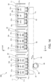
- FIG. 14 depicts, in a sequential manner, respective states in which first to third cam surfaces 81, 82, and 83 of a plate cam 80 are located in a central part of the housing 11.
- first cam surface 81 when the first cam surface 81 is inside the housing 11, the second cam surface 82 and the third cam surface 83 are located outside the housing 11.
- second cam surface 82 when the first cam surface 81 is inside the housing 11, the first cam surface 81 and the third cam surface 83 are located outside the housing 11.
- the third cam surface 83 is inside the housing 11, the first cam surface 81 and the second cam surface 82 are located outside the housing 11.
- the blood purification device 300 of the present embodiment is configured by replacing the rotary cam 75 of the blood purification device 200 described above by reference to FIGs. 11 to 13 with the linearly-extending plate cam 80. As shown in FIG. 14 , the plate cam 80 is moved to the left and the right by rotation of a drive gear 85 in engagement with a gear surface 84.
- the plate cam 80 comprises: the first cam surface 81 that places the projections 71a-71c in the rear open position; the second cam surface 82 that places the projections 71a-71c in the front closed position as shown in FIG. 12 ; and the third cam surface 83 that places the projections 71a and 71b in the front closed position and places the projection 71c in the rear open position as shown in FIG. 13 .
- the blood purification device 300 of the present embodiment achieves the same advantageous effects as the blood purification devices 100 and 200 described above.
- the blood purification device 400 of the present embodiment is configured such that a cassette 130 having a rear plate 32 is detachably mounted thereto, instead of the cover 30 of the blood purification device 100 described by reference to FIGs. 1 to 9 .
- Parts equivalent to those of the blood purification device 100 described above by reference to FIGs. 1 to 9 are labeled with the same reference signs, and repeated description thereof will be omitted.
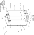
- the blood purification device 400 comprises the device main body 10, and the cassette 130 that is detachably mounted to the device main body 10.
- the cassette 130 is mounted to the device main body 10 by fitting its lower part into a cassette receiving seat 96 of the device main body 10, and fastening a hook 35 provided on its upper part with a metal fixture 95 provided on the device main body 10.
- a blood circuit inlet 91a and a blood circuit outlet 91b of the cassette 130 are respectively connected to blood vessels of a human body so as to carry out dialysis.
- the direction in which the device main body 10 and the cassette 130 are arranged will be referred to as the front-rear direction
- the direction orthogonal to the front-rear direction in a horizontal plane will be referred to as the width direction
- the upright direction will be referred to as the vertical direction.
- a casing 31 of the cassette 130 houses therein the dialyzer 36, the dialysate regeneration column 38, and the water removal container 37.
- the plurality of elastic pump tubes 41 (41a-41c) are mounted on a surface 32a of the rear plate 32, which is a flat plate of the casing 31 that is located facing the device main body 10. Accordingly, similar to the cover 30 described above, the rear plate 32 of the cassette 130 of the present embodiment constitutes a tube receiving plate that holds the pump tubes 41 (41a-41c).
- the device main body 10 includes the housing 11, finger driving units 20 received inside the housing 11, the pump tube opening/closing mechanism 50, and the control unit 65.
- the finger driving units 20, the pump tube opening/closing mechanism 50, and the control unit 65 are identical to those of the blood purification device 100 described above.
- the base 12 of the housing 11 extends forward, and the cassette receiving seat 96 is mounted to the extended portion.
- the cassette receiving seat 96 is formed by providing a flange 96b, into which the cassette 130 is to be fitted, in an upright manner in a cornered C-shape on a peripheral portion of a bottom plate 96a.
- the pump tubes 41 (41a-41c) are received in the vertically-extending V-shaped tube receiving grooves 24 (24a-24c) provided on the front surfaces of the finger casings 14 (14a-14c), in the same manner as described above by reference to FIGs. 3 and 4 .
- the finger driving units 20a-20c and the pump tubes 41a-41c constitute the dialysate outlet pump DPO, the blood pump BP, and the dialysate inlet pump DPI, respectively.
- the dialyzer 36, the water removal container 37, the dialysate regeneration column 38, the pump tubes 41a-41c, and connection tubes connecting between the respective components, all of which constitute the blood circuit 91 and the dialysate circuit 92, are housed in the cassette 130 as a single unit, and this unit can be mounted to and detached from the device main body 10.
- the blood purification device 400 of the present embodiment also achieves the advantageous effects that the cassette 130 integrating the liquid-contacting section can be used in a disposable manner and that the handling of the blood purification device 400 can thereby be simplified.
- the blood purification device 500 of the present embodiment is such that, in addition to the cam followers 54a-54c arranged toward the front of the rotary cams 53a-53c, cam followers 54d-54f are provided toward the rear, and the cam followers 54a-54c are respectively formed into single units with the cam followers 54d-54f by being connected by connecting members 54g.
- the configurations of the rotary cams 53a-53c and the cam followers 54a-54c are identical to those of the blood purification device 100 described above by reference to FIGs. 1 to 9 .
- the blood purification device 500 does not include the coil springs 52.
- the rotary cams 53a-53c, the cam followers 54a-54c and 54d-54f, and the connecting members 54g constitute the retraction mechanism.
- the finger casings 14a-14b are moved in the front-rear direction by engaging the two front and rear cam followers 54a-54c and 54d-54f with the respective rotary cams 53a-53b, without using the coil springs 52.
- the blood purification device 500 of the present embodiment achieves the same advantageous effects as the blood purification device 100 described above.
- the blood purification device 600 of the present embodiment is configured by providing a flat-shaped tube receiving plate 140 between the cover 30 and the pump tubes 41 (41a-41c). By rotating rotary cams 53d attached to the shaft 61, the tube receiving plate 140 is caused to advance toward the finger driving units 20 (20a-20c). Further, the tube receiving plate 140 is pulled back toward the cover 30 by coil springs 152 so as to be retracted from the finger driving units 20 (20a-20c). In the blood purification device 600, the finger driving units 20 (20a-20c) are fixed to the device main body 10, and do not move in the front-rear direction.
- the tube receiving plate 140 is a flat-shaped member disposed between the cover 30 and the pump tubes 41 (41a-41c), and has sufficient hardness for collapsing the pump tubes 41 (41a-41c) in cooperation with the fingers 15a-15c.
- the vertical length of the tube receiving plate 140 is the same as the vertical length of the fingers 15a-15c.
- the tube receiving plate 140 is held on the cover 30 together with the pump tubes 41 (41a-41c).
- flanges 141 are provided extending rearward.
- connection mechanisms 142 are attached, which, when the cover 30 is closed, engage with cam arms 143 mounted to the housing 11.
- a rib 145 protrudes from a side surface of each flange 141, and the coil spring 152 is attached between the rib 145 and the cover 30.
- each rotary cam 53d has at least one protruded part, and may have, for example, the same shape as the rotary cam 53a or the rotary cam 53c shown in FIG. 6(b) .
- the tube pressing members are the fingers 15 (15a-15c) in the blood purification devices 100, 200, 300, 400, 500, and 600 of the above-described embodiments
- the tube pressing members are not limited thereto, and may alternatively be rollers that squeeze the pump tubes 41 (41a-41c).
- the surface 30a of the cover 30 located toward the device main body 10 and the surface of the tube receiving plate 140 located toward the device main body 10 are configured as a curved surface that conforms to the shape of the outer surface of the rollers.
- FIGs. 19-24 Parts equivalent to those of the blood purification device 100 described above by reference to FIGs. 1-9 are labeled with the same reference signs, and repeated description thereof will be omitted.
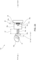
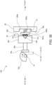
- the blood purification device 110 is configured by attaching the cam followers 54a-54c to the finger casings 14 (14a-14c) of the finger driving units 20 (20a-20c) via adjustment springs 54s, which are elastic members.
- adjustment springs 54s which are elastic members.
- Other structures are identical to those of the blood purification device 100 described above by reference to FIGs. 1 to 9 .
- a post 54p is fixed to a front part of the cam follower 54a, and a recess 23 into which the tip of the post 54p is inserted is formed in the back plate 22 of the finger casing 14a. Further, a washer 54q having an inner diameter substantially equal to the diameter of the post 54p is fixed to the peripheral edge of the recess 23 in the back plate 22.
- An adjustment spring 54s is mounted to the outer periphery of the post 54p between the washer 54q and the cam follower 54a.
- the adjustment spring 54s is a coil spring in the blood purification device 110, the adjustment spring 54s is not limited thereto, and may alternatively be a leaf spring or may comprise a rubber member.
- the washer 54q may alternatively be not provided.
- the rotary cam 53a is rotated so as to cause the cam follower 54a to advance toward the finger driving unit 20a.
- the adjustment spring 54s is thereby contracted, the tip of the post 54p enters into the recess 23 in the back plate 22.
- the spring constant of the adjustment spring 54s is greater than the spring constant in the direction in which the pump tubes 41 (41a-41c) are collapsed, is equal to or greater than a spring constant at which the pump tubes 41 (41a-41c) can be completely closed by the reaction force, and is such that, even when the spring 54s is compressed, the reaction force does not damage the pump tubes 41 (41a-41c).
- FIGs. 22-24 are schematic diagrams for explaining the closing operation, and elements shown therein are depicted in a simplified manner.
- the operation of the finger driving units 20b and 20c is identical to the operation of the finger driving unit 20a.
- the adjustment spring 54s has a reference length L1
- the outer shape of the pump tube 41a has a size d1.
- the cam follower 54a advances toward the cover 30.
- the spring constant of the adjustment spring 54s is greater than the spring constant in the direction in which the pump tube 41a is collapsed. Accordingly, when the cam follower 54a advances toward the cover 30, the pump tube 41a becomes collapsed by being squeezed between the finger 15a and the cover 30.
- the pump tube 41a has a thickness d2. At that point, the cam follower 54a has advanced by (d1-d2) + (L1-L2), and the adjustment spring 54s has a length L2 that is slightly reduced from the reference length L1.
- the adjustment spring 54s contracts by a length (L2-L3) and thereby absorbs an advancing distance of the cam follower 54a. For this reason, closing and opening of the pump tube 41a can be carried out reliably without adjustment of the advancing distance of the finger driving unit 20a with respect to the cover 30 with high accuracy.
- the reaction force of the adjustment spring 54s upon contracting to the length L3 is of a magnitude that does not damage the pump tube 41a, excessive pressing of the pump tube 41a can be avoided, and damages to the pump tube 41a can be suppressed.
- the recess 23 into which the tip of the post 54p is inserted is provided in the back plate 22 of the finger casing 14a
- the recess 23 may be not provided so long as the structure is such that the tip of the post 54p does not interfere with the back plate 22 when the adjustment spring 54s is in the contracted state.
- it may be configured such that the thickness of the washer 54q is greater than the extent of contraction of the adjustment spring 54s, so that the tip of the post 54p advances into the washer 54q when the adjustment spring 54s contracts.
- the portion of the back plate 22 abutted by the adjustment spring 54s may be formed in a protruded shape.
- a blood purification device 112 which is a variant of the blood purification device 110, will be described by reference to FIG. 25 .
- the blood purification device 112 is configured such that, in a state where the finger 15a has moved to the frontmost position, the front end of the finger 15a is located rearward by a distance d2 from the front end 25a of the finger driving unit 20a.
- the configuration of the finger driving units 20b and 20c is the same as that of the finger driving unit 20a.
- Other structures are identical to those of the blood purification device 110 described above with reference to FIGs. 19-24 .
- a blood purification device 115 which is a variant of the blood purification device 110, will be described by reference to FIG. 26 .
- the post 54p is fixed to the back plate 22 of the finger casing 14a, and the cam follower 54a has formed therein a through hole 54Ha which is penetrated by the post 54p.
- the adjustment spring 54s is mounted around the post 54p between the back plate 22 and the cam follower 54a.
- the rotary cam 53 pushes the cam follower 54a forward and the adjustment spring 54s contracts, the rear end of the post 54p advances rearward through the through hole 54Ha in the cam follower 54a.
- the configurations of the back plates 22 of the finger casings 14b and 14c, the cam followers 54b and 54c, and the posts 54p are the same as those described above.
- the blood purification device 115 is identical in operation to that of the blood purification device 110 described above, and achieves the same advantageous effects.
- FIGs. 27-31 Parts equivalent to those of the blood purification device 100 described above by reference to FIGs. 1-9 are labeled with the same reference signs, and repeated description thereof will be omitted.
- recesses 30Aa-30Ac are formed at portions of the cover 30 facing the fingers 15a-15c of the finger driving units 20a-20c, and inside the recesses 30Aa-30Ac, tube support plates 30Ba-30Bc, which are the tube receiving plates, are mounted via adjustment springs 30Sa-30Sc.
- the pump tube opening/closing mechanism 50 causes the rotary cams 53a-53c to rotate and thereby causes the finger driving units 20a-20c to advance and retract with respect to the tube support plates 30Ba-30Bc, so as to carry out closing and opening of the pump tubes 41a-41c respectively disposed between the fingers 15a-15c of the finger driving units 20a-20c and the tube support plates 30Ba-30Bc.
- Other structures are identical to those of the blood purification device 100 described above by reference to FIGs. 1-9 . So long as the tube support plates 30Ba-30Bc are attached to the cover 30 via the adjustment springs 30Sa-30Sc, it is possible that the configuration includes no recesses 30Aa-30Ac. Further, the portions of the cover 30 abutted by the adjustment springs 30Sa-30Sc may be formed in a protruded shape.
- the spring constants of the adjustment springs 30Sa-30Sc are greater than the spring constant in the direction in which the pump tubes 41 (41a-41c) are collapsed, are equal to or greater than a spring constant at which the pump tubes 41 (41a-41c) can be completely closed by the reaction force, and are such that, even when the adjustment springs 30Sa-30Sc are compressed, the reaction force does not damage the pump tubes 41 (41a-41c).
- FIGs. 29-31 are schematic diagrams for explaining the closing operation, and elements shown therein are depicted in a simplified manner.
- the operation of the finger driving units 20b and 20c is identical to the operation of the finger driving unit 20a.
- the adjustment spring 30Sa has a reference length L4, and the outer shape of the pump tube 41a has a size d1.
- the cam follower 54a advances toward the cover 30.
- the spring constant of the adjustment spring 30Sa is greater than the spring constant in the direction of squeezing the pump tube 41a. Accordingly, when the cam follower 54a advances toward the cover 30, the pump tube 41a becomes collapsed by being squeezed between the finger 15a and the tube support plate 30Ba.
- the pump tube 41a has a thickness d2. At that point, the cam follower 54a has advanced by (d1-d2) + (L4-L5), and the adjustment spring 30Sa has a length L5 that is slightly reduced from the reference length L4.
- the adjustment spring 30Sa contracts by a length (L5-L6) and thereby absorbs an advancing distance of the cam follower 54a. For this reason, closing and opening of the pump tube 41a can be carried out reliably without adjustment of the advancing distance of the finger driving unit 20a with respect to the cover 30 with high accuracy.
- the reaction force of the adjustment spring 30Sa upon contracting to the length L6 is of a magnitude that does not damage the pump tube 41a, excessive pressing of the pump tube 41a can be avoided, and damages to the pump tube 41a can be suppressed.
- the adjustment spring 30Sa is a coil spring in the blood purification device 120, the adjustment spring 30Sa is not limited thereto, and may alternatively be a leaf spring or may comprise a rubber member.
- a blood purification device 122 which is a variant of the blood purification device 120, will be described by reference to FIG. 32 .
- the blood purification device 122 is configured such that, in a state where the finger 15a has moved to the frontmost position, the front end of the finger 15a is located rearward by a distance d2 from the front end 25a of the finger driving unit 20a.
- the configuration of the finger driving units 20b and 20c is the same as that of the finger driving unit 20a.
- Other structures are identical to those of the blood purification device 120 described above with reference to FIGs. 27-31 .
- the spring constant of the adjustment spring 30Sa is adjusted such that, at that point, a gap e is present between the front end 25a of the finger driving unit 20a and the surface 30a of the cover 30.
- adjustment springs 54s are respectively provided between the finger driving units 20a-20c and the cam followers 54a-54c in the blood purification devices 110 and 112, and that the adjustment springs 30Sa-30Sc are provided between the finger driving units 20a-20c and the cover 30 in the blood purification devices 120 and 122, embodiments are not limited thereto.
- an embodiment may be configured such that the adjustment springs 54s are respectively provided between the finger driving units 20a-20c and the cam followers 54a-54c, and in addition, the adjustment springs 30Sa-30Sc are provided between the finger driving units 20a-20c and the cover 30.
- an embodiment may be configured such that, for a part of the finger driving units 20a-20c, the adjustment springs 54s are respectively disposed between those finger driving units and the cam followers 54a-54c, and for another part of the finger driving units 20a-20c, the adjustment springs 30Sa are disposed between those finger driving units and the cover 30.
- tips of the cam arms 143 are each formed in an L-shape to thereby provide tip portions 143A that face the rotary cams 53d. Respectively between the tip portions 143A and the rotary cams 53d, cam followers 155 are arranged via adjustment springs 154s, which are elastic members. Further, adjustment springs 143s are provided between the cam arms 143 and the connection mechanisms 142. Other structures are identical to those of the blood purification device 600 described by reference to FIG. 18 .
- a post 154p is fixed to a rear part of each cam follower 155, and a recess 143B into which the tip of the post 154p is inserted is formed in the tip portion 143A. Further, a washer 154q having an inner diameter substantially equal to the diameter of the post 154p is fixed to the peripheral edge of the recess 143B in the tip portion 143A.
- the adjustment spring 154s is mounted to the outer periphery of the post 154p between the washer 154q and the cam follower 155.
- the adjustment spring 154s is a coil spring in the blood purification device 610, the adjustment spring 154s is not limited thereto, and may alternatively be a leaf spring or may comprise a rubber member.
- the rotary cam 53a is rotated so as to cause the cam follower 154a to advance toward the tip portion 143A.
- the adjustment spring 154s is thereby contracted, the tip of the post 154p advances into the recess 143B in the tip portion 143A.
- the adjustment springs 154s and 143s contract and thereby absorb an advancing distance of the cam followers 155. Accordingly, closing and opening of the pump tubes 41a-41c can be carried out reliably without adjustment of the advancing distance of the cam arms 143 with high accuracy, and at the same time, damages to the pump tube 41a-41c can be suppressed.
- the adjustment springs 154s and 143s are respectively provided between the tip portions 143A of the cam arms 143 and the rotary cams 53d and between the cam arms 143 and the connection mechanisms 142
- embodiments are not limited thereto.
- An embodiment may be configured such that the adjustment springs are provided at only either one of the above-noted sites.
- the posts 154p are attached to the tip portions 143A without providing the recesses 143B, and through holes to be penetrated by the posts 154p are formed in the cam followers 155.
Landscapes
- Health & Medical Sciences (AREA)
- Heart & Thoracic Surgery (AREA)
- Engineering & Computer Science (AREA)
- Veterinary Medicine (AREA)
- General Health & Medical Sciences (AREA)
- Anesthesiology (AREA)
- Biomedical Technology (AREA)
- Hematology (AREA)
- Life Sciences & Earth Sciences (AREA)
- Animal Behavior & Ethology (AREA)
- Cardiology (AREA)
- Public Health (AREA)
- Vascular Medicine (AREA)
- Mechanical Engineering (AREA)
- Urology & Nephrology (AREA)
- Emergency Medicine (AREA)
- Pulmonology (AREA)
- External Artificial Organs (AREA)
Claims (13)
- Dispositif de purification de sang (100, 110, 112, 115, 120, 122, 200, 300, 400, 500, 600, 610), comprenant :une plaque de réception de tube (140), laquelle maintient un tube de pompe élastique (41, 41a-41c) ;une unité d'entraînement d'élément de pressage de tube (20, 20a-20c), laquelle est positionnée en face de la plaque de réception de tube (140) à travers le tube de pompe élastique (41, 41a-41c), et laquelle fait en sorte que l'élément de pressage de tube (15, 15a-15c) soit déplacé par rapport à la plaque de réception de tube (140), etun mécanisme d'ouverture/fermeture de tube de pompe (50), lequel fait en sorte que l'unité d'entraînement d'élément de pressage de tube (20, 20a-20c) avance ou se rétracte par rapport à la plaque de réception de tube (140), et réalise ainsi la fermeture et l'ouverture du tube de pompe (41, 41a-41c), lequel est positionné entre l'élément de pressage de tube (15, 15a-15c) et la plaque de réception de tube (140).
- Dispositif de purification de sang (100, 110, 112, 115, 120, 122, 200, 300, 400, 500, 600, 610) selon la revendication 1, dans lequel
le mécanisme d'ouverture/fermeture de tube de pompe (50) comprend une came (53, 53a-53d, 75), laquelle fait en sorte que l'unité d'entraînement d'élément de pressage de tube (20, 20a-20c) avance vers la plaque de réception de tube (140), et un mécanisme de rétraction, lequel fait en sorte que l'unité d'entraînement d'élément de pressage de tube (20, 20a-20c) se rétracte à partir de la plaque de réception de tube (140). - Dispositif de purification de sang (100, 110, 112, 115, 120, 122, 200, 300, 400, 500, 600, 610) selon la revendication 2, dans lequella plaque de réception de tube (140) maintient une pluralité de tubes de pompe (41, 41a-41c), chacun étant ledit tube de pompe (41, 41a-41c) ;l'unité d'entraînement d'élément de pressage de tube (20, 20a-20c) est prévue sous la forme d'une pluralité ;le mécanisme d'ouverture/fermeture de tube de pompe (50) comprend : une pluralité de cames (53, 53a-53d), chacune étant ladite came (53, 53a-53d), laquelle fait en sorte que la pluralité d'unités d'entraînement d'élément de pressage de tube (20, 20a-20c) avancent vers la plaque de réception de tube (140) ; une unité d'entraînement de came commune, laquelle fait tourner et entraîne la pluralité de cames (53, 53a-53d), et une pluralité de mécanismes de rétraction, lesquels font en sorte que la pluralité d'unités d'entraînement d'élément de pressage de tube (20, 20a-20c) se rétractent de la plaque de réception de tube (140), etle mécanisme d'ouverture/fermeture de tube de pompe (50) fait en sorte que l'unité d'entraînement de came (20, 20a-20c) entraîne la pluralité de cames (53, 53a-53d), de sorte que la pluralité d'unités d'entraînement d'élément de pressage de tube (20, 20a-20c) font en sorte d'avancer et de se rétracter par rapport à la plaque de réception de plaque (140), et réalise ainsi l'ouverture et la fermeture de la pluralité de tubes de pompe (41, 41a-41c), lesquels sont positionnés entre une pluralité d'éléments de pressage de tube (15, 15a-15c), chacun étant ledit élément de pressage de tube (15, 15a-15c) de la pluralité d'unités d'entraînement d'élément de pressage de tube (20, 20a-20c), et la plaque de réception de tube (140).
- Dispositif de purification de sang (100, 110, 112, 115, 120, 122, 200, 300, 400, 500, 600, 610) selon la revendication 3, dans lequel
la pluralité de cames (53, 53a-53d) présente des formes correspondant à des combinaisons d'états ouverts et fermés de la pluralité de tubes de pompe (41, 41a-41c). - Dispositif de purification de sang (100, 110, 112, 115, 120, 122, 200, 300, 400, 500, 600, 610) selon l'une quelconque des revendications 1 à 4, comprenant en outre :un corps principal de dispositif (10) à l'intérieur duquel sont agencés l'unité d'entraînement d'élément de pressage de tube (20, 20a-20c) et le mécanisme d'ouverture/fermeture de tube de pompe (50), dans lequella plaque de réception de tube (140) est une plaque située de manière à faire face au corps principal de dispositif (10).
- Dispositif de purification de sang (100, 110, 112, 115, 120, 122, 200, 300, 400, 500, 600, 610) selon la revendication 5, comprenant en outre :une cassette (130), laquelle est montée de manière amovible sur le corps principal de dispositif (10), dans lequella cassette (130) inclut un boîtier (31), lequel contient un dialyseur (36), une colonne de régénération de dialysat (38), et un récipient de retrait d'eau (37), etla plaque de réception de tube (140) est une plaque du boîtier (31), laquelle est située en face du corps principal de dispositif (10).
- Dispositif de purification de sang (100, 110, 112, 115, 120, 122, 200, 300, 400, 500, 600, 610) selon la revendication 1, dans lequelle mécanisme d'ouverture/fermeture de tube de pompe (50) inclut une came (53, 53a-53d, 75), laquelle fait en sorte que la plaque de réception de tube (140) avance vers l'unité d'entraînement d'élément de pressage de tube (20, 20a-20c), et un mécanisme de rétraction, lequel fait en sorte que la plaque de réception de tube (140) se rétracte de l'unité d'entraînement d'élément de pressage de tube (20, 20a-20c),la plaque de réception de tube (140) maintient une pluralité de tubes de pompe (41, 41a-41c), chacun étant ledit tube de pompe (41, 41a-41c) ;l'unité d'entraînement d'élément de pressage de tube (20, 20a-20c) est prévue sous la forme d'une pluralité ;la came (53, 53a-53d, 75) du mécanisme d'ouverture/fermeture de tube de pompe (50) fait en sorte que la plaque de réception de tube (140) avance vers la pluralité d'unités d'entraînement d'élément de pressage de tube (20, 20a-20c), et réalise ainsi la fermeture et l'ouverture de la pluralité de tubes de pompe (41, 41a-41c), lesquels sont positionnés entre une pluralité d'éléments de pressage de tube (15, 15a-15c), chacun étant ledit élément de pressage de tube (15, 15a-15c), de la pluralité d'unités d'entraînement d'élément de pressage de tube (20, 20a-20c) et la plaque de réception de tube (140).
- Dispositif de purification de sang (100, 110, 112, 115, 120, 122, 200, 300, 400, 500, 600, 610) selon l'une quelconque des revendications 2, 3, 4 et 7, dans lequel le mécanisme de rétraction est un ressort de rétraction (52).
- Dispositif de purification de sang (100, 110, 112, 115, 120, 122, 200, 300, 400, 500, 600, 610) selon l'une quelconque des revendications 1 à 8, dans lequel
l'élément de pressage de tube (15, 15a-15c) est composé d'une pluralité de doigts (15, 15a-15c). - Dispositif de purification de sang (100, 110, 112, 115, 120,122, 200, 300, 400, 500, 600, 610) selon la revendication 1, dans lequel le mécanisme d'ouverture/fermeture de tube de pompe (50) comprend :une came (53, 53a-53d, 75), laquelle fait en sorte que l'unité d'entraînement d'élément de pressage de tube (20, 20a-20c) avance vers la plaque de réception de tube (140) via un galet de came (155), lequel est fixé sur l'unité d'entraînement d'élément de pressage de tube (20, 20a-20c) via un élément élastique (54s), etun mécanisme de rétraction, lequel fait en sorte que l'unité d'entraînement d'élément de pressage de tube (20, 20a-20c) se rétracte de la plaque de réception de tube (140).
- Dispositif de purification de sang (100, 110, 112, 115, 120, 122, 200, 300, 400, 500, 600, 610) selon la revendication 2 ou 10, comprenant en outre :un corps principal de dispositif (10) à l'intérieur duquel sont agencés l'unité d'entraînement d'élément de pressage de tube (20, 20a-20c) et le mécanisme d'ouverture/fermeture de tube de pompe (50), etun couvercle (30) fixé de manière à faire face au corps principal de dispositif (10), dans lequella plaque de réception de tube (140) est fixée sur le couvercle (30) via un autre élément élastique.
- Dispositif de purification de sang (100, 110, 112, 115, 120, 122, 200, 300, 400, 500, 600, 610) selon la revendication 7, dans lequel le mécanisme d'ouverture/fermeture de tube de pompe (50) inclut :un bras de came (143) relié à la plaque de réception de tube (140), etun galet de came (154, 155) fixé au bras de came (143) via un élément élastique,dans lequella came (53, 53a-53a, 75) fait en sorte que la plaque de réception de tube (140) reliée au bras de came (143) avance vers l'unité d'entraînement d'élément de pressage de tube (20, 20a-20c) via le galet de came (154, 155).
- Dispositif de purification de sang (100, 110, 112, 115, 120, 122, 200, 300, 400, 500, 600, 610) selon la revendication 7 ou 12, dans lequel
la plaque de réception de tube (140) et le bras de came (143) sont reliés via un autre élément élastique.
Applications Claiming Priority (2)
| Application Number | Priority Date | Filing Date | Title |
|---|---|---|---|
| JP2018158106 | 2018-08-27 | ||
| PCT/JP2019/033423 WO2020045384A1 (fr) | 2018-08-27 | 2019-08-27 | Dispositif de purification du sang |
Publications (3)
| Publication Number | Publication Date |
|---|---|
| EP3845256A1 EP3845256A1 (fr) | 2021-07-07 |
| EP3845256A4 EP3845256A4 (fr) | 2022-06-08 |
| EP3845256B1 true EP3845256B1 (fr) | 2025-01-15 |
Family
ID=69643022
Family Applications (1)
| Application Number | Title | Priority Date | Filing Date |
|---|---|---|---|
| EP19855616.9A Active EP3845256B1 (fr) | 2018-08-27 | 2019-08-27 | Dispositif de purification du sang |
Country Status (5)
| Country | Link |
|---|---|
| US (1) | US12053564B2 (fr) |
| EP (1) | EP3845256B1 (fr) |
| JP (1) | JP7300453B2 (fr) |
| CN (1) | CN112601561B (fr) |
| WO (1) | WO2020045384A1 (fr) |
Family Cites Families (23)
| Publication number | Priority date | Publication date | Assignee | Title |
|---|---|---|---|---|
| US4286728A (en) | 1980-04-11 | 1981-09-01 | Ermal C. Fraze | Tab and ecology end |
| DE3302804C2 (de) * | 1983-01-28 | 1985-03-14 | Fresenius AG, 6380 Bad Homburg | Vorrichtung zur Entfernung von Wasser aus Blut |
| CA1296591C (fr) * | 1986-12-03 | 1992-03-03 | Meddiss, Inc. | Generateur d'ecoulement pulsatoire |
| US5211548A (en) * | 1989-07-31 | 1993-05-18 | Terumo Kabushiki Kaisha | Peristaltic pump having a motor overload protector |
| US5062775A (en) | 1989-09-29 | 1991-11-05 | Rocky Mountain Research, Inc. | Roller pump in an extra corporeal support system |
| GB2273533B (en) * | 1992-12-18 | 1996-09-25 | Minnesota Mining & Mfg | Pumping cassette with integral manifold |
| JP3290263B2 (ja) * | 1993-08-30 | 2002-06-10 | テルモ株式会社 | 蠕動型輸液ポンプの駆動制御方法 |
| JP2000107281A (ja) | 1998-10-05 | 2000-04-18 | Terumo Corp | ローラポンプおよび血液処理回路 |
| JP3900355B2 (ja) * | 2003-09-29 | 2007-04-04 | 日本サーボ株式会社 | チューブポンプ |
| US8834399B2 (en) * | 2010-12-07 | 2014-09-16 | Zoll Lifebridge Gmbh | Cardiopulmonary apparatus and methods for preserving organ viability |
| JP2007296134A (ja) * | 2006-04-28 | 2007-11-15 | Terumo Corp | 送液装置およびその送液方法 |
| JP2008178444A (ja) * | 2007-01-23 | 2008-08-07 | Ube Junken:Kk | ローラポンプ |
| WO2010093946A1 (fr) * | 2009-02-12 | 2010-08-19 | Mc3, Inc. | Pompe modulaire dotée d'une cartouche |
| US9677555B2 (en) | 2011-12-21 | 2017-06-13 | Deka Products Limited Partnership | System, method, and apparatus for infusing fluid |
| CN104507516B (zh) * | 2012-05-24 | 2018-02-16 | 德卡产品有限公司 | 用于输注流体的装置 |
| JP5934581B2 (ja) * | 2012-06-04 | 2016-06-15 | 東レ・メディカル株式会社 | 血液浄化装置 |
| JP2015021458A (ja) * | 2013-07-22 | 2015-02-02 | Nkワークス株式会社 | 輸液ポンプ |
| DE102014203246B4 (de) * | 2014-02-24 | 2017-05-11 | Heraeus Medical Gmbh | Vakuummotor zum Betreiben eines Lavage-Systems und Verfahren zum Erzeugen einer periodischen Bewegung |
| JP6512822B2 (ja) * | 2014-12-26 | 2019-05-15 | ノイベルク有限会社 | チューブポンプ |
| JP6563249B2 (ja) * | 2015-05-19 | 2019-08-21 | 日機装株式会社 | 透析液取出装置 |
| JP6478815B2 (ja) * | 2015-05-29 | 2019-03-06 | 株式会社トップ | 蠕動式輸液ポンプ |
| JP2015227664A (ja) * | 2015-09-03 | 2015-12-17 | セイコーエプソン株式会社 | 流体輸送装置、カートリッジ |
| CN106237413A (zh) * | 2016-08-18 | 2016-12-21 | 陈雯 | 血液透析装置 |
-
2019
- 2019-08-27 JP JP2020539465A patent/JP7300453B2/ja active Active
- 2019-08-27 CN CN201980055408.XA patent/CN112601561B/zh active Active
- 2019-08-27 EP EP19855616.9A patent/EP3845256B1/fr active Active
- 2019-08-27 US US17/269,819 patent/US12053564B2/en active Active
- 2019-08-27 WO PCT/JP2019/033423 patent/WO2020045384A1/fr not_active Ceased
Also Published As
| Publication number | Publication date |
|---|---|
| EP3845256A4 (fr) | 2022-06-08 |
| JP7300453B2 (ja) | 2023-06-29 |
| CN112601561B (zh) | 2024-06-04 |
| EP3845256A1 (fr) | 2021-07-07 |
| CN112601561A (zh) | 2021-04-02 |
| JPWO2020045384A1 (ja) | 2021-09-16 |
| US20210316055A1 (en) | 2021-10-14 |
| US12053564B2 (en) | 2024-08-06 |
| WO2020045384A1 (fr) | 2020-03-05 |
Similar Documents
| Publication | Publication Date | Title |
|---|---|---|
| RU2606692C2 (ru) | Линейный перистальтический насос | |
| DE3876143T2 (de) | Wegwerfbare infusionskassette mit pumpenkammer sowie triebwerk dafuer. | |
| CN100369643C (zh) | 流路切换装置及该装置中使用的造影剂注入用管子 | |
| JP6193277B2 (ja) | 医療用流体を供給するためのデバイスの接続のためのソケットユニットを有する医療装置、及び医療装置への接続のためのプラグユニットを有する医療用流体を供給するためのデバイス | |
| CN113366408A (zh) | 折叠装置及电子设备 | |
| EP3634527B1 (fr) | Support pour partie de conduit incurvée | |
| EP3845256B1 (fr) | Dispositif de purification du sang | |
| DE3828122A1 (de) | Schlauchpumpenkassette | |
| EP3197523A1 (fr) | Dispositifs et procédés pour administrer un agent bénéfique à un utilisateur | |
| US5584320A (en) | Multi-tube clamp actuator and mating cartridge | |
| US20050069436A1 (en) | Tube pump | |
| JP2005069226A (ja) | 蠕動型ポンプ | |
| US20230149609A1 (en) | Holder for Lines of a Blood Treatment Apparatus | |
| WO2017025186A1 (fr) | Appareil de dialyse péritonéale | |
| JP6777721B2 (ja) | 血液浄化装置 | |
| EP3483441B1 (fr) | Pompe péristaltique à tuyau | |
| KR102939836B1 (ko) | 카테터 피딩 장치 및 이를 포함하는 카테터 시술 시스템 | |
| EP3603699B1 (fr) | Pompe à perfusion | |
| JPH0331298Y2 (fr) | ||
| CN222399914U (zh) | 一种血液净化护理用管路固定装置 | |
| WO2022097147A1 (fr) | Dispositif d'aide et procédés pour vider un contenu d'un tube et remplir un contenu dans un tube | |
| GB2343921A (en) | Liquid medicine dispensing apparatus | |
| CN221114712U (zh) | 一种避光操作平台 | |
| CN112945636A (zh) | 传动装置及体外诊断设备 | |
| DE2660392C2 (de) | Kolbenpumpenanordnung für eine Infusionsapparatur |
Legal Events
| Date | Code | Title | Description |
|---|---|---|---|
| STAA | Information on the status of an ep patent application or granted ep patent |
Free format text: STATUS: THE INTERNATIONAL PUBLICATION HAS BEEN MADE |
|
| STAA | Information on the status of an ep patent application or granted ep patent |
Free format text: STATUS: REQUEST FOR EXAMINATION WAS MADE |
|
| PUAI | Public reference made under article 153(3) epc to a published international application that has entered the european phase |
Free format text: ORIGINAL CODE: 0009012 |
|
| 17P | Request for examination filed |
Effective date: 20210322 |
|
| AK | Designated contracting states |
Kind code of ref document: A1 Designated state(s): AL AT BE BG CH CY CZ DE DK EE ES FI FR GB GR HR HU IE IS IT LI LT LU LV MC MK MT NL NO PL PT RO RS SE SI SK SM TR |
|
| DAV | Request for validation of the european patent (deleted) | ||
| DAX | Request for extension of the european patent (deleted) | ||
| A4 | Supplementary search report drawn up and despatched |
Effective date: 20220509 |
|
| RIC1 | Information provided on ipc code assigned before grant |
Ipc: A61M 60/847 20210101ALI20220502BHEP Ipc: A61M 60/441 20210101ALI20220502BHEP Ipc: A61M 60/279 20210101ALI20220502BHEP Ipc: A61M 60/113 20210101ALI20220502BHEP Ipc: A61M 1/36 20060101ALI20220502BHEP Ipc: A61M 1/16 20060101AFI20220502BHEP |
|
| REG | Reference to a national code |
Ref country code: DE Ref legal event code: R079 Free format text: PREVIOUS MAIN CLASS: A61M0001100000 Ipc: A61M0001140000 Ref document number: 602019064962 Country of ref document: DE |
|
| RIC1 | Information provided on ipc code assigned before grant |
Ipc: A61M 60/847 20210101ALI20240725BHEP Ipc: A61M 60/441 20210101ALI20240725BHEP Ipc: A61M 60/37 20210101ALI20240725BHEP Ipc: A61M 60/279 20210101ALI20240725BHEP Ipc: A61M 60/113 20210101ALI20240725BHEP Ipc: A61M 1/36 20060101ALI20240725BHEP Ipc: A61M 1/16 20060101ALI20240725BHEP Ipc: A61M 1/14 20060101AFI20240725BHEP |
|
| GRAP | Despatch of communication of intention to grant a patent |
Free format text: ORIGINAL CODE: EPIDOSNIGR1 |
|
| STAA | Information on the status of an ep patent application or granted ep patent |
Free format text: STATUS: GRANT OF PATENT IS INTENDED |
|
| INTG | Intention to grant announced |
Effective date: 20240912 |
|
| RIN1 | Information on inventor provided before grant (corrected) |
Inventor name: NIMURA, HIROSHI Inventor name: FUJIWARA, MASATO Inventor name: YOKOYAMA, TAKAYOSHI |
|
| GRAS | Grant fee paid |
Free format text: ORIGINAL CODE: EPIDOSNIGR3 |
|
| GRAA | (expected) grant |
Free format text: ORIGINAL CODE: 0009210 |
|
| STAA | Information on the status of an ep patent application or granted ep patent |
Free format text: STATUS: THE PATENT HAS BEEN GRANTED |
|
| AK | Designated contracting states |
Kind code of ref document: B1 Designated state(s): AL AT BE BG CH CY CZ DE DK EE ES FI FR GB GR HR HU IE IS IT LI LT LU LV MC MK MT NL NO PL PT RO RS SE SI SK SM TR |
|
| REG | Reference to a national code |
Ref country code: CH Ref legal event code: EP Ref country code: GB Ref legal event code: FG4D |
|
| REG | Reference to a national code |
Ref country code: DE Ref legal event code: R096 Ref document number: 602019064962 Country of ref document: DE |
|
| REG | Reference to a national code |
Ref country code: IE Ref legal event code: FG4D |
|
| REG | Reference to a national code |
Ref country code: NL Ref legal event code: MP Effective date: 20250115 |
|
| PG25 | Lapsed in a contracting state [announced via postgrant information from national office to epo] |
Ref country code: NL Free format text: LAPSE BECAUSE OF FAILURE TO SUBMIT A TRANSLATION OF THE DESCRIPTION OR TO PAY THE FEE WITHIN THE PRESCRIBED TIME-LIMIT Effective date: 20250115 |
|
| PG25 | Lapsed in a contracting state [announced via postgrant information from national office to epo] |
Ref country code: RS Free format text: LAPSE BECAUSE OF FAILURE TO SUBMIT A TRANSLATION OF THE DESCRIPTION OR TO PAY THE FEE WITHIN THE PRESCRIBED TIME-LIMIT Effective date: 20250415 |
|
| PG25 | Lapsed in a contracting state [announced via postgrant information from national office to epo] |
Ref country code: FI Free format text: LAPSE BECAUSE OF FAILURE TO SUBMIT A TRANSLATION OF THE DESCRIPTION OR TO PAY THE FEE WITHIN THE PRESCRIBED TIME-LIMIT Effective date: 20250115 |
|
| PG25 | Lapsed in a contracting state [announced via postgrant information from national office to epo] |
Ref country code: PL Free format text: LAPSE BECAUSE OF FAILURE TO SUBMIT A TRANSLATION OF THE DESCRIPTION OR TO PAY THE FEE WITHIN THE PRESCRIBED TIME-LIMIT Effective date: 20250115 |
|
| PG25 | Lapsed in a contracting state [announced via postgrant information from national office to epo] |
Ref country code: ES Free format text: LAPSE BECAUSE OF FAILURE TO SUBMIT A TRANSLATION OF THE DESCRIPTION OR TO PAY THE FEE WITHIN THE PRESCRIBED TIME-LIMIT Effective date: 20250115 |
|
| REG | Reference to a national code |
Ref country code: LT Ref legal event code: MG9D |
|
| PG25 | Lapsed in a contracting state [announced via postgrant information from national office to epo] |
Ref country code: NO Free format text: LAPSE BECAUSE OF FAILURE TO SUBMIT A TRANSLATION OF THE DESCRIPTION OR TO PAY THE FEE WITHIN THE PRESCRIBED TIME-LIMIT Effective date: 20250415 Ref country code: IS Free format text: LAPSE BECAUSE OF FAILURE TO SUBMIT A TRANSLATION OF THE DESCRIPTION OR TO PAY THE FEE WITHIN THE PRESCRIBED TIME-LIMIT Effective date: 20250515 |
|
| REG | Reference to a national code |
Ref country code: AT Ref legal event code: MK05 Ref document number: 1759431 Country of ref document: AT Kind code of ref document: T Effective date: 20250115 |
|
| PG25 | Lapsed in a contracting state [announced via postgrant information from national office to epo] |
Ref country code: HR Free format text: LAPSE BECAUSE OF FAILURE TO SUBMIT A TRANSLATION OF THE DESCRIPTION OR TO PAY THE FEE WITHIN THE PRESCRIBED TIME-LIMIT Effective date: 20250115 |
|
| PG25 | Lapsed in a contracting state [announced via postgrant information from national office to epo] |
Ref country code: LV Free format text: LAPSE BECAUSE OF FAILURE TO SUBMIT A TRANSLATION OF THE DESCRIPTION OR TO PAY THE FEE WITHIN THE PRESCRIBED TIME-LIMIT Effective date: 20250115 Ref country code: PT Free format text: LAPSE BECAUSE OF FAILURE TO SUBMIT A TRANSLATION OF THE DESCRIPTION OR TO PAY THE FEE WITHIN THE PRESCRIBED TIME-LIMIT Effective date: 20250515 |
|
| PG25 | Lapsed in a contracting state [announced via postgrant information from national office to epo] |
Ref country code: BG Free format text: LAPSE BECAUSE OF FAILURE TO SUBMIT A TRANSLATION OF THE DESCRIPTION OR TO PAY THE FEE WITHIN THE PRESCRIBED TIME-LIMIT Effective date: 20250115 Ref country code: GR Free format text: LAPSE BECAUSE OF FAILURE TO SUBMIT A TRANSLATION OF THE DESCRIPTION OR TO PAY THE FEE WITHIN THE PRESCRIBED TIME-LIMIT Effective date: 20250416 |
|
| PG25 | Lapsed in a contracting state [announced via postgrant information from national office to epo] |
Ref country code: AT Free format text: LAPSE BECAUSE OF FAILURE TO SUBMIT A TRANSLATION OF THE DESCRIPTION OR TO PAY THE FEE WITHIN THE PRESCRIBED TIME-LIMIT Effective date: 20250115 |
|
| PG25 | Lapsed in a contracting state [announced via postgrant information from national office to epo] |
Ref country code: SE Free format text: LAPSE BECAUSE OF FAILURE TO SUBMIT A TRANSLATION OF THE DESCRIPTION OR TO PAY THE FEE WITHIN THE PRESCRIBED TIME-LIMIT Effective date: 20250115 |
|
| PG25 | Lapsed in a contracting state [announced via postgrant information from national office to epo] |
Ref country code: SM Free format text: LAPSE BECAUSE OF FAILURE TO SUBMIT A TRANSLATION OF THE DESCRIPTION OR TO PAY THE FEE WITHIN THE PRESCRIBED TIME-LIMIT Effective date: 20250115 |
|
| PG25 | Lapsed in a contracting state [announced via postgrant information from national office to epo] |
Ref country code: DK Free format text: LAPSE BECAUSE OF FAILURE TO SUBMIT A TRANSLATION OF THE DESCRIPTION OR TO PAY THE FEE WITHIN THE PRESCRIBED TIME-LIMIT Effective date: 20250115 |
|
| PG25 | Lapsed in a contracting state [announced via postgrant information from national office to epo] |
Ref country code: IT Free format text: LAPSE BECAUSE OF FAILURE TO SUBMIT A TRANSLATION OF THE DESCRIPTION OR TO PAY THE FEE WITHIN THE PRESCRIBED TIME-LIMIT Effective date: 20250115 |
|
| PGFP | Annual fee paid to national office [announced via postgrant information from national office to epo] |
Ref country code: GB Payment date: 20250822 Year of fee payment: 7 |
|
| REG | Reference to a national code |
Ref country code: DE Ref legal event code: R097 Ref document number: 602019064962 Country of ref document: DE |
|
| PGFP | Annual fee paid to national office [announced via postgrant information from national office to epo] |
Ref country code: FR Payment date: 20250827 Year of fee payment: 7 |
|
| PG25 | Lapsed in a contracting state [announced via postgrant information from national office to epo] |
Ref country code: CZ Free format text: LAPSE BECAUSE OF FAILURE TO SUBMIT A TRANSLATION OF THE DESCRIPTION OR TO PAY THE FEE WITHIN THE PRESCRIBED TIME-LIMIT Effective date: 20250115 Ref country code: EE Free format text: LAPSE BECAUSE OF FAILURE TO SUBMIT A TRANSLATION OF THE DESCRIPTION OR TO PAY THE FEE WITHIN THE PRESCRIBED TIME-LIMIT Effective date: 20250115 |
|
| PG25 | Lapsed in a contracting state [announced via postgrant information from national office to epo] |
Ref country code: RO Free format text: LAPSE BECAUSE OF FAILURE TO SUBMIT A TRANSLATION OF THE DESCRIPTION OR TO PAY THE FEE WITHIN THE PRESCRIBED TIME-LIMIT Effective date: 20250115 |
|
| PG25 | Lapsed in a contracting state [announced via postgrant information from national office to epo] |
Ref country code: SK Free format text: LAPSE BECAUSE OF FAILURE TO SUBMIT A TRANSLATION OF THE DESCRIPTION OR TO PAY THE FEE WITHIN THE PRESCRIBED TIME-LIMIT Effective date: 20250115 |
|
| PLBE | No opposition filed within time limit |
Free format text: ORIGINAL CODE: 0009261 |
|
| STAA | Information on the status of an ep patent application or granted ep patent |
Free format text: STATUS: NO OPPOSITION FILED WITHIN TIME LIMIT |
|
| REG | Reference to a national code |
Ref country code: CH Ref legal event code: L10 Free format text: ST27 STATUS EVENT CODE: U-0-0-L10-L00 (AS PROVIDED BY THE NATIONAL OFFICE) Effective date: 20251126 |
|
| 26N | No opposition filed |
Effective date: 20251016 |
|
| PGFP | Annual fee paid to national office [announced via postgrant information from national office to epo] |
Ref country code: DE Payment date: 20251023 Year of fee payment: 7 |
|
| REG | Reference to a national code |
Ref country code: CH Ref legal event code: H13 Free format text: ST27 STATUS EVENT CODE: U-0-0-H10-H13 (AS PROVIDED BY THE NATIONAL OFFICE) Effective date: 20260324 |
|
| PG25 | Lapsed in a contracting state [announced via postgrant information from national office to epo] |
Ref country code: MC Free format text: LAPSE BECAUSE OF FAILURE TO SUBMIT A TRANSLATION OF THE DESCRIPTION OR TO PAY THE FEE WITHIN THE PRESCRIBED TIME-LIMIT Effective date: 20250115 |
|
| PG25 | Lapsed in a contracting state [announced via postgrant information from national office to epo] |
Ref country code: LU Free format text: LAPSE BECAUSE OF NON-PAYMENT OF DUE FEES Effective date: 20250827 |
|
| PG25 | Lapsed in a contracting state [announced via postgrant information from national office to epo] |
Ref country code: CH Free format text: LAPSE BECAUSE OF NON-PAYMENT OF DUE FEES Effective date: 20250831 |