EP3845320B1 - Tablettreinigungsstation und produktionslinie zur herstellung von ophthalmischen linsen mit dieser station - Google Patents
Tablettreinigungsstation und produktionslinie zur herstellung von ophthalmischen linsen mit dieser station Download PDFInfo
- Publication number
- EP3845320B1 EP3845320B1 EP18807105.4A EP18807105A EP3845320B1 EP 3845320 B1 EP3845320 B1 EP 3845320B1 EP 18807105 A EP18807105 A EP 18807105A EP 3845320 B1 EP3845320 B1 EP 3845320B1
- Authority
- EP
- European Patent Office
- Prior art keywords
- tray
- cleaning station
- chamber
- trays
- station
- Prior art date
- Legal status (The legal status is an assumption and is not a legal conclusion. Google has not performed a legal analysis and makes no representation as to the accuracy of the status listed.)
- Active
Links
Images




Classifications
-
- B—PERFORMING OPERATIONS; TRANSPORTING
- B08—CLEANING
- B08B—CLEANING IN GENERAL; PREVENTION OF FOULING IN GENERAL
- B08B3/00—Cleaning by methods involving the use or presence of liquid or steam
- B08B3/02—Cleaning by the force of jets or sprays
-
- B—PERFORMING OPERATIONS; TRANSPORTING
- B29—WORKING OF PLASTICS; WORKING OF SUBSTANCES IN A PLASTIC STATE IN GENERAL
- B29D—PRODUCING PARTICULAR ARTICLES FROM PLASTICS OR FROM SUBSTANCES IN A PLASTIC STATE
- B29D11/00—Producing optical elements, e.g. lenses or prisms
- B29D11/00009—Production of simple or compound lenses
- B29D11/00038—Production of contact lenses
- B29D11/00125—Auxiliary operations, e.g. removing oxygen from the mould, conveying moulds from a storage to the production line in an inert atmosphere
Definitions
- the present invention relates to jobtray cleaning stations and to production lines for manufacturing ophthalmic lenses provided with such a station, which main objective is to remove dust from the lens supporting trays collected after passing through the polishing stations or to clean them in general. In this way, the degree of dirt of the lens support trays is reduced, which in turn improves the cleaning of the station in general, and therefore its performance.
- the conveyor type cleaning device uses air supply pipes and suction nozzles directed to the object to be cleaned, which is tilted 80° inside a cleaning chamber. It uses air instead of liquid, which may produce the powder to fly and keep suspended in the air inside the chamber and fall again on the tray.
- the medium directed to the tray should drag the powder away.
- the document FR2959643 A1 displays a machine with a conveyor that tilts the trays in a vertical direction and cleans them with a rinsing module. This process cannot be reproduced for lens trays because it considers neither that the dirty water falling from the prior tray affects the following tray nor that each tray is not as clean or dirty as the others, and the time and resources used should be particularized to each tray.
- US2008196748A1 discloses a system and a method for cleaning process trays.
- DE3515829A1 discloses a method for cleaning workpiece carriers moving on conveyor belts and washing apparatus for carrying out the method.
- US3675665A discloses a case washing machine.
- DE3436865A1 discloses a device for cleaning bottle cases.
- the present invention proposes a tray cleaning station for ophthalmic lenses production line, the tray cleaning station comprising a conveyor for the transport of trays supporting the lenses, which comprises extraction means of a tray from the conveyor, a chamber for cleaning the tray and transfer means of the tray between the extraction means and the chamber.
- Another advantage of the station object of the invention is that it does not interfere in the line, since it washes the trays by extracting them from the circuit.
- the extraction means comprise a rotating base which supports two arms, each provided in its end with a pad destined to press laterally a tray, a rotation axis of the rotating base, and an actuator for rotating the axis, the rotating base being provided with a linear actuator for adjusting the distance between the arms, thus allowing to clamp a tray between the pads.
- the transfer means comprise two clamping arms, each provided in its end with a pad, a translating base which supports the clamping arms, and a guide for the translational movement of the translating base, the translating base comprising a linear actuator for adjusting the distance between the clamping arms, thus allowing to clamp a tray between the pads.
- the pads of the arms of the rotating base are arranged to clamp the trays on two sides of the trays and the pads of the clamping arms are arranged to clamp the trays on the other two sides of the trays.
- the extraction means are configured to carry out a rotation having an angle greater than 90o, thus allowing to overturn a tray.
- the chamber comprises a vertical slot for introducing the tray.
- This feature combined with the translatory movement provided by the transfer means allows the tray to be arranged vertically, which is the optimum position for cleaning and drying the tray.
- the chamber comprises at least two air conducting ducts vertically arranged and at least two water conducting ducts vertically arranged.
- the air conducting ducts and the water conducting ducts are arranged such that they define therebetween a vertical slot coincident with the vertical slot, the transfer means being arranged to introduce the tray through the vertical slot and place it between the air conducting ducts and the water conducting ducts.
- the chamber comprises a sliding door destined to close the vertical slot, and actuator means for automatically closing the sliding door, the sliding door and the chamber comprising recesses for allowing the introduction of the clamping arms, thus allowing to close the chamber when a tray is being washed and move it in translational movement for exposing all its surface to the nozzles.
- the pads comprise adjusting means for adjusting the distance therebetween.
- the tray cleaning station comprises one reservoir arranged below the ducts.
- the tray cleaning station comprises two reservoirs arranged below the ducts and a deflector allowing to deflect the water falling to either of the reservoirs.
- the tray cleaning station comprises a pump for pumping water in the chamber at a pressure comprised between 10 and 80 bar.
- the tray cleaning station has a controller, the controller being configured to apply different cleaning programs.
- the invention also relates to a production line for manufacturing ophthalmic lenses provided with treatment stations connected by at least one conveyor for the transport and transfer, between stations of trays supporting the lenses, the production line comprising at least one tray cleaning station according to any of the variants of the tray cleaning station.
- the cleaning station is configured to be always cleaning a tray, autonomously and automatically, without the need for an operator.
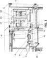
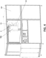
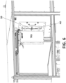
- a tray cleaning station W for ophthalmic lenses production lines LP As shown in FIGS. 1 , 7 and 8 , according to a preferred embodiment, herein it is disclosed a tray cleaning station W for ophthalmic lenses production lines LP.
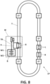
- a line as such is schematically shown in FIG. 8 .
- the tray cleaning station W comprises a conveyor T for the transport of trays B supporting the lenses, extraction means X of a tray B from the conveyor T, a chamber CH for cleaning the tray B and transfer means TR of the tray B between the extraction means X and the chamber CH.
- the present invention takes out one tray from the conveyor T by using the extraction means. Then, the tray is transferred from the extraction means to the transfer means, which introduces the tray T in the cleaning chamber CH.
- the extraction means X comprise a rotating base BX which supports two arms X1, X2.
- Each arm X1, X2 is provided in its end with a pad P1, P2 destined to press laterally a tray B.
- the base BX rotates around a rotation axis ⁇ driven by an actuator DX for rotating the axis ⁇ .
- the rotating base BX is provided with a linear actuator (not shown) for adjusting the distance between the arms X1, X2, thus allowing to clamp a tray B between the pads P1, P2 and then raise it by rotating the arms around the axis ⁇ .
- the transfer means TR comprise two clamping arms TR1, TR2, each provided in its end with a pad TR3, TR4.
- the operating principle is similar as for the extraction means X.
- the clamping arms TR1, TR2 are supported by a translating base TRS, which is guided by a guide G according to a translational movement.
- the translating base TRS comprises a linear actuator for adjusting the distance between the clamping arms TR1, TR2, thus allowing to clamp a tray B between the pads P3, P4.
- the pads P1, P2 of the arms X1, X2 of the rotating base BX are arranged to clamp the trays B on two sides of the trays B and the pads TR3, TR4 of the clamping arms TR1, TR2 are arranged to clamp the trays B on the other two sides of the trays B, thus allowing a simple transfer from the rotating to the translational means.
- a special feature of the invention is that the extraction means X are configured to carry out a rotation having an angle greater than 90o, thus allowing to overturn a tray B and void it form gross objects that could be accidentally present therein.
- a recollecting tray RB is placed on the other side of the axis ⁇ with respect to the conveyor T, thus allowing to collect the objects falling from the overturned tray B.
- the tray B is placed vertically, as shown in FIG. 5 , then ready to be inserted in a vertical slot VS for introducing the tray B into the chamber CH.
- the chamber CH comprises at least two air conducting ducts W1 vertically arranged and two sets of water conducting ducts W2 vertically arranged.
- These air conducting ducts W1 and the water conducting ducts W2 are arranged such that they define therebetween a vertical slot coincident with the vertical slot VS, the transfer means TR being arranged to introduce the tray B through the vertical slot VS and place it between the air conducting ducts W1 and the water conducting ducts W2.
- the chamber CH is completed with a sliding door SD destined to close the vertical slot VS, and actuator AD means for automatically closing it.
- the sliding door SD and the chamber CH comprise recesses S1, S2 for allowing the introduction of the clamping arms TR1, TR2, thus allowing to close the chamber CH when a tray B is being washed and move it in translational movement for exposing all its surface to the nozzles, as shown for example in FIG. 3 .
- the pads comprise adjusting means AM for adjusting the distance therebetween.
- These adjusting means can have the form of screws.
- the station comprises at least a reservoir D1 below the chamber, arranged to collect the cleaning liquids.
- the station comprises two reservoirs D1, D2 arranged below the ducts W1, W2 and a deflector D allowing to deflect the water falling to either of the reservoirs D1, D2.
- the station comprises a pump for pumping water in the chamber CH at a pressure comprised between 10 and 80 bar. These pressures have proven to be effective to efficiently remove the dirt and the dust adhered to the trays B.
- the inventive station allows to apply different cleaning programs to each tray B depending on its dirt degree.
- the station is provided with a controller, the controller being configured to apply different cleaning programs.
- the station can be provided with means for detecting the state of dirt of the trays B. These means can be based for example in an artificial vision system, or a reader of tags indicating the state of dirt of the trays B, that could have been placed/ adhered to the trays in a previous stage, either manually or automatically.
- the station has been specially conceived for its integration in a production line LP for manufacturing ophthalmic lenses L provided with treatment stations ET, as shown in FIG. 8 .
- the production line has treatment stations, for example polishing stations, connected by at least one conveyor T for the transport and transfer of trays B supporting the lenses L.
- one of the stations is a tray cleaning station W according to any of the variants disclosed above.
- An important aspect of the invention is that all the components of the station are easily accessible for maintenance, both to clean and to fix them. These tasks are usually much more complicated in a washing tunnel.
- the cleaning station is configured to be always cleaning a tray B.
- a station arranged in parallel that is, that takes out trays of the line and cleans them.
- the station is set to always be cleaning a tray. That is to say that it does not clean all the trays that go through the conveyor, but as soon as a tray has just been cleaned, the next tray that can be taken is extracted from the conveyor.
- the station has means for recognizing a dirt indicator of the tray, which may be a label previously adhered by an operator or an artificial vision system to finish cleaning trays that are travelling in the conveyors without being cleaned.
- the invention also relates to a method of washing trays in a ophthalmic lenses production line LP, which comprises the steps consisting of:
Landscapes
- Engineering & Computer Science (AREA)
- Health & Medical Sciences (AREA)
- Manufacturing & Machinery (AREA)
- Ophthalmology & Optometry (AREA)
- Mechanical Engineering (AREA)
- Cleaning In General (AREA)
- Cleaning By Liquid Or Steam (AREA)
Claims (14)
- Tablett-Reinigungsstation (W) für eine Produktionslinie (LP) für ophthalmische Linsen, wobei die Tablett-Reinigungsstation (W) ein Förderband (T) für den Transport von Tabletts (B) umfasst, das die Linsen trägt, umfassend Mittel (X) zur Entnahme eines Tabletts (B) aus dem Fördererband (T), eine Kammer (CH) zum Reinigen des Tabletts (B) und ein Übertragungsmittel (TR) des Tabletts (B) zwischen dem Extraktionsmittel (X) und der Kammer (CH), dadurch gekennzeichnet dass die Übertragungsmittel so konfiguriert sind, dass sie das Tablett (B) in die Reinigungskammer (CH) einführen, und wobei die Extraktionsmittel eine drehbare Basis (BX), die zwei Arme (X1, X2) trägt, die jeweils an ihrem Ende mit einem Polster (P1, P2) versehen sind, die dazu bestimmt sind, ein Tablett (B) seitlich zu drücken, eine Drehachse (Γ) der drehbaren Basis (BX) und ein Stellglied (DX) zum Drehen der Achse (Γ) umfassen, wobei die drehbare Basis (BX) mit einem linearen Stellglied zum Einstellen des Abstands zwischen den Armen (X1, X2) versehen ist, was das Einklemmen eines Tabletts (B) zwischen den Polstern (P1, P2) ermöglicht.
- Tablett-Reinigungsstation (W) nach einem der vorhergehenden Ansprüche, wobei die Übertragungsmittel (TR) zwei Klemmarme (TR1, TR2), die jeweils an ihrem Ende mit einem Polster (TR3, TR4) versehen sind, umfassen, eine verschiebbare Basis (TRS), die die Klemmarme (TR1, TR2) trägt, und eine Führung (G) für die Verschiebung der verschiebbaren Basis (TRS), wobei die verschiebbare Basis (TRS) ein lineares Stellglied zur Einstellung des Abstands zwischen den Klemmarmen (TR1, TR2) umfasst, so dass ein Tablett (B) zwischen die Polster (P3, P4) geklemmt werden kann.
- Tablett-Reinigungsstation (W) nach einem der Ansprüche 1 und 2, wobei die Polster (P1, P2) von den Armen (X1, X2) der drehbaren Basis (BX) so angeordnet sind, dass sie die Tabletts (B) auf zwei Seiten der Tabletts (B) einklemmen, und die Polster (TR3, TR4) der Klemmarme (TR1, TR2) so angeordnet sind, dass sie die Tabletts (B) an den beiden anderen Seiten der Tabletts (B) einklemmen.
- Tablett-Reinigungsstation (W) nach einem der vorhergehenden Ansprüche, wobei die die Extraktionsmittel (X) so konfiguriert sind, dass sie eine Drehung mit einem Winkel von mehr als 90° ausführen und so das Umkippen eines Tabletts (B) ermöglichen.
- Tablett-Reinigungsstation (W) nach einem der vorhergehenden Ansprüche, wobei die Kammer (CH) einen vertikalen Schlitz (VS) zum Einführen des Tabletts (B) aufweist.
- Tablett-Reinigungsstation (W) nach einem der vorhergehenden Ansprüche, wobei die Kammer (CH) mindestens zwei vertikal angeordnete Luftleitkanäle (W1) und mindestens zwei vertikal angeordnete Wasserleitkanäle (W2) umfasst.
- Tablett-Reinigungsstation (W) nach Anspruch 5 und 6, wobei die Luftleitkanäle (W1) und die Wasserleitkanäle (W2) so angeordnet sind, dass sie zwischen sich einen vertikalen Schlitz definieren, der mit dem vertikalen Schlitz (VS) zusammenfällt, wobei die Übertragungsmittel (TR) so angeordnet ist, dass sie das Tablett (B) durch den vertikalen Schlitz (VS) einführen und es zwischen den Luftleitkanälen (W1) und den Wasserleitkanälen (W2) platzieren.
- Tablett-Reinigungsstation (W) nach Anspruch 2 und Anspruch 5 oder Anspruch 7, wobei die Kammer (CH) eine Schiebetür (SD) umfasst, die dazu bestimmt ist, den vertikalen Schlitz (VS) zu schließen, und einem Stellgliedmittel (AD) zum automatischen Schließen der Schiebetür (SD), die Schiebetür (SD) und die Kammer (CH) umfassen Aussparungen (S1, S2), um das Einführen der Klemmarme (TR1, TR2) zu ermöglichen, so dass die Kammer (CH) geschlossen werden kann, wenn ein Tablett (B) gewaschen wird, und sie in eine Translationsbewegung versetzt werden kann, um ihre gesamte Oberfläche den Düsen auszusetzen.
- Tablett-Reinigungsstation (W) nach einem der vorhergehenden Ansprüche, wobei die Polster Einstellmittel (AM) zum Einstellen des Abstands zwischen den Polstern umfassen und die Station dann an die Behandlung verschiedener Tablettformate anpassen.
- Tablett-Reinigungsstation (W) nach Anspruch 6, die einen oder zwei Tanks (D1, D2), die unter den Kanälen (W1, W2) angeordnet sind, und eine Ablenkvorrichtung (D) umfasst, die es ermöglicht, das Wasser abzulenken in eines der beiden Reservoirs (D1, D2) fallen.
- Tablett-Reinigungsstation (W) nach einem der vorhergehenden Ansprüche, die eine Pumpe zum Pumpen von Wasser in die Kammer (CH) mit einem Druck zwischen 10 und 80 bar umfasst.
- Tablett-Reinigungsstation (W) nach einem der vorhergehenden Ansprüche, die eine Steuerung aufweist, wobei die Steuerung zur Anwendung verschiedener Reinigungsprogramme konfiguriert ist.
- Fertigungsstraße (LP) zur Herstellung von Brillengläsern (L), umfassend Behandlungsstationen (ET), die durch mindestens ein Förderband (T) für den Transport und die Übergabe zwischen den Stationen (ET) von die Linsen (L) tragenden Tabletts (B) verbunden sind), wobei die Fertigungsstraße (LP) mindestens eine Tablett-Reinigungsstation (W) nach einem der vorhergehenden Ansprüche umfasst.
- Fertigungsstraße (LP) nach Anspruch 13, wobei die Reinigungsstation so konfiguriert, dass immer ein Tablett (B) gereinigt wird.
Applications Claiming Priority (1)
| Application Number | Priority Date | Filing Date | Title |
|---|---|---|---|
| PCT/ES2018/070578 WO2020043923A1 (es) | 2018-08-29 | 2018-08-29 | Estación de limpieza de bandejas y línea de producción para fabricar lentes oftálmicas provista de dicha estación |
Publications (3)
| Publication Number | Publication Date |
|---|---|
| EP3845320A1 EP3845320A1 (de) | 2021-07-07 |
| EP3845320C0 EP3845320C0 (de) | 2024-10-16 |
| EP3845320B1 true EP3845320B1 (de) | 2024-10-16 |
Family
ID=64402226
Family Applications (1)
| Application Number | Title | Priority Date | Filing Date |
|---|---|---|---|
| EP18807105.4A Active EP3845320B1 (de) | 2018-08-29 | 2018-08-29 | Tablettreinigungsstation und produktionslinie zur herstellung von ophthalmischen linsen mit dieser station |
Country Status (2)
| Country | Link |
|---|---|
| EP (1) | EP3845320B1 (de) |
| WO (1) | WO2020043923A1 (de) |
Family Cites Families (9)
| Publication number | Priority date | Publication date | Assignee | Title |
|---|---|---|---|---|
| US3675665A (en) * | 1965-01-15 | 1972-07-11 | Ind Washing Machine Corp | Case washing machine |
| US3345994A (en) * | 1965-09-20 | 1967-10-10 | Grassland Dairy Products Inc | Apparatus for cleaning articles |
| FR2159212B1 (de) * | 1971-11-12 | 1974-05-31 | Peugeot & Renault | |
| DE3436865A1 (de) * | 1984-10-08 | 1986-06-12 | Ulrich 8402 Neutraubling Klotzki | Vorrichtung zum reinigen von flaschenkaesten o.dgl. |
| DE3515829A1 (de) * | 1985-05-02 | 1986-11-06 | Siemens AG, 1000 Berlin und 8000 München | Verfahren zur reinigung von auf foerderbahnen fortbewegten werkstuecktraegern und waschgeraet zur durchfuehrung des verfahrens |
| ITTO20050260A1 (it) * | 2005-04-18 | 2006-10-19 | R E A S N C Di Sassi E Baudin | Impianto, tunnel, dispositivo e metodo per il lavaggio di oggetti con vapore |
| IE20070096A1 (en) | 2007-02-15 | 2008-02-20 | Bausch & Lomb | System and method for cleaning process trays |
| FR2959643B1 (fr) | 2010-05-07 | 2013-06-14 | Applic Des Silicones Alimentaires Soc D | Machine de lavage en ligne pour ustensiles de cuisson |
| KR101470284B1 (ko) | 2014-06-02 | 2014-12-08 | 피알캠(주) | 컨베이어 타입의 에어 분사 및 흡입 혼합형 세척장치 |
-
2018
- 2018-08-29 EP EP18807105.4A patent/EP3845320B1/de active Active
- 2018-08-29 WO PCT/ES2018/070578 patent/WO2020043923A1/es not_active Ceased
Also Published As
| Publication number | Publication date |
|---|---|
| EP3845320C0 (de) | 2024-10-16 |
| EP3845320A1 (de) | 2021-07-07 |
| WO2020043923A1 (es) | 2020-03-05 |
Similar Documents
| Publication | Publication Date | Title |
|---|---|---|
| US6637446B2 (en) | Integrated substrate processing system | |
| US10562076B2 (en) | Substrate cleaning apparatus, substrate cleaning method, and substrate processing apparatus | |
| US8958064B2 (en) | Inspection device with rotatable lighting element housing | |
| JP6329813B2 (ja) | 搬送ロボット | |
| KR20210046305A (ko) | 마늘꼭지 자동절단장치 | |
| US20180043403A1 (en) | Method for machine-cleaning workpieces and/or machine components, and cleaning system | |
| CN102005499A (zh) | 太阳能电池晶圆盒输送装置及其太阳能电池晶圆纹理装置 | |
| US6575290B2 (en) | Automatic empty container return machine equipped with self-cleaning arrangement | |
| CN107283259B (zh) | 一种用于光学镜头抛光机的自动上下料设备的上下料方法 | |
| EP3845320A1 (de) | Tablettreinigungsstation und produktionslinie zur herstellung von brillengläsern mit dieser station | |
| CN208743931U (zh) | 产品镭雕与清洗一体化装置 | |
| CN109607186A (zh) | 一种工件移栽智能设备及工件移栽方法 | |
| CN105642609B (zh) | 一种吊篮转盘式ic卡超声波清洗机 | |
| CN211839290U (zh) | 芯片清洗机及其上下料机构 | |
| KR20250120225A (ko) | 안경 렌즈와 같은 렌즈를 세척하기 위한 기계 및 방법 | |
| KR102785703B1 (ko) | 복수의 재생 웨이퍼들을 세정 및 건조하는 장치 | |
| KR101130888B1 (ko) | 화학 기계적 연마 장치의 캐리어 헤드의 세정 유닛 및 이를 이용한 이동식 화학 기계적 연마 시스템 | |
| CN106166702B (zh) | 一种带除尘的自动检测磨床 | |
| CN109860079A (zh) | 一种加密芯片的清洗装置 | |
| CN112750740B (zh) | 输送模块、切割装置以及切割品的制造方法 | |
| CN209859924U (zh) | 硅片清洗系统 | |
| KR101121208B1 (ko) | 판유리 이송장치 및 이를 구비하는 판유리 처리장치 | |
| KR20230094790A (ko) | 필터 세척 장치 | |
| JP6256070B2 (ja) | 有軌道台車 | |
| WO2017086877A1 (en) | Apparatus and method for cleaning a wafer table surface and/or an object disposed thereon |
Legal Events
| Date | Code | Title | Description |
|---|---|---|---|
| STAA | Information on the status of an ep patent application or granted ep patent |
Free format text: STATUS: UNKNOWN |
|
| STAA | Information on the status of an ep patent application or granted ep patent |
Free format text: STATUS: THE INTERNATIONAL PUBLICATION HAS BEEN MADE |
|
| STAA | Information on the status of an ep patent application or granted ep patent |
Free format text: STATUS: REQUEST FOR EXAMINATION WAS MADE |
|
| PUAI | Public reference made under article 153(3) epc to a published international application that has entered the european phase |
Free format text: ORIGINAL CODE: 0009012 |
|
| 17P | Request for examination filed |
Effective date: 20210329 |
|
| AK | Designated contracting states |
Kind code of ref document: A1 Designated state(s): AL AT BE BG CH CY CZ DE DK EE ES FI FR GB GR HR HU IE IS IT LI LT LU LV MC MK MT NL NO PL PT RO RS SE SI SK SM TR |
|
| DAV | Request for validation of the european patent (deleted) | ||
| DAX | Request for extension of the european patent (deleted) | ||
| STAA | Information on the status of an ep patent application or granted ep patent |
Free format text: STATUS: EXAMINATION IS IN PROGRESS |
|
| 17Q | First examination report despatched |
Effective date: 20230328 |
|
| GRAP | Despatch of communication of intention to grant a patent |
Free format text: ORIGINAL CODE: EPIDOSNIGR1 |
|
| STAA | Information on the status of an ep patent application or granted ep patent |
Free format text: STATUS: GRANT OF PATENT IS INTENDED |
|
| INTG | Intention to grant announced |
Effective date: 20240508 |
|
| GRAS | Grant fee paid |
Free format text: ORIGINAL CODE: EPIDOSNIGR3 |
|
| GRAA | (expected) grant |
Free format text: ORIGINAL CODE: 0009210 |
|
| STAA | Information on the status of an ep patent application or granted ep patent |
Free format text: STATUS: THE PATENT HAS BEEN GRANTED |
|
| AK | Designated contracting states |
Kind code of ref document: B1 Designated state(s): AL AT BE BG CH CY CZ DE DK EE ES FI FR GB GR HR HU IE IS IT LI LT LU LV MC MK MT NL NO PL PT RO RS SE SI SK SM TR |
|
| REG | Reference to a national code |
Ref country code: GB Ref legal event code: FG4D |
|
| REG | Reference to a national code |
Ref country code: DE Ref legal event code: R096 Ref document number: 602018075555 Country of ref document: DE Ref country code: CH Ref legal event code: EP |
|
| REG | Reference to a national code |
Ref country code: IE Ref legal event code: FG4D |
|
| U01 | Request for unitary effect filed |
Effective date: 20241105 |
|
| U07 | Unitary effect registered |
Designated state(s): AT BE BG DE DK EE FI FR IT LT LU LV MT NL PT RO SE SI Effective date: 20241119 |
|
| PG25 | Lapsed in a contracting state [announced via postgrant information from national office to epo] |
Ref country code: HR Free format text: LAPSE BECAUSE OF FAILURE TO SUBMIT A TRANSLATION OF THE DESCRIPTION OR TO PAY THE FEE WITHIN THE PRESCRIBED TIME-LIMIT Effective date: 20241016 Ref country code: IS Free format text: LAPSE BECAUSE OF FAILURE TO SUBMIT A TRANSLATION OF THE DESCRIPTION OR TO PAY THE FEE WITHIN THE PRESCRIBED TIME-LIMIT Effective date: 20250216 |
|
| PG25 | Lapsed in a contracting state [announced via postgrant information from national office to epo] |
Ref country code: ES Free format text: LAPSE BECAUSE OF FAILURE TO SUBMIT A TRANSLATION OF THE DESCRIPTION OR TO PAY THE FEE WITHIN THE PRESCRIBED TIME-LIMIT Effective date: 20241016 |
|
| PG25 | Lapsed in a contracting state [announced via postgrant information from national office to epo] |
Ref country code: NO Free format text: LAPSE BECAUSE OF FAILURE TO SUBMIT A TRANSLATION OF THE DESCRIPTION OR TO PAY THE FEE WITHIN THE PRESCRIBED TIME-LIMIT Effective date: 20250116 |
|
| PG25 | Lapsed in a contracting state [announced via postgrant information from national office to epo] |
Ref country code: GR Free format text: LAPSE BECAUSE OF FAILURE TO SUBMIT A TRANSLATION OF THE DESCRIPTION OR TO PAY THE FEE WITHIN THE PRESCRIBED TIME-LIMIT Effective date: 20250117 |
|
| PG25 | Lapsed in a contracting state [announced via postgrant information from national office to epo] |
Ref country code: PL Free format text: LAPSE BECAUSE OF FAILURE TO SUBMIT A TRANSLATION OF THE DESCRIPTION OR TO PAY THE FEE WITHIN THE PRESCRIBED TIME-LIMIT Effective date: 20241016 |
|
| PG25 | Lapsed in a contracting state [announced via postgrant information from national office to epo] |
Ref country code: RS Free format text: LAPSE BECAUSE OF FAILURE TO SUBMIT A TRANSLATION OF THE DESCRIPTION OR TO PAY THE FEE WITHIN THE PRESCRIBED TIME-LIMIT Effective date: 20250116 |
|
| PG25 | Lapsed in a contracting state [announced via postgrant information from national office to epo] |
Ref country code: SM Free format text: LAPSE BECAUSE OF FAILURE TO SUBMIT A TRANSLATION OF THE DESCRIPTION OR TO PAY THE FEE WITHIN THE PRESCRIBED TIME-LIMIT Effective date: 20241016 |
|
| PG25 | Lapsed in a contracting state [announced via postgrant information from national office to epo] |
Ref country code: SK Free format text: LAPSE BECAUSE OF FAILURE TO SUBMIT A TRANSLATION OF THE DESCRIPTION OR TO PAY THE FEE WITHIN THE PRESCRIBED TIME-LIMIT Effective date: 20241016 |
|
| PG25 | Lapsed in a contracting state [announced via postgrant information from national office to epo] |
Ref country code: CZ Free format text: LAPSE BECAUSE OF FAILURE TO SUBMIT A TRANSLATION OF THE DESCRIPTION OR TO PAY THE FEE WITHIN THE PRESCRIBED TIME-LIMIT Effective date: 20241016 |
|
| PLBE | No opposition filed within time limit |
Free format text: ORIGINAL CODE: 0009261 |
|
| STAA | Information on the status of an ep patent application or granted ep patent |
Free format text: STATUS: NO OPPOSITION FILED WITHIN TIME LIMIT |
|
| U20 | Renewal fee for the european patent with unitary effect paid |
Year of fee payment: 8 Effective date: 20250718 |
|
| 26N | No opposition filed |
Effective date: 20250717 |
|
| REG | Reference to a national code |
Ref country code: CH Ref legal event code: H13 Free format text: ST27 STATUS EVENT CODE: U-0-0-H10-H13 (AS PROVIDED BY THE NATIONAL OFFICE) Effective date: 20260324 |
|
| PG25 | Lapsed in a contracting state [announced via postgrant information from national office to epo] |
Ref country code: MC Free format text: LAPSE BECAUSE OF FAILURE TO SUBMIT A TRANSLATION OF THE DESCRIPTION OR TO PAY THE FEE WITHIN THE PRESCRIBED TIME-LIMIT Effective date: 20241016 |
|
| PG25 | Lapsed in a contracting state [announced via postgrant information from national office to epo] |
Ref country code: CH Free format text: LAPSE BECAUSE OF NON-PAYMENT OF DUE FEES Effective date: 20250831 |
|
| GBPC | Gb: european patent ceased through non-payment of renewal fee |
Effective date: 20250829 |