EP3845330A1 - Leichtreduktionsverfahren zum stranggiessen von kombination aus brammenglattwalze und walze - Google Patents
Leichtreduktionsverfahren zum stranggiessen von kombination aus brammenglattwalze und walze Download PDFInfo
- Publication number
- EP3845330A1 EP3845330A1 EP19853592.4A EP19853592A EP3845330A1 EP 3845330 A1 EP3845330 A1 EP 3845330A1 EP 19853592 A EP19853592 A EP 19853592A EP 3845330 A1 EP3845330 A1 EP 3845330A1
- Authority
- EP
- European Patent Office
- Prior art keywords
- roll
- bloom
- convex
- casting
- straight line
- Prior art date
- Legal status (The legal status is an assumption and is not a legal conclusion. Google has not performed a legal analysis and makes no representation as to the accuracy of the status listed.)
- Granted
Links
Images


Classifications
-
- B—PERFORMING OPERATIONS; TRANSPORTING
- B21—MECHANICAL METAL-WORKING WITHOUT ESSENTIALLY REMOVING MATERIAL; PUNCHING METAL
- B21B—ROLLING OF METAL
- B21B1/00—Metal-rolling methods or mills for making semi-finished products of solid or profiled cross-section; Sequence of operations in milling trains; Layout of rolling-mill plant, e.g. grouping of stands; Succession of passes or of sectional pass alternations
- B21B1/46—Metal-rolling methods or mills for making semi-finished products of solid or profiled cross-section; Sequence of operations in milling trains; Layout of rolling-mill plant, e.g. grouping of stands; Succession of passes or of sectional pass alternations for rolling metal immediately subsequent to continuous casting
-
- B—PERFORMING OPERATIONS; TRANSPORTING
- B22—CASTING; POWDER METALLURGY
- B22D—CASTING OF METALS; CASTING OF OTHER SUBSTANCES BY THE SAME PROCESSES OR DEVICES
- B22D11/00—Continuous casting of metals, i.e. casting in indefinite lengths
- B22D11/16—Controlling or regulating processes or operations
- B22D11/20—Controlling or regulating processes or operations for removing cast stock
- B22D11/201—Controlling or regulating processes or operations for removing cast stock responsive to molten metal level or slag level
- B22D11/202—Controlling or regulating processes or operations for removing cast stock responsive to molten metal level or slag level by measuring temperature
-
- B—PERFORMING OPERATIONS; TRANSPORTING
- B22—CASTING; POWDER METALLURGY
- B22D—CASTING OF METALS; CASTING OF OTHER SUBSTANCES BY THE SAME PROCESSES OR DEVICES
- B22D11/00—Continuous casting of metals, i.e. casting in indefinite lengths
- B22D11/12—Accessories for subsequent treating or working cast stock in situ
- B22D11/1206—Accessories for subsequent treating or working cast stock in situ for plastic shaping of strands
-
- B—PERFORMING OPERATIONS; TRANSPORTING
- B22—CASTING; POWDER METALLURGY
- B22D—CASTING OF METALS; CASTING OF OTHER SUBSTANCES BY THE SAME PROCESSES OR DEVICES
- B22D11/00—Continuous casting of metals, i.e. casting in indefinite lengths
- B22D11/12—Accessories for subsequent treating or working cast stock in situ
- B22D11/128—Accessories for subsequent treating or working cast stock in situ for removing
- B22D11/1287—Rolls; Lubricating, cooling or heating rolls while in use
-
- B—PERFORMING OPERATIONS; TRANSPORTING
- B22—CASTING; POWDER METALLURGY
- B22D—CASTING OF METALS; CASTING OF OTHER SUBSTANCES BY THE SAME PROCESSES OR DEVICES
- B22D11/00—Continuous casting of metals, i.e. casting in indefinite lengths
- B22D11/16—Controlling or regulating processes or operations
-
- B—PERFORMING OPERATIONS; TRANSPORTING
- B22—CASTING; POWDER METALLURGY
- B22D—CASTING OF METALS; CASTING OF OTHER SUBSTANCES BY THE SAME PROCESSES OR DEVICES
- B22D11/00—Continuous casting of metals, i.e. casting in indefinite lengths
- B22D11/16—Controlling or regulating processes or operations
- B22D11/20—Controlling or regulating processes or operations for removing cast stock
- B22D11/207—Controlling or regulating processes or operations for removing cast stock responsive to thickness of solidified shell
Definitions
- the present disclosure pertains to the field of metal casting, and particularly relates to a method for in-situ post-treatment or post-processing of a cast slab.
- the surface of a casting slab solidifies earlier than the inside of the casting slab due to external cooling. As a result, the surface shrinks more than the inside. As the solidification and crystallization end, columnar crystals on both sides of some local areas are bridged. When liquid confined under the bridge solidifies, replenishment of molten steel from above the bridge to liquid phase cavity is blocked. Then, shrinkage cavity and porosity are generated when the molten steel under the bridge solidifies. With the formation of shrinkage cavity and porosity, the vacuum shrinkage cavity may suck solute-rich liquid between dendritic crystals and allow it to flow toward the center. At the same time, macro-segregation occurs.
- soft reduction is equivalent to compression casting, it has the effect of eliminating shrinkage cavity, porosity and macro-segregation at the same time.
- the flat-roll soft reduction technology for casting slabs has been widely used in the field of continuous casting.
- the existing technology employs a pair of flat rolls for compression. Due to the exchangeability of tension levelers, they are all made the same, so the reduction force is also the same. As a result, the pressure applied by an upstream tension leveler is excessive while the pressure applied by a downstream tension leveler is insufficient. As an increasing quantity of high-alloy steel is produced, this problem has become more prominent. To address this problem, there is proposed a technology according to which a convex roll is used to achieve more effective soft reduction of unsolidified parts.
- This technical solution utilizes a constant-curvature protuberance-free convex roll (drum roll) which is installed at a position having a solid fraction of 0.2 to apply a large reduction, and a convex roll having a protuberance and a gradient curvature is located at the solidification end. Reduction with a large amount of deformation is only utilized sequentially at two positions, namely the center having a solid fraction of 0.2 and the solidification end, in an attempt to overcome the quality defects of segregation of chemical components, and shrinkage cavity and serious porosity in the solidification center.
- soft reduction is equivalent to compression casting, wherein the reduction is used to compensate for the current shrinkage of molten steel and restrict the flow of molten steel rich in low-melting impurities between dendritic crystals to the center.
- An excessive reduction is not conducive to the alleviation of solidification segregation.
- the technical problem to be solved by the present disclosure is to provide a soft reduction method for a continuous casting bloom with a combination of a flat roll and a convex roll.
- the convex roll is used to partially reduce the reduction force of a tension leveler and reduce the withdrawal resistance.
- the convex rolls on different tension levelers include protuberances having different lengths, and the final indentation profile generated on the upper surface of the casting bloom has a wider opening. This can avoid occurrence of folding defects in a subsequent steel rolling process, and it is more conducive to reducing the reduction force, even more conducive to reducing the reduction force of the convex roll tension leveler.
- the technical solution of the present disclosure is to provide a soft reduction method for a continuous casting bloom with a combination of a flat roll and a convex roll, comprising sequentially arranging a plurality of tension levelers on a continuous casting line to compression cast the casting bloom, characterized by:
- a flat roll tension leveler is used to perform compression casting on the casting bloom; and when the solid fraction is f s > 0.5, a convex roll tension leveler is used to perform compression casting on the casting bloom.
- the reduction rate is obtained by dividing the reduction with the thickness of the casting bloom.
- a flat roll tension leveler is still used to perform compression casting on the casting bloom.
- a convex roll tension leveler is used to perform compression casting on the casting bloom.
- a combination of a flat roll tension leveler and a convex roll tension leveler is used in the soft reduction method to control the soft reduction of the cast bloom at the solidification end to reduce the center porosity, shrinkage cavity and segregation of the cast bloom, and improve the internal quality of a rolled product.
- the soft reduction method can reduce the reduction force of the convex roll tension leveler, and at the same time reduce the withdrawal resistance in the continuous casting process.
- the upper roll of the convex roll tension leveler is a convex roll which can be raised or lowered to adjust the roll gap, and the convex roll is connected to a motor and a speed reducer.
- the lower roll of the convex roll tension leveler is a flat roll.
- the upper roll and the lower roll are connected by a frame, and a reduction force is applied to the casting bloom therebetween through four pairs of driving hydraulic cylinders.
- the upper roll is a convex roll, and it is a driving roll.
- the lower roll is a flat roll, and it is a fixed driven roll.
- the profile curve of the working part of the convex roll body consists of a first straight line section AB, a first transition curve section BC, a second straight line section CD, a second transition curve section DE, and a third straight line section EF connected in sequence, wherein the first straight line section AB and the third straight line section EF are arranged coaxially or coplanarly; the second straight line section CD and the first straight line section AB or the third straight line section EF are arranged in parallel; and the first curve section BC and the second curve section DE are each composed of a sine curve, or composed of two arc lines that are tangent to each other, one inwardly concave, and the other outwardly convex, the radii of the two arcs being equal or unequal.
- the first transition curve section BC, the second straight line section CD and the second transition curve section DE form a protruding structure in the form of a protube
- the opening of the indentation profile generated on the upper surface of the cast bloom is wider. This can avoid occurrence of folding defects in a subsequent steel rolling process, and it is more conducive to reducing the reduction force, even more conducive to reducing the reduction force of the convex roll tension leveler.
- the second transition curve DE is mirror-symmetrical to the first transition curve BC, and the mirror-symmetrical centerline is a straight line that passes through the midpoint of the second straight line section CD and is perpendicular to the second straight line section CD.
- the opening of the indentation profile generated on the upper surface of the casting bloom is equal to the length of the second straight line section CD of the convex roll body.
- the length of the second straight line section CD of the convex roll body of each tension leveler depends on the width D of the unsolidified two-phase region of the continuous casting bloom when it arrives at the position of the tension leveler.
- the length of the second straight line section CD of the convex roll body of each tension leveler is ⁇ D+40 mm.
- the present disclosure includes the following advantages:
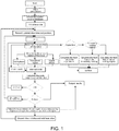
- Fig. 1 is a flow chart for calculation of solidification heat transfer in continuous casting.
- start represents start of calculation
- input parameters represents input of the physical parameters of the steel, steel grade, drawing speed, superheat degree, etc.
- search for a water volume database represents searching for the cooling water volume in each cooling loop in each cooling zone
- initialize a slice represents initialization of a slice at the beginning of the finite element slicing calculation
- record (update) slice time and position represents recording (updating) the time when the slice is formed and the position at which the slice arrives
- determination determine the position of the slicing point” represents determining whether the slicing point is in the crystallizer or in the secondary cooling region; if it's in the "crystallizer", calculate the heat flow in the crystallizer; if it's in the "secondary cooling region”, calculate the heat flow in each secondary cooling region; if the "secondary cooling region” is not a water cooling zone but an air cooling zone
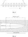
- the arrow in the figure indicates the direction of the continuous casting process route, i.e., the advancing direction of the casting bloom.
- Fig. 3 shows the thicknesses of the two-phase region and the solid-phase region of the casting bloom.
- the tension levelers far from the solidification end (that is, the upstream tension levelers whose number i is smaller, wherein the i value may be selected from 1-4) can meet the requirement of the corresponding part of the casting bloom for soft reduction, because the bloom shell is thin, the temperature of the casting bloom is high, and thus a smaller soft reduction force is needed.
- the tension levelers closer to the solidification end (that is, the downstream tension levelers whose number i is larger, wherein the i value may be selected from 5- 8) cannot meet the requirement of the corresponding part of the casting bloom for soft reduction, because the bloom shell is thick, the temperature of the casting bloom is low, and thus a larger soft reduction force is needed.
- the technical solution of the present disclosure utilizes a soft reduction method combining a flat roll and a convex roll, wherein the upstream tension levelers still use a flat roll scheme, while the downstream tension levelers use a convex roll scheme.
- the boundary between the upstream tension levelers and the downstream tension levelers is usually related with f s .
- the inventors recommend that when the solid fraction of the casting bloom is f s ⁇ 0.5, flat roll tension levelers are used to perform compression casting on the casting bloom; for solid fraction f s >0.5, convex roll tension levelers are used to perform compression casting on the casting bloom.
- Fig. 4 is a schematic view showing a convex roll tension leveler.
- the upper roll 1 is a convex roll which is a driving roll. It can be raised or lowered to adjust the roll gap, and is connected to a motor and a speed reducer.
- the lower roll 3 is a flat roll which is a fixed driven roll. The upper and lower rolls are connected by a frame, and a reduction force is applied to the casting bloom therebetween through four pairs of driving hydraulic cylinders.
- the casting bloom 2 is located between the upper roll and the lower roll.
- Fig. 5 is a schematic structural view showing the profile of the convex roll of the convex roll tension leveler in the present technical solution. It can be seen from the figure that the profile curve of the working part of roll body of the convex shape roll (convex roll for short) consists of a first straight line section AB, a first transition curve section BC, a second straight line section CD, a second transition curve section DE, and a third straight line section EF.
- the first transition curve section BC and the second transition curve section DE are each composed of a sine curve, or composed of two arc lines that are respectively tangent to adjacent straight line sections, one inwardly concave, and the other outwardly convex.
- the radii of the two arcs are equal or unequal.
- the first transition curve section BC, the second straight line section CD and the second transition curve section DE form a protruding structure 4 in the form of a protuberance on the surface of the convex roll.
- point B is the origin of coordinates; the x-axis is parallel to the central axis of the roll; and the y-axis is perpendicular to the central axis of the roll.
- n is a multiple of the height H of the protuberance. That is, the projection length of the first transition curve section BC of the protuberance on the axis is nH.
- the second transition curve DE can be formed as a mirror image of the first transition curve BC about a center line passing through the midpoint of the line section CD.
- the length of the second straight line section CD in the middle of the convex roll body depends on the width D of the unsolidified two-phase region of the continuous casting bloom when it arrives at the position of each tension leveler in Fig. 3 .
- the width D of the unsolidified two-phase region varies as the casting bloom arrives at the positions of the various tension levelers
- the lengths of the second straight line sections (also known as the middle straight line sections) CD of the various convex rolls are also different in accordance with the various positions of the tension levelers.
- the D i value varies for different casting speeds, steel grades, superheat degrees, and cooling intensities.
- the length of the second straight line section CD i of the corresponding convex roll should be greater than the width D i of the unsolidified two-phase region when the casting bloom arrives at the position of each tension leveler.
- a small bias flow does not have much impact on the flat roll tension leveler, because the flat roll can always compress the unsolidified two-phase region in the center of the casting bloom.
- the protruding part that is, the aforementioned protuberance
- the convex roll can also compress the unsolidified two-phase region in the center of the casting bloom.
- the height H of the protuberance is determined according to the total shrinkage and the linear shrinkage of the solidified volume in the reduction zone for all tension levelers. With versatility taken into account, it is 30% larger than the theoretically calculated value.
- Fig. 6 shows the profile of the indentation generated on the upper surface of the final casted bloom after the end of the soft reduction using reduction rolls having protuberances of different lengths.
- the opening of the indentation T is widened (more accurately, it shows a trend of gradual widening from the bottom of the opening upward, and it's approximately an inverted antiparallelogram). This can avoid occurrence of folding defects in a subsequent steel rolling process, and it is more conducive to reducing the reduction force of the convex roll tension leveler.
- the soft reduction method for a continuous casting bloom with a combination of a flat roll and a convex roll is used to control the soft reduction at the solidification end, and it is used comprehensively to reduce center porosity, shrinkage cavity and segregation of the cast bloom, and improve the internal quality of a rolled material.
- the soft reduction method for a continuous casting bloom with a combination of a flat roll and a convex roll prevents the large deformation resistance of the solidified shells on both sides, and the reduction force of the convex roll tension leveler may be reduced.
- f s 0.9-1.0
- heavy reduction can be applied to the solidification end of the casting bloom to increase the density of the center of the casting bloom.
- the friction is reduced, so the withdrawal resistance is also reduced in the continuous casting process of the casting bloom.
- the reduction is dispersed.
- the reduction rolls with protuberances of different lengths provide a wider opening to the indentation profile generated on the upper surface of the cast bloom at the end. This can avoid occurrence of folding defects in a subsequent steel rolling process, and it is more conducive to reducing the reduction force of the convex roll tension leveler.
- tension levelers were disposed sequentially in the advancing direction of the continuous casting process line, and the serial numbers of the tension levelers were No. 1 to No. 9.
- model calculation was performed on the solidification heat transfer and liquid phase cavity in the continuous casting of a bloom according to the theories of continuous casting and casting molding.
- a three-dimensional temperature field profile, a two-phase region thickness, a solid-phase region thickness and a solid fraction were calculated from various steel grades, drawing speeds, cooling conditions, and superheat degrees when the casting bloom arrived at a position corresponding to each tension leveler.
- positions of rolls starting and ending reduction were determined, and associated with each tension leveler on the continuous casting line.
- the results are as follows: Tension levelers Nos. 1-5 were equipped with flat rolls. The working body of the roll had a length of 500 mm, and a roll diameter of 500 mm.
- Tension leveler No. 6 had a convex roll.
- the working body of this roll had a length of 500 mm, and a roll diameter of 500 mm.
- the straight line sections at both ends i.e. the first and third straight line sections mentioned above, the same below
- the middle straight line section i.e. the second straight line section mentioned above, the same below
- CD had a length of 240 mm.
- the projection length of the transition curves BC and DE i.e. the first transition curve BC and the second transition curve DE mentioned above, the same below in the horizontal direction was 40mm.
- Tension leveler No. 7 had a convex roll.
- the working body of this roll had a length of 500 mm, and a roll diameter of 500 mm.
- the middle straight line section CD had a length of 210 mm.
- the projection length of the transition curves BC and DE in the horizontal direction was 40mm.
- Tension leveler No. 8 had a convex roll.
- the working body of this roll had a length of 500 mm, and a roll diameter of 500 mm.
- the middle straight line section CD had a length of 180 mm.
- the projection length of the transition curves BC and DE in the horizontal direction was 40mm.
- Tension leveler No. 9 had a convex roll.
- the working body of this roll had a length of 500 mm, and a roll diameter of 500 mm.
- the middle straight line section CD had a length of 150 mm.
- the projection length of the transition curves BC and DE in the horizontal direction was 40mm.
- Tension levelers Nos. 1-5 were equipped with flat rolls.
- the working body of the roll had a length of 500 mm, and a roll diameter of 500 mm.
- Tension leveler No. 6 had a convex roll.
- the working body of this roll had a length of 500 mm, and a roll diameter of 500 mm.
- the middle straight line section CD had a length of 250 mm.
- the projection length of the transition curves BC and DE in the horizontal direction was 40 mm.
- Tension leveler No. 7 had a convex roll.
- the working body of this roll had a length of 500 mm, and a roll diameter of 500 mm.
- the middle straight line section CD had a length of 230 mm.
- the projection length of the transition curves BC and DE in the horizontal direction was 40 mm.
- Tension leveler No. 8 had a convex roll.
- the working body of this roll had a length of 500 mm, and a roll diameter of 500 mm.
- the middle straight line section CD had a length of 210 mm.
- the projection length of the transition curves BC and DE in the horizontal direction was 40mm.
- Tension leveler No. 9 had a convex roll.
- the working body of this roll had a length of 500 mm, and a roll diameter of 500 mm.
- the middle straight line section CD had a length of 190 mm.
- the projection length of the transition curves BC and DE in the horizontal direction was 40 mm.
- Tension levelers Nos. 1-5 were equipped with flat rolls.
- the working body of the roll had a length of 500 mm, and a roll diameter of 500 mm.
- Tension leveler No. 6 had a convex roll.
- the working body of this roll had a length of 500 mm, and a roll diameter of 500 mm.
- the middle straight line section CD had a length of 240 mm.
- the projection length of the transition curves BC and DE in the horizontal direction was 40 mm.
- Tension leveler No. 7 had a convex roll.
- the working body of this roll had a length of 500 mm, and a roll diameter of 500 mm.
- the middle straight line section CD had a length of 210 mm.
- the projection length of the transition curves BC and DE in the horizontal direction was 40 mm.
- Tension leveler No. 8 had a convex roll.
- the working body of this roll had a length of 500 mm, and a roll diameter of 500 mm.
- the middle straight line section CD had a length of 180 mm.
- the projection length of the transition curves BC and DE in the horizontal direction was 40 mm.
- Tension levelers No. 9 was equipped with flat rolls.
- the working body of the roll had a length of 500 mm, and a roll diameter of 500 mm.
- Tension levelers Nos. 1-4 were equipped with flat rolls.
- the working body of the roll had a length of 500 mm, and a roll diameter of 500 mm.
- Tension leveler No. 5 had a convex roll.
- the working body of this roll had a length of 500 mm, and a roll diameter of 500 mm.
- the middle straight line section CD had a length of 250 mm.
- the projection length of the transition curves BC and DE in the horizontal direction was 40 mm.
- Tension leveler No. 6 had a convex roll.
- the working body of this roll had a length of 500 mm, and a roll diameter of 500 mm.
- the middle straight line section CD had a length of 230 mm.
- the projection length of the transition curves BC and DE in the horizontal direction was 40 mm.
- Tension leveler No. 7 had a convex roll.
- the working body of this roll had a length of 500 mm, and a roll diameter of 500 mm.
- the middle straight line section CD had a length of 210 mm.
- the projection length of the transition curves BC and DE in the horizontal direction was 40 mm.
- Tension leveler No. 8 had a convex roll.
- the working body of this roll had a length of 500 mm, and a roll diameter of 500 mm.
- the middle straight line section CD had a length of 190 mm.
- the projection length of the transition curves BC and DE in the horizontal direction was 40 mm.
- Tension levelers No. 9 was equipped with flat rolls.
- the working body of the roll had a length of 500 mm, and a roll diameter of 500 mm.
- a three-dimensional temperature field profile, a two-phase region thickness, a solid-phase region thickness and a solid fraction f s when the casting bloom arrives at the position of each tension leveler are calculated from various steel grades, drawing speeds, cooling conditions, and superheat degrees.
- the positions of rolls starting and ending reduction are determined based on the model calculation.
- the reduction of each roll is determined according to the volume shrinkage.
- the reduction of a single roll is not greater than 5 mm.
- the solidified bloom shells on both sides are prevented from generating large deformation resistance, which can reduce the reduction force of the convex roll tension leveler.
- f s 0.9-1.0
- heavy reduction can be applied to the solidification end of the casting bloom to increase the density of the center of the casting bloom.
- the friction is reduced, so the withdrawal resistance is also reduced in the continuous casting process of the casting bloom.
- the disclosure can be widely applied in the field of metal casting.
Landscapes
- Engineering & Computer Science (AREA)
- Mechanical Engineering (AREA)
- Continuous Casting (AREA)
Applications Claiming Priority (2)
| Application Number | Priority Date | Filing Date | Title |
|---|---|---|---|
| CN201811014372.4A CN110871265B (zh) | 2018-08-31 | 2018-08-31 | 连铸大方坯平辊和凸辊组合的轻压下方法 |
| PCT/CN2019/101037 WO2020042924A1 (zh) | 2018-08-31 | 2019-08-16 | 连铸大方坯平辊和凸辊组合的轻压下方法 |
Publications (3)
| Publication Number | Publication Date |
|---|---|
| EP3845330A1 true EP3845330A1 (de) | 2021-07-07 |
| EP3845330A4 EP3845330A4 (de) | 2021-09-22 |
| EP3845330B1 EP3845330B1 (de) | 2024-04-10 |
Family
ID=69643850
Family Applications (1)
| Application Number | Title | Priority Date | Filing Date |
|---|---|---|---|
| EP19853592.4A Active EP3845330B1 (de) | 2018-08-31 | 2019-08-16 | Leichtreduktionsverfahren zum stranggiessen von kombination aus brammenglattwalze und walze |
Country Status (6)
| Country | Link |
|---|---|
| US (1) | US11207729B2 (de) |
| EP (1) | EP3845330B1 (de) |
| JP (1) | JP7234347B2 (de) |
| KR (1) | KR102417154B1 (de) |
| CN (1) | CN110871265B (de) |
| WO (1) | WO2020042924A1 (de) |
Families Citing this family (12)
| Publication number | Priority date | Publication date | Assignee | Title |
|---|---|---|---|---|
| CN112845609B (zh) * | 2020-12-03 | 2022-06-14 | 联峰钢铁(张家港)有限公司 | 一种改善轴承钢芯部显微孔隙的控轧方法 |
| CN115401178B (zh) * | 2021-05-28 | 2023-07-07 | 宝山钢铁股份有限公司 | 一种改善齿轮钢内部质量的压下工艺确定方法 |
| CN113523216B (zh) * | 2021-06-23 | 2024-04-05 | 中冶南方连铸技术工程有限责任公司 | 连铸单辊重压下控制方法及系统 |
| CN114734011A (zh) * | 2022-04-18 | 2022-07-12 | 中天钢铁集团有限公司 | 一种提高连铸方坯内部质量的连铸方法 |
| CN114833320B (zh) * | 2022-05-19 | 2023-10-27 | 中冶南方工程技术有限公司 | 一种支持多坯型的连铸三维温度场可视化系统 |
| CN114951578B (zh) * | 2022-05-31 | 2023-07-14 | 北京高创智信冶金科技有限公司 | 一种适用于连铸方坯的轻压下辊缝控制方法 |
| CN114817830B (zh) * | 2022-06-27 | 2022-09-06 | 山东钢铁股份有限公司 | 一种铸坯凝固末端精准预测方法 |
| CN115608938B (zh) * | 2022-09-27 | 2024-08-09 | 东北大学 | 一种用于h型钢轧制生产的连铸矩形坯异型化方法 |
| CN116652143B (zh) * | 2023-04-12 | 2024-05-07 | 重庆大学 | 一种大方坯连铸轻压下和重压下在线协同控制方法 |
| CN116773764B (zh) * | 2023-06-21 | 2025-07-25 | 攀钢集团攀枝花钢铁研究院有限公司 | 一种方坯轻压下位置的确定方法 |
| CN116967412B (zh) * | 2023-07-31 | 2026-04-10 | 湖南华菱湘潭钢铁有限公司 | 一种低压缩比q345r特厚容器钢用连铸板坯的制备方法 |
| CN118893188B (zh) * | 2024-07-03 | 2026-01-23 | 中冶南方连铸技术工程有限责任公司 | 消除铸坯芯部缺陷的压下方法 |
Family Cites Families (19)
| Publication number | Priority date | Publication date | Assignee | Title |
|---|---|---|---|---|
| JPH02268954A (ja) * | 1989-04-12 | 1990-11-02 | Sumitomo Metal Ind Ltd | 凝固キャビティを減少させる連続鋳造法 |
| JP2814958B2 (ja) | 1994-09-09 | 1998-10-27 | 株式会社神戸製鋼所 | 連続鋳造方法 |
| JPH08238550A (ja) * | 1995-02-28 | 1996-09-17 | Nkk Corp | 鋼の連続鋳造方法 |
| US20020189783A1 (en) * | 2001-06-19 | 2002-12-19 | Michael Poran | Continuous casting apparatus with soft reduction |
| JP2003094154A (ja) | 2001-09-21 | 2003-04-02 | Sanyo Special Steel Co Ltd | 鋼の連続鋳造方法 |
| JP4096654B2 (ja) * | 2002-07-31 | 2008-06-04 | Jfeスチール株式会社 | 鋳片の表面疵防止方法およびその鋳片 |
| DE10314460B4 (de) * | 2003-03-28 | 2006-04-20 | Sms Demag Ag | Verfahren und Stranggießvorrichtung mit einer Stranggießkokille zum Gießen von flüssigen Metallen, insbesondere von Stahlwerkstoffen |
| CN101890488A (zh) | 2009-05-21 | 2010-11-24 | 宝山钢铁股份有限公司 | 连铸坯液芯凝固末端位置确定方法 |
| CN101704079B (zh) * | 2009-09-28 | 2012-05-09 | 田陆 | 用于连铸坯浇铸的控制方法 |
| CN201832970U (zh) * | 2010-10-15 | 2011-05-18 | 江阴东辰机械制造有限公司 | 连铸轻压下装置 |
| CN104001891B (zh) * | 2014-06-17 | 2016-08-31 | 中冶连铸技术工程有限责任公司 | 一种小方坯连铸动态轻压下和重压下在线控制方法 |
| CN104399924B (zh) * | 2014-11-20 | 2017-04-05 | 东北大学 | 一种用于大方坯连铸的拉矫机渐变曲率凸型辊及使用方法 |
| CN204584215U (zh) * | 2015-02-27 | 2015-08-26 | 新日铁住金工程技术株式会社 | 轻压下辊和轻压下装置 |
| CN105983668A (zh) | 2015-02-27 | 2016-10-05 | 新日铁住金工程技术株式会社 | 轻压下辊、具有其的轻压下装置及铸坯的制造方法 |
| CN205834144U (zh) | 2016-05-18 | 2016-12-28 | 中冶连铸技术工程有限责任公司 | 连铸用拉矫辊及包括该拉矫辊的拉矫机 |
| CN106001475A (zh) * | 2016-06-07 | 2016-10-12 | 东北特钢集团大连特殊钢有限责任公司 | 连铸合金钢大方坯渐变曲率凸型辊及重压下工艺 |
| CN106513612A (zh) * | 2016-11-16 | 2017-03-22 | 攀钢集团攀枝花钢铁研究院有限公司 | 一种重轨钢连铸方法 |
| CN106925738B (zh) * | 2017-04-01 | 2019-11-22 | 唐山钢铁集团有限责任公司 | 提高低合金高强度结构钢宽厚板连铸坯均质度的方法 |
| CN107377919A (zh) | 2017-07-20 | 2017-11-24 | 东北大学 | 一种提高轴承钢铸坯中心致密度的方法 |
-
2018
- 2018-08-31 CN CN201811014372.4A patent/CN110871265B/zh active Active
-
2019
- 2019-08-16 JP JP2021510897A patent/JP7234347B2/ja active Active
- 2019-08-16 US US17/271,041 patent/US11207729B2/en active Active
- 2019-08-16 EP EP19853592.4A patent/EP3845330B1/de active Active
- 2019-08-16 WO PCT/CN2019/101037 patent/WO2020042924A1/zh not_active Ceased
- 2019-08-16 KR KR1020217008840A patent/KR102417154B1/ko active Active
Also Published As
| Publication number | Publication date |
|---|---|
| JP7234347B2 (ja) | 2023-03-07 |
| CN110871265A (zh) | 2020-03-10 |
| US11207729B2 (en) | 2021-12-28 |
| JP2021535838A (ja) | 2021-12-23 |
| US20210323052A1 (en) | 2021-10-21 |
| CN110871265B (zh) | 2021-08-13 |
| EP3845330A4 (de) | 2021-09-22 |
| WO2020042924A1 (zh) | 2020-03-05 |
| KR102417154B1 (ko) | 2022-07-07 |
| KR20210053308A (ko) | 2021-05-11 |
| EP3845330B1 (de) | 2024-04-10 |
Similar Documents
| Publication | Publication Date | Title |
|---|---|---|
| US11207729B2 (en) | Light reduction method for continuous casting of bloom plain-barrelled roll-roller combination | |
| CN104001891B (zh) | 一种小方坯连铸动态轻压下和重压下在线控制方法 | |
| CN104874758A (zh) | 连铸重压下控制方法及装置 | |
| JP3511973B2 (ja) | 連続鋳造方法 | |
| MX2007006949A (es) | Instalacion de colada continua de acero para formatos de palanquillas y desbastes. | |
| EP3845329B1 (de) | Konvexe walze mit kontinuierlicher krümmung zum stranggiessen eines vorblocks und herstellungsverfahren dafür | |
| JPH10193067A (ja) | 鋼の連続鋳造法 | |
| JP3452799B2 (ja) | 連続鋳造ガイドロール装置および連続鋳造方法 | |
| JP3362703B2 (ja) | 連続鋳造方法 | |
| EP2796224B1 (de) | Stranggiessanlage | |
| KR100472531B1 (ko) | 연속주조설비중 구동롤의 압하 제어방법 | |
| JP3240978B2 (ja) | 連続鋳造鋳片の製造方法 | |
| JP2000288705A (ja) | 連続鋳造方法 | |
| JP3506195B2 (ja) | 連続鋳造方法 | |
| JP3876768B2 (ja) | 連続鋳造方法 | |
| JPH08257715A (ja) | 連続鋳造方法 | |
| JP2921305B2 (ja) | 鋼の連続鋳造機 | |
| JP3886774B2 (ja) | 収縮による鋳片鋳造半径の変化を考慮した連続鋳造用鋳型及びこれを用いた連続鋳造設備 | |
| JP3114679B2 (ja) | 連続鋳造方法 | |
| RU2220815C1 (ru) | Способ получения тонкой полосы | |
| WO2023140865A1 (en) | Method for continuous casting | |
| RU2145267C1 (ru) | Способ получения непрерывнолитых заготовок | |
| JP2720135B2 (ja) | 連続鋳造における鋳片切断制御方法 | |
| KR20120061349A (ko) | 연속주조용 세그먼트 및 이를 이용한 연속주조방법 | |
| JP2003053491A (ja) | 連続鋳造における鋳片の幅変更方法および連続鋳造用鋳型 |
Legal Events
| Date | Code | Title | Description |
|---|---|---|---|
| STAA | Information on the status of an ep patent application or granted ep patent |
Free format text: STATUS: THE INTERNATIONAL PUBLICATION HAS BEEN MADE |
|
| STAA | Information on the status of an ep patent application or granted ep patent |
Free format text: STATUS: REQUEST FOR EXAMINATION WAS MADE |
|
| PUAI | Public reference made under article 153(3) epc to a published international application that has entered the european phase |
Free format text: ORIGINAL CODE: 0009012 |
|
| 17P | Request for examination filed |
Effective date: 20210216 |
|
| AK | Designated contracting states |
Kind code of ref document: A1 Designated state(s): AL AT BE BG CH CY CZ DE DK EE ES FI FR GB GR HR HU IE IS IT LI LT LU LV MC MK MT NL NO PL PT RO RS SE SI SK SM TR |
|
| A4 | Supplementary search report drawn up and despatched |
Effective date: 20210825 |
|
| RIC1 | Information provided on ipc code assigned before grant |
Ipc: B22D 11/12 20060101ALI20210819BHEP Ipc: B22D 11/20 20060101ALI20210819BHEP Ipc: B22D 11/128 20060101ALI20210819BHEP Ipc: B22D 11/16 20060101AFI20210819BHEP |
|
| DAV | Request for validation of the european patent (deleted) | ||
| DAX | Request for extension of the european patent (deleted) | ||
| GRAP | Despatch of communication of intention to grant a patent |
Free format text: ORIGINAL CODE: EPIDOSNIGR1 |
|
| STAA | Information on the status of an ep patent application or granted ep patent |
Free format text: STATUS: GRANT OF PATENT IS INTENDED |
|
| INTG | Intention to grant announced |
Effective date: 20231110 |
|
| GRAS | Grant fee paid |
Free format text: ORIGINAL CODE: EPIDOSNIGR3 |
|
| GRAA | (expected) grant |
Free format text: ORIGINAL CODE: 0009210 |
|
| STAA | Information on the status of an ep patent application or granted ep patent |
Free format text: STATUS: THE PATENT HAS BEEN GRANTED |
|
| AK | Designated contracting states |
Kind code of ref document: B1 Designated state(s): AL AT BE BG CH CY CZ DE DK EE ES FI FR GB GR HR HU IE IS IT LI LT LU LV MC MK MT NL NO PL PT RO RS SE SI SK SM TR |
|
| REG | Reference to a national code |
Ref country code: GB Ref legal event code: FG4D |
|
| REG | Reference to a national code |
Ref country code: CH Ref legal event code: EP |
|
| REG | Reference to a national code |
Ref country code: DE Ref legal event code: R096 Ref document number: 602019050189 Country of ref document: DE |
|
| REG | Reference to a national code |
Ref country code: IE Ref legal event code: FG4D |
|
| REG | Reference to a national code |
Ref country code: LT Ref legal event code: MG9D |
|
| REG | Reference to a national code |
Ref country code: NL Ref legal event code: MP Effective date: 20240410 |
|
| REG | Reference to a national code |
Ref country code: AT Ref legal event code: MK05 Ref document number: 1674418 Country of ref document: AT Kind code of ref document: T Effective date: 20240410 |
|
| PG25 | Lapsed in a contracting state [announced via postgrant information from national office to epo] |
Ref country code: NL Free format text: LAPSE BECAUSE OF FAILURE TO SUBMIT A TRANSLATION OF THE DESCRIPTION OR TO PAY THE FEE WITHIN THE PRESCRIBED TIME-LIMIT Effective date: 20240410 |
|
| PG25 | Lapsed in a contracting state [announced via postgrant information from national office to epo] |
Ref country code: NL Free format text: LAPSE BECAUSE OF FAILURE TO SUBMIT A TRANSLATION OF THE DESCRIPTION OR TO PAY THE FEE WITHIN THE PRESCRIBED TIME-LIMIT Effective date: 20240410 |
|
| PG25 | Lapsed in a contracting state [announced via postgrant information from national office to epo] |
Ref country code: IS Free format text: LAPSE BECAUSE OF FAILURE TO SUBMIT A TRANSLATION OF THE DESCRIPTION OR TO PAY THE FEE WITHIN THE PRESCRIBED TIME-LIMIT Effective date: 20240810 |
|
| PG25 | Lapsed in a contracting state [announced via postgrant information from national office to epo] |
Ref country code: BG Free format text: LAPSE BECAUSE OF FAILURE TO SUBMIT A TRANSLATION OF THE DESCRIPTION OR TO PAY THE FEE WITHIN THE PRESCRIBED TIME-LIMIT Effective date: 20240410 |
|
| PG25 | Lapsed in a contracting state [announced via postgrant information from national office to epo] |
Ref country code: HR Free format text: LAPSE BECAUSE OF FAILURE TO SUBMIT A TRANSLATION OF THE DESCRIPTION OR TO PAY THE FEE WITHIN THE PRESCRIBED TIME-LIMIT Effective date: 20240410 Ref country code: FI Free format text: LAPSE BECAUSE OF FAILURE TO SUBMIT A TRANSLATION OF THE DESCRIPTION OR TO PAY THE FEE WITHIN THE PRESCRIBED TIME-LIMIT Effective date: 20240410 |
|
| PG25 | Lapsed in a contracting state [announced via postgrant information from national office to epo] |
Ref country code: GR Free format text: LAPSE BECAUSE OF FAILURE TO SUBMIT A TRANSLATION OF THE DESCRIPTION OR TO PAY THE FEE WITHIN THE PRESCRIBED TIME-LIMIT Effective date: 20240711 |
|
| PG25 | Lapsed in a contracting state [announced via postgrant information from national office to epo] |
Ref country code: PT Free format text: LAPSE BECAUSE OF FAILURE TO SUBMIT A TRANSLATION OF THE DESCRIPTION OR TO PAY THE FEE WITHIN THE PRESCRIBED TIME-LIMIT Effective date: 20240812 |
|
| PG25 | Lapsed in a contracting state [announced via postgrant information from national office to epo] |
Ref country code: ES Free format text: LAPSE BECAUSE OF FAILURE TO SUBMIT A TRANSLATION OF THE DESCRIPTION OR TO PAY THE FEE WITHIN THE PRESCRIBED TIME-LIMIT Effective date: 20240410 |
|
| PG25 | Lapsed in a contracting state [announced via postgrant information from national office to epo] |
Ref country code: AT Free format text: LAPSE BECAUSE OF FAILURE TO SUBMIT A TRANSLATION OF THE DESCRIPTION OR TO PAY THE FEE WITHIN THE PRESCRIBED TIME-LIMIT Effective date: 20240410 |
|
| PG25 | Lapsed in a contracting state [announced via postgrant information from national office to epo] |
Ref country code: PL Free format text: LAPSE BECAUSE OF FAILURE TO SUBMIT A TRANSLATION OF THE DESCRIPTION OR TO PAY THE FEE WITHIN THE PRESCRIBED TIME-LIMIT Effective date: 20240410 |
|
| PG25 | Lapsed in a contracting state [announced via postgrant information from national office to epo] |
Ref country code: LV Free format text: LAPSE BECAUSE OF FAILURE TO SUBMIT A TRANSLATION OF THE DESCRIPTION OR TO PAY THE FEE WITHIN THE PRESCRIBED TIME-LIMIT Effective date: 20240410 |
|
| PG25 | Lapsed in a contracting state [announced via postgrant information from national office to epo] |
Ref country code: PT Free format text: LAPSE BECAUSE OF FAILURE TO SUBMIT A TRANSLATION OF THE DESCRIPTION OR TO PAY THE FEE WITHIN THE PRESCRIBED TIME-LIMIT Effective date: 20240812 Ref country code: PL Free format text: LAPSE BECAUSE OF FAILURE TO SUBMIT A TRANSLATION OF THE DESCRIPTION OR TO PAY THE FEE WITHIN THE PRESCRIBED TIME-LIMIT Effective date: 20240410 Ref country code: NO Free format text: LAPSE BECAUSE OF FAILURE TO SUBMIT A TRANSLATION OF THE DESCRIPTION OR TO PAY THE FEE WITHIN THE PRESCRIBED TIME-LIMIT Effective date: 20240710 Ref country code: LV Free format text: LAPSE BECAUSE OF FAILURE TO SUBMIT A TRANSLATION OF THE DESCRIPTION OR TO PAY THE FEE WITHIN THE PRESCRIBED TIME-LIMIT Effective date: 20240410 Ref country code: IS Free format text: LAPSE BECAUSE OF FAILURE TO SUBMIT A TRANSLATION OF THE DESCRIPTION OR TO PAY THE FEE WITHIN THE PRESCRIBED TIME-LIMIT Effective date: 20240810 Ref country code: HR Free format text: LAPSE BECAUSE OF FAILURE TO SUBMIT A TRANSLATION OF THE DESCRIPTION OR TO PAY THE FEE WITHIN THE PRESCRIBED TIME-LIMIT Effective date: 20240410 Ref country code: GR Free format text: LAPSE BECAUSE OF FAILURE TO SUBMIT A TRANSLATION OF THE DESCRIPTION OR TO PAY THE FEE WITHIN THE PRESCRIBED TIME-LIMIT Effective date: 20240711 Ref country code: FI Free format text: LAPSE BECAUSE OF FAILURE TO SUBMIT A TRANSLATION OF THE DESCRIPTION OR TO PAY THE FEE WITHIN THE PRESCRIBED TIME-LIMIT Effective date: 20240410 Ref country code: ES Free format text: LAPSE BECAUSE OF FAILURE TO SUBMIT A TRANSLATION OF THE DESCRIPTION OR TO PAY THE FEE WITHIN THE PRESCRIBED TIME-LIMIT Effective date: 20240410 Ref country code: BG Free format text: LAPSE BECAUSE OF FAILURE TO SUBMIT A TRANSLATION OF THE DESCRIPTION OR TO PAY THE FEE WITHIN THE PRESCRIBED TIME-LIMIT Effective date: 20240410 Ref country code: AT Free format text: LAPSE BECAUSE OF FAILURE TO SUBMIT A TRANSLATION OF THE DESCRIPTION OR TO PAY THE FEE WITHIN THE PRESCRIBED TIME-LIMIT Effective date: 20240410 Ref country code: RS Free format text: LAPSE BECAUSE OF FAILURE TO SUBMIT A TRANSLATION OF THE DESCRIPTION OR TO PAY THE FEE WITHIN THE PRESCRIBED TIME-LIMIT Effective date: 20240710 |
|
| REG | Reference to a national code |
Ref country code: DE Ref legal event code: R097 Ref document number: 602019050189 Country of ref document: DE |
|
| PG25 | Lapsed in a contracting state [announced via postgrant information from national office to epo] |
Ref country code: DK Free format text: LAPSE BECAUSE OF FAILURE TO SUBMIT A TRANSLATION OF THE DESCRIPTION OR TO PAY THE FEE WITHIN THE PRESCRIBED TIME-LIMIT Effective date: 20240410 |
|
| PG25 | Lapsed in a contracting state [announced via postgrant information from national office to epo] |
Ref country code: EE Free format text: LAPSE BECAUSE OF FAILURE TO SUBMIT A TRANSLATION OF THE DESCRIPTION OR TO PAY THE FEE WITHIN THE PRESCRIBED TIME-LIMIT Effective date: 20240410 |
|
| PG25 | Lapsed in a contracting state [announced via postgrant information from national office to epo] |
Ref country code: CZ Free format text: LAPSE BECAUSE OF FAILURE TO SUBMIT A TRANSLATION OF THE DESCRIPTION OR TO PAY THE FEE WITHIN THE PRESCRIBED TIME-LIMIT Effective date: 20240410 |
|
| PG25 | Lapsed in a contracting state [announced via postgrant information from national office to epo] |
Ref country code: SK Free format text: LAPSE BECAUSE OF FAILURE TO SUBMIT A TRANSLATION OF THE DESCRIPTION OR TO PAY THE FEE WITHIN THE PRESCRIBED TIME-LIMIT Effective date: 20240410 Ref country code: RO Free format text: LAPSE BECAUSE OF FAILURE TO SUBMIT A TRANSLATION OF THE DESCRIPTION OR TO PAY THE FEE WITHIN THE PRESCRIBED TIME-LIMIT Effective date: 20240410 |
|
| PG25 | Lapsed in a contracting state [announced via postgrant information from national office to epo] |
Ref country code: SM Free format text: LAPSE BECAUSE OF FAILURE TO SUBMIT A TRANSLATION OF THE DESCRIPTION OR TO PAY THE FEE WITHIN THE PRESCRIBED TIME-LIMIT Effective date: 20240410 |
|
| PG25 | Lapsed in a contracting state [announced via postgrant information from national office to epo] |
Ref country code: SM Free format text: LAPSE BECAUSE OF FAILURE TO SUBMIT A TRANSLATION OF THE DESCRIPTION OR TO PAY THE FEE WITHIN THE PRESCRIBED TIME-LIMIT Effective date: 20240410 Ref country code: SK Free format text: LAPSE BECAUSE OF FAILURE TO SUBMIT A TRANSLATION OF THE DESCRIPTION OR TO PAY THE FEE WITHIN THE PRESCRIBED TIME-LIMIT Effective date: 20240410 Ref country code: RO Free format text: LAPSE BECAUSE OF FAILURE TO SUBMIT A TRANSLATION OF THE DESCRIPTION OR TO PAY THE FEE WITHIN THE PRESCRIBED TIME-LIMIT Effective date: 20240410 Ref country code: EE Free format text: LAPSE BECAUSE OF FAILURE TO SUBMIT A TRANSLATION OF THE DESCRIPTION OR TO PAY THE FEE WITHIN THE PRESCRIBED TIME-LIMIT Effective date: 20240410 Ref country code: DK Free format text: LAPSE BECAUSE OF FAILURE TO SUBMIT A TRANSLATION OF THE DESCRIPTION OR TO PAY THE FEE WITHIN THE PRESCRIBED TIME-LIMIT Effective date: 20240410 Ref country code: CZ Free format text: LAPSE BECAUSE OF FAILURE TO SUBMIT A TRANSLATION OF THE DESCRIPTION OR TO PAY THE FEE WITHIN THE PRESCRIBED TIME-LIMIT Effective date: 20240410 |
|
| PG25 | Lapsed in a contracting state [announced via postgrant information from national office to epo] |
Ref country code: IT Free format text: LAPSE BECAUSE OF FAILURE TO SUBMIT A TRANSLATION OF THE DESCRIPTION OR TO PAY THE FEE WITHIN THE PRESCRIBED TIME-LIMIT Effective date: 20240410 |
|
| PLBE | No opposition filed within time limit |
Free format text: ORIGINAL CODE: 0009261 |
|
| STAA | Information on the status of an ep patent application or granted ep patent |
Free format text: STATUS: NO OPPOSITION FILED WITHIN TIME LIMIT |
|
| 26N | No opposition filed |
Effective date: 20250113 |
|
| REG | Reference to a national code |
Ref country code: CH Ref legal event code: PL |
|
| PG25 | Lapsed in a contracting state [announced via postgrant information from national office to epo] |
Ref country code: LU Free format text: LAPSE BECAUSE OF NON-PAYMENT OF DUE FEES Effective date: 20240816 |
|
| GBPC | Gb: european patent ceased through non-payment of renewal fee |
Effective date: 20240816 |
|
| PG25 | Lapsed in a contracting state [announced via postgrant information from national office to epo] |
Ref country code: CH Free format text: LAPSE BECAUSE OF NON-PAYMENT OF DUE FEES Effective date: 20240831 Ref country code: SI Free format text: LAPSE BECAUSE OF FAILURE TO SUBMIT A TRANSLATION OF THE DESCRIPTION OR TO PAY THE FEE WITHIN THE PRESCRIBED TIME-LIMIT Effective date: 20240410 Ref country code: MC Free format text: LAPSE BECAUSE OF FAILURE TO SUBMIT A TRANSLATION OF THE DESCRIPTION OR TO PAY THE FEE WITHIN THE PRESCRIBED TIME-LIMIT Effective date: 20240410 |
|
| REG | Reference to a national code |
Ref country code: BE Ref legal event code: MM Effective date: 20240831 |
|
| PG25 | Lapsed in a contracting state [announced via postgrant information from national office to epo] |
Ref country code: GB Free format text: LAPSE BECAUSE OF NON-PAYMENT OF DUE FEES Effective date: 20240816 |
|
| PG25 | Lapsed in a contracting state [announced via postgrant information from national office to epo] |
Ref country code: BE Free format text: LAPSE BECAUSE OF NON-PAYMENT OF DUE FEES Effective date: 20240831 |
|
| PG25 | Lapsed in a contracting state [announced via postgrant information from national office to epo] |
Ref country code: FR Free format text: LAPSE BECAUSE OF NON-PAYMENT OF DUE FEES Effective date: 20240831 |
|
| PG25 | Lapsed in a contracting state [announced via postgrant information from national office to epo] |
Ref country code: IE Free format text: LAPSE BECAUSE OF NON-PAYMENT OF DUE FEES Effective date: 20240816 |
|
| PG25 | Lapsed in a contracting state [announced via postgrant information from national office to epo] |
Ref country code: SE Free format text: LAPSE BECAUSE OF FAILURE TO SUBMIT A TRANSLATION OF THE DESCRIPTION OR TO PAY THE FEE WITHIN THE PRESCRIBED TIME-LIMIT Effective date: 20240410 |
|
| PGFP | Annual fee paid to national office [announced via postgrant information from national office to epo] |
Ref country code: DE Payment date: 20250722 Year of fee payment: 7 |
|
| PG25 | Lapsed in a contracting state [announced via postgrant information from national office to epo] |
Ref country code: CY Free format text: LAPSE BECAUSE OF FAILURE TO SUBMIT A TRANSLATION OF THE DESCRIPTION OR TO PAY THE FEE WITHIN THE PRESCRIBED TIME-LIMIT; INVALID AB INITIO Effective date: 20190816 |
|
| PG25 | Lapsed in a contracting state [announced via postgrant information from national office to epo] |
Ref country code: HU Free format text: LAPSE BECAUSE OF FAILURE TO SUBMIT A TRANSLATION OF THE DESCRIPTION OR TO PAY THE FEE WITHIN THE PRESCRIBED TIME-LIMIT; INVALID AB INITIO Effective date: 20190816 |