EP3845709A1 - Einstellbare verschleisssohle - Google Patents
Einstellbare verschleisssohle Download PDFInfo
- Publication number
- EP3845709A1 EP3845709A1 EP20217864.6A EP20217864A EP3845709A1 EP 3845709 A1 EP3845709 A1 EP 3845709A1 EP 20217864 A EP20217864 A EP 20217864A EP 3845709 A1 EP3845709 A1 EP 3845709A1
- Authority
- EP
- European Patent Office
- Prior art keywords
- drive
- adjusting nut
- mounting flange
- threaded fastener
- access opening
- Prior art date
- Legal status (The legal status is an assumption and is not a legal conclusion. Google has not performed a legal analysis and makes no representation as to the accuracy of the status listed.)
- Granted
Links
Images


Classifications
-
- E—FIXED CONSTRUCTIONS
- E01—CONSTRUCTION OF ROADS, RAILWAYS, OR BRIDGES
- E01C—CONSTRUCTION OF, OR SURFACES FOR, ROADS, SPORTS GROUNDS, OR THE LIKE; MACHINES OR AUXILIARY TOOLS FOR CONSTRUCTION OR REPAIR
- E01C19/00—Machines, tools or auxiliary devices for preparing or distributing paving materials, for working the placed materials, or for forming, consolidating, or finishing the paving
- E01C19/22—Machines, tools or auxiliary devices for preparing or distributing paving materials, for working the placed materials, or for forming, consolidating, or finishing the paving for consolidating or finishing laid-down unset materials
- E01C19/30—Tamping or vibrating apparatus other than rollers ; Devices for ramming individual paving elements
- E01C19/34—Power-driven rammers or tampers, e.g. air-hammer impacted shoes for ramming stone-sett paving; Hand-actuated ramming or tamping machines, e.g. tampers with manually hoisted dropping weight
- E01C19/40—Power-driven rammers or tampers, e.g. air-hammer impacted shoes for ramming stone-sett paving; Hand-actuated ramming or tamping machines, e.g. tampers with manually hoisted dropping weight adapted to impart a smooth finish to the paving, e.g. tamping or vibrating finishers
-
- E—FIXED CONSTRUCTIONS
- E01—CONSTRUCTION OF ROADS, RAILWAYS, OR BRIDGES
- E01C—CONSTRUCTION OF, OR SURFACES FOR, ROADS, SPORTS GROUNDS, OR THE LIKE; MACHINES OR AUXILIARY TOOLS FOR CONSTRUCTION OR REPAIR
- E01C19/00—Machines, tools or auxiliary devices for preparing or distributing paving materials, for working the placed materials, or for forming, consolidating, or finishing the paving
- E01C19/48—Machines, tools or auxiliary devices for preparing or distributing paving materials, for working the placed materials, or for forming, consolidating, or finishing the paving for laying-down the materials and consolidating them, or finishing the surface, e.g. slip forms therefor, forming kerbs or gutters in a continuous operation in situ
- E01C19/4866—Machines, tools or auxiliary devices for preparing or distributing paving materials, for working the placed materials, or for forming, consolidating, or finishing the paving for laying-down the materials and consolidating them, or finishing the surface, e.g. slip forms therefor, forming kerbs or gutters in a continuous operation in situ with solely non-vibratory or non-percussive pressing or smoothing means for consolidating or finishing
- E01C19/4873—Apparatus designed for railless operation
-
- E—FIXED CONSTRUCTIONS
- E01—CONSTRUCTION OF ROADS, RAILWAYS, OR BRIDGES
- E01C—CONSTRUCTION OF, OR SURFACES FOR, ROADS, SPORTS GROUNDS, OR THE LIKE; MACHINES OR AUXILIARY TOOLS FOR CONSTRUCTION OR REPAIR
- E01C19/00—Machines, tools or auxiliary devices for preparing or distributing paving materials, for working the placed materials, or for forming, consolidating, or finishing the paving
- E01C19/22—Machines, tools or auxiliary devices for preparing or distributing paving materials, for working the placed materials, or for forming, consolidating, or finishing the paving for consolidating or finishing laid-down unset materials
- E01C19/42—Machines for imparting a smooth finish to freshly-laid paving courses other than by rolling, tamping or vibrating
-
- E—FIXED CONSTRUCTIONS
- E01—CONSTRUCTION OF ROADS, RAILWAYS, OR BRIDGES
- E01C—CONSTRUCTION OF, OR SURFACES FOR, ROADS, SPORTS GROUNDS, OR THE LIKE; MACHINES OR AUXILIARY TOOLS FOR CONSTRUCTION OR REPAIR
- E01C19/00—Machines, tools or auxiliary devices for preparing or distributing paving materials, for working the placed materials, or for forming, consolidating, or finishing the paving
- E01C19/48—Machines, tools or auxiliary devices for preparing or distributing paving materials, for working the placed materials, or for forming, consolidating, or finishing the paving for laying-down the materials and consolidating them, or finishing the surface, e.g. slip forms therefor, forming kerbs or gutters in a continuous operation in situ
- E01C19/4833—Machines, tools or auxiliary devices for preparing or distributing paving materials, for working the placed materials, or for forming, consolidating, or finishing the paving for laying-down the materials and consolidating them, or finishing the surface, e.g. slip forms therefor, forming kerbs or gutters in a continuous operation in situ with tamping or vibrating means for consolidating or finishing, e.g. immersed vibrators, with or without non-vibratory or non-percussive pressing or smoothing means
- E01C19/4853—Apparatus designed for railless operation, e.g. crawler-mounted, provided with portable trackway arrangements
- E01C19/486—Apparatus designed for railless operation, e.g. crawler-mounted, provided with portable trackway arrangements with non-vibratory or non-percussive pressing or smoothing means; with supplemental elements penetrating the paving to work the material thereof
-
- F—MECHANICAL ENGINEERING; LIGHTING; HEATING; WEAPONS; BLASTING
- F16—ENGINEERING ELEMENTS AND UNITS; GENERAL MEASURES FOR PRODUCING AND MAINTAINING EFFECTIVE FUNCTIONING OF MACHINES OR INSTALLATIONS; THERMAL INSULATION IN GENERAL
- F16B—DEVICES FOR FASTENING OR SECURING CONSTRUCTIONAL ELEMENTS OR MACHINE PARTS TOGETHER, e.g. NAILS, BOLTS, CIRCLIPS, CLAMPS, CLIPS OR WEDGES; JOINTS OR JOINTING
- F16B37/00—Nuts or like thread-engaging members
-
- F—MECHANICAL ENGINEERING; LIGHTING; HEATING; WEAPONS; BLASTING
- F16—ENGINEERING ELEMENTS AND UNITS; GENERAL MEASURES FOR PRODUCING AND MAINTAINING EFFECTIVE FUNCTIONING OF MACHINES OR INSTALLATIONS; THERMAL INSULATION IN GENERAL
- F16B—DEVICES FOR FASTENING OR SECURING CONSTRUCTIONAL ELEMENTS OR MACHINE PARTS TOGETHER, e.g. NAILS, BOLTS, CIRCLIPS, CLAMPS, CLIPS OR WEDGES; JOINTS OR JOINTING
- F16B43/00—Washers or equivalent devices; Other devices for supporting bolt-heads or nuts
-
- F—MECHANICAL ENGINEERING; LIGHTING; HEATING; WEAPONS; BLASTING
- F16—ENGINEERING ELEMENTS AND UNITS; GENERAL MEASURES FOR PRODUCING AND MAINTAINING EFFECTIVE FUNCTIONING OF MACHINES OR INSTALLATIONS; THERMAL INSULATION IN GENERAL
- F16H—GEARING
- F16H55/00—Elements with teeth or friction surfaces for conveying motion; Worms, pulleys or sheaves for gearing mechanisms
- F16H55/02—Toothed members; Worms
- F16H55/17—Toothed wheels
-
- E—FIXED CONSTRUCTIONS
- E01—CONSTRUCTION OF ROADS, RAILWAYS, OR BRIDGES
- E01C—CONSTRUCTION OF, OR SURFACES FOR, ROADS, SPORTS GROUNDS, OR THE LIKE; MACHINES OR AUXILIARY TOOLS FOR CONSTRUCTION OR REPAIR
- E01C2301/00—Machine characteristics, parts or accessories not otherwise provided for
- E01C2301/14—Extendable screeds
- E01C2301/16—Laterally slidable screeds
- E01C2301/18—Laterally slidable screeds the whole machine being laterally slidable
Definitions
- the present disclosure relates generally to slip form paver machines, and particularly to an adjustable height wear plate for a mold of a slip form paver machine.
- a slipform paving machine is designed to move in a paving direction across a ground surface and form concrete into a finished concrete structure.
- a typical slipform paver machine may be seen in U.S. Pat. No. 6,872,028 ( WO 2002/101150) to Aeschlimann et al.
- a mold apparatus for a slipform paver includes a front frame member and a rear frame member. At least one of the frame members includes a mounting flange having a fastener opening and a drive access opening defined at least in part by the mounting flange.
- a wear plate may be disposed below the front and rear frame members.
- At least one adjustable fastener assembly may be located inside the mold apparatus between the front frame member and the rear frame member and above the wear plate.
- the fastener assembly may include a threaded fastener attached to the wear plate and extending upward through the fastener opening of the mounting flange.
- a top nut may be attached to the threaded fastener above the mounting flange.
- An adjusting nut may be attached to the threaded fastener below the mounting flange such that the adjusting nut is accessible from inside the mold apparatus through the drive access opening.
- the mold apparatus may include a manually powered adjusting nut drive configured to extend downward through the drive access opening to engage the adjusting nut so that a position of the wear plate below the mounting flange is adjustable.
- the adjusting nut drive may include a pivot guide configured to be received over the threaded fastener to pivot about a longitudinal axis of the threaded fastener.
- a handle may extend from the pivot guide and a drive lug may extend downward from the handle to engage the adjusting nut.
- the mold apparatus alternatively may include an automatically powered adjusting nut drive configured to extend downward through the drive access opening to engage the adjusting nut so that a position of the wear plate below the mounting flange is adjustable.
- the automatically powered adjusting nut drive may include a drive motor and the driveshaft extending downward from the drive motor through the drive access opening.
- a drive bushing may be attached to the driveshaft.
- a drive gear may be attached to the driveshaft below the drive bushing and configured to engage the adjusting nut.
- the drive bushing may be configured to be closely received within an at least partially circular portion of the drive access opening.
- a mold apparatus for a slipform paver in another embodiment, includes a front frame member and a rear frame member. At least one of the frame members may include a mounting flange having a fastener opening. A wear plate may be disposed below the front and rear frame members. At least one adjustable fastener assembly includes a threaded fastener attached to the wear plate and extending upward through the fastener opening of the mounting flange. A top nut may be attached to the threaded fastener above the mounting flange. An adjusting nut may be attached to the threaded fastener below the mounting flange.
- a manually powered adjusting nut drive may be configured to extend downward through the drive access opening to engage the adjusting nut so that a position of the wear plate below the mounting flange is adjustable.
- the adjusting nut drive may include a pivot guide configured to be received over the threaded fastener to pivot about a longitudinal axis of the threaded fastener.
- the adjusting nut drive may include a handle extending from the pivot guide, and a drive lug extending downward from the handle to engage the adjusting nut.
- a mold apparatus for a slipform paver in another embodiment, includes a front frame member and a rear frame member. At least one of the frame members may include a mounting flange having a fastener opening and a drive access opening. A wear plate may be disposed below the front and rear frame members. At least one adjustable fastener assembly may include a threaded fastener attached to the wear plate and extending upward through the fastener opening of the mounting flange. A top nut may be attached to the threaded fastener above the mounting flange. An adjusting nut may be attached to the threaded fastener below the mounting flange.
- the drive access opening may include an at least partially circular portion having a center offset from a longitudinal axis of the threaded fastener.
- An automatically powered adjusting nut drive may be configured to extend downward through the drive access opening to engage the adjusting nut so that a position of the wear plate below the mounting flange is adjustable.
- the adjusting nut drive may include a drive motor and a driveshaft extending downward from the drive motor through the at least partially circular portion of the drive access opening.
- a drive bushing may be attached to the driveshaft and configured to be closely received within the at least partially circular portion of the drive access opening.
- a drive gear may be attached to the driveshaft below the drive bushing and configured to engage the adjusting nut.
- the adjusting nut may include a plurality of external recesses.
- the external recesses may be configured as notches in an external periphery of the adjusting nut, each notch being defined between two opposed substantially parallel notch sides.
- the adjusting nut may be configured as a gear and the external recesses may be configured as spaces between gear teeth.
- the driveshaft opening may include an arc -shaped portion configured to receive a lug of a drive tool and to allow the lug to move in an arc about a longitudinal axis of the threaded fastener to rotate the adjusting nut relative to the threaded fastener.
- the arc shaped portion of the drive access opening may extend through an arc in a range of from about 60° to about 120°.
- the drive lug may include two substantially parallel opposed driving sides.
- a cylindrical spacer bushing may be received about the threaded fastener between the mounting flange and the top nut.
- the pivot guide of the adjusting nut drive may include a cylindrical bore through the pivot guide, the cylindrical bore being received about the cylindrical spacer bushing when the lug of the adjusting nut drive is engaged with one of the notches of the adjusting nut.
- the adjusting nut drive may include a ratchet between the drive lug and the handle.
- the drive access opening may include an at least partially circular portion having a center offset from a longitudinal axis of the threaded fastener.
- the adjustable fastener assembly may include a washer plate between the mounting flange and the adjusting nut.
- the washer plate may include an eccentric portion extending under the drive access opening and having a guide opening defined therein for closely receiving a guide bushing of an automatically powered adjusting nut drive.
- One advantage of the embodiments disclosed herein is that the location of the adjustable fastener assemblies in the interior of the mold shelters the adjustable fastener assemblies from the harsh environment external of the mold. This is combined with mold drive constructions which provide ready access to the adjustable fastener assemblies from the interior of the mold.
- a slipform paver apparatus is shown and generally designated by the number 10.
- the details of construction of a typical slipform paver apparatus may be seen in US Pat. No. 6,872,028 ( WO 2002/101150) to Aeschlimann et al. , which is incorporated herein by reference.
- the apparatus 10 is configured to move in a paving direction 12 across a ground surface 14 for spreading, leveling and finishing concrete into a finished concrete structure 16 having a generally upwardly exposed concrete surface 18 and terminating in lateral concrete sides such as 20.
- the slipform paver apparatus 10 includes a main frame 22 and a slipform paver mold 24 supported from the main frame 22.
- the slipform paver mold 24 may be either an adjustable width mold apparatus 24 or a fixed width mold apparatus.
- the main frame 22 is supported from the ground surface by a plurality of ground engaging units such as 30, which in the illustrated embodiment are tracked ground engaging units 30. Wheeled ground engaging units could also be used.
- Each of the ground engaging units 30 is connected to the main frame 22 by a lifting column such as 32 which may be attached to a swing arm such as 34.
- An operator's platform 36 is located on the main frame 22.
- a plow or spreader device 38 may be supported from the main frame 22 ahead of the slipform paver mold 24. Behind the slipform paver mold 24 a dowel bar inserter apparatus 40 may be provided. Behind the dowel bar inserter apparatus 40 an oscillating beam 41 and a super smoother apparatus 42 may be provided.
- the main frame 22 includes a plurality of laterally telescoping frame members that allow the width of the main frame to be adjusted.
- the adjustment of the main frame width may be accomplished using hydraulic ram actuators embedded in the main frame, or the traction power of the ground engaging units 30 may be used to extend and retract the main frame 22.
- the width of the main frame 22 is adjusted it may also be necessary to adjust the width of the mold apparatus 24.
- a bottom surface of the mold apparatus 24 is typically formed from a smooth steel plate, generally referred to as a wear plate or a wear sole, and this bottom surface serves to form or mold the smooth upper surface 18 of the molded concrete structure 16. Due to the great width of the paving machine 10 and the mold apparatus 24, this wear plate is often formed of adjacent sections across the width of the paving machine. This is especially true if the mold apparatus is an adjustable width mold apparatus which is constructed to receive removable mold sections. Or if the mold apparatus is of the fixed width type it may be constructed of segments bolted together, and again there may be adjacent segments of the wear plate. In order to avoid discontinuities in the surface 18 of the molded concrete structure 16 it is desirable to be able to adjust the height of the adjacent sections of the wear plate.
- Fig. 3 shows in elevated perspective view an adjustable width mold apparatus 24.
- the adjustable width mold apparatus 24 includes a center portion 46 terminating in left and right lateral ends 48 and 50.
- the center portion 46 may be of the type configured to allow the formation of a crown in the molded concrete structure 16.
- the center portion 46 includes a left center portion half 47 and a right center portion half 49 joined together by a pivoted connection such that the left and right center portion halves 47 and 49 can be pivoted relative to each other to form a crown in the molded structure 16.
- Left and right center portion pan portions 43 and 44 are attached to the bottom of the left and right center portion halves 47 and 49 and define the center portion of the generally horizontal mold surface for forming the top surface 18 of the molded concrete structure 16.
- the adjustable width mold apparatus 24 further includes a left sideform assembly 52 having a laterally inner end 54 and a right sideform assembly 56 having a laterally inner end 58.
- the left sideform assembly 52 may include a sideform framework 53 on which the laterally inner end 54 is defined.
- a left sideform assembly pan portion 51 which may also be referred to as a wear plate 51, is attached to the bottom of the sideform framework 53 and defines the leftmost portion of the generally horizontal mold surface for forming the top surface 18 of the molded concrete structure 16.
- the left sideform assembly 52 may further include a left sideform 55 which extends vertically downward from the sideform framework 53 to seal the left end of the mold and thus to form the left wall 20 of the molded structure 16.
- a guide panel 57 may extend forward from the sideform 55 to guide the unformed concrete mixture into the mold.
- the right sideform assembly 56 is similarly constructed.
- a left telescoping support assembly 60 is connected between the left sideform assembly 52 and the center portion 46.
- the left telescoping support assembly 60 includes a left actuator 66 for extending and retracting the left telescoping support assembly 60 so as to move the left sideform assembly 52 away from or toward the center portion 46.
- a right telescoping support assembly 68 similarly includes a right actuator 74 for extending and retracting the right telescoping support assembly 68.
- the extension of the left and right telescoping support assemblies can also be aided by use of the ground engaging units 30.
- One or more left spacers 76 are configured to be received between the laterally inner end 54 of the left sideform assembly 52 and the left lateral end 48 of the center portion 46, such that upon retraction of the left telescoping support assembly 60 a laterally innermost one 76B of the one or more left spacers 76 is held directly against the left lateral end 48 of the center portion 46. Similarly, upon retraction of the left telescoping support assembly 60 a laterally outermost one 76A of the one or more left spacers 76 is held directly against the laterally inner end 54 of the left sideform assembly 52.
- one or more right spacers 78 are configured to be received between the laterally inner end 58 of the right sideform assembly 56 and the right lateral end 50 of the center portion 46.
- each of the left side spacers such as the spacer 76B includes a forward spacer portion or front frame member 108, a rearward spacer portion or rear frame member 110, a pan or wear plate 112, an upper adjustable length connector 114 and a lower adjustable length connector 116.
- the upper and lower adjustable length connectors 114 and 116 may for example be turnbuckles.
- the spacers 76 are installed in the view of Fig. 3 upon a plurality of hanger rods such as 100, 102 and 104.
- each of the wear plates may be mounted upon its respective spacer 76, 78 or its portion of the sideform assemblies 52, 56 or center portion 46 with one or more adjustable fastener assemblies such as 200 seen in Figs. 5-7 or such as 300 seen in Figs. 8-10 .
- the spacer may include one or more of the adjustable fastener assemblies 200, 300 connecting the wear plate 112 to the front frame member 108, and one or more of the adjustable fastener assemblies 200, 300 connecting the wear plate to the rear frame member 110.
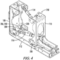
- the spacer 76B seen in Figs. 3 and 4 has four of the adjustable wear assemblies 200. Two are connected between the wear plate 112 and the front frame member 108, and two are connected between the wear plate 112 and the rear frame member 110. Portions of three of the adjustable fastener assemblies 200 are visible and identified in the perspective view of Fig. 4 .
- Fig. 5 is a left side elevation partly sectioned view of the lower left front corner portion of the spacer 76B of Fig. 4 .
- the front frame member 108 is seen to include a mounting flange 202 having a fastener opening 204 and a drive access opening 206 defined therein. More generally the openings 204 and 206 may be described as being defined at least in part by the mounting flange 202.
- the adjustable fastener assembly 200 may be located inside the spacer 76B of mold apparatus 24 between the front frame member 108 and the rear frame member 110 and above the wear plate 112.
- the adjustable fastener assembly 200 may include a threaded fastener 208 attached to the wear plate 112 and extending upward through the fastener opening 204 of the mounting flange 202.
- a top nut 210 may be attached to the threaded fastener 208 above the mounting flange 202.
- An adjusting nut 212 may be attached to the threaded fastener 208 below the mounting flange 202, such that the adjusting nut 212 is accessible from inside the mold apparatus 24 through the drive access opening 206.
- the wear plate 112 includes a lower mounting flange 218.
- the threaded fastener 208 is shown to be threadedly received in a lower threaded bore 220 of the lower mounting flange 218.
- the threaded fastener 208 is locked in place relative to the lower mounting flange 218 of the wear plate 112 with a bottom nut 214 threaded onto the threaded fastener 208.
- a washer 216 may be located between the bottom nut 214 and the bottom surface of the lower mounting flange 218.
- the threaded fastener 208 could be attached to the wear plate 212 by welding. Further alternatively, the threaded fastener could have an eye at its lower end and be attached to the wear plate 112 via a pin connection.
- the components of the adjustable fastener assembly 200 are best illustrated in the exploded view of Fig. 7 .
- the adjustable fastener assembly 200 further includes first and second spacer bushings 222 and 224 and a washer 226, located between the top nut 210 and the mounting flange 202.
- a lower washer 228 may be located between the mounting flange 202 and the adjusting nut 212.
- the adjusting nut 212 is disk shaped and includes a plurality of external recesses 230 configured as notches in an external periphery 232 of the adjusting nut 212.
- Each of the notches 230 is defined between two opposed substantially parallel notch sides such as 234 and 236.
- the adjustable fastener assembly 200 of Figs. 5 - 7 is designed for use with a manually powered adjusting nut drive 238 configured to extend downward through the drive access opening 206 to engage the adjusting nut 212 so that a position of the wear plate 112 below the mounting flange 202 of the front frame member 108 of spacer 76B is adjustable.
- the manually powered adjusting nut drive 238 includes a pivot guide 240 having a cylindrical bore 242 therethrough configured to be received over the threaded fastener 208 and more particularly to be closely received about the spacer bushings 222 and 224, so that the manually powered adjusting nut drive 238 may pivot about a longitudinal axis 244 of the threaded fastener 208.
- a handle 246 extends from the pivot guide 240, and a drive lug 248 extends downward from the handle 246.
- the drive access opening 206 may include an arc shaped portion 250 configured to receive the drive lug 248 and to allow the drive lug 248 to move in an arc 254 about the longitudinal axis 244 of the threaded fastener 208 to rotate the adjusting nut 212 relative to the threaded fastener 208.
- the arc shaped portion 250 may encompass an arc 254 in a range of from about 60 degrees to about 120 degrees
- the notches 230 of the adjusting nut 212 are configured to receive the drive lug 248.
- the drive lug 248 preferably includes two substantially parallel opposed driving sides such as 252 seen in Fig. 7 .
- a second parallel driving side is on the opposite side of the drive lug 248.
- the bore 242 of pivot guide 240 is placed over the guide bushings 224 and 226 which are closely received in the bore 242.
- the drive 238 is lowered until its drive lug 248 is received in one of the notches 230 of the adjusting nut 212.
- the drive 238 is manually rotated about axis 244 to rotate the adjusting nut 212 upon the threaded fastener 208 through some portion of the arc 254 to adjust the height of the wear plate 112 relative to the front spacer frame 108.
- the drive 238 may then be lifted and reengaged with another notch 230 to again rotate the adjusting nut through some portion of the available arc 254.
- the adjustable fastener assembly 200 is locked in place by tightening the top nut 210.
- the manually powered adjusting nut drive may be constructed with a ratchet between the drive lug and the handle as is shown in Figs. 13 and 14 .
- a side elevation view is shown of a modified manually powered adjusting nut drive designated by the number 400.
- the adjusting nut drive 400 includes a pivot guide 402 and a handle 404.
- the pivot guide 402 fits closely over the spacer bushings 222 and 224 in the same manner as the previously described embodiment.
- the handle 404 includes a downward extending protrusion 406 on which is mounted a drive lug 408 with a ratchet 410 between the drive lug 408 and the protrusion 406 of handle 404.
- the ratchet 410 includes a pivotal mounting 412 of the drive lug 408 on the handle 404, and a biasing spring 414 which can be adjusted in position to selectively bias the drive lug 408 in a selected rotational direction about the longitudinal axis 244 of the threaded fastener 208.
- adjustment switch 416 on the handle 404 can switch the direction of the ratchet 410 so that the adjusting nut drive 400 can either tighten or loosen the adjusting nut 212.
- Fig. 14 a schematic bottom view of the apparatus of Fig. 13 is shown, with the drive lug 408 engaged with the adjusting nut 212 in a position to loosen the adjusting nut 212.
- the drive access opening 206 includes both the arc shaped portion 250 and an at least partially circular portion 256 having a center 258 offset from the longitudinal axis 244 of the threaded fastener 208.
- the at least partially circular portion 256 of the drive access opening 206 is configured to receive an automatically powered adjusting nut drive 301 configured to extend downward through the at least partially circular portion 256 of drive access opening 206 to engage the adjusting nut 312 of an adjustable fastener assembly 300 so that a position of the wear plate 112 below the mounting flange 202 is adjustable.
- the construction of the adjustable fastener assembly 300 is substantially the same as the adjustable fastener assembly 200 except for the construction of the adjusting nut.
- the adjusting nut 312 is in the form of a gear.
- the other components of the adjustable fastener assemblies are identical and carry identical part numbers in the drawings.
- the automatically powered adjusting nut drive 301 includes a drive motor 302 and a drive shaft 304 extending downward from the drive motor 302 through the at least partially circular portion 256 of the drive access opening 206.
- a drive bushing 306 is received about the drive shaft 304 and configured to be closely received within the at least partially circular portion 256 of the drive access opening 206.
- a positioning flange 307 is located above the drive bushing 306 to limit the downward insertion of the drive shaft 304.
- a drive gear 308 is attached to the driveshaft 304 below the drive bushing 306 and configured to engage the adjusting nut 312 when the drive bushing 306 is received in the at least partially circular portion 256 of the drive access opening 206.
- the drive motor 302 may be part of a hand held tool assembly 320 having a handle 322 and battery pack 324. It is noted that the at least partially circular portion 256 of the drive access opening 206 does not have to be defined as a complete circle. The at least partially circular portion 256 may be defined as a complete circle, or as partial arc of a circle, or even as a series of engagement points lying upon a circle. It is only necessary that the at least partially circular portion 256 be configured so that it will closely receive the rotatable drive busing 306 and guide the same.
- the adjusting nut 312 is configured as a gear 312 have the external gear teeth 310.
- the external recesses of the adjusting nut 312 are configured as spaces 314 between the gear teeth 310.
- the gear teeth 310 of the adjusting nut 312 have an axial adjusting nut tooth height 316.
- the drive gear 308 has an axial drive gear tooth height 318 which is greater than the axial adjusting nut tooth height 316. This allows a range of location of the drive gear 308 in the axial direction while still maintaining engagement between the drive gear 308 and the gear teeth 310 of the adjusting nut 312.
- the adjusting nut When the drive gear 308 is engaged with the adjusting nut 312 the adjusting nut may be rotated to adjust the height of the wear plate 112.
- the drive access opening 206 is illustrated as having both the arc shaped portion 250 and the at least partially circular portion 256.
- the arc shaped portion 250 allows use of the adjustable fastener assemblies 200 with the manually powered adjusting nut drive 238.
- the at least partially circular portion 256 allows use of the adjustable fastener assemblies 300 with the automatically powered adjusting nut drive 301.
- the drive access opening 206 can be configured to have only the arc shaped portion 250 such as is seen for example in the embodiment of Fig. 4 .
- the drive access opening could be configured to have only the at least partially circular portion 256.
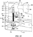
- FIG. 11 and 12 A modified embodiment of the adjustable fastener assembly and the automatically powered adjusting nut drive is shown in Figs. 11 and 12 .
- a circular guide opening is provided in a washer plate of the adjustable fastener assembly. This provides a more precise alignment of the drive gear with the adjusting nut, as compared to the embodiment of Figs. 8-10 .
- the adjustable fastener assembly includes a washer plate 500 received about the threaded fastener 208 between the mounting flange 202 and the adjusting nut 212.
- the washer plate 500 may replace the lower washer 228 of the embodiment of Figs. 5-10 .
- the washer plate 500 includes an eccentric portion 502 extending under the drive access opening 206.
- the eccentric portion 502 has a circular guide opening 504 defined therethrough.
- An ear 506 of the eccentric portion 502 includes a bolt hole 508 for an anchor bolt 510 (see Fig. 12 ) which anchors the washer plate 500 against rotation about the threaded fastener 208.
- the circular guide opening 504 may be concentrically located below the at least partially circular portion 256 of the drive access opening 206.
- the automatically powered adjusting nut drive 320 of Figs. 11 and 12 includes a modified drive gear 512, drive bushing 514 and positioning flange 516.
- the drive shaft 304 and attached components are inserted downwardly through the drive access opening 206 and the circular guide opening 504 until the drive gear 512 engages the teeth of the adjusting nut 312 and the drive bushing 514 is closely received in the circular guide opening 504 with the positioning flange 516 abutting a top surface of the washer plate 500.
- the close engagement of the drive bushing 514 with the circular guide opening 504 holds the drive gear 512 in engagement with the teeth of the adjusting nut 212.
- the guide opening 504 does not have to be completely circular, but only needs to be configured so that it will closely receive and guide the drive bushing 514.
- the mold apparatus has been illustrated as a removable segment of an adjustable width mold.
- the mold apparatus may be of the fixed width type of unitary construction or constructed of segments bolted together, and again there may be adjacent segments of the wear plate.
- the wear plates 51 of the sideform assemblies 52, 56 and the wear plates 43, 44 of the center portion 46 may be mounted on their respective frameworks using the same adjustable fastener assemblies 200, 300 described above.
- the left sideform assembly 52 may have its wear plate 51 attached to its sideform framework 53 using a plurality of the adjustable fastener assemblies 200, 300.
Landscapes
- Engineering & Computer Science (AREA)
- Architecture (AREA)
- Civil Engineering (AREA)
- Structural Engineering (AREA)
- General Engineering & Computer Science (AREA)
- Mechanical Engineering (AREA)
- Moulds, Cores, Or Mandrels (AREA)
- Moulds For Moulding Plastics Or The Like (AREA)
Applications Claiming Priority (1)
| Application Number | Priority Date | Filing Date | Title |
|---|---|---|---|
| US16/729,554 US11085154B2 (en) | 2019-12-30 | 2019-12-30 | Adjustable wear sole |
Publications (3)
| Publication Number | Publication Date |
|---|---|
| EP3845709A1 true EP3845709A1 (de) | 2021-07-07 |
| EP3845709C0 EP3845709C0 (de) | 2024-02-07 |
| EP3845709B1 EP3845709B1 (de) | 2024-02-07 |
Family
ID=74004070
Family Applications (1)
| Application Number | Title | Priority Date | Filing Date |
|---|---|---|---|
| EP20217864.6A Active EP3845709B1 (de) | 2019-12-30 | 2020-12-30 | Einstellbare verschleisssohle |
Country Status (3)
| Country | Link |
|---|---|
| US (1) | US11085154B2 (de) |
| EP (1) | EP3845709B1 (de) |
| CN (1) | CN113123196B (de) |
Cited By (3)
| Publication number | Priority date | Publication date | Assignee | Title |
|---|---|---|---|---|
| WO2023117639A1 (en) * | 2021-12-20 | 2023-06-29 | Wirtgen Gmbh | Slip form paving machine with a swelling sensor and method of controlling such slip form paving machine |
| EP4386141A1 (de) * | 2022-12-14 | 2024-06-19 | Wirtgen GmbH | Gleitschalungsfertiger und verfahren zur steuerung eines gleitschalungsfertigers |
| EP4386140A1 (de) * | 2022-12-14 | 2024-06-19 | Wirtgen GmbH | Gleitschalungsfertiger und verfahren zur steuerung eines gleitschalungsfertigers |
Families Citing this family (1)
| Publication number | Priority date | Publication date | Assignee | Title |
|---|---|---|---|---|
| US20240401286A1 (en) * | 2023-05-30 | 2024-12-05 | Caterpillar Paving Products Inc. | Paving machine including screed assembly with compression mechanisms |
Citations (5)
| Publication number | Priority date | Publication date | Assignee | Title |
|---|---|---|---|---|
| US3673930A (en) * | 1970-06-15 | 1972-07-04 | Schneider Simpson | Screed extension assembly for asphalt paving machines |
| US3970405A (en) * | 1974-05-03 | 1976-07-20 | Cmi Corporation | Slipform paving apparatus |
| US6273636B1 (en) * | 1999-10-08 | 2001-08-14 | Blaw-Knox Construction Equipment Corporation | Edge-forming device for a screed assembly |
| WO2002101150A1 (de) | 2001-06-13 | 2002-12-19 | Wirtgen Gmbh | Gleitschalungsfertiger |
| US7950874B2 (en) | 2009-04-16 | 2011-05-31 | Guntert & Zimmerman Const. Div., Inc. | Slipform paving machine with adjustable length paving kit |
Family Cites Families (12)
| Publication number | Priority date | Publication date | Assignee | Title |
|---|---|---|---|---|
| US3413901A (en) * | 1967-03-16 | 1968-12-03 | Ind Engineering Developments I | Apparatus and method for inserting a continuous and solid joint strip into plastic concrete |
| US3792133A (en) * | 1972-06-30 | 1974-02-12 | Aukerman A Co | Method for slip-forming walls of asymmetrical transverse cross section |
| DE2845465A1 (de) * | 1978-10-19 | 1980-04-30 | Hoes Maschf Klaus Gerd | Vorrichtung zum dosieren des baustoff-zuflusses unter eine breitenverstellbare strassenfertigerbohle |
| US7850395B1 (en) * | 2002-03-15 | 2010-12-14 | GOMACO Corporation a division of Godbersen Smith Construction Co. | Smoothness indicator analysis system |
| US6984089B1 (en) * | 2004-12-22 | 2006-01-10 | Power Curbers, Inc. | Adjustable-batter side plate for slip-form paver |
| CN101649598B (zh) * | 2009-09-22 | 2011-05-04 | 长安大学 | 具有热变形补偿性能的摊铺机熨平板 |
| CN102465485A (zh) * | 2010-11-04 | 2012-05-23 | 陕西中大机械集团有限责任公司 | 摊铺机熨平装置料楔引导机构 |
| DE102010051972A1 (de) * | 2010-11-19 | 2012-05-24 | Wirtgen Gmbh | Gleitschalungsfertiger |
| DE102013007061B4 (de) * | 2013-01-28 | 2021-09-02 | Bomag Gmbh | Höhenverstellvorrichtung für eine Ausfahrbohle eines Straßenfertigers sowie Straßenfertiger mit einer derartigen Höhenverstellvorrichtung |
| US9290893B2 (en) * | 2013-04-08 | 2016-03-22 | Advant-Edge Paving Equipment, LLC | Roadway paving system |
| CN206070317U (zh) * | 2016-09-26 | 2017-04-05 | 合肥佳恩特机械制造有限公司 | 双层宽度可调的熨平板 |
| US10844556B2 (en) * | 2019-03-21 | 2020-11-24 | Caterpillar Paving Products Inc. | Screed extension for a main screed frame of a paving machine |
-
2019
- 2019-12-30 US US16/729,554 patent/US11085154B2/en active Active
-
2020
- 2020-12-22 CN CN202011523676.0A patent/CN113123196B/zh active Active
- 2020-12-30 EP EP20217864.6A patent/EP3845709B1/de active Active
Patent Citations (6)
| Publication number | Priority date | Publication date | Assignee | Title |
|---|---|---|---|---|
| US3673930A (en) * | 1970-06-15 | 1972-07-04 | Schneider Simpson | Screed extension assembly for asphalt paving machines |
| US3970405A (en) * | 1974-05-03 | 1976-07-20 | Cmi Corporation | Slipform paving apparatus |
| US6273636B1 (en) * | 1999-10-08 | 2001-08-14 | Blaw-Knox Construction Equipment Corporation | Edge-forming device for a screed assembly |
| WO2002101150A1 (de) | 2001-06-13 | 2002-12-19 | Wirtgen Gmbh | Gleitschalungsfertiger |
| US6872028B2 (en) | 2001-06-13 | 2005-03-29 | Wirtgen Gmbh | Slip form paver |
| US7950874B2 (en) | 2009-04-16 | 2011-05-31 | Guntert & Zimmerman Const. Div., Inc. | Slipform paving machine with adjustable length paving kit |
Cited By (6)
| Publication number | Priority date | Publication date | Assignee | Title |
|---|---|---|---|---|
| WO2023117639A1 (en) * | 2021-12-20 | 2023-06-29 | Wirtgen Gmbh | Slip form paving machine with a swelling sensor and method of controlling such slip form paving machine |
| US12203226B2 (en) | 2021-12-20 | 2025-01-21 | Wirtgen Gmbh | Dowel bar inserter |
| EP4386141A1 (de) * | 2022-12-14 | 2024-06-19 | Wirtgen GmbH | Gleitschalungsfertiger und verfahren zur steuerung eines gleitschalungsfertigers |
| EP4386140A1 (de) * | 2022-12-14 | 2024-06-19 | Wirtgen GmbH | Gleitschalungsfertiger und verfahren zur steuerung eines gleitschalungsfertigers |
| US12473698B2 (en) | 2022-12-14 | 2025-11-18 | Wirtgen Gmbh | Roll control during slip form paving |
| US12601122B2 (en) | 2022-12-14 | 2026-04-14 | Wirtgen Gmbh | Adjustable string line sensors for slip form paving |
Also Published As
| Publication number | Publication date |
|---|---|
| EP3845709C0 (de) | 2024-02-07 |
| US20210198852A1 (en) | 2021-07-01 |
| EP3845709B1 (de) | 2024-02-07 |
| CN113123196B (zh) | 2022-10-14 |
| CN113123196A (zh) | 2021-07-16 |
| US11085154B2 (en) | 2021-08-10 |
Similar Documents
| Publication | Publication Date | Title |
|---|---|---|
| EP3845709B1 (de) | Einstellbare verschleisssohle | |
| DE68921323T2 (de) | Decken-Fertigungsmaschine und Verfahren. | |
| US6273636B1 (en) | Edge-forming device for a screed assembly | |
| US11162233B2 (en) | Adjustable width mold | |
| US9751236B2 (en) | Height adjustable concrete form assembly | |
| DE69112822T2 (de) | Gesteinsfräsradanordnung. | |
| DE102015016678A1 (de) | Verfahren zum Anbau einer Fräseinheit einer Bodenfräsmaschine und Bodenfräsmaschine mit einer ab- und anbaubaren Fräseinheit | |
| DE4116712C2 (de) | Maschine mit Gleitschalung zum Einbau von Material für z.B. Bordsteine und Rinnen | |
| CN112921760B (zh) | 宽度可调模具装置 | |
| DE202013004195U1 (de) | Verlängerungsbefestigungssystem zum Befestigen einer Glättbodenverlängerung an einer Glättbohle | |
| EP3208384B1 (de) | Schlitzwandvorrichtung und verfahren zum erstellen von schlitzen im boden | |
| US6174105B1 (en) | Strike-off device for a paving screed | |
| DE3608893C2 (de) | Planiereinrichtung | |
| US8016045B2 (en) | Method and apparatus for distributing particulate matter | |
| US10577758B2 (en) | Road paver with quick coupling apparatus for the transverse distribution device, and method | |
| DE68918516T2 (de) | Sperrvorrichtung für Drehreaktionskraft. | |
| DE1784634A1 (de) | Geraet zur Verdichtung von Strassenbelaegen | |
| US11365522B2 (en) | Grading system | |
| DE3627719C1 (de) | Bagger,insbesondere selbstfahrender hydraulischer Universal-Kleinbagger | |
| DE202020102659U1 (de) | Schalungsstütze, Schalungselement und Schalungssystem für den Gleisbau fester Fahrbahnen | |
| DE3036234A1 (de) | Vorrichtung zur nivellierung einer betonbelagsoberflaeche und verfahren zu ihrem betrieb | |
| CN222758981U (zh) | 一种可调节刨平角度的平地刨 | |
| DE3815640A1 (de) | Verfahrbarer fugenschneider | |
| CN114960306B (zh) | 一种路基支护结构 | |
| DE102018113955B4 (de) | Baufahrzeug zur Herstellung von Rammpfählen |
Legal Events
| Date | Code | Title | Description |
|---|---|---|---|
| PUAI | Public reference made under article 153(3) epc to a published international application that has entered the european phase |
Free format text: ORIGINAL CODE: 0009012 |
|
| STAA | Information on the status of an ep patent application or granted ep patent |
Free format text: STATUS: THE APPLICATION HAS BEEN PUBLISHED |
|
| AK | Designated contracting states |
Kind code of ref document: A1 Designated state(s): AL AT BE BG CH CY CZ DE DK EE ES FI FR GB GR HR HU IE IS IT LI LT LU LV MC MK MT NL NO PL PT RO RS SE SI SK SM TR |
|
| STAA | Information on the status of an ep patent application or granted ep patent |
Free format text: STATUS: REQUEST FOR EXAMINATION WAS MADE |
|
| 17P | Request for examination filed |
Effective date: 20220107 |
|
| RBV | Designated contracting states (corrected) |
Designated state(s): AL AT BE BG CH CY CZ DE DK EE ES FI FR GB GR HR HU IE IS IT LI LT LU LV MC MK MT NL NO PL PT RO RS SE SI SK SM TR |
|
| P01 | Opt-out of the competence of the unified patent court (upc) registered |
Effective date: 20230527 |
|
| GRAP | Despatch of communication of intention to grant a patent |
Free format text: ORIGINAL CODE: EPIDOSNIGR1 |
|
| STAA | Information on the status of an ep patent application or granted ep patent |
Free format text: STATUS: GRANT OF PATENT IS INTENDED |
|
| INTG | Intention to grant announced |
Effective date: 20230811 |
|
| GRAS | Grant fee paid |
Free format text: ORIGINAL CODE: EPIDOSNIGR3 |
|
| GRAA | (expected) grant |
Free format text: ORIGINAL CODE: 0009210 |
|
| STAA | Information on the status of an ep patent application or granted ep patent |
Free format text: STATUS: THE PATENT HAS BEEN GRANTED |
|
| AK | Designated contracting states |
Kind code of ref document: B1 Designated state(s): AL AT BE BG CH CY CZ DE DK EE ES FI FR GB GR HR HU IE IS IT LI LT LU LV MC MK MT NL NO PL PT RO RS SE SI SK SM TR |
|
| REG | Reference to a national code |
Ref country code: GB Ref legal event code: FG4D |
|
| REG | Reference to a national code |
Ref country code: CH Ref legal event code: EP |
|
| REG | Reference to a national code |
Ref country code: DE Ref legal event code: R096 Ref document number: 602020025301 Country of ref document: DE |
|
| REG | Reference to a national code |
Ref country code: IE Ref legal event code: FG4D |
|
| U01 | Request for unitary effect filed |
Effective date: 20240307 |
|
| U07 | Unitary effect registered |
Designated state(s): AT BE BG DE DK EE FI FR IT LT LU LV MT NL PT SE SI Effective date: 20240314 |
|
| P04 | Withdrawal of opt-out of the competence of the unified patent court (upc) registered |
Effective date: 20240412 |
|
| PG25 | Lapsed in a contracting state [announced via postgrant information from national office to epo] |
Ref country code: IS Free format text: LAPSE BECAUSE OF FAILURE TO SUBMIT A TRANSLATION OF THE DESCRIPTION OR TO PAY THE FEE WITHIN THE PRESCRIBED TIME-LIMIT Effective date: 20240607 |
|
| PG25 | Lapsed in a contracting state [announced via postgrant information from national office to epo] |
Ref country code: GR Free format text: LAPSE BECAUSE OF FAILURE TO SUBMIT A TRANSLATION OF THE DESCRIPTION OR TO PAY THE FEE WITHIN THE PRESCRIBED TIME-LIMIT Effective date: 20240508 |
|
| PG25 | Lapsed in a contracting state [announced via postgrant information from national office to epo] |
Ref country code: RS Free format text: LAPSE BECAUSE OF FAILURE TO SUBMIT A TRANSLATION OF THE DESCRIPTION OR TO PAY THE FEE WITHIN THE PRESCRIBED TIME-LIMIT Effective date: 20240507 Ref country code: HR Free format text: LAPSE BECAUSE OF FAILURE TO SUBMIT A TRANSLATION OF THE DESCRIPTION OR TO PAY THE FEE WITHIN THE PRESCRIBED TIME-LIMIT Effective date: 20240207 |
|
| PG25 | Lapsed in a contracting state [announced via postgrant information from national office to epo] |
Ref country code: ES Free format text: LAPSE BECAUSE OF FAILURE TO SUBMIT A TRANSLATION OF THE DESCRIPTION OR TO PAY THE FEE WITHIN THE PRESCRIBED TIME-LIMIT Effective date: 20240207 |
|
| PG25 | Lapsed in a contracting state [announced via postgrant information from national office to epo] |
Ref country code: RS Free format text: LAPSE BECAUSE OF FAILURE TO SUBMIT A TRANSLATION OF THE DESCRIPTION OR TO PAY THE FEE WITHIN THE PRESCRIBED TIME-LIMIT Effective date: 20240507 Ref country code: NO Free format text: LAPSE BECAUSE OF FAILURE TO SUBMIT A TRANSLATION OF THE DESCRIPTION OR TO PAY THE FEE WITHIN THE PRESCRIBED TIME-LIMIT Effective date: 20240507 Ref country code: IS Free format text: LAPSE BECAUSE OF FAILURE TO SUBMIT A TRANSLATION OF THE DESCRIPTION OR TO PAY THE FEE WITHIN THE PRESCRIBED TIME-LIMIT Effective date: 20240607 Ref country code: HR Free format text: LAPSE BECAUSE OF FAILURE TO SUBMIT A TRANSLATION OF THE DESCRIPTION OR TO PAY THE FEE WITHIN THE PRESCRIBED TIME-LIMIT Effective date: 20240207 Ref country code: GR Free format text: LAPSE BECAUSE OF FAILURE TO SUBMIT A TRANSLATION OF THE DESCRIPTION OR TO PAY THE FEE WITHIN THE PRESCRIBED TIME-LIMIT Effective date: 20240508 Ref country code: ES Free format text: LAPSE BECAUSE OF FAILURE TO SUBMIT A TRANSLATION OF THE DESCRIPTION OR TO PAY THE FEE WITHIN THE PRESCRIBED TIME-LIMIT Effective date: 20240207 |
|
| PG25 | Lapsed in a contracting state [announced via postgrant information from national office to epo] |
Ref country code: PL Free format text: LAPSE BECAUSE OF FAILURE TO SUBMIT A TRANSLATION OF THE DESCRIPTION OR TO PAY THE FEE WITHIN THE PRESCRIBED TIME-LIMIT Effective date: 20240207 |
|
| PG25 | Lapsed in a contracting state [announced via postgrant information from national office to epo] |
Ref country code: PL Free format text: LAPSE BECAUSE OF FAILURE TO SUBMIT A TRANSLATION OF THE DESCRIPTION OR TO PAY THE FEE WITHIN THE PRESCRIBED TIME-LIMIT Effective date: 20240207 |
|
| PG25 | Lapsed in a contracting state [announced via postgrant information from national office to epo] |
Ref country code: SM Free format text: LAPSE BECAUSE OF FAILURE TO SUBMIT A TRANSLATION OF THE DESCRIPTION OR TO PAY THE FEE WITHIN THE PRESCRIBED TIME-LIMIT Effective date: 20240207 |
|
| PG25 | Lapsed in a contracting state [announced via postgrant information from national office to epo] |
Ref country code: CZ Free format text: LAPSE BECAUSE OF FAILURE TO SUBMIT A TRANSLATION OF THE DESCRIPTION OR TO PAY THE FEE WITHIN THE PRESCRIBED TIME-LIMIT Effective date: 20240207 |
|
| PG25 | Lapsed in a contracting state [announced via postgrant information from national office to epo] |
Ref country code: SK Free format text: LAPSE BECAUSE OF FAILURE TO SUBMIT A TRANSLATION OF THE DESCRIPTION OR TO PAY THE FEE WITHIN THE PRESCRIBED TIME-LIMIT Effective date: 20240207 |
|
| PG25 | Lapsed in a contracting state [announced via postgrant information from national office to epo] |
Ref country code: SM Free format text: LAPSE BECAUSE OF FAILURE TO SUBMIT A TRANSLATION OF THE DESCRIPTION OR TO PAY THE FEE WITHIN THE PRESCRIBED TIME-LIMIT Effective date: 20240207 Ref country code: SK Free format text: LAPSE BECAUSE OF FAILURE TO SUBMIT A TRANSLATION OF THE DESCRIPTION OR TO PAY THE FEE WITHIN THE PRESCRIBED TIME-LIMIT Effective date: 20240207 Ref country code: RO Free format text: LAPSE BECAUSE OF FAILURE TO SUBMIT A TRANSLATION OF THE DESCRIPTION OR TO PAY THE FEE WITHIN THE PRESCRIBED TIME-LIMIT Effective date: 20240207 Ref country code: CZ Free format text: LAPSE BECAUSE OF FAILURE TO SUBMIT A TRANSLATION OF THE DESCRIPTION OR TO PAY THE FEE WITHIN THE PRESCRIBED TIME-LIMIT Effective date: 20240207 |
|
| REG | Reference to a national code |
Ref country code: DE Ref legal event code: R097 Ref document number: 602020025301 Country of ref document: DE |
|
| PLBE | No opposition filed within time limit |
Free format text: ORIGINAL CODE: 0009261 |
|
| STAA | Information on the status of an ep patent application or granted ep patent |
Free format text: STATUS: NO OPPOSITION FILED WITHIN TIME LIMIT |
|
| 26N | No opposition filed |
Effective date: 20241108 |
|
| U20 | Renewal fee for the european patent with unitary effect paid |
Year of fee payment: 5 Effective date: 20241219 |
|
| PG25 | Lapsed in a contracting state [announced via postgrant information from national office to epo] |
Ref country code: MC Free format text: LAPSE BECAUSE OF FAILURE TO SUBMIT A TRANSLATION OF THE DESCRIPTION OR TO PAY THE FEE WITHIN THE PRESCRIBED TIME-LIMIT Effective date: 20240207 |
|
| REG | Reference to a national code |
Ref country code: CH Ref legal event code: PL |
|
| GBPC | Gb: european patent ceased through non-payment of renewal fee |
Effective date: 20241230 |
|
| PG25 | Lapsed in a contracting state [announced via postgrant information from national office to epo] |
Ref country code: GB Free format text: LAPSE BECAUSE OF NON-PAYMENT OF DUE FEES Effective date: 20241230 |
|
| PG25 | Lapsed in a contracting state [announced via postgrant information from national office to epo] |
Ref country code: CH Free format text: LAPSE BECAUSE OF NON-PAYMENT OF DUE FEES Effective date: 20241231 |
|
| PG25 | Lapsed in a contracting state [announced via postgrant information from national office to epo] |
Ref country code: IE Free format text: LAPSE BECAUSE OF NON-PAYMENT OF DUE FEES Effective date: 20241230 |
|
| U20 | Renewal fee for the european patent with unitary effect paid |
Year of fee payment: 6 Effective date: 20251222 |