EP3845722A1 - Bodenseitiger wandabschluss - Google Patents
Bodenseitiger wandabschluss Download PDFInfo
- Publication number
- EP3845722A1 EP3845722A1 EP20216527.0A EP20216527A EP3845722A1 EP 3845722 A1 EP3845722 A1 EP 3845722A1 EP 20216527 A EP20216527 A EP 20216527A EP 3845722 A1 EP3845722 A1 EP 3845722A1
- Authority
- EP
- European Patent Office
- Prior art keywords
- wall
- plaster
- leg
- cover profile
- strip
- Prior art date
- Legal status (The legal status is an assumption and is not a legal conclusion. Google has not performed a legal analysis and makes no representation as to the accuracy of the status listed.)
- Granted
Links
Images
Classifications
-
- E—FIXED CONSTRUCTIONS
- E04—BUILDING
- E04F—FINISHING WORK ON BUILDINGS, e.g. STAIRS, FLOORS
- E04F19/00—Other details of constructional parts for finishing work on buildings
- E04F19/02—Borders; Finishing strips, e.g. beadings; Light coves
- E04F19/04—Borders; Finishing strips, e.g. beadings; Light coves for use between floor or ceiling and wall, e.g. skirtings
- E04F19/0459—Borders; Finishing strips, e.g. beadings; Light coves for use between floor or ceiling and wall, e.g. skirtings characterised by the fixing method
- E04F19/0463—Plinths fixed by snap-action in a direction perpendicular to the wall
-
- E—FIXED CONSTRUCTIONS
- E04—BUILDING
- E04F—FINISHING WORK ON BUILDINGS, e.g. STAIRS, FLOORS
- E04F19/00—Other details of constructional parts for finishing work on buildings
- E04F19/02—Borders; Finishing strips, e.g. beadings; Light coves
- E04F19/04—Borders; Finishing strips, e.g. beadings; Light coves for use between floor or ceiling and wall, e.g. skirtings
- E04F19/0481—Skirtings or crown mouldings with a separate cladding strip
-
- E—FIXED CONSTRUCTIONS
- E04—BUILDING
- E04F—FINISHING WORK ON BUILDINGS, e.g. STAIRS, FLOORS
- E04F19/00—Other details of constructional parts for finishing work on buildings
- E04F19/02—Borders; Finishing strips, e.g. beadings; Light coves
- E04F19/04—Borders; Finishing strips, e.g. beadings; Light coves for use between floor or ceiling and wall, e.g. skirtings
- E04F19/049—Plinths specially adapted for joining wall coverings to floor surfaces
Definitions
- the invention relates to a floor-side wall termination with a plaster strip, which has a wall leg that can be fastened to a wall and a plaster connection leg protruding from the wall leg, and with a cover profile that can be connected to the plaster strip.
- the invention is therefore based on the object of designing a floor-side wall closure with a plaster strip in such a way that simple fastening of the cover profile is ensured while compensating for the usual tolerances in relation to a straight wall course.
- the invention solves the problem in that the wall leg of the plaster strip forms an undercut receiving groove running in the longitudinal direction of the plaster strip for holders distributed over the length of the plaster strip for fastening the cover profile Has undercuts of the receiving groove engaging resilient latching tongues and on the other hand undercut latching recesses into which the resilient latching webs of the cover profile resting against the holders engage.
- the holders engaging in a groove in the wall leg of the plaster strip represent an advantageous prerequisite for cable routing behind the cover profile.
- the holders only need to form a guide channel for cables protruding into the groove in the plaster strip.
- the guide troughs can have a holding leg which protrudes from the lower, bottom trough wall and leaves an insertion gap to the upper trough wall. The cables can be inserted into the guide channel of the holder via the opening gap that has been left free.
- the cover profile can have a sealing lip directed towards the floor along the lower, floor-side longitudinal edge.
- the cover profile can be flush with the plaster connection leg with its upper longitudinal edge.
- Such a design of the cover profile is an advantageous prerequisite for the arrangement of a light source strip when the light source strip is arranged on the underside of the plaster connection leg and the longitudinal edge section of the cover profile angled against the wall leg of the plaster strip is used as a reflector for the light source strip.
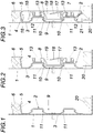
- a wall termination according to the invention comprises a plaster strip 2 which is fastened to the wall 1 and which has a wall leg 3 and a plaster connection leg 4 protruding from the wall leg 3.
- the plaster connection leg 4 forms a pull-off edge 5 for the plaster 6 applied to the wall 1.
- holders 8 are used, which engage in an undercut receiving groove 9 of the wall leg 3 with mutual spacing in the longitudinal direction of the plaster strip 2, the holder 8 being provided with resilient locking tongues 10 to secure the position, which the undercuts 11 of the Engage behind receiving groove 9, as is the case in particular Fig. 2 can be taken.
- the cover profile 7 has resilient locking webs 12 for its fastening, which snap into undercut locking recesses 13 of the holder 8 and then fix the cover profile 7 in contact with the holders 8.
- the cover profile 7 In the assembled position after Fig. 3 closes the cover profile 7 with its upper longitudinal edge 14 flush with the plaster connection leg 4. As indicated by dash-dotted lines, however, the cover profile 7 can also have a longitudinal edge section 15 angled against the wall leg 3 of the plaster strip 2, which forms a reflector for a lamp strip 16 provided on the plaster connection leg 4.
- the can in the Receiving groove 9 engaging part of the holder 8 can advantageously be used as a guide channel 17 for cables.
- the holders 8 can have a retaining leg 18 which protrudes from the channel wall at the bottom and which leaves an insertion gap 19 towards the upper channel wall.
- cover profile 7 can carry a sealing lip 21 directed towards the floor 20 along the lower, floor-side longitudinal edge.
Landscapes
- Engineering & Computer Science (AREA)
- Architecture (AREA)
- Civil Engineering (AREA)
- Structural Engineering (AREA)
- Floor Finish (AREA)
- Finishing Walls (AREA)
Abstract
Description
- Die Erfindung bezieht sich auf einen bodenseitigen Wandabschluss mit einer Putzleiste, die einen an einer Wand befestigbaren Wandschenkel und einen vom Wandschenkel abstehenden Putzanschlussschenkel aufweist, und mit einem mit der Putzleiste verbindbaren Abdeckprofil.
- Zur Ausbildung eines sockelartigen Wandabschlusses an einem Balkonboden ist es bekannt (
DE 295 15 156 U1 ), eine Putzleiste vorzusehen, die einen an der Wand anschraubbaren Wandschenkel und einen vom Wandschenkel abstehenden Putzanschlussschenkel bildet. Der Putzanschlussschenkel ist dabei unter Ausbildung eines Befestigungshakens gegen den Wandschenkel zurückgebogen, sodass auf diesen Befestigungshaken sowie auf einen hakenförmig aufgebogenen unteren Randsteg des Wandschenkels ein Abdeckprofil aufgesteckt werden kann, das zur Anpassung an unterschiedlich dicke Bodenbeläge aus zwei Profilschienen zusammengesetzt ist, von denen die auf der Putzleiste befestigte Profilschiene die gegen den Bodenbelag vorstehende Profilschiene der Höhe nach verstellbar aufnimmt. Abgesehen von der aufwendigen Konstruktion dieses bekannten Wandabschlusses ist es als nachteilig anzusehen, dass das Abdeckprofil auf hakenartigen Längsrandabschnitten der Putzleiste aufgesteckt werden muss, was bei Abweichungen von einem geraden Wandverlauf zu Befestigungsschwierigkeiten führt. - Bei ähnlichen Wandabschlüssen mit einer an der Wand befestigbaren Putzleiste, die Befestigungshaken zum Einhängen des mit Gegenhaken versehenen Abdeckprofils aufweist (
AT 516 533 A1 EP 2 090717 A1 ,US 2 203 119 A ) ergibt sich aufgrund des Umstands, dass das Abdeckprofil nicht in seiner Höhe verstellbar ist, der zusätzliche Nachteil, dass bei einem bündigen Anschluss des Abdeckprofils an die Putzleiste zwischen dem Putzanschlussschenkel und dem Abdeckprofil ein der Einhängetiefe der Gegenhaken in die Befestigungshaken entsprechender Abstand zur Montage des Abdeckprofils vorhanden sein muss. - Der Erfindung liegt somit die Aufgabe zugrunde, einen bodenseitigen Wandabschluss mit einer Putzleiste so auszugestalten, dass eine einfache Befestigung des Abdeckprofils unter einem Ausgleich üblicher Toleranzen in Bezug auf einen geraden Wandverlauf sichergestellt wird.
- Ausgehend von einem bodenseitigen Wandabschluss der eingangs geschilderten Art löst die Erfindung die gestellte Aufgabe dadurch, dass der Wandschenkel der Putzleiste eine in Längsrichtung der Putzleiste verlaufende, hinterschnittene Aufnahmenut für über die Länge der Putzleiste verteilte Halter zur Befestigung des Abdeckprofils bildet, dass die Halter einerseits die Hinterschneidungen der Aufnahmenut hintergreifende, federnde Rastzungen und anderseits hinterschnittene Rastausnehmungen aufweist, in die federnde Raststege des an den Haltern anliegenden Abdeckprofils eingreifen.
- Durch das Vorsehen von gesonderten Haltern für das Abdeckprofil, die über die Länge der Putzleiste verteilt und mit der Putzleiste schnappverschlussartig verbunden werden, können übliche Abweichungen von einem geraden Wandverlauf ohne zusätzlichen Konstruktionsaufwand berücksichtigt werden, weil der Putzleistenverlauf zwischen den mit beliebigem gegenseitigen Abstand auf der Putzleiste befestigbaren Haltern für die Befestigung des Abdeckprofils keine Rolle spielt. Dazu kommt, dass durch die federnde Verrastung einerseits zwischen der Putzleiste und den Haltern und anderseits zwischen den Haltern und dem Abdeckprofil ein zusätzlicher Toleranzausgleich ermöglicht wird, sodass eine einfache, von Abweichungen des geraden Wandverlaufs weitgehend unabhängige Befestigung des Abdeckprofils gewährleistet wird. Es brauchen ja lediglich die Halter in die Aufnahmenut des Wandschenkels der an der Wand befestigten Putzleiste unter einem Einrasten der federnden Rastzungen in die Hinterschneidungen der Aufnahmenut eingesetzt zu werden, bevor das Abdeckprofil mit den Haltern verbunden wird, indem die federnden Raststege des Abdeckprofils in die hinterschnittenen Rastausnehmungen der Halter eingedrückt werden. Mithilfe der in die hinterschnittenen Rastausnehmungen der Halter eingreifenden Raststege wird das Abdeckprofil dann ausgerichtet in Anlage an den Haltern gehalten.
- Die in eine Aufnahmenut des Wandschenkels der Putzleiste eingreifenden Halter stellen eine vorteilhafte Voraussetzung für eine Kabelführung hinter dem Abdeckprofil dar. Zu diesem Zweck brauchen die Halter ja lediglich eine in die Aufnahmenut der Putzleiste ragende Führungsrinne für Kabel zu bilden. Zur Lagesicherung der Kabel in der Führungsrinne der Halter können die Führungsrinnen einen von der unteren bodenseitigen Rinnenwand aufragenden, zur oberen Rinnenwand einen Einführspalt freilassenden Halteschenkel aufweisen. Die Kabel können über den freigelassenen Einführspalt in die Führungsrinne der Halter eingelegt werden.
- Um einen dichten Bodenanschluss zu ermöglichen, ohne eine Höhenverstellung für das Abdeckprofil vorsehen zu müssen, kann das Abdeckprofil entlang des unteren, bodenseitigen Längsrands eine gegen den Boden gerichtete Dichtlippe aufweisen.
- Im Bereich des Putzanschlussschenkels der Putzleiste kann das Abdeckprofil mit seinem oberen Längsrand bündig an den Putzanschlussschenkel anschließen. Es ist aber auch möglich, das Abdeckprofil mit einem gegen den Wandschenkel der Putzleiste abgewinkelten, oberen Längsrandabschnitt auszubilden, sodass sich eine Art Schattenfuge ergibt. Eine solche Ausbildung des Abdeckprofils stellt eine vorteilhafte Voraussetzung für die Anordnung eines Leuchtmittelbandes dar, wenn das Leuchtmittelband auf der Unterseite des Putzanschlussschenkels angeordnet wird und der gegen den Wandschenkel der Putzleiste abgewinkelte Längsrandabschnitt des Abdeckprofils als Reflektor für das Leuchtmittelband genützt wird.
- In der Zeichnung ist der Erfindungsgegenstand beispielsweise dargestellt. Es zeigen
- Fig. 1
- eine an einer verputzten Wand befestigte Putzleiste eines erfindungsgemäßen bodenseitigen Wandabschlusses in einem Querschnitt,
- Fig. 2
- die Putzleiste nach der
Fig. 1 mit einem eingesetzten Halter zur Befestigung eines Abdeckprofils und - Fig. 3
- den fertiggestellten Wandabschluss mit einem Abdeckprofil ebenfalls im Querschnitt.
- Ein erfindungsgemäßer Wandabschluss umfasst eine an der Wand 1 befestigte Putzleiste 2, die einen Wandschenkel 3 und einen vom Wandschenkel 3 abstehenden Putzanschlussschenkel 4 aufweist. Der Putzanschlussschenkel 4 bildet eine Abziehkante 5 für den auf der Wand 1 aufgebrachten Putz 6.
- Zur Befestigung eines Abdeckprofils 7 für die Putzleiste 2 dienen Halter 8, die in eine hinterschnittene Aufnahmenut 9 des Wandschenkels 3 mit gegenseitigem Abstand in Längsrichtung der Putzleiste 2 eingreifen, wobei die Halter 8 zur Lagesicherung mit federnden Rastzungen 10 versehen sind, die die Hinterschneidungen 11 der Aufnahmenut 9 hintergreifen, wie dies insbesondere der
Fig. 2 entnommen werden kann. - In ähnlicher Art weist das Abdeckprofil 7 zu seiner Befestigung federnde Raststege 12 auf, die in hinterschnittene Rastausnehmungen 13 der Halter 8 einrasten und dann das Abdeckprofil 7 in Anlage an den Haltern 8 festlegen.
- In der montierten Stellung nach
Fig. 3 schließt das Abdeckprofil 7 mit seinem oberen Längsrand 14 bündig an den Putzanschlussschenkel 4 an. Wie strichpunktiert angedeutet ist, kann das Abdeckprofil 7 aber auch einen gegen den Wandschenkel 3 der Putzleiste 2 abgewinkelten Längsrandabschnitt 15 aufweisen, der einen Reflektor für ein am Putzanschlussschenkel 4 vorgesehenes Leuchtmittelband 16 bildet. - Da für die Aufnahme der Halter 8 im Wandschenkel 3 der Putzleiste 2 eine Aufnahmenut 9 vorgesehen ist, in die die Halter eingreifen, kann der in die Aufnahmenut 9 eingreifende Teil der Halter 8 vorteilhaft als Führungsrinne 17 für Kabel genützt werden. Zur Lagesicherung der Kabel in den Führungsrinnen 17 können die Halter 8 einen von der bodenseigen Rinnenwand aufragenden Halteschenkel 18 aufweisen, der zur oberen Rinnenwand hin einen Einführspalt 19 freilässt.
- Wie der
Fig. 3 außerdem entnommen werden kann, kann das Abdeckprofil 7 entlang des unteren, bodenseitigen Längsrands eine gegen den Boden 20 gerichtete Dichtlippe 21 tragen.
Claims (6)
- Bodenseitiger Wandabschluss mit einer Putzleiste (2), die einen an einer Wand (1) befestigbaren Wandschenkel (3) und einen vom Wandschenkel (3) abstehenden Putzanschlussschenkel (4) aufweist, und mit einem mit der Putzleiste (2) verbindbaren Abdeckprofil (7), dadurch gekennzeichnet, dass der Wandschenkel (3) der Putzleiste (2) eine in Längsrichtung der Putzleiste (2) verlaufende, hinterschnittene Aufnahmenut (9) für über die Länge der Putzleiste (2) verteilte Halter (8) zur Befestigung des Abdeckprofils (7) bildet, dass die Halter (8) einerseits die Hinterschneidungen (11) der Aufnahmenut (9) hintergreifende, federnde Rastzungen (10) und anderseits hinterschnittene Rastausnehmungen (13) aufweist, in die federnde Raststege (12) des an den Haltern (8) anliegenden Abdeckprofils (7) eingreifen.
- Bodenseitiger Wandabschluss nach Anspruch 1, dadurch gekennzeichnet, dass die Halter (8) eine in die Aufnahmenut (9) des Wandschenkels (3) der Putzleiste (2) ragende Führungsrinne (17) für Kabel bilden.
- Bodenseitiger Wandabschluss nach Anspruch 2, dadurch gekennzeichnet, dass die Führungsrinne (17) der Halter (8) einen von der unteren bodenseitigen Rinnenwand aufragenden, zur oberen Rinnenwand einen Einführspalt (19) freilassenden Halteschenkel (18) aufweist.
- Bodenseitiger Wandabschluss nach einem der Ansprüche 1 bis 3, dadurch gekennzeichnet, dass das Abdeckprofil (7) entlang des unteren, bodenseitigen Längsrands eine gegen den Boden (20) gerichtete Dichtlippe (21) aufweist.
- Bodenseitiger Wandabschluss nach einem der Ansprüche 1 bis 4, dadurch gekennzeichnet, dass das Abdeckprofil (7) mit seinem oberen Längsrand bündig an den Putzanschlussschenkel (4) anschließt.
- Bodenseitiger Wandabschluss nach einem der Ansprüche 1 bis 4, dadurch gekennzeichnet, dass das Abdeckprofil (7) einen gegen den Wandschenkel (3) der Putzleiste (2) abgewinkelten, oberen Längsrandabschnitt 15) aufweist, der einen Reflektor für ein am Putzanschlussschenkel (4) vorgesehenes Leuchtmittelband (16) bildet.
Applications Claiming Priority (1)
| Application Number | Priority Date | Filing Date | Title |
|---|---|---|---|
| ATA50001/2020A AT523074B1 (de) | 2020-01-02 | 2020-01-02 | Bodenseitiger Wandabschluss |
Publications (2)
| Publication Number | Publication Date |
|---|---|
| EP3845722A1 true EP3845722A1 (de) | 2021-07-07 |
| EP3845722B1 EP3845722B1 (de) | 2022-09-07 |
Family
ID=73856833
Family Applications (1)
| Application Number | Title | Priority Date | Filing Date |
|---|---|---|---|
| EP20216527.0A Active EP3845722B1 (de) | 2020-01-02 | 2020-12-22 | Bodenseitiger wandabschluss |
Country Status (4)
| Country | Link |
|---|---|
| EP (1) | EP3845722B1 (de) |
| AT (1) | AT523074B1 (de) |
| ES (1) | ES2928941T3 (de) |
| PL (1) | PL3845722T3 (de) |
Citations (6)
| Publication number | Priority date | Publication date | Assignee | Title |
|---|---|---|---|---|
| US2203119A (en) | 1937-12-09 | 1940-06-04 | Milcor Steel Company | Wall trim |
| DE1946161U (de) * | 1966-05-26 | 1966-09-15 | Alexander Josek | Fussboden- und putzleiste. |
| DE29515156U1 (de) | 1995-09-22 | 1995-11-30 | Schlüter-Systems GmbH, 58640 Iserlohn | Vorrichtung zur Ausbildung eines sockelartigen Wandanschlusses an einem Boden |
| GB2413134A (en) * | 2001-03-09 | 2005-10-19 | Ultraframe Uk Ltd | Conservatory trim strip |
| EP2090717A1 (de) | 2008-02-18 | 2009-08-19 | Natural Faber, S.L. | Basiselement mit einem Verschlusselement und Verfahren für Installation auf einer Verkleidungswand |
| AT516533A1 (de) | 2014-11-28 | 2016-06-15 | Stia - Holzindustrie Ges M B H | Leisten-Montagebausatz |
-
2020
- 2020-01-02 AT ATA50001/2020A patent/AT523074B1/de active
- 2020-12-22 ES ES20216527T patent/ES2928941T3/es active Active
- 2020-12-22 PL PL20216527.0T patent/PL3845722T3/pl unknown
- 2020-12-22 EP EP20216527.0A patent/EP3845722B1/de active Active
Patent Citations (6)
| Publication number | Priority date | Publication date | Assignee | Title |
|---|---|---|---|---|
| US2203119A (en) | 1937-12-09 | 1940-06-04 | Milcor Steel Company | Wall trim |
| DE1946161U (de) * | 1966-05-26 | 1966-09-15 | Alexander Josek | Fussboden- und putzleiste. |
| DE29515156U1 (de) | 1995-09-22 | 1995-11-30 | Schlüter-Systems GmbH, 58640 Iserlohn | Vorrichtung zur Ausbildung eines sockelartigen Wandanschlusses an einem Boden |
| GB2413134A (en) * | 2001-03-09 | 2005-10-19 | Ultraframe Uk Ltd | Conservatory trim strip |
| EP2090717A1 (de) | 2008-02-18 | 2009-08-19 | Natural Faber, S.L. | Basiselement mit einem Verschlusselement und Verfahren für Installation auf einer Verkleidungswand |
| AT516533A1 (de) | 2014-11-28 | 2016-06-15 | Stia - Holzindustrie Ges M B H | Leisten-Montagebausatz |
Also Published As
| Publication number | Publication date |
|---|---|
| AT523074A4 (de) | 2021-05-15 |
| AT523074B1 (de) | 2021-05-15 |
| EP3845722B1 (de) | 2022-09-07 |
| PL3845722T3 (pl) | 2022-12-05 |
| ES2928941T3 (es) | 2022-11-23 |
Similar Documents
| Publication | Publication Date | Title |
|---|---|---|
| DE20100413U1 (de) | Fußbodenleiste | |
| EP1233119A2 (de) | Halteelement für Abdeckleisten | |
| AT515906B1 (de) | Vorrichtung zum Befestigen einer Abschlussleiste an einer Wand | |
| DE202013100142U1 (de) | Profilsystem | |
| DE202011108342U1 (de) | Montagekasten für verteilerlose Fußbodenheizung | |
| AT523074B1 (de) | Bodenseitiger Wandabschluss | |
| EP2639904A1 (de) | Geräteeinbaukanal und Verfahren zur Wandmontage eines Geräteeinbaukanals | |
| DE3315786A1 (de) | Anschlussdose fuer insbesondere eine wasserleitungsanlage | |
| AT513026A4 (de) | Vorrichtung zum Überbrücken der Anschlussfuge zwischen einer Wand und einem Bodenbelag | |
| DE102014005548A1 (de) | Kabelkanalsystem | |
| DE8914495U1 (de) | Vorrichtung zur Befestigung eines Montagerahmens für Sanitärapparate | |
| DE29720306U1 (de) | Adapterleiste für Tragprofile von abgehängten Decken | |
| DE102010064492B3 (de) | Zwischenstück für einen Leitungskanal, Leitungskanal und Aufbausystem für Leitungskanäle | |
| DE2804419A1 (de) | Installationskanal | |
| CH718518A2 (de) | Bauanschlussprofil. | |
| CH719713A1 (de) | Vorrichtung für die Befestigung von elektrotechnischen Aggregaten an kabelführenden Kanälen. | |
| DE102010013436A1 (de) | Abschluss-oder Zwischenstück für einen Leitungskanal, Leitungskanal und Aufbausystem für Leitungskanäle | |
| EP2236885A2 (de) | Installationsteil | |
| AT5511U1 (de) | Befestigungsanordnung für kabel | |
| EP1047851B1 (de) | Abdeckvorrichtung für aussparungen verfliester wände | |
| CH698159B1 (de) | Kabelkanal. | |
| DE9400053U1 (de) | Abschlußprofil, insbesondere Türschwellenprofil | |
| DE202013006041U1 (de) | Trägersystem | |
| DE102008034604B4 (de) | Vorbaurollladen | |
| DE29515156U1 (de) | Vorrichtung zur Ausbildung eines sockelartigen Wandanschlusses an einem Boden |
Legal Events
| Date | Code | Title | Description |
|---|---|---|---|
| PUAI | Public reference made under article 153(3) epc to a published international application that has entered the european phase |
Free format text: ORIGINAL CODE: 0009012 |
|
| STAA | Information on the status of an ep patent application or granted ep patent |
Free format text: STATUS: THE APPLICATION HAS BEEN PUBLISHED |
|
| AK | Designated contracting states |
Kind code of ref document: A1 Designated state(s): AL AT BE BG CH CY CZ DE DK EE ES FI FR GB GR HR HU IE IS IT LI LT LU LV MC MK MT NL NO PL PT RO RS SE SI SK SM TR |
|
| STAA | Information on the status of an ep patent application or granted ep patent |
Free format text: STATUS: REQUEST FOR EXAMINATION WAS MADE |
|
| 17P | Request for examination filed |
Effective date: 20211230 |
|
| RBV | Designated contracting states (corrected) |
Designated state(s): AL AT BE BG CH CY CZ DE DK EE ES FI FR GB GR HR HU IE IS IT LI LT LU LV MC MK MT NL NO PL PT RO RS SE SI SK SM TR |
|
| GRAP | Despatch of communication of intention to grant a patent |
Free format text: ORIGINAL CODE: EPIDOSNIGR1 |
|
| STAA | Information on the status of an ep patent application or granted ep patent |
Free format text: STATUS: GRANT OF PATENT IS INTENDED |
|
| INTG | Intention to grant announced |
Effective date: 20220608 |
|
| GRAS | Grant fee paid |
Free format text: ORIGINAL CODE: EPIDOSNIGR3 |
|
| GRAA | (expected) grant |
Free format text: ORIGINAL CODE: 0009210 |
|
| STAA | Information on the status of an ep patent application or granted ep patent |
Free format text: STATUS: THE PATENT HAS BEEN GRANTED |
|
| AK | Designated contracting states |
Kind code of ref document: B1 Designated state(s): AL AT BE BG CH CY CZ DE DK EE ES FI FR GB GR HR HU IE IS IT LI LT LU LV MC MK MT NL NO PL PT RO RS SE SI SK SM TR |
|
| REG | Reference to a national code |
Ref country code: GB Ref legal event code: FG4D Free format text: NOT ENGLISH |
|
| REG | Reference to a national code |
Ref country code: CH Ref legal event code: EP Ref country code: AT Ref legal event code: REF Ref document number: 1517161 Country of ref document: AT Kind code of ref document: T Effective date: 20220915 |
|
| REG | Reference to a national code |
Ref country code: DE Ref legal event code: R096 Ref document number: 502020001668 Country of ref document: DE |
|
| REG | Reference to a national code |
Ref country code: IE Ref legal event code: FG4D Free format text: LANGUAGE OF EP DOCUMENT: GERMAN |
|
| REG | Reference to a national code |
Ref country code: ES Ref legal event code: FG2A Ref document number: 2928941 Country of ref document: ES Kind code of ref document: T3 Effective date: 20221123 |
|
| REG | Reference to a national code |
Ref country code: NL Ref legal event code: FP |
|
| REG | Reference to a national code |
Ref country code: LT Ref legal event code: MG9D |
|
| PG25 | Lapsed in a contracting state [announced via postgrant information from national office to epo] |
Ref country code: SE Free format text: LAPSE BECAUSE OF FAILURE TO SUBMIT A TRANSLATION OF THE DESCRIPTION OR TO PAY THE FEE WITHIN THE PRESCRIBED TIME-LIMIT Effective date: 20220907 Ref country code: RS Free format text: LAPSE BECAUSE OF FAILURE TO SUBMIT A TRANSLATION OF THE DESCRIPTION OR TO PAY THE FEE WITHIN THE PRESCRIBED TIME-LIMIT Effective date: 20220907 Ref country code: NO Free format text: LAPSE BECAUSE OF FAILURE TO SUBMIT A TRANSLATION OF THE DESCRIPTION OR TO PAY THE FEE WITHIN THE PRESCRIBED TIME-LIMIT Effective date: 20221207 Ref country code: LV Free format text: LAPSE BECAUSE OF FAILURE TO SUBMIT A TRANSLATION OF THE DESCRIPTION OR TO PAY THE FEE WITHIN THE PRESCRIBED TIME-LIMIT Effective date: 20220907 Ref country code: LT Free format text: LAPSE BECAUSE OF FAILURE TO SUBMIT A TRANSLATION OF THE DESCRIPTION OR TO PAY THE FEE WITHIN THE PRESCRIBED TIME-LIMIT Effective date: 20220907 Ref country code: FI Free format text: LAPSE BECAUSE OF FAILURE TO SUBMIT A TRANSLATION OF THE DESCRIPTION OR TO PAY THE FEE WITHIN THE PRESCRIBED TIME-LIMIT Effective date: 20220907 |
|
| PG25 | Lapsed in a contracting state [announced via postgrant information from national office to epo] |
Ref country code: HR Free format text: LAPSE BECAUSE OF FAILURE TO SUBMIT A TRANSLATION OF THE DESCRIPTION OR TO PAY THE FEE WITHIN THE PRESCRIBED TIME-LIMIT Effective date: 20220907 Ref country code: GR Free format text: LAPSE BECAUSE OF FAILURE TO SUBMIT A TRANSLATION OF THE DESCRIPTION OR TO PAY THE FEE WITHIN THE PRESCRIBED TIME-LIMIT Effective date: 20221208 |
|
| PG25 | Lapsed in a contracting state [announced via postgrant information from national office to epo] |
Ref country code: SM Free format text: LAPSE BECAUSE OF FAILURE TO SUBMIT A TRANSLATION OF THE DESCRIPTION OR TO PAY THE FEE WITHIN THE PRESCRIBED TIME-LIMIT Effective date: 20220907 Ref country code: RO Free format text: LAPSE BECAUSE OF FAILURE TO SUBMIT A TRANSLATION OF THE DESCRIPTION OR TO PAY THE FEE WITHIN THE PRESCRIBED TIME-LIMIT Effective date: 20220907 Ref country code: PT Free format text: LAPSE BECAUSE OF FAILURE TO SUBMIT A TRANSLATION OF THE DESCRIPTION OR TO PAY THE FEE WITHIN THE PRESCRIBED TIME-LIMIT Effective date: 20230109 Ref country code: CZ Free format text: LAPSE BECAUSE OF FAILURE TO SUBMIT A TRANSLATION OF THE DESCRIPTION OR TO PAY THE FEE WITHIN THE PRESCRIBED TIME-LIMIT Effective date: 20220907 |
|
| PG25 | Lapsed in a contracting state [announced via postgrant information from national office to epo] |
Ref country code: SK Free format text: LAPSE BECAUSE OF FAILURE TO SUBMIT A TRANSLATION OF THE DESCRIPTION OR TO PAY THE FEE WITHIN THE PRESCRIBED TIME-LIMIT Effective date: 20220907 Ref country code: IS Free format text: LAPSE BECAUSE OF FAILURE TO SUBMIT A TRANSLATION OF THE DESCRIPTION OR TO PAY THE FEE WITHIN THE PRESCRIBED TIME-LIMIT Effective date: 20230107 Ref country code: EE Free format text: LAPSE BECAUSE OF FAILURE TO SUBMIT A TRANSLATION OF THE DESCRIPTION OR TO PAY THE FEE WITHIN THE PRESCRIBED TIME-LIMIT Effective date: 20220907 |
|
| REG | Reference to a national code |
Ref country code: DE Ref legal event code: R097 Ref document number: 502020001668 Country of ref document: DE |
|
| P01 | Opt-out of the competence of the unified patent court (upc) registered |
Effective date: 20230504 |
|
| PG25 | Lapsed in a contracting state [announced via postgrant information from national office to epo] |
Ref country code: AL Free format text: LAPSE BECAUSE OF FAILURE TO SUBMIT A TRANSLATION OF THE DESCRIPTION OR TO PAY THE FEE WITHIN THE PRESCRIBED TIME-LIMIT Effective date: 20220907 |
|
| PLBE | No opposition filed within time limit |
Free format text: ORIGINAL CODE: 0009261 |
|
| STAA | Information on the status of an ep patent application or granted ep patent |
Free format text: STATUS: NO OPPOSITION FILED WITHIN TIME LIMIT |
|
| PG25 | Lapsed in a contracting state [announced via postgrant information from national office to epo] |
Ref country code: DK Free format text: LAPSE BECAUSE OF FAILURE TO SUBMIT A TRANSLATION OF THE DESCRIPTION OR TO PAY THE FEE WITHIN THE PRESCRIBED TIME-LIMIT Effective date: 20220907 |
|
| 26N | No opposition filed |
Effective date: 20230608 |
|
| PG25 | Lapsed in a contracting state [announced via postgrant information from national office to epo] |
Ref country code: SI Free format text: LAPSE BECAUSE OF FAILURE TO SUBMIT A TRANSLATION OF THE DESCRIPTION OR TO PAY THE FEE WITHIN THE PRESCRIBED TIME-LIMIT Effective date: 20220907 Ref country code: LU Free format text: LAPSE BECAUSE OF NON-PAYMENT OF DUE FEES Effective date: 20221222 |
|
| PG25 | Lapsed in a contracting state [announced via postgrant information from national office to epo] |
Ref country code: IE Free format text: LAPSE BECAUSE OF NON-PAYMENT OF DUE FEES Effective date: 20221222 |
|
| PG25 | Lapsed in a contracting state [announced via postgrant information from national office to epo] |
Ref country code: CY Free format text: LAPSE BECAUSE OF FAILURE TO SUBMIT A TRANSLATION OF THE DESCRIPTION OR TO PAY THE FEE WITHIN THE PRESCRIBED TIME-LIMIT Effective date: 20220907 |
|
| PG25 | Lapsed in a contracting state [announced via postgrant information from national office to epo] |
Ref country code: MK Free format text: LAPSE BECAUSE OF FAILURE TO SUBMIT A TRANSLATION OF THE DESCRIPTION OR TO PAY THE FEE WITHIN THE PRESCRIBED TIME-LIMIT Effective date: 20220907 |
|
| PG25 | Lapsed in a contracting state [announced via postgrant information from national office to epo] |
Ref country code: MC Free format text: LAPSE BECAUSE OF FAILURE TO SUBMIT A TRANSLATION OF THE DESCRIPTION OR TO PAY THE FEE WITHIN THE PRESCRIBED TIME-LIMIT Effective date: 20220907 |
|
| PG25 | Lapsed in a contracting state [announced via postgrant information from national office to epo] |
Ref country code: MC Free format text: LAPSE BECAUSE OF FAILURE TO SUBMIT A TRANSLATION OF THE DESCRIPTION OR TO PAY THE FEE WITHIN THE PRESCRIBED TIME-LIMIT Effective date: 20220907 |
|
| PG25 | Lapsed in a contracting state [announced via postgrant information from national office to epo] |
Ref country code: BG Free format text: LAPSE BECAUSE OF FAILURE TO SUBMIT A TRANSLATION OF THE DESCRIPTION OR TO PAY THE FEE WITHIN THE PRESCRIBED TIME-LIMIT Effective date: 20220907 |
|
| PG25 | Lapsed in a contracting state [announced via postgrant information from national office to epo] |
Ref country code: MT Free format text: LAPSE BECAUSE OF FAILURE TO SUBMIT A TRANSLATION OF THE DESCRIPTION OR TO PAY THE FEE WITHIN THE PRESCRIBED TIME-LIMIT Effective date: 20220907 |
|
| PG25 | Lapsed in a contracting state [announced via postgrant information from national office to epo] |
Ref country code: HU Free format text: LAPSE BECAUSE OF FAILURE TO SUBMIT A TRANSLATION OF THE DESCRIPTION OR TO PAY THE FEE WITHIN THE PRESCRIBED TIME-LIMIT; INVALID AB INITIO Effective date: 20201222 |
|
| PG25 | Lapsed in a contracting state [announced via postgrant information from national office to epo] |
Ref country code: TR Free format text: LAPSE BECAUSE OF FAILURE TO SUBMIT A TRANSLATION OF THE DESCRIPTION OR TO PAY THE FEE WITHIN THE PRESCRIBED TIME-LIMIT Effective date: 20220907 |
|
| REG | Reference to a national code |
Ref country code: CH Ref legal event code: U11 Free format text: ST27 STATUS EVENT CODE: U-0-0-U10-U11 (AS PROVIDED BY THE NATIONAL OFFICE) Effective date: 20260101 |
|
| PGFP | Annual fee paid to national office [announced via postgrant information from national office to epo] |
Ref country code: DE Payment date: 20251217 Year of fee payment: 6 |
|
| PGFP | Annual fee paid to national office [announced via postgrant information from national office to epo] |
Ref country code: GB Payment date: 20251212 Year of fee payment: 6 |
|
| PGFP | Annual fee paid to national office [announced via postgrant information from national office to epo] |
Ref country code: AT Payment date: 20251205 Year of fee payment: 6 |
|
| PGFP | Annual fee paid to national office [announced via postgrant information from national office to epo] |
Ref country code: IT Payment date: 20251218 Year of fee payment: 6 |
|
| PGFP | Annual fee paid to national office [announced via postgrant information from national office to epo] |
Ref country code: NL Payment date: 20251222 Year of fee payment: 6 Ref country code: FR Payment date: 20251230 Year of fee payment: 6 |
|
| PGFP | Annual fee paid to national office [announced via postgrant information from national office to epo] |
Ref country code: PL Payment date: 20251204 Year of fee payment: 6 |
|
| PGFP | Annual fee paid to national office [announced via postgrant information from national office to epo] |
Ref country code: ES Payment date: 20260122 Year of fee payment: 6 |
|
| PGFP | Annual fee paid to national office [announced via postgrant information from national office to epo] |
Ref country code: BE Payment date: 20260109 Year of fee payment: 6 |
|
| PGFP | Annual fee paid to national office [announced via postgrant information from national office to epo] |
Ref country code: CH Payment date: 20260101 Year of fee payment: 6 |