EP3845762B1 - Compresseur linéaire - Google Patents
Compresseur linéaire Download PDFInfo
- Publication number
- EP3845762B1 EP3845762B1 EP21154266.7A EP21154266A EP3845762B1 EP 3845762 B1 EP3845762 B1 EP 3845762B1 EP 21154266 A EP21154266 A EP 21154266A EP 3845762 B1 EP3845762 B1 EP 3845762B1
- Authority
- EP
- European Patent Office
- Prior art keywords
- filter
- cylinder
- oil
- refrigerant
- linear compressor
- Prior art date
- Legal status (The legal status is an assumption and is not a legal conclusion. Google has not performed a legal analysis and makes no representation as to the accuracy of the status listed.)
- Active
Links
Images






Classifications
-
- F—MECHANICAL ENGINEERING; LIGHTING; HEATING; WEAPONS; BLASTING
- F04—POSITIVE - DISPLACEMENT MACHINES FOR LIQUIDS; PUMPS FOR LIQUIDS OR ELASTIC FLUIDS
- F04B—POSITIVE-DISPLACEMENT MACHINES FOR LIQUIDS; PUMPS
- F04B35/00—Piston pumps specially adapted for elastic fluids and characterised by the driving means to their working members, or by combination with, or adaptation to, specific driving engines or motors, not otherwise provided for
- F04B35/04—Piston pumps specially adapted for elastic fluids and characterised by the driving means to their working members, or by combination with, or adaptation to, specific driving engines or motors, not otherwise provided for the means being electric
-
- F—MECHANICAL ENGINEERING; LIGHTING; HEATING; WEAPONS; BLASTING
- F04—POSITIVE - DISPLACEMENT MACHINES FOR LIQUIDS; PUMPS FOR LIQUIDS OR ELASTIC FLUIDS
- F04B—POSITIVE-DISPLACEMENT MACHINES FOR LIQUIDS; PUMPS
- F04B53/00—Component parts, details or accessories not provided for in, or of interest apart from, groups F04B1/00 - F04B23/00 or F04B39/00 - F04B47/00
- F04B53/20—Filtering
-
- B—PERFORMING OPERATIONS; TRANSPORTING
- B01—PHYSICAL OR CHEMICAL PROCESSES OR APPARATUS IN GENERAL
- B01D—SEPARATION
- B01D39/00—Filtering material for liquid or gaseous fluids
- B01D39/14—Other self-supporting filtering material ; Other filtering material
- B01D39/16—Other self-supporting filtering material ; Other filtering material of organic material, e.g. synthetic fibres
-
- B—PERFORMING OPERATIONS; TRANSPORTING
- B01—PHYSICAL OR CHEMICAL PROCESSES OR APPARATUS IN GENERAL
- B01D—SEPARATION
- B01D39/00—Filtering material for liquid or gaseous fluids
- B01D39/14—Other self-supporting filtering material ; Other filtering material
- B01D39/16—Other self-supporting filtering material ; Other filtering material of organic material, e.g. synthetic fibres
- B01D39/1692—Other shaped material, e.g. perforated or porous sheets
-
- B—PERFORMING OPERATIONS; TRANSPORTING
- B01—PHYSICAL OR CHEMICAL PROCESSES OR APPARATUS IN GENERAL
- B01D—SEPARATION
- B01D39/00—Filtering material for liquid or gaseous fluids
- B01D39/14—Other self-supporting filtering material ; Other filtering material
- B01D39/20—Other self-supporting filtering material ; Other filtering material of inorganic material, e.g. asbestos paper, metallic filtering material of non-woven wires
- B01D39/2027—Metallic material
- B01D39/2041—Metallic material the material being filamentary or fibrous
-
- B—PERFORMING OPERATIONS; TRANSPORTING
- B01—PHYSICAL OR CHEMICAL PROCESSES OR APPARATUS IN GENERAL
- B01D—SEPARATION
- B01D46/00—Filters or filtering processes specially modified for separating dispersed particles from gases or vapours
- B01D46/0002—Casings; Housings; Frame constructions
- B01D46/0005—Mounting of filtering elements within casings, housings or frames
-
- B—PERFORMING OPERATIONS; TRANSPORTING
- B01—PHYSICAL OR CHEMICAL PROCESSES OR APPARATUS IN GENERAL
- B01D—SEPARATION
- B01D46/00—Filters or filtering processes specially modified for separating dispersed particles from gases or vapours
- B01D46/10—Particle separators, e.g. dust precipitators, using filter plates, sheets or pads having plane surfaces
- B01D46/106—Ring-shaped filtering elements
-
- B—PERFORMING OPERATIONS; TRANSPORTING
- B01—PHYSICAL OR CHEMICAL PROCESSES OR APPARATUS IN GENERAL
- B01D—SEPARATION
- B01D69/00—Semi-permeable membranes for separation processes or apparatus characterised by their form, structure or properties; Manufacturing processes specially adapted therefor
- B01D69/02—Semi-permeable membranes for separation processes or apparatus characterised by their form, structure or properties; Manufacturing processes specially adapted therefor characterised by their properties
-
- B—PERFORMING OPERATIONS; TRANSPORTING
- B01—PHYSICAL OR CHEMICAL PROCESSES OR APPARATUS IN GENERAL
- B01D—SEPARATION
- B01D69/00—Semi-permeable membranes for separation processes or apparatus characterised by their form, structure or properties; Manufacturing processes specially adapted therefor
- B01D69/12—Composite membranes; Ultra-thin membranes
- B01D69/1213—Laminated layers
-
- B—PERFORMING OPERATIONS; TRANSPORTING
- B32—LAYERED PRODUCTS
- B32B—LAYERED PRODUCTS, i.e. PRODUCTS BUILT-UP OF STRATA OF FLAT OR NON-FLAT, e.g. CELLULAR OR HONEYCOMB, FORM
- B32B27/00—Layered products comprising a layer of synthetic resin
- B32B27/12—Layered products comprising a layer of synthetic resin next to a fibrous or filamentary layer
-
- B—PERFORMING OPERATIONS; TRANSPORTING
- B32—LAYERED PRODUCTS
- B32B—LAYERED PRODUCTS, i.e. PRODUCTS BUILT-UP OF STRATA OF FLAT OR NON-FLAT, e.g. CELLULAR OR HONEYCOMB, FORM
- B32B27/00—Layered products comprising a layer of synthetic resin
- B32B27/36—Layered products comprising a layer of synthetic resin comprising polyesters
-
- B—PERFORMING OPERATIONS; TRANSPORTING
- B32—LAYERED PRODUCTS
- B32B—LAYERED PRODUCTS, i.e. PRODUCTS BUILT-UP OF STRATA OF FLAT OR NON-FLAT, e.g. CELLULAR OR HONEYCOMB, FORM
- B32B5/00—Layered products characterised by the non- homogeneity or physical structure, i.e. comprising a fibrous, filamentary, particulate or foam layer; Layered products characterised by having a layer differing constitutionally or physically in different parts
- B32B5/02—Layered products characterised by the non- homogeneity or physical structure, i.e. comprising a fibrous, filamentary, particulate or foam layer; Layered products characterised by having a layer differing constitutionally or physically in different parts characterised by structural features of a fibrous or filamentary layer
-
- F—MECHANICAL ENGINEERING; LIGHTING; HEATING; WEAPONS; BLASTING
- F04—POSITIVE - DISPLACEMENT MACHINES FOR LIQUIDS; PUMPS FOR LIQUIDS OR ELASTIC FLUIDS
- F04B—POSITIVE-DISPLACEMENT MACHINES FOR LIQUIDS; PUMPS
- F04B39/00—Component parts, details, or accessories, of pumps or pumping systems specially adapted for elastic fluids, not otherwise provided for in, or of interest apart from, groups F04B25/00 - F04B37/00
- F04B39/12—Casings; Cylinders; Cylinder heads; Fluid connections
- F04B39/122—Cylinder block
-
- F—MECHANICAL ENGINEERING; LIGHTING; HEATING; WEAPONS; BLASTING
- F04—POSITIVE - DISPLACEMENT MACHINES FOR LIQUIDS; PUMPS FOR LIQUIDS OR ELASTIC FLUIDS
- F04B—POSITIVE-DISPLACEMENT MACHINES FOR LIQUIDS; PUMPS
- F04B39/00—Component parts, details, or accessories, of pumps or pumping systems specially adapted for elastic fluids, not otherwise provided for in, or of interest apart from, groups F04B25/00 - F04B37/00
- F04B39/12—Casings; Cylinders; Cylinder heads; Fluid connections
- F04B39/126—Cylinder liners
-
- F—MECHANICAL ENGINEERING; LIGHTING; HEATING; WEAPONS; BLASTING
- F04—POSITIVE - DISPLACEMENT MACHINES FOR LIQUIDS; PUMPS FOR LIQUIDS OR ELASTIC FLUIDS
- F04B—POSITIVE-DISPLACEMENT MACHINES FOR LIQUIDS; PUMPS
- F04B39/00—Component parts, details, or accessories, of pumps or pumping systems specially adapted for elastic fluids, not otherwise provided for in, or of interest apart from, groups F04B25/00 - F04B37/00
- F04B39/16—Filtration; Moisture separation
-
- B—PERFORMING OPERATIONS; TRANSPORTING
- B01—PHYSICAL OR CHEMICAL PROCESSES OR APPARATUS IN GENERAL
- B01D—SEPARATION
- B01D2239/00—Aspects relating to filtering material for liquid or gaseous fluids
- B01D2239/04—Additives and treatments of the filtering material
- B01D2239/0414—Surface modifiers, e.g. comprising ion exchange groups
- B01D2239/0421—Rendering the filter material hydrophilic
-
- B—PERFORMING OPERATIONS; TRANSPORTING
- B01—PHYSICAL OR CHEMICAL PROCESSES OR APPARATUS IN GENERAL
- B01D—SEPARATION
- B01D2239/00—Aspects relating to filtering material for liquid or gaseous fluids
- B01D2239/04—Additives and treatments of the filtering material
- B01D2239/0471—Surface coating material
- B01D2239/0478—Surface coating material on a layer of the filter
-
- B—PERFORMING OPERATIONS; TRANSPORTING
- B01—PHYSICAL OR CHEMICAL PROCESSES OR APPARATUS IN GENERAL
- B01D—SEPARATION
- B01D2239/00—Aspects relating to filtering material for liquid or gaseous fluids
- B01D2239/06—Filter cloth, e.g. knitted, woven non-woven; self-supported material
- B01D2239/065—More than one layer present in the filtering material
-
- B—PERFORMING OPERATIONS; TRANSPORTING
- B01—PHYSICAL OR CHEMICAL PROCESSES OR APPARATUS IN GENERAL
- B01D—SEPARATION
- B01D2275/00—Filter media structures for filters specially adapted for separating dispersed particles from gases or vapours
- B01D2275/10—Multiple layers
-
- B—PERFORMING OPERATIONS; TRANSPORTING
- B01—PHYSICAL OR CHEMICAL PROCESSES OR APPARATUS IN GENERAL
- B01D—SEPARATION
- B01D2275/00—Filter media structures for filters specially adapted for separating dispersed particles from gases or vapours
- B01D2275/20—Shape of filtering material
- B01D2275/202—Disc-shaped filter elements
-
- B—PERFORMING OPERATIONS; TRANSPORTING
- B01—PHYSICAL OR CHEMICAL PROCESSES OR APPARATUS IN GENERAL
- B01D—SEPARATION
- B01D2315/00—Details relating to the membrane module operation
- B01D2315/08—Fully permeating type; Dead-end filtration
-
- B—PERFORMING OPERATIONS; TRANSPORTING
- B01—PHYSICAL OR CHEMICAL PROCESSES OR APPARATUS IN GENERAL
- B01D—SEPARATION
- B01D2325/00—Details relating to properties of membranes
- B01D2325/30—Chemical resistance
-
- B—PERFORMING OPERATIONS; TRANSPORTING
- B01—PHYSICAL OR CHEMICAL PROCESSES OR APPARATUS IN GENERAL
- B01D—SEPARATION
- B01D46/00—Filters or filtering processes specially modified for separating dispersed particles from gases or vapours
-
- B—PERFORMING OPERATIONS; TRANSPORTING
- B01—PHYSICAL OR CHEMICAL PROCESSES OR APPARATUS IN GENERAL
- B01D—SEPARATION
- B01D46/00—Filters or filtering processes specially modified for separating dispersed particles from gases or vapours
- B01D46/52—Particle separators, e.g. dust precipitators, using filters embodying folded corrugated or wound sheet material
-
- B—PERFORMING OPERATIONS; TRANSPORTING
- B01—PHYSICAL OR CHEMICAL PROCESSES OR APPARATUS IN GENERAL
- B01D—SEPARATION
- B01D61/00—Processes of separation using semi-permeable membranes, e.g. dialysis, osmosis or ultrafiltration; Apparatus, accessories or auxiliary operations specially adapted therefor
- B01D61/14—Ultrafiltration; Microfiltration
- B01D61/147—Microfiltration
-
- B—PERFORMING OPERATIONS; TRANSPORTING
- B01—PHYSICAL OR CHEMICAL PROCESSES OR APPARATUS IN GENERAL
- B01D—SEPARATION
- B01D71/00—Semi-permeable membranes for separation processes or apparatus characterised by the material; Manufacturing processes specially adapted therefor
- B01D71/06—Organic material
- B01D71/30—Polyalkenyl halides
- B01D71/32—Polyalkenyl halides containing fluorine atoms
- B01D71/36—Polytetrafluoroethylene
-
- B—PERFORMING OPERATIONS; TRANSPORTING
- B32—LAYERED PRODUCTS
- B32B—LAYERED PRODUCTS, i.e. PRODUCTS BUILT-UP OF STRATA OF FLAT OR NON-FLAT, e.g. CELLULAR OR HONEYCOMB, FORM
- B32B2307/00—Properties of the layers or laminate
- B32B2307/70—Other properties
- B32B2307/724—Permeability to gases, adsorption
-
- F—MECHANICAL ENGINEERING; LIGHTING; HEATING; WEAPONS; BLASTING
- F04—POSITIVE - DISPLACEMENT MACHINES FOR LIQUIDS; PUMPS FOR LIQUIDS OR ELASTIC FLUIDS
- F04B—POSITIVE-DISPLACEMENT MACHINES FOR LIQUIDS; PUMPS
- F04B35/00—Piston pumps specially adapted for elastic fluids and characterised by the driving means to their working members, or by combination with, or adaptation to, specific driving engines or motors, not otherwise provided for
- F04B35/04—Piston pumps specially adapted for elastic fluids and characterised by the driving means to their working members, or by combination with, or adaptation to, specific driving engines or motors, not otherwise provided for the means being electric
- F04B35/045—Piston pumps specially adapted for elastic fluids and characterised by the driving means to their working members, or by combination with, or adaptation to, specific driving engines or motors, not otherwise provided for the means being electric using solenoids
-
- F—MECHANICAL ENGINEERING; LIGHTING; HEATING; WEAPONS; BLASTING
- F04—POSITIVE - DISPLACEMENT MACHINES FOR LIQUIDS; PUMPS FOR LIQUIDS OR ELASTIC FLUIDS
- F04B—POSITIVE-DISPLACEMENT MACHINES FOR LIQUIDS; PUMPS
- F04B39/00—Component parts, details, or accessories, of pumps or pumping systems specially adapted for elastic fluids, not otherwise provided for in, or of interest apart from, groups F04B25/00 - F04B37/00
- F04B39/02—Lubrication
- F04B39/0284—Constructional details, e.g. reservoirs in the casing
- F04B39/0292—Lubrication of pistons or cylinders
-
- F—MECHANICAL ENGINEERING; LIGHTING; HEATING; WEAPONS; BLASTING
- F04—POSITIVE - DISPLACEMENT MACHINES FOR LIQUIDS; PUMPS FOR LIQUIDS OR ELASTIC FLUIDS
- F04B—POSITIVE-DISPLACEMENT MACHINES FOR LIQUIDS; PUMPS
- F04B53/00—Component parts, details or accessories not provided for in, or of interest apart from, groups F04B1/00 - F04B23/00 or F04B39/00 - F04B47/00
- F04B53/18—Lubricating
Definitions
- the present invention relates to a linear compressor.
- a compressor is a mechanical device that receives power from a power generating device such as an electric motor or a turbine to increase pressure by compressing air, refrigerant or various other operating gases, and are used throughout the household appliance or industry.
- a power generating device such as an electric motor or a turbine to increase pressure by compressing air, refrigerant or various other operating gases, and are used throughout the household appliance or industry.
- Such compressors can be classified into reciprocating compressors, rotary compressors, and scroll compressors.
- the linear compressor is configured to suck and compress the refrigerant while the piston is linearly reciprocated within a cylinder by a linear motor in a closed shell and then discharge the refrigerant.
- Patent Document 1 Korean Patent Publication No. 10-2018-0039959 (April 19, 2018 )
- a gas bearing in which a refrigerant gas is supplied in a space between a cylinder and a piston to perform a bearing function is disclosed.
- the refrigerant gas flows to an outer circumferential surface of the piston through a nozzle provided in the cylinder to act as a bearing in the reciprocating piston.
- the cylinder nozzle may be blocked by oil or a mixture of the oil and dusts to significantly reduce a function of the gas bearing.
- a thread made of a polyethylene terephthalate (PET) may be wound around a gas inflow part provided on an outer circumferential surface of the cylinder and thus used as a precipitation filter-type filter member.
- PET polyethylene terephthalate
- the tension of the filer may be reduced to significantly deteriorate the filtering performance as time elapses.
- the blocking of the cylinder nozzle becomes serious due to the oil or the mixture of the oil and the dusts.
- US 5 462 586 A relates to an oil- and water-repellent filter which contains a porous filter material that has its internal and external surfaces coated with a compound formed by combining a fluoropolymer having a fluorine-containing aliphatic cyclic structure in the main chain and a fluoropolymer containing polyfluoroalkyl groups.
- EP 2 960 506 A1 relates to a linear compressor including a shell including a suction inlet, a cylinder provided in the shell to define a compression space for a refrigerant, a piston reciprocated in an axial direction within the cylinder, a discharge valve provided at one side of the cylinder to selectively discharge the refrigerant compressed in the compression space, and at least one nozzle, through which at least a portion of the refrigerant discharged through the discharge valve may flow, the at least one nozzle being disposed in the cylinder.
- EP 2 682 178 A1 relates to a gas-permeable filter with oil repellency.
- the gas-permeable filter includes a porous membrane having a surface coated with an oil-repellent agent including a linear fluorine-containing hydrocarbon group represented by -R1C5F10CH2C4F9or -R2C6F13, and the porous membrane is a stretched polytetrafluoroethylene (PTFE) porous membrane.
- PTFE polytetrafluoroethylene
- Embodiments provide a linear compressor including a cylinder filter that is capable of filtering foreign substances contained in a refrigerant gas while adjusting a flow rate of the refrigerant gas used as a gas bearing.
- Embodiments also provide a linear compressor which is capable of preventing a nozzle from being blocked while maintaining performance of a gas bearing even though a diameter of the nozzle or the number of nozzles, through which a refrigerant gas is introduced into a cylinder, is reduced.
- Embodiments also provide a linear compressor in which foreign substances contained in a refrigerant gas are previously filtered before the refrigerant gas is introduced into a nozzle provided in the cylinder to prevent the nozzle from being blocked.
- Embodiments also provide a linear compressor in which blocking of a nozzle is effectively prevented through a simple process without changing a structure of an existing compressor.
- a linear compressor includes: a shell; a cylinder disposed in the shell to define a compression space for a refrigerant; a piston installed to reciprocate in the cylinder; a nozzle which is provided in the cylinder and through which a portion of the refrigerant introduced into the compression space passes; and a cylinder filter installed in the cylinder and disposed at an inlet-side of the nozzle.
- at least one or more surfaces of the cylinder filter are oil-repellent coated to filter oil or foreign substances contained in the refrigerant gas by using the filter, thereby preventing the filter from being blocked.
- a gas inflow part passing from an outer circumferential surface to an inner circumferential surface of the cylinder is provided in the cylinder, and a plate in which the nozzle is provided is disposed inside the gas inflow part.
- the cylinder filter may comprise a metal fiber filter having a plurality of filter holes, and the plate is made of an engineering plastic material.
- the oil or the foreign substances contained in the refrigerant gas may be effectively filtered, and a flow rate of the refrigerant gas may be adjusted.
- the gas inflow part may comprise: a seating groove recessed inward from the outer circumferential surface of the cylinder in a radial direction; and a through-hole passing from the seating groove to the inner circumferential surface of the cylinder, wherein the plate is seated in the seating groove to cover the through-hole.
- the seating groove may have a diameter greater than that of the through-hole.
- the cylinder filter may be laminated on the plate inside the seating groove.
- the cylinder filter is disposed to be press-fitted into the seating groove and seated on the plate.
- a surface corresponding to an inlet-side of the cylinder filter may be oil-repellent coated and/or a surface corresponding to an outlet-side of the cylinder filter is oil-repellent coated.
- a portion of the refrigerant discharged from the compression space may pass through the cylinder filter and is introduced into the through-hole of the gas inflow part through the nozzle of the plate.
- a surface of the plate is oil-repellent coated.
- the nozzle may have an area that is gradually narrowed inward in the radial direction.
- FIG. 1 is a perspective view of a linear compressor according to a first embodiment
- FIG. 2 is a view illustrating a state in which a shell and a shell cover are separated from each other in the linear compressor of FIG. 1 .
- a linear compressor 10 includes a shell 101 and shell covers 102 and 103 coupled to the shell 101.
- each of the shell covers 102 and 103 may be understood as one component of the shell 101.
- a leg 50 may be coupled to a lower portion of the shell 101.
- the leg 50 may be coupled to a base of a product in which the linear compressor 10 is installed.
- the product may include a refrigerator, and the base may include a machine room base of the refrigerator.
- the product may include an outdoor unit of an air conditioner, and the base may include a base of the outdoor unit.
- the shell 101 may have an approximately cylindrical shape and be disposed to lie in a horizontal direction or an axial direction. In FIG. 1 , the shell 101 may extend in the horizontal direction and have a relatively low height in a radial direction. That is, since the linear compressor 10 has a low height, for example, when For example the linear compressor 10 is installed in the machine room base of the refrigerator, a machine room may be reduced in height.
- a terminal 108 may be installed on an outer surface of the shell 101.
- the terminal 108 may be understood as a component for transferring external power to a motor assembly (see reference numeral 140 of FIG. 3 ) of the linear compressor 10.
- the terminal 108 may be connected to a lead line of a coil (see reference numeral 141c of FIG. 3 ).
- a bracket 109 is installed outside the terminal 108.
- the bracket 109 may include a plurality of brackets surrounding the terminal 108.
- the bracket 109 may protect the terminal 108 against an external impact and the like.
- Both sides of the shell 101 may be opened.
- the shell covers 102 and 103 may be coupled to both the opened sides of the shell 101.
- the shell covers 102 and 103 include a first shell cover 102 coupled to one opened side of the shell 101 and a second shell cover 103 coupled to the other opened side of the shell 101.
- An inner space of the shell 101 may be sealed by the shell covers 102 and 103.
- the first shell cover 102 may be disposed at a right portion of the linear compressor 10, and the second shell cover 103 may be disposed at a left portion of the linear compressor 10. That is to say, the first and second shell covers 102 and 103 may be disposed to face each other.
- the linear compressor 10 further includes a plurality of pipes 104, 105, and 106, which are provided in the shell 101 or the shell covers 102 and 103 to suction, discharge, or inject the refrigerant.
- the plurality of pipes 104, 105, and 106 include a suction pipe 104 through which the refrigerant is suctioned into the linear compressor 10, a discharge pipe 105 through which the compressed refrigerant is discharged from the linear compressor 10, and a process pipe through which the refrigerant is supplemented to the linear compressor 10.
- the suction pipe 104 may be coupled to the first shell cover 102.
- the refrigerant may be suctioned into the linear compressor 10 through the suction pipe 104 in an axial direction.
- the discharge pipe 105 may be coupled to an outer circumferential surface of the shell 101.
- the refrigerant suctioned through the suction pipe 104 may flow in the axial direction and then be compressed. Also, the compressed refrigerant may be discharged through the discharge pipe 105.
- the discharge pipe 105 may be disposed at a position that is closer to the second shell cover 103 than the first shell cover 102.
- the process pipe 106 may be coupled to an outer circumferential surface of the shell 101. A worker may inject the refrigerant into the linear compressor 10 through the process pipe 106.
- the process pipe 106 may be coupled to the shell 101 at a height different from that of the discharge pipe 105 to avoid interference with the discharge pipe 105.
- the height is understood as a distance from the leg 50 in the vertical direction (or the radial direction). Since the discharge pipe 105 and the process pipe 106 are coupled to the outer circumferential surface of the shell 101 at the heights different from each other, work convenience may be improved.
- At least a portion of the second shell cover 103 may be disposed adjacent to the inner circumferential surface of the shell 101, which corresponds to a point to which the process pipe 106 is coupled. That is to say, at least a portion of the second shell cover 103 may act as flow resistance of the refrigerant injected through the process pipe 106.
- the passage for the refrigerant introduced through the process pipe 106 decreases in size by the second shell cover 103 when entering into the inner space of the shell 101 and then increases in size again after passing through the inner space of the shell 101.
- a pressure of the refrigerant may be reduced to allow the refrigerant to be vaporized.
- an oil component contained in the refrigerant may be separated.
- the refrigerant from which the oil component is separated may be introduced into a piston 130 (see FIG. 3 ) to improve compression performance of the refrigerant.
- the oil component may be understood as working oil existing in a cooling system.
- a cover support part 102a is disposed on an inner surface of the first shell cover 102.
- a second support device 185 that will be described later may be coupled to the cover support part 102a.
- the cover support part 102a and the second support device 185 may be understood as devices for supporting a main body of the linear compressor 10.
- the main body of the linear compressor 10 represents a component provided in the shell 101.
- the main body may include a driving part that reciprocates forward and backward and a support part supporting the driving part.
- the driving part may include components such as the piston 130, a magnet 146, a support 137, and a muffler 150, which will be described later.
- the support part may include components such as resonant springs 176a and 176b, a rear cover 170, a stator cover 149, a first support device 165, and a second support device 185, which will be described later.
- a stopper 102b may be disposed on the inner surface of the first shell cover 102.
- the stopper 102b may be understood as a component for preventing the main body of the linear compressor 10, particularly, the motor assembly 140 from being bumped by the shell 101 and thus damaged due to the vibration or the impact occurring during the transportation of the linear compressor 10.
- the stopper 102b may be disposed adjacent to the rear cover 170 that will be described later. Thus, when the linear compressor 10 is shaken, the rear cover 170 may interfere with the stopper 102b to prevent the impact from being transmitted to the motor assembly 140.
- a spring coupling part 101a may be disposed on the inner circumferential surface of the shell 101.
- the spring coupling part 101a may be disposed at a position that is adjacent to the second shell cover 103.
- the spring coupling part 101a may be coupled to a first support spring 166 of the first support device 165 that will be described later. Since the spring coupling part 101a and the first support device 165 are coupled to each other, the main body of the compressor may be stably supported inside the shell 101.
- FIG. 3 is an exploded perspective view of the compressor main body accommodated in the shell of the linear compressor according to the first embodiment
- FIG. 4 is a cross-sectional view taken along line IV-IV' of FIG. 1
- FIG. 5 is a cross-sectional view of a frame and a cylinder according to the first embodiment.
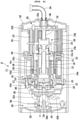
- the linear compressor 10 includes a cylinder 120 provided in the shell 101, a piston 130 that linearly reciprocates within the cylinder 120, and a motor assembly 140 that functions as a linear motor for applying driving force to the piston 130.
- the piston 130 may linearly reciprocate in the axial direction.
- the linear compressor 10 further include a suction muffler 150 coupled to the piston 130 to reduce a noise generated from the refrigerant suctioned through the suction pipe 104.
- the refrigerant suctioned through the suction pipe 104 flows into the piston 130 via the suction muffler 150. For example, while the refrigerant passes through the suction muffler 150, the flow noise of the refrigerant may be reduced.
- the suction muffler 150 includes a plurality of mufflers 151, 152, and 153.
- the plurality of mufflers 151, 152, and 153 include a first muffler 151, a second muffler 152, and a third muffler 153, which are coupled to each other.
- the first muffler 151 is disposed within the piston 130, and the second muffler 152 is coupled to a rear side of the first muffler 151. Also, the third muffler 153 accommodates the second muffler 152 therein and extends to a rear side of the first muffler 151. In view of a flow direction of the refrigerant, the refrigerant suctioned through the suction pipe 104 may successively pass through the third muffler 153, the second muffler 152, and the first muffler 151. In this process, the flow noise of the refrigerant may be reduced.
- the suction muffler 150 further includes a muffler filter 155.
- the muffler filter 155 may be disposed on an interface on which the first muffler 151 and the second muffler 152 are coupled to each other.
- the muffler filter 155 may have a circular shape, and an outer circumferential portion of the muffler filter 155 may be supported between the first and second mufflers 151 and 152.
- the "axial direction” may be understood as a direction in which the piston 130 reciprocates, i.e., the horizontal direction in FIG. 4 .
- a direction from the suction pipe 104 toward a compression space P i.e., a direction in which the refrigerant flows may be defined as a "front direction”
- a direction opposite to the front direction may be defined as a “rear direction”.
- the "radial direction” may be understood as a direction that is perpendicular to the direction in which the piston 130 reciprocates, i.e., the vertical direction in FIG. 4 .
- the piston 130 includes a piston body 131 having an approximately cylindrical shape and a piston flange 132 extending from the piston body 131 in the radial direction.
- the piston body 131 may reciprocate inside the cylinder 120, and the piston flange 132 may reciprocate outside the cylinder 120.
- the cylinder 120 includes a cylinder body 121 extending in the axial direction and a cylinder flange 122 disposed outside a front portion of the cylinder body 121. Also, the cylinder 120 is configured to accommodate at least a portion of the first muffler 151 and at least a portion of the piston body 131.
- the cylinder body 121 includes a gas inflow part (see reference numeral 126 of FIG. 6 ) into which at least a portion of the refrigerant discharged through a discharge valve 161 that will be described later is introduced.
- the gas inflow part 126 may be recessed inward from an outer circumferential surface of the cylinder body 121 in the radial direction.
- the gas inflow part 126 may be provided in plurality.
- the plurality of gas inflow parts 126 may be disposed to be spaced apart from each other along the outer circumferential surface of the cylinder body 121 with respect to a central axis in the axial direction.
- a cylinder filter 200 filtering foreign substances or oil components contained in the refrigerant gas is provided in the gas inflow part 126.
- the cylinder filter 200 includes a plurality of laminated filters. Also, a flow rate of the refrigerant passing through the cylinder filter 200 may be adjusted through the nozzle provided in the cylinder body 121 so that the refrigerant serves as a gas bearing between the piston 130 and the cylinder 120.
- the cylinder 120 has a compression space P in which the refrigerant is compressed by the piston 130. Also, a suction hole 133 through which the refrigerant is introduced into the compression space P is defined in a front surface of the piston body 131, and a suction valve 135 for selectively opening the suction hole 133 is disposed on a front side of the suction hole 133.
- a coupling hole 136a to which a predetermined coupling member 136 is coupled is defined in a front surface of the piston body 131.
- the coupling hole 136a may be defined in a center of the front surface of the piston body 131, and a plurality of suction holes 133 are defined to surround the coupling hole 136a.
- the coupling member 136 passes through the suction valve 135 and is coupled to the coupling hole 136a to fix the suction valve 135 to the front surface of the piston body 131.
- a discharge cover 160 defining a discharge space 160a for the refrigerant discharged from the compression space P and a discharge valve assembly 161 and 163 coupled to the discharge cover 160 to selectively discharge the refrigerant compressed in the compression space P are provided at a front side of the compression space P.
- the discharge space 160a includes a plurality of space parts that are partitioned by inner walls of the discharge cover 160. The plurality of space parts are disposed in the front and rear direction to communicate with each other.
- the discharge valve assemblies 161 and 163 include a discharge valve 161 that is opened when the pressure of the compression space P is above a discharge pressure to introduce the refrigerant into the discharge space 160a of the discharge cover 160 and a spring assembly 163 disposed between the discharge valve 161 and the discharge cover 160 to provide elastic force in the axial direction.
- the spring assembly 163 includes a valve spring 163a and a spring support part 163b for supporting the valve spring 163a to the discharge cover 160.
- the valve spring 163a may include a plate spring.
- the spring support part 163b may be integrally injection-molded to the valve spring 163a through an injection-molding process.
- the discharge valve 161 is coupled to the valve spring 163a, and a rear portion or a rear surface of the discharge valve 161 is disposed to be supported on the front surface of the cylinder 120.
- the compression space may be maintained in the sealed state.
- the compression space P may be opened to allow the refrigerant in the compression space P to be discharged.
- the compression space P may be understood as a space defined between the suction valve 135 and the discharge valve 161.
- the suction valve 135 may be disposed on one side of the compression space P
- the discharge valve 161 may be disposed on the other side of the compression space P, i.e., an opposite side of the suction valve 135.
- the suction valve 135 may be opened to suction the refrigerant into the compression space P.
- the suction valve 135 may compress the refrigerant of the compression space P in a state in which the suction valve 135 is closed.
- valve spring 163a when the pressure of the compression space P is above the discharge pressure, the valve spring 163a may be deformed forward to open the discharge valve 161.
- the refrigerant may be discharged from the compression space P into the discharge space 160a.
- the valve spring 163a When the discharge of the refrigerant is completed, the valve spring 163a may provide restoring force to the discharge valve 161 to close the discharge valve 161.
- the linear compressor 10 further includes a cover pipe 162a coupled to the discharge cover 160 to discharge the refrigerant flowing through the discharge space 160a of the discharge cover 160.
- the cover pipe 162a may be made of a metal material.
- the linear compressor 10 further includes a loop pipe 162b coupled to the cover pipe 162a to transfer the refrigerant flowing through the cover pipe 162a to the discharge pipe 105.
- the loop pipe 162a may have one side of the loop pipe 162b coupled to the cover pipe 162a and the other side coupled to the discharge pipe 105.
- the loop pipe 162b may be made of a flexible material and have a relatively long length. Also, the loop pipe 162b may roundly extend from the cover pipe 162a along the inner circumferential surface of the shell 101 and be coupled to the discharge pipe 105. For example, the loop pipe 162b may have a wound shape.
- the linear compressor 10 further includes a frame 110.
- the frame 110 is understood as a component for fixing the cylinder 120.
- the cylinder 120 may be press-fitted into the frame 110.
- each of the cylinder 120 and the frame 110 may be made of aluminum or an aluminum alloy material.
- the frame 110 includes a frame body 111 having an approximately cylindrical shape and a frame flange 112 extending from the frame body 111 in the radial direction.
- the frame body 111 is disposed to surround the cylinder 120. That is, the cylinder 120 may be disposed to be accommodated into the frame 111. Also, the frame flange 112 may be coupled to the discharge cover 160.
- a gas hole 114 through which at least a portion of the refrigerant discharged through the discharge valve 161 flows to the gas inflow part 126 is defined in the frame 110.
- the gas hole 114 communicates with the frame flange 112 and the frame body 111.
- a filter assembly 300 for filtering the foreign substances contained in the refrigerant to be introduced into the gas hole 114 is disposed on the frame flange 112.
- the filter assembly 300 may be installed to be press-fitted into an inner space defined in the frame flange 112.
- the motor assembly 140 includes an outer stator 141, an inner stator 148 disposed to be spaced inward from the outer stator 141, and a magnet 146 disposed in a space between the outer stator 141 and the inner stator 148.
- the magnet 146 may linearly reciprocate by a mutual electromagnetic force between the outer stator 141 and the inner stator 148. Also, the magnet 146 may be provided as a single magnet having one polarity or be provided by coupling a plurality of magnets having three polarities to each other.
- the inner stator 148 is fixed to an outer circumference of the frame body 111. Also, in the inner stator 148, the plurality of laminations are laminated outside the frame 111 in the radial direction.
- the outer stator 141 includes coil winding bodies 141b, 141c, and 141d and a stator core 141a.
- the coil winding bodies 141b, 141c, and 141d include a bobbin 141b and a coil 141c wound in a circumferential direction of the bobbin 141b.
- the coil winding bodies 141b, 141c, and 141d further include a terminal part 141d that guides a power line connected to the coil 141c so that the power line is led out or exposed to the outside of the outer stator 141.
- the terminal part 141d extends to pass through the frame flange 112.
- the stator core 141a includes a plurality of core blocks in which a plurality of laminations are laminated in a circumferential direction.
- the plurality of core blocks may be disposed to surround at least a portion of the coil winding bodies 141b and 141c.
- a stator cover 149 may be disposed on one side of the outer stator 141.
- the outer stator 141 may have one side supported by the frame flange 112 and the other side supported by the stator cover 149.
- the frame flange 112, the outer stator 141, and the stator cover 149 are sequentially disposed in the axial direction.
- the linear compressor 10 further includes a cover coupling member 149a for coupling the stator cover 149 to the frame flange 112.
- the cover coupling member 149a may pass through the stator cover 149 to extend forward to the frame 112 and then be coupled to the frame flange 112.
- the linear compressor 10 further includes a rear cover 170 coupled to the stator cover 149 to extend backward and supported by the second support device 185.
- the rear cover 170 includes three support legs, and the three support legs may be coupled to a rear surface of the stator cover 149.
- a spacer 181 may be disposed between the three support legs and the rear surface of the stator cover 149.
- a distance from the stator cover 149 to a rear end of the rear cover 170 may be determined by adjusting a thickness of the spacer 181.
- the linear compressor 10 further includes an inflow guide part 156 coupled to the rear cover 170 to guide an inflow of the refrigerant into the suction muffler 150. At least a portion of the inflow guide part 156 may be inserted into the suction muffler 150.
- the linear compressor 10 further includes a plurality of resonant springs 176a and 176b that are adjusted in natural frequency to allow the piston 130 to perform a resonant motion.
- the driving part that reciprocates within the linear compressor 10 may stably move by the action of the plurality of resonant springs 176a and 176b to reduce the vibration or noise due to the movement of the driving part.
- the linear compressor 10 further includes a first support device 165 coupled to the discharge cover 160 to support one side of the main body of the compressor 10.
- the first support device 165 may be disposed adjacent to the second shell cover 103 to elastically support the main body of the compressor 10.
- the first support device 165 includes a first support spring 166.
- the first support spring 166 may be coupled to the spring coupling part 101a.
- the linear compressor 10 further includes a second support device 185 coupled to the rear cover 170 to support the other side of the main body of the compressor 10.
- the second support device 185 may be coupled to the first shell cover 102 to elastically support the main body of the compressor 10.
- the second support device 185 includes a second support spring 186.
- the second support spring 186 may be coupled to the cover support part 102a.
- the linear compressor 10 includes the frame 110 and a plurality of sealing members for increasing coupling force between the peripheral components around the frame 110.
- Each of the plurality of sealing members may have a ring shape.
- the plurality of sealing members include a first sealing member 127 disposed at a portion at which the frame 110 and the discharge cover 160 are coupled to each other. Also, the plurality of sealing members further include second and third sealing members 128 and 129a provided to portions at which the frame 110 and the cylinder 120 are coupled to each other and a fourth sealing member 129b provided at a portion at which the frame 110 and the inner stator 148 are coupled to each other.
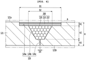
- FIG. 6 is an enlarged view illustrating a portion "A" of FIG. 5 .
- the linear compressor 10 further includes a cylinder filter coupled to the cylinder 120.
- the cylinder 120 includes a cylinder body 121 and a cylinder flange 122 disposed outside the front of the cylinder body 121.
- the cylinder body 121 may have a hollow cylindrical shape that lengthily extends in a horizontal direction or an axial direction. Also, the piston 130 is disposed in the cylinder body 121, and the frame 110 is disposed outside the cylinder body 121.
- the gas inflow part 126 recessed inward from the outer circumferential surface 121a of the cylinder body 121 in the radial direction is provided in the cylinder 120. Also, a cylinder filter 200 that will be described later is disposed on the gas inflow part 126.
- the gas inflow part 126 is a space into which at least a portion of the refrigerant discharged through the discharge valve 161 is introduced into the cylinder body 121.
- the gas inflow part 126 may be continuously provided along a circumference of the cylinder body 121. That is, the gas inflow part 126 may be recessed inward along the circumference of the cylinder body 121 in the radial direction.
- the gas inflow part 126 may have a circular band shape along the outer circumferential surface 121a of the cylinder body 121 with respect to a central axis thereof in the axial direction.
- the gas inflow part 126 may be provided in plurality.
- the plurality of gas inflow parts 126 may be disposed to be spaced apart from the cylinder body 121 in the axial direction.
- the gas inflow part 126 includes a first recess part 126a recessed by a predetermined depth H inward along a circumference of the outer circumferential surface 121a of the cylinder body 121 in the radial direction, a second recess part 126b further recessed by a predetermined depth H2 inward from the first recess part 126a in the radial direction, and a nozzle 126c further recessed by a predetermined depth H3 inward from the second recess part 126b in the radial direction.
- the first recess part 126a, the second recess part 126b, and the nozzle 126 may communicate with each other.
- the nozzle 126c may pass from the inside of the second recess part 126b up to the inner circumferential surface 121b of the cylinder body 121.
- the refrigerant gas introduced from the first recess part 126a may pass through the second recess part 126b and then move to the inside of the cylinder 120 through the nozzle 126c.
- the first recess part 126a may be understood as a space in which a first filter that will be described later is installed.
- the first recess part 126a may be recessed along the outer circumference of the cylinder body 121 to have a relatively large width D1.
- the first recess part 126a may have a circular band shape along the outer circumferential surface 121a of the cylinder body 121 with respect to a central axis thereof in the axial direction.
- the second recess part 126b may be understood as a space in which a second filter that will be described later is installed.
- the second recess part 126b may be further recessed inward from a bottom surface of the first recess part 126a in the radial direction.
- the second recess part 126b may be recessed along a circumference of the first recess part 126a.
- the second recess part 126b may have a width D2 less than that D1 of the first recess part 126a.
- the second recess part 126b may have an area that is gradually narrowed inward in the radial direction.
- the second recess part 126b may be recessed in a circular shape along a central point of the circumference of the first recess part 126a.
- centers of the first filter and the second filter may match each other.
- the nozzle 126c may be understood as a passage through which the refrigerant gas passing through the first filter and the second filter is introduced into the cylinder 120.
- the nozzle 126c may pass from a bottom surface of the second recess part 126b up to the inner circumferential surface 121b of the cylinder body 121.
- the nozzle 126c may have a width or diameter D3 that is relatively less than that of the second recess part 126b.
- the nozzle 126c may have a width or diameter of about 20 ⁇ m to about 40 ⁇ m.
- the nozzle 126c may be surrounded in a circular shape along the circumference of the bottom surface of the second recess part 126b.
- the nozzle 126c may have a circular shape along a central point of the bottom surface of the second recess part 126b.
- centers of the second filter and the nozzle 126c may match each other.
- a length H of the cylinder body 121 in a thickness direction may be defined as the sum of the recessed depths H1, H2, and H3 of the first recess part 126a, the second recess part 126b, and the nozzle 126c.
- the recessed depth H1 of the first recess part 126a may be less than that H2 of the second recess part 126b.
- the recessed depth H2 of the second recess part 126b may be greater than that H3 of the nozzle 126c.
- a ratio of each of the recessed depths H1, H2, and H3 to the length H of the cylinder body 121 in the thickness direction may be designed at a ratio of 0.16:0.44:0.4.
- the cylinder filter 200 may include a first filter 210 and a second filter 220 installed at an outlet-side of the first filter 210.
- the first filter 210 may be made of a metal material and seated on the first recess part 126a.
- the first filter 210 is disposed to be press-fitted into the first recess part 126a.
- the first filter 210 may include a metal fiber filter.
- the first filter 210 may be made of stainless steel.
- the first filter 210 may have a predetermined magnetic property and be prevented from being rusted.
- the first filter 210 may be provided into a mesh type having a plurality of filter holes (not shown).
- the filter hole may be designed to be a size of about 3 ⁇ m or less.
- the first filter 210 may be made of a porous metal material.
- the filter performance of the first filter 210 may be deteriorated even though a pressure and temperature are sharply changed for a long time.
- the second filter 220 includes a PET filter.
- the PET filter may be configured to adsorb fine particles and oil components contained in the refrigerant.
- the second filter 220 may include polyethylene phthalate (PET) and polytetrafluoroethylene (PTFE) membranes.
- a surface of the first filter 210 may be oil-repellent coated.
- a surface (top surface) corresponding to an inlet-side of the first filter 210 may be oil-repellent coated to reduce a surface area of oil disposed on an inlet surface of the first filter 210. That is, the reason in which the surface of the first filter 210 is oil-repellent coated is for preventing the oil from being spread by increasing surface tension of the oil. When the oil is not relatively spread, an occurrence of a phenomenon in which a filter hole defined in the first filter 210 is blocked by the oil may be reduced.
- the first filter 210 may be oil-repellent coated by using an oil-repellent agent.
- an oil-repellent coating layer 215 may be provided on an outer surface of the first filter 210, and thus, the surface area of the oil may be reduced by the oil-repellent coating layer 215.
- the cylinder filter 200 may have a structure in which the oil-repellent coating layer 215, the first filter 210, and the second filter 220 are sequentially laminated.
- the surface area of the oil may be reduced by the oil-repellent coating layer 215. Therefore, the oil contained in the refrigerant may be filtered by the oil-repellent coating layer 215 to prevent the oil from being permeated into the filter.
- FIG. 7 is an enlarged view illustrating a portion "B" of FIG. 5
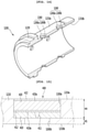
- FIG. 8 is a view illustrating a filter assembly according to the first embodiment
- FIG. 9 is a cross-sectional view taken along line II-II' of FIG. 8
- FIG. 10 is a view illustrating a discharge filter of the filter assembly according to the first embodiment.
- the linear compressor 10 further includes a filter assembly 300 coupled to the frame 110.
- a filter groove 115 that is recessed backward from a front surface of the frame flange 112 is defined in the frame flange 112.
- the filter groove 115 may have a cylindrical shape.
- the filter assembly 300 is disposed inside the filter groove 115.
- the filter assembly 300 may be press-fitted to be fixed to the filter groove 115.
- the linear compressor 10 may further include a filter sealing member 118 installed at the rear of the filter assembly 30, i.e., an outlet-side of the filter assembly 30.
- the filter sealing member 118 may have an approximately ring shape.
- the filter sealing member 118 may be placed on the filter groove 117.
- the filter sealing member 118 may be press-fitted into the filter groove 117.
- coupling force of the filter assembly 300 may increase by the filter sealing member 118.
- foreign substances existing in the shell 101 for example, oil or fine particles may be prevented from being permeated into the refrigerant passing through the filter assembly 300 by the filter sealing member 118.
- the filter assembly 300 includes a filter frame 310 having opened front and rear portions.
- a refrigerant inlet part 312 through which the refrigerant existing in the filter groove 115 is introduced into the filter frame 310 may be provided in the opened front portion of the filter frame 310. Also, a refrigerant discharge part 314 through which the refrigerant passing through the filter assembly 300 is discharged to the outside of the filter frame 310 is provided in the opened rear portion of the filter frame 310.
- the filter frame 310 may have a cylindrical case shape of which both sides are opened by the refrigerant inlet part 312 and the refrigerant discharge part 314.
- the filter frame 310 may be made of a brass material.
- the filter frame 310 includes a first frame 310a providing the refrigerant inlet part 312 and extending from the refrigerant inlet part 312 to the outside in the radial direction, a second frame 310b extending backward from the first frame 310a, and a third frame 310c extending inward from the second frame 310b in the radial direction to provide the refrigerant discharge part 314.
- Each of the first and third frames 310a and 310c may have an approximately ring shape. Also, a rear surface of the third frame 310c may be rounded and configured to press the filter sealing member 118.
- the filter assembly 300 further includes a discharge filter 330 provided in the filter frame 310 and filter support members 320 and 340 supporting the discharge filter 330.
- the discharge filter 330 includes a filter having lipophilicity.
- the discharge filter 330 may be made of a PET material having lipophilicity.
- oil contained in the refrigerant introduced into the filter assembly 300 may be filtered by the discharge filter 330 and thus may not pass through the filter assembly 300.
- At least one or more surfaces of the discharge filter 330 may be oil-repellent coated.
- the reason in which the surface of the discharge filter 330 is oil-repellent coated is for preventing the oil from being spread by increasing surface tension of the oil. When the oil is not relatively spread, an occurrence of a phenomenon in which a filter hole defined in the discharge filter 330 is blocked by the oil may be reduced.
- one surface of a front surface 330a and a rear surface 330b of the discharge filter 330 may be oil-repellent coated.
- the front surface 330a and the rear surface 330b of the discharge filter 330 may be oil-repellent coated by using the oil-repellent agent.
- an oil-repellent coating layer 332 may be disposed on the front surface 330a of the discharge filter 330.
- an oil-repellent coating layer 334 may be disposed on the rear surface 330b of the discharge filter 330.
- the oil-repellent coating layer is provided on the front surface 330a or the rear surface 330b of the discharge filter 330, the oil contained in the refrigerant may not pass through the discharge filter 330.
- the oil or foreign substances contained in the refrigerant gas may be previously filtered before the refrigerant gas is introduced into the cylinder nozzle to effectively prevent the nozzle from being blocked.
- the filter support members 320 and 340 include a first support member 320 disposed at the inlet-side of the discharge filter 330 to support the discharge filter 330 and a second support member 340 disposed at the outlet-side of the discharge filter 330 to support the discharge filter 330.
- the first support member 320 or the second support member 340 may include a fine metal mesh.
- first support member 320 may be supported by the first frame 310a, and the other side of the first support member 320 may support the discharge filter 330.
- second support member 340 may be supported by the third frame 310c, and the other side of the second support member 340 may support the discharge filter 330.
- the discharge filter 330 may be installed between the first and second support members 320 and 340 and thus be stably supported.
- first support member 320 may be supported by the first frame 310a, and the other side of the first support member 320 may support the oil-repellent coating layer 332 provided on the front surface 330a of the discharge filter 330.
- second support member 340 may be supported by the third frame 310c, and the other side of the second support member 320 may support the oil-repellent coating layer 334 provided on the rear surface 330b of the discharge filter 330.
- the discharge filter 330 may be firmly fixed due to the above-described configuration.
- the oil contained in the refrigerant introduced into the refrigerant inlet part 312 of the filter frame 310 may not pass through the discharge filter 330 to prevent the nozzle provided in the cylinder from being blocked.
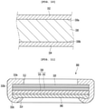
- FIG. 11 is a cross-sectional view of a filter assembly according to a second embodiment
- FIG. 12 is a view illustrating a discharge filter of the filter assembly according to the second embodiment.
- the current embodiment is the same as the first embodiment except for a structure of a filter assembly. Thus, only characterized parts of the current embodiment will be principally described below, and descriptions of the same part as that of the first embodiment will be quoted from the first embodiment.
- a filter assembly 300 includes a filter frame 310 having opened front and rear portions.
- a refrigerant inlet part 312 through which a refrigerant existing in a filter groove 115 is introduced into the filter frame 310 may be provided in the opened front portion of the filter frame 310. Also, a refrigerant outlet part 314 through which the refrigerant passing through the filter assembly 300 is discharged to the outside of the filter frame 310 is provided in the opened rear portion of the filter frame 310.
- the filter assembly 300 further includes a discharge filter 330 provided in the filter frame 310 and filter support members 320 and 340 supporting the discharge filter 330.
- the filter support members 320 and 340 have the same as those according to the first embodiment, and thus, their detailed description will be omitted.
- the discharge filter 330 includes a plurality of filters 331 and 333.
- the plurality of filters 331 and 333 include a first filter 331 and a second filter 333 disposed at an outlet-side of the first filter 331.
- the first filter 331 may be a mesh filter made of a metal material. That is, the first filter 331 may include a metal fiber filter having a plurality of filter holes.
- the first filter 331 may be formed of stainless steel.
- the first filter 210 may have a predetermined magnetic property and be prevented from being rusted.
- filter performance of the first filter 331 may be deteriorated even though a pressure and temperature are sharply changed for a long time.
- the second filter 333 includes a filter having lipophilicity.
- the second filter 330 may be made of a PET material having lipophilicity.
- oil contained in the refrigerant introduced into the filter assembly 300 may be filtered by the second filter 333 and thus may not pass through the filter assembly 300.
- At least one or more surfaces of the second filter 333 may be oil-repellent coated. That is, the second filter 333 may be the same as the discharge filter according to the foregoing first embodiment.
- an outer surface of the first filter 331 may also be oil-repellent coated.
- the front surface 331a of the first filter 331 may be oil-repellent coated to reduce a surface area of the oil contained in the refrigerant gas.
- the first filter 331 may be oil-repellent coated by using an oil-repellent agent. That is, an oil-repellent coating layer 335 may be disposed on the front surface 331a of the first filter 331.
- the first filter 331 may be disposed at the rear of the first support member 320
- the second filter 333 may be disposed at the rear of the first filter 331
- the second support member 340 may be disposed at the rear of the second filter 333
- the oil-repellent coating layer 335 may be disposed between the first support member 320 and the first filter 331 to filter the oil contained in the refrigerant by the first filter 331, and thus, the oil may not pass through the filter assembly 300.
- FIG. 13 is a view illustrating a state in which a cylinder filter is provided in a cylinder according to a third embodiment
- FIG. 14 is a view illustrating a configuration of the cylinder according to the third embodiment
- FIG. 15 is an enlarged view of a portion "C" of FIG. 13 .
- a cylinder 1200 according to a third embodiment includes a cylinder body 1210 and a cylinder flange 1220 disposed outside a front portion of the cylinder body 1210.
- the cylinder body 1210 may have a hollow cylindrical shape that lengthily extends in a horizontal direction or an axial direction. Also, the piston 130 is disposed in the cylinder body 1210, and a frame 110 is disposed outside the cylinder body 121.
- the cylinder 1200 includes a gas inflow part 1260 passing through the cylinder body 1210.
- the gas inflow part 1260 may be provided in plurality along a circumference of the cylinder body 1210.
- the gas inflow part 1260 is a space into which at least a portion of the refrigerant discharged through a discharge valve 161 is introduced into the cylinder body 1210.
- the gas inflow part 1260 may pass inward from an outer circumferential surface 1210a of the cylinder body 1210 in the radial direction. That is, the gas inflow part 1260 may be a portion that continuously passes from the outer circumferential surface 1210a of the cylinder body 1210 to an inner circumferential surface 1210b of the cylinder body 1210.
- the gas inflow part 1260 may include a seating groove 1260a that is recessed inward from the outer circumferential surface 1210a of the cylinder body 1210 by a predetermined depth in the radial direction and a through-hole 1260b passing from the seating groove 1260a to the inner circumferential surface 1210b of the cylinder body 1210. That is, the seating groove 1260a may communicate with the through-hole 1260b. However, the seating groove 1260a may have a diameter less than that of the through-hole 1260b.
- the seating groove 1260a provides a space in which a cylinder filter 420 that will be described later is mounted.
- the seating groove 1260a is recessed from the outer circumferential surface 1210a of the cylinder body 1210 by a predetermined depth to define a seating surface on which the cylinder filter 420 is seated.
- the seating groove 1260a may have a cylindrical shape.
- a horizontal cross-section of the seating surface may have a circular shape to support the cylindrical filter 420.
- the through-hole 1260b may be further recessed from the seating groove 1260a by a predetermined depth to extend up to the inner circumferential surface 1210b of the cylinder body 1210. Particularly, the through-hole 1260b passes from a central portion of the seating surface to the inner circumferential surface 1210b of the cylinder body 1210.
- the through-hole 1260b has a diameter less than that of the seating groove 1260a, a seating surface on which the cylinder filter 420 is seated may be provided.
- the through-hole 126b may have a circular shape.
- the refrigerant gas passing through the cylinder filter 420 may be uniformly spread into the space between the piston 130 and the cylinder 1200 through the through-hole 1260b.
- the gas inflow part 1260 may be provided in plurality, which are spaced apart from each other along an outer surface of the cylinder 1200.
- the plurality of gas inflow parts 1260 may be disposed to be spaced apart from each other along the outer circumferential surface 1210a of the cylinder body 1210 with respect to a central axis in the axial direction.
- the plurality of gas inflow parts 1260 may be disposed at a certain interval along the circumference of the cylinder 1200. However, this embodiment is not limited thereto.
- the gas inflow parts 1260 may be variously designed in number and position.
- the linear compressor 10 further include a plate 410 installed on the cylinder 1200.
- the plate 410 may be seated on the seating groove 1260a to cover the through-hole 1260b. Also, the plate 410 may support a cylinder filter 420 that will be described later.
- the plate 410 and the cylinder filter 420 may be called a cylinder filter assembly 400.
- the plate 410 may have a disc shape having a predetermined area. Also, a nozzle 411 for adjusting a flow rate of the refrigerant may be provided in the plate 410.
- the nozzle 411 may be provided to pass through a predetermined point of the plate 410.
- the nozzle 411 may pass through a central point of the top surface of the plate 410 in a downward direction.
- the nozzle 411 may have an area that is gradually narrowed inward in the radial direction.
- an inner end of the nozzle 411 may provide a tip portion.
- the flow rate of the refrigerant gas may be adjusted by the diameter of the nozzle 411.
- a surface (a top surface or a bottom surface) of the plate 410 may be oil-repellent coated.
- the top surface 410a of the plate 410 may be oil-repellent coated to reduce a surface area of oil contained in the refrigerant gas.
- the plate 410 may be oil-repellent coated by using an oil-repellent agent.
- an oil-repellent coating layer 412 may be provided on the top surface of the plate 410, and thus, surface tension of the oil may increase by the oil-repellent coating layer 412.
- the oil may not be spread on the top surface 410a of the plate 410 to prevent the nozzle 411 provided in the plate 410 from being blocked by the oil.
- the linear compressor 10 further include a cylinder filter 420 installed in the cylinder 1200.
- the cylinder filter 420 is seated on the seating groove 1260a to filter the foreign substances or oil contained in the refrigerant gas.
- the cylinder filter 420 is made of a metal material and seated on the plate 410.
- the cylinder filter 420 may be disposed to be press-fitted into the seating groove 1260a.
- the cylinder filter 420 may be made of stainless steel. Also, the cylinder filter 420 may have a magnetic property and be prevented from being rusted. Also, the cylinder filter 420 may be provided into a mesh type having a plurality of filter holes (not shown). For example, the filter hole may be designed to be a size of about 3 ⁇ m or less.
- the cylinder filter 420 may be made of a porous metal material. Thus, filter performance of the cylinder filter 420 may be deteriorated even though a pressure and temperature are sharply changed for a long time.
- a surface (a top surface or a bottom surface) of the cylinder filter 420 may be oil-repellent coated.
- the top surface 420a of the cylinder filter 420 may be oil-repellent coated to reduce a surface area of the oil contained in the refrigerant gas.
- the cylinder filter 420 may be oil-repellent coated by using an oil-repellent agent.
- an oil-repellent coating layer 422 may be provided on the top surface 420a of the cylinder filter 420, and thus, the surface tension of the oil may increase by the oil-repellent coating layer 422.
- the oil may not be spread on the top surface 420a of the cylinder filter 420 to prevent the nozzle hole provided in the cylinder filter 420 from being blocked by the oil.
- the surface (top surface or bottom surface) of the plate 410 or the surface (top surface or bottom surface) of the cylinder filter 420 may be oil-repellent coated, and thus, the oil contained in the refrigerant may be prevented from being introduced into the nozzle 411 provided in the plate 410. That is, if even any one of the plate 410 and the cylinder filter 420 is oil-repellent coated, the oil may be prevented from being introduced into the nozzle 410.
- the linear compressor including the above-described constituents according to the embodiment may have the following effects.
- the nozzle through which the refrigerant gas passes may be provided in the cylinder, and the cylinder filter of which at least one or more surfaces are oil-repellent coated may be provided at the inlet-side of the nozzle to adjust the flow rate of the refrigerant gas that is used as the gas bearing and also filter the foreign substances contained in the refrigerant gas.
- the nozzle through which the refrigerant gas is introduced into the cylinder is minimized in diameter or number, the blocking of the nozzle may be prevented while maintaining the performance of the gas bearing.
- the consumption flow rate of the refrigerant gas is relatively smaller than that of the refrigerant gas according to the related art, the piston supporting force equal to or greater than that according to the related art may be secured.
- the cylinder filter provided at the inlet-side of the cylinder nozzle may be oil-repellent coated to effectively prevent the nozzle from being blocked without changing the structure of the existing compressor, thereby reducing the product price and improving general versatility.
- the cylinder filter may include the plurality of filters made of materials different from each other, and the plurality of filters may be laminated in the flow direction of the refrigerant.
- the oil or foreign substances contained in the refrigerant gas may be effectively filtered.
- the discharge filter that is oil-repellent coated may be provided in the frame through which the refrigerant gas is introduced into the cylinder nozzle to previously filer the oil or foreign substances contained in the refrigerant gas before the refrigerant gas is introduced into the cylinder nozzle, thereby effectively prevent the nozzle from being blocked.
Landscapes
- Engineering & Computer Science (AREA)
- Mechanical Engineering (AREA)
- General Engineering & Computer Science (AREA)
- Chemical & Material Sciences (AREA)
- Chemical Kinetics & Catalysis (AREA)
- Life Sciences & Earth Sciences (AREA)
- Geology (AREA)
- Compressor (AREA)
Claims (10)
- Compresseur linéaire (10) comprenant :une enveloppe (101);un cylindre (120) disposé dans l'enveloppe (101) pour définir un espace de compression (P) pour un fluide frigorigène ;un piston (130) installé pour effectuer un mouvement de va-et-vient dans le cylindre (120) ;une buse (126c) qui est située dans le cylindre (120) et à travers laquelle passe une portion du fluide frigorigène introduit dans l'espace de compression (P) ; etun filtre de cylindre (200) installé dans le cylindre (120) et disposé au niveau d'un côté entrée de la buse (126c),caractérisé en ce qu'au moins une ou plusieurs surfaces du filtre de cylindre (200) sont revêtues d'un agent oléofuge,dans lequel une partie d'écoulement entrant de gaz (1260) passant d'une surface circonférentielle extérieure (1210a) à une surface circonférentielle intérieure (1210b) du cylindre (1200) est située dans le cylindre (1200), etune plaque (410) dans laquelle est située la buse (411) est disposée à l'intérieur de la partie d'écoulement entrant de gaz (1260).
- Compresseur linéaire selon la revendication 1, dans lequel le filtre de cylindre (420) comprend un filtre à fibres métalliques présentant une pluralité de trous de filtrage, et la plaque (410) est composée d'une matière plastique industrielle.
- Compresseur linéaire (10) selon la revendication 1 ou 2, dans lequel la partie d'écoulement entrant de gaz (1260) comprend :une rainure de placement (1260a) enfoncée vers l'intérieur par rapport à la surface circonférentielle extérieure (1210a) du cylindre (1200) dans une direction radiale ; etun trou traversant (1260b) passant de la rainure de placement (1260a) à la surface circonférentielle intérieure (1210b) du cylindre (1200),dans lequel la plaque (410) est placée dans la rainure de placement (1260a) pour recouvrir le trou traversant (1260b).
- Compresseur linéaire (10) selon la revendication 3, dans lequel la rainure de placement (1260a) présente un diamètre supérieur à celui du trou traversant (1260b).
- Compresseur linéaire (10) selon les revendications 3 à 4, dans lequel le filtre de cylindre (420) est stratifié sur la plaque (410) à l'intérieur de la rainure de placement (1260a).
- Compresseur linéaire selon les revendications 3 à 5, dans lequel le filtre de cylindre (200) est disposé pour être ajusté par pression dans la rainure de placement (1260a) et placé sur la plaque (410).
- Compresseur linéaire (10) selon les revendications 1 à 6, dans lequel une surface correspondant à un côté entrée du filtre de cylindre (420) est revêtue d'un agent oléofuge et/ou
une surface correspondant à un côté sortie du filtre de cylindre (420) est revêtue d'un agent oléofuge. - Compresseur linéaire (10) selon l'une quelconque des revendications 3 à 7, dans lequel une portion du fluide frigorigène rejetée de l'espace de compression (P) passe à travers le filtre de cylindre (420) et est introduite dans le trou traversant (1260b) de la partie d'écoulement entrant de gaz (1260) à travers la buse (411) de la plaque (410).
- Compresseur linéaire selon les revendications 1 à 8, dans lequel une surface de la plaque (410) est revêtue d'un agent oléofuge.
- Compresseur linéaire selon l'une quelconque des revendications 1 à 9, dans lequel la buse (411) présente une coupe qui rétrécit progressivement vers l'intérieur dans la direction radiale.
Applications Claiming Priority (2)
| Application Number | Priority Date | Filing Date | Title |
|---|---|---|---|
| KR1020180106557A KR102103184B1 (ko) | 2018-09-06 | 2018-09-06 | 리니어 압축기 |
| EP19189568.9A EP3620655B1 (fr) | 2018-09-06 | 2019-08-01 | Compresseur linéaire |
Related Parent Applications (2)
| Application Number | Title | Priority Date | Filing Date |
|---|---|---|---|
| EP19189568.9A Division EP3620655B1 (fr) | 2018-09-06 | 2019-08-01 | Compresseur linéaire |
| EP19189568.9A Division-Into EP3620655B1 (fr) | 2018-09-06 | 2019-08-01 | Compresseur linéaire |
Publications (2)
| Publication Number | Publication Date |
|---|---|
| EP3845762A1 EP3845762A1 (fr) | 2021-07-07 |
| EP3845762B1 true EP3845762B1 (fr) | 2022-02-16 |
Family
ID=67514492
Family Applications (2)
| Application Number | Title | Priority Date | Filing Date |
|---|---|---|---|
| EP19189568.9A Active EP3620655B1 (fr) | 2018-09-06 | 2019-08-01 | Compresseur linéaire |
| EP21154266.7A Active EP3845762B1 (fr) | 2018-09-06 | 2019-08-01 | Compresseur linéaire |
Family Applications Before (1)
| Application Number | Title | Priority Date | Filing Date |
|---|---|---|---|
| EP19189568.9A Active EP3620655B1 (fr) | 2018-09-06 | 2019-08-01 | Compresseur linéaire |
Country Status (4)
| Country | Link |
|---|---|
| US (1) | US11644030B2 (fr) |
| EP (2) | EP3620655B1 (fr) |
| KR (1) | KR102103184B1 (fr) |
| CN (1) | CN210714975U (fr) |
Families Citing this family (1)
| Publication number | Priority date | Publication date | Assignee | Title |
|---|---|---|---|---|
| KR20260016362A (ko) * | 2024-07-26 | 2026-02-03 | 삼성전자주식회사 | 압축기 |
Family Cites Families (13)
| Publication number | Priority date | Publication date | Assignee | Title |
|---|---|---|---|---|
| JP2854223B2 (ja) * | 1993-09-08 | 1999-02-03 | ジャパンゴアテックス株式会社 | 撥油防水性通気フィルター |
| DE102004061940A1 (de) * | 2004-12-22 | 2006-07-06 | Aerolas Gmbh, Aerostatische Lager- Lasertechnik | Kolben-Zylinder-Einheit |
| DE102006042021A1 (de) * | 2006-09-07 | 2008-03-27 | BSH Bosch und Siemens Hausgeräte GmbH | Verdichter mit gasdruckgelagertem Kolben |
| JP5338568B2 (ja) * | 2009-08-26 | 2013-11-13 | トヨタ紡織株式会社 | オイルミストセパレータ |
| US9005334B2 (en) * | 2010-06-16 | 2015-04-14 | Nitto Denko Corporation | Water-proof air-permeable filter and use of the same |
| EP3363529A1 (fr) * | 2011-02-28 | 2018-08-22 | Nitto Denko Corporation | Filtre de ventilation oléofuge |
| BRPI1105473B1 (pt) * | 2011-11-16 | 2020-12-01 | Embraco Indústria De Compressores E Soluções Em Refrigeração Ltda. | compressor de gás compreendendo uma mancalização aerostática |
| CN104220141B (zh) * | 2012-04-06 | 2016-01-20 | 日东电工株式会社 | 赋予了拒油性的带粘合层的透气过滤器 |
| KR102121585B1 (ko) * | 2013-09-16 | 2020-06-11 | 엘지전자 주식회사 | 왕복동식 압축기 |
| KR102234726B1 (ko) * | 2014-06-24 | 2021-04-02 | 엘지전자 주식회사 | 리니어 압축기 |
| KR102257479B1 (ko) * | 2016-05-03 | 2021-05-31 | 엘지전자 주식회사 | 리니어 압축기 |
| KR102270355B1 (ko) | 2016-10-11 | 2021-06-30 | 엘지전자 주식회사 | 리니어 압축기 |
| KR102605743B1 (ko) * | 2017-01-10 | 2023-11-24 | 엘지전자 주식회사 | 리니어 압축기 |
-
2018
- 2018-09-06 KR KR1020180106557A patent/KR102103184B1/ko active Active
-
2019
- 2019-07-24 CN CN201921179619.8U patent/CN210714975U/zh active Active
- 2019-08-01 EP EP19189568.9A patent/EP3620655B1/fr active Active
- 2019-08-01 EP EP21154266.7A patent/EP3845762B1/fr active Active
- 2019-08-16 US US16/542,685 patent/US11644030B2/en active Active
Also Published As
| Publication number | Publication date |
|---|---|
| US11644030B2 (en) | 2023-05-09 |
| US20200080553A1 (en) | 2020-03-12 |
| KR102103184B1 (ko) | 2020-04-22 |
| KR20200028189A (ko) | 2020-03-16 |
| CN210714975U (zh) | 2020-06-09 |
| EP3620655A1 (fr) | 2020-03-11 |
| EP3620655B1 (fr) | 2021-03-17 |
| EP3845762A1 (fr) | 2021-07-07 |
Similar Documents
| Publication | Publication Date | Title |
|---|---|---|
| EP3346127B1 (fr) | Compresseur linéaire | |
| EP3242024B1 (fr) | Compresseur linéaire | |
| RU2677778C2 (ru) | Линейный компрессор | |
| EP2960503B1 (fr) | Compresseur linéaire | |
| EP3783223B1 (fr) | Compresseur linéaire | |
| EP3587813B1 (fr) | Compresseur à mouvement alternatif | |
| CN107339210B (zh) | 线性压缩机 | |
| EP3249224B1 (fr) | Compresseur linéaire | |
| EP3591230B1 (fr) | Compresseur linéaire | |
| EP3845762B1 (fr) | Compresseur linéaire | |
| US20200149518A1 (en) | Linear compressor | |
| EP3591228B1 (fr) | Compresseur linéaire | |
| CN109098950B (zh) | 线性压缩机 | |
| KR102217342B1 (ko) | 리니어 압축기 | |
| CN211900908U (zh) | 线性压缩机 |
Legal Events
| Date | Code | Title | Description |
|---|---|---|---|
| STAA | Information on the status of an ep patent application or granted ep patent |
Free format text: STATUS: REQUEST FOR EXAMINATION WAS MADE |
|
| PUAI | Public reference made under article 153(3) epc to a published international application that has entered the european phase |
Free format text: ORIGINAL CODE: 0009012 |
|
| 17P | Request for examination filed |
Effective date: 20210228 |
|
| AC | Divisional application: reference to earlier application |
Ref document number: 3620655 Country of ref document: EP Kind code of ref document: P |
|
| AK | Designated contracting states |
Kind code of ref document: A1 Designated state(s): AL AT BE BG CH CY CZ DE DK EE ES FI FR GB GR HR HU IE IS IT LI LT LU LV MC MK MT NL NO PL PT RO RS SE SI SK SM TR |
|
| RBV | Designated contracting states (corrected) |
Designated state(s): AL AT BE BG CH CY CZ DE DK EE ES FI FR GB GR HR HU IE IS IT LI LT LU LV MC MK MT NL NO PL PT RO RS SE SI SK SM TR |
|
| GRAP | Despatch of communication of intention to grant a patent |
Free format text: ORIGINAL CODE: EPIDOSNIGR1 |
|
| STAA | Information on the status of an ep patent application or granted ep patent |
Free format text: STATUS: GRANT OF PATENT IS INTENDED |
|
| INTG | Intention to grant announced |
Effective date: 20210927 |
|
| GRAS | Grant fee paid |
Free format text: ORIGINAL CODE: EPIDOSNIGR3 |
|
| GRAA | (expected) grant |
Free format text: ORIGINAL CODE: 0009210 |
|
| STAA | Information on the status of an ep patent application or granted ep patent |
Free format text: STATUS: THE PATENT HAS BEEN GRANTED |
|
| AC | Divisional application: reference to earlier application |
Ref document number: 3620655 Country of ref document: EP Kind code of ref document: P |
|
| AK | Designated contracting states |
Kind code of ref document: B1 Designated state(s): AL AT BE BG CH CY CZ DE DK EE ES FI FR GB GR HR HU IE IS IT LI LT LU LV MC MK MT NL NO PL PT RO RS SE SI SK SM TR |
|
| REG | Reference to a national code |
Ref country code: GB Ref legal event code: FG4D |
|
| REG | Reference to a national code |
Ref country code: CH Ref legal event code: EP |
|
| REG | Reference to a national code |
Ref country code: DE Ref legal event code: R096 Ref document number: 602019011747 Country of ref document: DE |
|
| REG | Reference to a national code |
Ref country code: AT Ref legal event code: REF Ref document number: 1469034 Country of ref document: AT Kind code of ref document: T Effective date: 20220315 |
|
| REG | Reference to a national code |
Ref country code: IE Ref legal event code: FG4D |
|
| REG | Reference to a national code |
Ref country code: LT Ref legal event code: MG9D |
|
| REG | Reference to a national code |
Ref country code: NL Ref legal event code: MP Effective date: 20220216 |
|
| REG | Reference to a national code |
Ref country code: AT Ref legal event code: MK05 Ref document number: 1469034 Country of ref document: AT Kind code of ref document: T Effective date: 20220216 |
|
| PG25 | Lapsed in a contracting state [announced via postgrant information from national office to epo] |
Ref country code: SE Free format text: LAPSE BECAUSE OF FAILURE TO SUBMIT A TRANSLATION OF THE DESCRIPTION OR TO PAY THE FEE WITHIN THE PRESCRIBED TIME-LIMIT Effective date: 20220216 Ref country code: RS Free format text: LAPSE BECAUSE OF FAILURE TO SUBMIT A TRANSLATION OF THE DESCRIPTION OR TO PAY THE FEE WITHIN THE PRESCRIBED TIME-LIMIT Effective date: 20220216 Ref country code: PT Free format text: LAPSE BECAUSE OF FAILURE TO SUBMIT A TRANSLATION OF THE DESCRIPTION OR TO PAY THE FEE WITHIN THE PRESCRIBED TIME-LIMIT Effective date: 20220616 Ref country code: NO Free format text: LAPSE BECAUSE OF FAILURE TO SUBMIT A TRANSLATION OF THE DESCRIPTION OR TO PAY THE FEE WITHIN THE PRESCRIBED TIME-LIMIT Effective date: 20220516 Ref country code: NL Free format text: LAPSE BECAUSE OF FAILURE TO SUBMIT A TRANSLATION OF THE DESCRIPTION OR TO PAY THE FEE WITHIN THE PRESCRIBED TIME-LIMIT Effective date: 20220216 Ref country code: LT Free format text: LAPSE BECAUSE OF FAILURE TO SUBMIT A TRANSLATION OF THE DESCRIPTION OR TO PAY THE FEE WITHIN THE PRESCRIBED TIME-LIMIT Effective date: 20220216 Ref country code: HR Free format text: LAPSE BECAUSE OF FAILURE TO SUBMIT A TRANSLATION OF THE DESCRIPTION OR TO PAY THE FEE WITHIN THE PRESCRIBED TIME-LIMIT Effective date: 20220216 Ref country code: ES Free format text: LAPSE BECAUSE OF FAILURE TO SUBMIT A TRANSLATION OF THE DESCRIPTION OR TO PAY THE FEE WITHIN THE PRESCRIBED TIME-LIMIT Effective date: 20220216 Ref country code: BG Free format text: LAPSE BECAUSE OF FAILURE TO SUBMIT A TRANSLATION OF THE DESCRIPTION OR TO PAY THE FEE WITHIN THE PRESCRIBED TIME-LIMIT Effective date: 20220516 |
|
| PG25 | Lapsed in a contracting state [announced via postgrant information from national office to epo] |
Ref country code: PL Free format text: LAPSE BECAUSE OF FAILURE TO SUBMIT A TRANSLATION OF THE DESCRIPTION OR TO PAY THE FEE WITHIN THE PRESCRIBED TIME-LIMIT Effective date: 20220216 Ref country code: LV Free format text: LAPSE BECAUSE OF FAILURE TO SUBMIT A TRANSLATION OF THE DESCRIPTION OR TO PAY THE FEE WITHIN THE PRESCRIBED TIME-LIMIT Effective date: 20220216 Ref country code: GR Free format text: LAPSE BECAUSE OF FAILURE TO SUBMIT A TRANSLATION OF THE DESCRIPTION OR TO PAY THE FEE WITHIN THE PRESCRIBED TIME-LIMIT Effective date: 20220517 Ref country code: FI Free format text: LAPSE BECAUSE OF FAILURE TO SUBMIT A TRANSLATION OF THE DESCRIPTION OR TO PAY THE FEE WITHIN THE PRESCRIBED TIME-LIMIT Effective date: 20220216 Ref country code: AT Free format text: LAPSE BECAUSE OF FAILURE TO SUBMIT A TRANSLATION OF THE DESCRIPTION OR TO PAY THE FEE WITHIN THE PRESCRIBED TIME-LIMIT Effective date: 20220216 |
|
| PG25 | Lapsed in a contracting state [announced via postgrant information from national office to epo] |
Ref country code: IS Free format text: LAPSE BECAUSE OF FAILURE TO SUBMIT A TRANSLATION OF THE DESCRIPTION OR TO PAY THE FEE WITHIN THE PRESCRIBED TIME-LIMIT Effective date: 20220617 |
|
| PG25 | Lapsed in a contracting state [announced via postgrant information from national office to epo] |
Ref country code: SM Free format text: LAPSE BECAUSE OF FAILURE TO SUBMIT A TRANSLATION OF THE DESCRIPTION OR TO PAY THE FEE WITHIN THE PRESCRIBED TIME-LIMIT Effective date: 20220216 Ref country code: SK Free format text: LAPSE BECAUSE OF FAILURE TO SUBMIT A TRANSLATION OF THE DESCRIPTION OR TO PAY THE FEE WITHIN THE PRESCRIBED TIME-LIMIT Effective date: 20220216 Ref country code: RO Free format text: LAPSE BECAUSE OF FAILURE TO SUBMIT A TRANSLATION OF THE DESCRIPTION OR TO PAY THE FEE WITHIN THE PRESCRIBED TIME-LIMIT Effective date: 20220216 Ref country code: EE Free format text: LAPSE BECAUSE OF FAILURE TO SUBMIT A TRANSLATION OF THE DESCRIPTION OR TO PAY THE FEE WITHIN THE PRESCRIBED TIME-LIMIT Effective date: 20220216 Ref country code: DK Free format text: LAPSE BECAUSE OF FAILURE TO SUBMIT A TRANSLATION OF THE DESCRIPTION OR TO PAY THE FEE WITHIN THE PRESCRIBED TIME-LIMIT Effective date: 20220216 Ref country code: CZ Free format text: LAPSE BECAUSE OF FAILURE TO SUBMIT A TRANSLATION OF THE DESCRIPTION OR TO PAY THE FEE WITHIN THE PRESCRIBED TIME-LIMIT Effective date: 20220216 |
|
| REG | Reference to a national code |
Ref country code: DE Ref legal event code: R097 Ref document number: 602019011747 Country of ref document: DE |
|
| PG25 | Lapsed in a contracting state [announced via postgrant information from national office to epo] |
Ref country code: AL Free format text: LAPSE BECAUSE OF FAILURE TO SUBMIT A TRANSLATION OF THE DESCRIPTION OR TO PAY THE FEE WITHIN THE PRESCRIBED TIME-LIMIT Effective date: 20220216 |
|
| PLBE | No opposition filed within time limit |
Free format text: ORIGINAL CODE: 0009261 |
|
| STAA | Information on the status of an ep patent application or granted ep patent |
Free format text: STATUS: NO OPPOSITION FILED WITHIN TIME LIMIT |
|
| 26N | No opposition filed |
Effective date: 20221117 |
|
| PG25 | Lapsed in a contracting state [announced via postgrant information from national office to epo] |
Ref country code: MC Free format text: LAPSE BECAUSE OF FAILURE TO SUBMIT A TRANSLATION OF THE DESCRIPTION OR TO PAY THE FEE WITHIN THE PRESCRIBED TIME-LIMIT Effective date: 20220216 |
|
| REG | Reference to a national code |
Ref country code: CH Ref legal event code: PL |
|
| PG25 | Lapsed in a contracting state [announced via postgrant information from national office to epo] |
Ref country code: LU Free format text: LAPSE BECAUSE OF NON-PAYMENT OF DUE FEES Effective date: 20220801 Ref country code: LI Free format text: LAPSE BECAUSE OF NON-PAYMENT OF DUE FEES Effective date: 20220831 Ref country code: CH Free format text: LAPSE BECAUSE OF NON-PAYMENT OF DUE FEES Effective date: 20220831 |
|
| REG | Reference to a national code |
Ref country code: BE Ref legal event code: MM Effective date: 20220831 |
|
| PG25 | Lapsed in a contracting state [announced via postgrant information from national office to epo] |
Ref country code: IE Free format text: LAPSE BECAUSE OF NON-PAYMENT OF DUE FEES Effective date: 20220801 Ref country code: FR Free format text: LAPSE BECAUSE OF NON-PAYMENT OF DUE FEES Effective date: 20220831 |
|
| PG25 | Lapsed in a contracting state [announced via postgrant information from national office to epo] |
Ref country code: BE Free format text: LAPSE BECAUSE OF NON-PAYMENT OF DUE FEES Effective date: 20220831 |
|
| GBPC | Gb: european patent ceased through non-payment of renewal fee |
Effective date: 20230801 |
|
| PG25 | Lapsed in a contracting state [announced via postgrant information from national office to epo] |
Ref country code: MK Free format text: LAPSE BECAUSE OF FAILURE TO SUBMIT A TRANSLATION OF THE DESCRIPTION OR TO PAY THE FEE WITHIN THE PRESCRIBED TIME-LIMIT Effective date: 20220216 Ref country code: CY Free format text: LAPSE BECAUSE OF FAILURE TO SUBMIT A TRANSLATION OF THE DESCRIPTION OR TO PAY THE FEE WITHIN THE PRESCRIBED TIME-LIMIT Effective date: 20220216 |
|
| PG25 | Lapsed in a contracting state [announced via postgrant information from national office to epo] |
Ref country code: HU Free format text: LAPSE BECAUSE OF FAILURE TO SUBMIT A TRANSLATION OF THE DESCRIPTION OR TO PAY THE FEE WITHIN THE PRESCRIBED TIME-LIMIT; INVALID AB INITIO Effective date: 20190801 |
|
| PG25 | Lapsed in a contracting state [announced via postgrant information from national office to epo] |
Ref country code: TR Free format text: LAPSE BECAUSE OF FAILURE TO SUBMIT A TRANSLATION OF THE DESCRIPTION OR TO PAY THE FEE WITHIN THE PRESCRIBED TIME-LIMIT Effective date: 20220216 |
|
| PG25 | Lapsed in a contracting state [announced via postgrant information from national office to epo] |
Ref country code: GB Free format text: LAPSE BECAUSE OF NON-PAYMENT OF DUE FEES Effective date: 20230801 |
|
| PG25 | Lapsed in a contracting state [announced via postgrant information from national office to epo] |
Ref country code: GB Free format text: LAPSE BECAUSE OF NON-PAYMENT OF DUE FEES Effective date: 20230801 |
|
| PG25 | Lapsed in a contracting state [announced via postgrant information from national office to epo] |
Ref country code: MT Free format text: LAPSE BECAUSE OF FAILURE TO SUBMIT A TRANSLATION OF THE DESCRIPTION OR TO PAY THE FEE WITHIN THE PRESCRIBED TIME-LIMIT Effective date: 20220216 |
|
| PGFP | Annual fee paid to national office [announced via postgrant information from national office to epo] |
Ref country code: DE Payment date: 20250707 Year of fee payment: 7 |
|
| PGFP | Annual fee paid to national office [announced via postgrant information from national office to epo] |
Ref country code: IT Payment date: 20250710 Year of fee payment: 7 |
|
| PG25 | Lapsed in a contracting state [announced via postgrant information from national office to epo] |
Ref country code: SI Free format text: LAPSE BECAUSE OF FAILURE TO SUBMIT A TRANSLATION OF THE DESCRIPTION OR TO PAY THE FEE WITHIN THE PRESCRIBED TIME-LIMIT Effective date: 20220216 |