EP3845785A1 - Dispositif d'étanchéité - Google Patents
Dispositif d'étanchéité Download PDFInfo
- Publication number
- EP3845785A1 EP3845785A1 EP19855101.2A EP19855101A EP3845785A1 EP 3845785 A1 EP3845785 A1 EP 3845785A1 EP 19855101 A EP19855101 A EP 19855101A EP 3845785 A1 EP3845785 A1 EP 3845785A1
- Authority
- EP
- European Patent Office
- Prior art keywords
- water
- sealing member
- sealing
- discharge protrusions
- inclined surface
- Prior art date
- Legal status (The legal status is an assumption and is not a legal conclusion. Google has not performed a legal analysis and makes no representation as to the accuracy of the status listed.)
- Withdrawn
Links
Images




Classifications
-
- F—MECHANICAL ENGINEERING; LIGHTING; HEATING; WEAPONS; BLASTING
- F16—ENGINEERING ELEMENTS AND UNITS; GENERAL MEASURES FOR PRODUCING AND MAINTAINING EFFECTIVE FUNCTIONING OF MACHINES OR INSTALLATIONS; THERMAL INSULATION IN GENERAL
- F16J—PISTONS; CYLINDERS; SEALINGS
- F16J15/00—Sealings
- F16J15/16—Sealings between relatively-moving surfaces
- F16J15/164—Sealings between relatively-moving surfaces the sealing action depending on movements; pressure difference, temperature or presence of leaking fluid
-
- F—MECHANICAL ENGINEERING; LIGHTING; HEATING; WEAPONS; BLASTING
- F16—ENGINEERING ELEMENTS AND UNITS; GENERAL MEASURES FOR PRODUCING AND MAINTAINING EFFECTIVE FUNCTIONING OF MACHINES OR INSTALLATIONS; THERMAL INSULATION IN GENERAL
- F16C—SHAFTS; FLEXIBLE SHAFTS; ELEMENTS OR CRANKSHAFT MECHANISMS; ROTARY BODIES OTHER THAN GEARING ELEMENTS; BEARINGS
- F16C19/00—Bearings with rolling contact, for exclusively rotary movement
- F16C19/02—Bearings with rolling contact, for exclusively rotary movement with bearing balls essentially of the same size in one or more circular rows
- F16C19/14—Bearings with rolling contact, for exclusively rotary movement with bearing balls essentially of the same size in one or more circular rows for both radial and axial load
- F16C19/18—Bearings with rolling contact, for exclusively rotary movement with bearing balls essentially of the same size in one or more circular rows for both radial and axial load with two or more rows of balls
- F16C19/181—Bearings with rolling contact, for exclusively rotary movement with bearing balls essentially of the same size in one or more circular rows for both radial and axial load with two or more rows of balls with angular contact
- F16C19/183—Bearings with rolling contact, for exclusively rotary movement with bearing balls essentially of the same size in one or more circular rows for both radial and axial load with two or more rows of balls with angular contact with two rows at opposite angles
- F16C19/184—Bearings with rolling contact, for exclusively rotary movement with bearing balls essentially of the same size in one or more circular rows for both radial and axial load with two or more rows of balls with angular contact with two rows at opposite angles in O-arrangement
- F16C19/186—Bearings with rolling contact, for exclusively rotary movement with bearing balls essentially of the same size in one or more circular rows for both radial and axial load with two or more rows of balls with angular contact with two rows at opposite angles in O-arrangement with three raceways provided integrally on parts other than race rings, e.g. third generation hubs
-
- F—MECHANICAL ENGINEERING; LIGHTING; HEATING; WEAPONS; BLASTING
- F16—ENGINEERING ELEMENTS AND UNITS; GENERAL MEASURES FOR PRODUCING AND MAINTAINING EFFECTIVE FUNCTIONING OF MACHINES OR INSTALLATIONS; THERMAL INSULATION IN GENERAL
- F16C—SHAFTS; FLEXIBLE SHAFTS; ELEMENTS OR CRANKSHAFT MECHANISMS; ROTARY BODIES OTHER THAN GEARING ELEMENTS; BEARINGS
- F16C33/00—Parts of bearings; Special methods for making bearings or parts thereof
- F16C33/72—Sealings
- F16C33/76—Sealings of ball or roller bearings
- F16C33/78—Sealings of ball or roller bearings with a diaphragm, disc, or ring, with or without resilient members
- F16C33/7816—Details of the sealing or parts thereof, e.g. geometry, material
- F16C33/782—Details of the sealing or parts thereof, e.g. geometry, material of the sealing region
- F16C33/7823—Details of the sealing or parts thereof, e.g. geometry, material of the sealing region of sealing lips
-
- F—MECHANICAL ENGINEERING; LIGHTING; HEATING; WEAPONS; BLASTING
- F16—ENGINEERING ELEMENTS AND UNITS; GENERAL MEASURES FOR PRODUCING AND MAINTAINING EFFECTIVE FUNCTIONING OF MACHINES OR INSTALLATIONS; THERMAL INSULATION IN GENERAL
- F16C—SHAFTS; FLEXIBLE SHAFTS; ELEMENTS OR CRANKSHAFT MECHANISMS; ROTARY BODIES OTHER THAN GEARING ELEMENTS; BEARINGS
- F16C33/00—Parts of bearings; Special methods for making bearings or parts thereof
- F16C33/72—Sealings
- F16C33/76—Sealings of ball or roller bearings
- F16C33/78—Sealings of ball or roller bearings with a diaphragm, disc, or ring, with or without resilient members
- F16C33/7816—Details of the sealing or parts thereof, e.g. geometry, material
- F16C33/782—Details of the sealing or parts thereof, e.g. geometry, material of the sealing region
- F16C33/7826—Details of the sealing or parts thereof, e.g. geometry, material of the sealing region of the opposing surface cooperating with the seal, e.g. a shoulder surface of a bearing ring
-
- F—MECHANICAL ENGINEERING; LIGHTING; HEATING; WEAPONS; BLASTING
- F16—ENGINEERING ELEMENTS AND UNITS; GENERAL MEASURES FOR PRODUCING AND MAINTAINING EFFECTIVE FUNCTIONING OF MACHINES OR INSTALLATIONS; THERMAL INSULATION IN GENERAL
- F16C—SHAFTS; FLEXIBLE SHAFTS; ELEMENTS OR CRANKSHAFT MECHANISMS; ROTARY BODIES OTHER THAN GEARING ELEMENTS; BEARINGS
- F16C33/00—Parts of bearings; Special methods for making bearings or parts thereof
- F16C33/72—Sealings
- F16C33/76—Sealings of ball or roller bearings
- F16C33/78—Sealings of ball or roller bearings with a diaphragm, disc, or ring, with or without resilient members
- F16C33/7869—Sealings of ball or roller bearings with a diaphragm, disc, or ring, with or without resilient members mounted with a cylindrical portion to the inner surface of the outer race and having a radial portion extending inward
- F16C33/7873—Sealings of ball or roller bearings with a diaphragm, disc, or ring, with or without resilient members mounted with a cylindrical portion to the inner surface of the outer race and having a radial portion extending inward with a single sealing ring of generally L-shaped cross-section
- F16C33/7876—Sealings of ball or roller bearings with a diaphragm, disc, or ring, with or without resilient members mounted with a cylindrical portion to the inner surface of the outer race and having a radial portion extending inward with a single sealing ring of generally L-shaped cross-section with sealing lips
-
- F—MECHANICAL ENGINEERING; LIGHTING; HEATING; WEAPONS; BLASTING
- F16—ENGINEERING ELEMENTS AND UNITS; GENERAL MEASURES FOR PRODUCING AND MAINTAINING EFFECTIVE FUNCTIONING OF MACHINES OR INSTALLATIONS; THERMAL INSULATION IN GENERAL
- F16C—SHAFTS; FLEXIBLE SHAFTS; ELEMENTS OR CRANKSHAFT MECHANISMS; ROTARY BODIES OTHER THAN GEARING ELEMENTS; BEARINGS
- F16C33/00—Parts of bearings; Special methods for making bearings or parts thereof
- F16C33/72—Sealings
- F16C33/76—Sealings of ball or roller bearings
- F16C33/78—Sealings of ball or roller bearings with a diaphragm, disc, or ring, with or without resilient members
- F16C33/7869—Sealings of ball or roller bearings with a diaphragm, disc, or ring, with or without resilient members mounted with a cylindrical portion to the inner surface of the outer race and having a radial portion extending inward
- F16C33/7879—Sealings of ball or roller bearings with a diaphragm, disc, or ring, with or without resilient members mounted with a cylindrical portion to the inner surface of the outer race and having a radial portion extending inward with a further sealing ring
- F16C33/7883—Sealings of ball or roller bearings with a diaphragm, disc, or ring, with or without resilient members mounted with a cylindrical portion to the inner surface of the outer race and having a radial portion extending inward with a further sealing ring mounted to the inner race and of generally L-shape, the two sealing rings defining a sealing with box-shaped cross-section
-
- F—MECHANICAL ENGINEERING; LIGHTING; HEATING; WEAPONS; BLASTING
- F16—ENGINEERING ELEMENTS AND UNITS; GENERAL MEASURES FOR PRODUCING AND MAINTAINING EFFECTIVE FUNCTIONING OF MACHINES OR INSTALLATIONS; THERMAL INSULATION IN GENERAL
- F16C—SHAFTS; FLEXIBLE SHAFTS; ELEMENTS OR CRANKSHAFT MECHANISMS; ROTARY BODIES OTHER THAN GEARING ELEMENTS; BEARINGS
- F16C33/00—Parts of bearings; Special methods for making bearings or parts thereof
- F16C33/72—Sealings
- F16C33/76—Sealings of ball or roller bearings
- F16C33/80—Labyrinth sealings
- F16C33/805—Labyrinth sealings in addition to other sealings, e.g. dirt guards to protect sealings with sealing lips
-
- F—MECHANICAL ENGINEERING; LIGHTING; HEATING; WEAPONS; BLASTING
- F16—ENGINEERING ELEMENTS AND UNITS; GENERAL MEASURES FOR PRODUCING AND MAINTAINING EFFECTIVE FUNCTIONING OF MACHINES OR INSTALLATIONS; THERMAL INSULATION IN GENERAL
- F16J—PISTONS; CYLINDERS; SEALINGS
- F16J15/00—Sealings
- F16J15/16—Sealings between relatively-moving surfaces
- F16J15/32—Sealings between relatively-moving surfaces with elastic sealings, e.g. O-rings
- F16J15/3244—Sealings between relatively-moving surfaces with elastic sealings, e.g. O-rings with hydrodynamic pumping action
-
- F—MECHANICAL ENGINEERING; LIGHTING; HEATING; WEAPONS; BLASTING
- F16—ENGINEERING ELEMENTS AND UNITS; GENERAL MEASURES FOR PRODUCING AND MAINTAINING EFFECTIVE FUNCTIONING OF MACHINES OR INSTALLATIONS; THERMAL INSULATION IN GENERAL
- F16J—PISTONS; CYLINDERS; SEALINGS
- F16J15/00—Sealings
- F16J15/16—Sealings between relatively-moving surfaces
- F16J15/32—Sealings between relatively-moving surfaces with elastic sealings, e.g. O-rings
- F16J15/3248—Sealings between relatively-moving surfaces with elastic sealings, e.g. O-rings provided with casings or supports
- F16J15/3252—Sealings between relatively-moving surfaces with elastic sealings, e.g. O-rings provided with casings or supports with rigid casings or supports
- F16J15/3256—Sealings between relatively-moving surfaces with elastic sealings, e.g. O-rings provided with casings or supports with rigid casings or supports comprising two casing or support elements, one attached to each surface, e.g. cartridge or cassette seals
- F16J15/3264—Sealings between relatively-moving surfaces with elastic sealings, e.g. O-rings provided with casings or supports with rigid casings or supports comprising two casing or support elements, one attached to each surface, e.g. cartridge or cassette seals the elements being separable from each other
-
- F—MECHANICAL ENGINEERING; LIGHTING; HEATING; WEAPONS; BLASTING
- F16—ENGINEERING ELEMENTS AND UNITS; GENERAL MEASURES FOR PRODUCING AND MAINTAINING EFFECTIVE FUNCTIONING OF MACHINES OR INSTALLATIONS; THERMAL INSULATION IN GENERAL
- F16C—SHAFTS; FLEXIBLE SHAFTS; ELEMENTS OR CRANKSHAFT MECHANISMS; ROTARY BODIES OTHER THAN GEARING ELEMENTS; BEARINGS
- F16C19/00—Bearings with rolling contact, for exclusively rotary movement
- F16C19/02—Bearings with rolling contact, for exclusively rotary movement with bearing balls essentially of the same size in one or more circular rows
- F16C19/14—Bearings with rolling contact, for exclusively rotary movement with bearing balls essentially of the same size in one or more circular rows for both radial and axial load
- F16C19/18—Bearings with rolling contact, for exclusively rotary movement with bearing balls essentially of the same size in one or more circular rows for both radial and axial load with two or more rows of balls
-
- F—MECHANICAL ENGINEERING; LIGHTING; HEATING; WEAPONS; BLASTING
- F16—ENGINEERING ELEMENTS AND UNITS; GENERAL MEASURES FOR PRODUCING AND MAINTAINING EFFECTIVE FUNCTIONING OF MACHINES OR INSTALLATIONS; THERMAL INSULATION IN GENERAL
- F16C—SHAFTS; FLEXIBLE SHAFTS; ELEMENTS OR CRANKSHAFT MECHANISMS; ROTARY BODIES OTHER THAN GEARING ELEMENTS; BEARINGS
- F16C2326/00—Articles relating to transporting
- F16C2326/01—Parts of vehicles in general
- F16C2326/02—Wheel hubs or castors
-
- F—MECHANICAL ENGINEERING; LIGHTING; HEATING; WEAPONS; BLASTING
- F16—ENGINEERING ELEMENTS AND UNITS; GENERAL MEASURES FOR PRODUCING AND MAINTAINING EFFECTIVE FUNCTIONING OF MACHINES OR INSTALLATIONS; THERMAL INSULATION IN GENERAL
- F16J—PISTONS; CYLINDERS; SEALINGS
- F16J15/00—Sealings
- F16J15/16—Sealings between relatively-moving surfaces
- F16J15/32—Sealings between relatively-moving surfaces with elastic sealings, e.g. O-rings
- F16J15/3204—Sealings between relatively-moving surfaces with elastic sealings, e.g. O-rings with at least one lip
- F16J15/3232—Sealings between relatively-moving surfaces with elastic sealings, e.g. O-rings with at least one lip having two or more lips
Definitions
- a sealing device is disposed between an inner member and an outer member that rotate relative to each other, and acts to seal a gap between the inner member and the outer member, including: a first sealing member to be mounted to the outer member, the first sealing member including an annular part that extends radially inward toward the inner member; and a second sealing member to be mounted to the inner member, the second sealing member including a flange part that extends radially outward and faces the annular part of the first sealing member, an annular circular protrusion being supported by the second sealing member and protruding toward the annular part of the first sealing member, the circular protrusion including an inclined surface, such that a more radially inward a position is of the inclined surface, a more distant the position is from the flange part of the second sealing member, multiple water-discharge protrusions protruding from the inclined surface of the circular protrusion into a space between the annular part of the first sealing member and the flange part of the second sealing member, multiple water-discharge
- Fig. 1 shows an automotive vehicle hub bearing, which is an example of a rolling bearing in which a sealing device according to any one of the embodiments of the present invention is used.
- the present invention is not limited to hub bearings, and is applicable to other types of rolling bearings.
- the hub bearing is a ball bearing.
- the present invention is not limited to ball bearings, and is applicable to other types of rolling bearings, such as roller bearings and needle bearings, and other types of rolling elements.
- the present invention is also applicable to rolling bearings used in machines other than automotive vehicles.
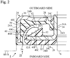
- a sealing device 20 that seals a gap between the outer race 8 and the hub 4 is located close to the end of the outer race 8 on the outboard side, and inside the end of the outer race 8 on the inboard side.
- Another sealing device 21 that seals a gap between the outer race 8 and the inner race 6 is located inside the end of the inner side of the outer race 8.
- the sealing devices 20 and 21 prevent outflow of a lubricant in the form of grease from the inside of the hub bearing 1, and prevent entry of foreign matter (water, including muddy water or salt water) into the interior of the hub bearing 1 from the outside.
- arrows F indicate an example direction of an exterior flow of foreign matter.
- the sealing device 21 is provided in a gap between the end portion 8B on the inboard side of the outer race 8 of the hub bearing 1 and the inner race 6 of the hub bearing 1.
- the sealing device 21 is annular in shape. In Fig. 2 only the left part of the sealing device 21 is shown.
- the sealing device 21 has a composite structure and includes a first sealing member 24 and a second sealing member 26.
- the first sealing member 24 is a stationary sealing member that is attached to the outer race 8 and does not rotate.
- the first sealing member 24 has a composite structure and includes an elastic ring 28 and a rigid ring 30.
- the elastic ring 28 is made of an elastic material such as an elastomer.
- the rigid ring 30 is made of a rigid material such as a metal and reinforces the elastic ring 28. As viewed in cross section, the rigid ring 30 is substantially L-shaped. A part of the rigid ring 30 is embedded in the elastic ring 28 and is in close contact with the elastic ring 28.
- the first sealing member 24 has a cylindrical part 24A, an annular part 24B, and radial lips 24C and 24D.
- the cylindrical part 24A constitutes a mounted part that is to be mounted to the outer race 8. More specifically, the cylindrical part 24A is engaged by interference fit, namely, is press-fitted into the end portion 8B of the outer race 8.
- the annular part 24B which has a circular annular shape, is located radially inside the cylindrical part 24A and extends radially inward toward the inner race 6.
- the cylindrical part 24A and the annular part 24B are formed from the rigid ring 30 and the elastic ring 28.
- the radial lips 24C and 24D extend from the inner end of the annular part 24B toward the second sealing member 26, and the distal ends of the radial lips 24C and 24D are in contact with the second sealing member 26.
- the radial lips 24C and 24D are formed from the elastic ring 28.
- the second sealing member 26 may also be referred to as a slinger, that is, a rotational sealing member.
- the second sealing member 26 is mounted to the inner race 6, rotates together with the inner race 6, and acts to deflect exterior splashing of foreign matter.
- the second sealing member 26 also has a composite structure and includes an elastic ring 32 and a rigid ring 34.
- the rigid ring 34 is made of a rigid material such as a metal.
- the flange part 34B is located radially outside the sleeve part 34A, extends radially outward, and faces the annular part 24B of the first sealing member 24.
- the flange part 34B is a flat plate and lies on a plane that is perpendicular to the axis of the sleeve part 34A.
- the elastic ring 32 is in close contact with the flange part 34B of the rigid ring 34.
- the elastic ring 32 serves to measure a rotational speed of the inner race 6.
- the elastic ring 32 is formed from an elastomer material that contains a magnetic metal powder and a ceramic powder, and has a large number of S poles and N poles provided by the magnetic metal powder.
- the S poles and N poles are alternately arranged at equiangular intervals in a circumferential direction.
- the angle of rotation of the elastic ring 32 is measured by use of a magnetic rotary encoder (not shown). Since the material of the elastic ring 32 contains a metal powder, it has a higher degree of hardness than that of conventional elastomer materials and thus is not readily susceptible to damage by foreign matter.
- the radial lip 24C of the first sealing member 24 is a grease lip that extends radially inward from the inner end of the annular part 24B.
- the grease lip 24C extends toward the sleeve part 34A of the second sealing member 26, and the distal end of the grease lip 24C is in contact with the sleeve part 34A.
- the grease lip 24C extends radially inward toward the outboard side, and has a primary role in preventing outflow of the lubricant from the inside of the hub bearing 1.
- the radial lip 24D is a dust lip that extends laterally from the inner end of the annular part 24B.
- the dust lip 24D extends radially outward toward the inboard side.
- the dust lip 24D also extends toward the sleeve part 34A of the second sealing member 26, and the distal end of the dust lip 24D is in contact with the sleeve part 34A.
- the dust lip 24D has a primary role in preventing exterior inflow of foreign matter into the hub bearing 1.
- An annular clearance 36 is provided between the distal end on the inboard side of the cylindrical part 24A of the first sealing member 24 and the outer end edge of the second sealing member 26. Foreign matter may enter through the clearance 36 into a space 42 between the annular part 24B of the first sealing member 24 and the flange part 34B of the second sealing member 26. However, foreign matter that does enter into the space 42 can also be discharged through the clearance 36.
- the water-discharge protrusions 40 protrude toward the annular part 24B of the first sealing member 24, and are supported by the second sealing member 26.
- the water-discharge protrusions 40 are of the same shape and size, and are arranged at equiangular intervals in a circumferential direction. As shown in Fig. 2 , the water-discharge protrusions 40 protrude from the inclined surface 52A of the circular protrusion 52 into the space 42 between the annular part 24B of the first sealing member 24 and the flange part 34B of the second sealing member 26.
- the water-discharge protrusions 40 each has a substantially rhombic outline that is defined by an inner arc surface 40A, an outer arc line 40B, and two inclined side surfaces 40C and 40D.
- the outer arc line 40B substantially coincides with the outer peripheral contour of the elastic ring 32 that covers the outer peripheral contour of the rigid ring 34 in the second sealing member 26.
- the elastic ring 28 of the first sealing member 24 has a curved surface 50 that extends from the cylindrical part 24A to the annular part 24B.
- the curved surface 50 has an arc shape such that the more radially inward a position is of the curved surface 50, the more distant the position is from the flange part 34B of the second sealing member 26.
- the curved surface 40G of the water-discharge protrusions 40 faces the curved surface 50 of the first sealing member 24, and is formed substantially parallel to the curved surface 50.
- the curved surface 50 defines a narrow space 42 in which the water-discharge protrusions 40 having the curved surface 40G rotate.
- the water-discharge protrusions 40 that protrude into the space 42 each has an inclined side surface 40C that intersects at an acute angle with the rotational direction R1 of the inner race 6 (see Fig. 3 ).
- the water in the space 42 flows along the inclined side surface 40C, as depicted by arrows f1 in Fig.
- the sealing device 21 has a superior ability to seal and protect the hub bearing 1 from water. Furthermore, deterioration of the sealing device 21, which would otherwise occur in the presence of water (including muddy water or salt water), is greatly reduced. Since the clearance 36 is annular, water flows out of the space 42 through one part the clearance 36, whereas air outside the sealing device 21 flows into the space 42 through another part of the clearance 36.
- Air flow into the space 42 promotes outflow of water from the space 42.
- the water-discharge protrusions 40 protrude into the space 42 that is in communication with the atmosphere. This configuration also reduces a likelihood of a negative pressure occurring in the space 42 with a resultant unexpected deformation of the lips 24C and 24D.
- the sealing device 21 since the sealing device 21 has a superior ability to discharge water due to provision of the water-discharge protrusions 40, the first sealing member 24 does not have a portion that is in contact with the flange part 34B of the second sealing member 26, for example, an axial lip to prevent entry of foreign matter. As a result, it is possible to eliminate torque that would otherwise be generated by sliding of the portion of the first sealing member 24 against the second sealing member 26, and thereby improve an energy efficiency of an automotive vehicle.
- the water-discharge protrusions 40 are each located distant from the cylindrical part 24A and the annular part 24B of the first sealing member 24. Accordingly, when the inner race 6 rotates, the water-discharge protrusions 40 do not collide with or slide against the first sealing member 24.
- the first sealing member 24 has a curved surface 50, and the water-discharge protrusions 40 each has a curved surface 40G that faces the curved surface 50. Since the first sealing member 24 and the water-discharge protrusions 40 are respectively provided with the curved surface 50 and 40G, there is little likelihood of entry of foreign matter into the space 42 between the annular part 24B and the flange part 34B from the outside.
- the first sealing member 24 has an annular circular protrusion 52, and the water-discharge protrusions 40 protrude from the inclined surface 52A of the circular protrusion 52. Accordingly, the shape of the space 42 between the annular part 24B and the flange part 34B is relatively complex, which helps prevent entry of foreign matter into the space 42 from the outside.
- a centrifugal force CF acts on air in the space 42.
- the top surface 40E of each of the water-discharge protrusions 40 is arranged perpendicular to the axial direction of the sealing device 21, and an adhesive force AF acts in an axial direction on water drops WD adhering to the top surface 40E.
- the adhesive force AF is caused by surface tension or a cohesive force of water and acts in a direction normal to the surface with which the water is in contact, thereby causing the water to adhere to the surface.
- the water drops WD adhering to the top surface 40E are moved radially outward, for example, toward the curved surface 40G under action of the resultant force of the centrifugal force CF, the adhesive force AF, and the gravitational force.
- the curved surface 40G is inclined relative to the axial direction of the sealing device 21, and the adhesive force AF acts on the water drops WD adhering to the curved surface 40G in a direction normal to the curved surface 40G.
- the water drops WD adhering to the curved surface 40G are moved radially outward, namely, toward the annular clearance 36 under action of the resultant force of the centrifugal force CF, the adhesive force AF, and the gravitational force.
- the water drops WD adhering to the curved surface 40G are moved toward the clearance 36 by the axial direction component A1 of the adhesive force AF.
- the curved surface 40G promotes water discharge.
- This effect can also be achieved by providing the water-discharge protrusions 40 with an inclined surface, instead of the curved surface 40G, with the inclined surface being inclined such that the more radially inward a position is of the inclined surface, the more distant the position is from the flange part 34B.
- the inclined surface 52A of the circular protrusion 52 is inclined with respect to the axial direction of the sealing device 21, and an adhesive force AF is exerted on water drops WD adhering to the inclined surface 52A along the normal direction of the inclined surface 52A.
- the water drops WD adhering to the inclined surface 52A are moved radially outward, i.e., toward the annular clearance 36 under action of the resultant force of the centrifugal force CF, the adhesive force AF, and the gravitational force.
- the water drops WD adhering to the inclined surface 52A are moved toward the clearance 36 by the axial direction component A1 of the adhesion force AF. In this way, the inclined surface 52A promotes water discharge.
- the water drops WD fall under the gravitational force onto the curved surface 50 of the first sealing member 24 through the outer peripheral surface of the sleeve part 34A or radial lip 24D.
- the more radially outward a position is of the curved surface 50 the closer the position is to the flange part 34B.
- the water drops WD are able to be rapidly discharged from the annular clearance 36.
- This effect can also be achieved by providing the first sealing member 24 with an inclined surface, instead of the curved surface 50, the inclined surface being inclined such that the more radially inward a position is of the inclined surface, the more distant the position is from the flange part 34B.
- a length of each of the water-discharge protrusions 40 in the rotational direction of the inner race 6 is greater than a length of each of the water-discharge protrusions 40 in radial directions of the first sealing member 24 and the second sealing member 26.
- the water-discharge protrusions 40 each has a maximum length (the length between the apex formed by the inner arc surface 40A and the inclined side surface 40C and the apex formed by the outer arc line 40B and the inclined side surface 40D) along the rotational direction R1 of the second sealing member 26 (rotational direction of the inner race 6).
- the entirety of the water-discharge protrusions 40 does not deteriorate in a short period of time. Consequently, the water-discharge protrusions 40 have a long service life.
- the water-discharge protrusions 40 protrude into the space 42 between the annular part 24B of the first sealing member 24 and the flange part 34B of the second sealing member 26.
- the water-discharge protrusions 40 are arranged in a range that is within a maximum diameter of the first sealing member 24. As a result of this arrangement, there is no need to increase a size of the sealing device 21 or the hub bearing 1.
- the water-discharge protrusions 40 are formed from the same material as that of the elastic ring 32, namely, an elastomer material containing a magnetic metal powder and a ceramic powder. Since the water-discharge protrusions 40 contain the metal powder and the ceramic powder, they have superior durability against impact of hard foreign matter and a superior wear resistance.
- the water-discharge protrusions 40 are mounted to be integral with the elastic ring 32 that covers the flange part 34B of the rigid ring 34 of the second sealing member 26. Since the number of parts used is thereby reduced, assembly of the sealing device 21 is simplified.
- a method used for forming the water-discharge protrusions 40 may be, for example, mold pressing or injection molding. By use of such a method, the water-discharge protrusions 40 can be formed simultaneously with the elastic ring 32. Alternatively, the water-discharge protrusions 40 may be joined to the flange part 34B by bonding with an adhesive, or may be formed by making cuts in the elastic ring 32.
- Fig. 8 is a cross-sectional view showing a second sealing member 26 of a sealing device 21 according to a second embodiment of the present invention.
- the sealing device 21 according to the second embodiment has a first sealing member 24, which is the same as that in the first embodiment, and a second sealing member 26, which differs in detail from that in the first embodiment.
- the front view of the second sealing member 26 is similar to that in Fig. 3 , and illustration thereof is omitted.
- Fig. 9 corresponds to a cross-sectional view taken along line IV-IV in Fig. 3 .
- Fig. 8 correspond to a cross-sectional view of the sealing device 21 taken along line II-II in Fig. 3 .
- the circular protrusion 52 supported by the second sealing member 26 includes an inner inclined surface 52B disposed radially inside the inclined surface 52A of the circular protrusion 52.
- the inner inclined surface 52B is inclined such that the more radially inward a position is of the inner inclined surface 52B, the closer the position is to the flange part 34B of the second sealing member 26.
- the second embodiment achieves the same effect as that of the first embodiment.
- the effect of discharging water upon rotation of the second sealing member 26 is also achieved in the second embodiment.
- the inner inclined surface 52B is formed radially inside the inclined surface 52A of the circular protrusion 52.
- the inner inclined surface 52B is inclined such that the more radially inward a position is of the inner inclined surface 52B, the closer the position is to the flange part 34B of the second sealing member 26, thereby enabling water drops to readily flow out of the space 42 upon rotation of the rotatable member.
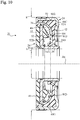
- Fig. 10 which is similar to Fig. 7 , shows advantages of the sealing device according to the second embodiment upon stop of rotation of the second sealing member.
- Fig. 10 above the central axis Ax of the sealing device 21, water drops WD flow down through the inner inclined surface 52B and readily separate from the circular protrusion 52.
- a considerable amount of water drops WD fall on the inner inclined surface 52B of the circular protrusion 52, flow down through the inner inclined surface 52B, and fall on the curved surface 50 of the first sealing member 24.
- Fig. 11 is a front view showing a second sealing member 26 of a sealing device 21 according to a third embodiment of the present invention.
- the third embodiment is a modification of the first embodiment; the second embodiment may be similarly modified.
- each of water-discharge protrusions 55 provided on the flange part 34B of the second sealing member 26 has a substantially trapezoidal outline as viewed along the axial direction of the second sealing member 26. More specifically, the water-discharge protrusions 55 each has a substantially trapezoidal outline defined by an inner arc surface 55A, an outer arc line 55B, and two inclined side surfaces 55C and 55D. The lengths of the two inclined side surfaces 55C and 55D are equal. However, the outer arc line 55B may be omitted, and the outline of each of the water-discharge protrusions 55 may be an isosceles triangle.
- the top surface 55E, the curved surface 55G, and the bottom surface (not shown) of the water-discharge protrusions 55 may be the same as the top surface 40E, the curved surface 40G, and the bottom surface 40F of the first embodiment (see Figs. 2 and 4 ).
- each of the water-discharge protrusions 55 has two inclined side surfaces 55C and 55D that intersect at acute angles with the two rotational directions R1 and R2 of the inner race 6 and the second sealing member 26.
- arrow R1 indicates the rotational direction of the second sealing member 26 (rotational direction of the inner race 6) upon forward movement of the automotive vehicle provided with the hub bearing 1.
- Arrow R2 indicates the rotational direction of the second sealing member 26 (rotational direction of the inner race 6) upon rearward movement of the automotive vehicle provided with the hub bearing 1.
- the inner arc surface 55A and the outer arc line 55B extend in arc shapes along the rotational directions R1 and R2.
- each of the inner arc surface 55A and the outer arc line 55B overlaps a circle (not shown) that is concentric with the sleeve part 34A.
- the inclined side surface 55C intersects with the rotational direction R1 at an acute angle, and intersects with the rotational direction R2 at an obtuse angle.
- the inclined side surface 55D intersects with the rotational direction R1 at an obtuse angle, and intersects with the rotational direction R2 at an acute angle.
- the water in the space 42 flows along the inclined side surface 55C, as depicted by arrows f1 in Fig. 11 , in an opposing direction to the rotational direction R1 of the inner race 6 and the second sealing member 26, relative to the rotation of the second sealing member 26.
- Intersection of the inclined side surface 55C at an acute angle with the rotational direction R1 promotes smooth flow of water.
- the water in the space 42 flows along the inclined side surface 55D, as depicted by arrows f2 in Fig.
- the sealing device 21 has a superior ability to seal and protect the hub bearing 1 from water. Furthermore, deterioration of the sealing device 21, which would otherwise occur in the presence of water (including muddy water or salt water), is greatly reduced.
- the sealing device 21 according to this modification can be used for both left and right wheels of an automotive vehicle; and due to the provision of water-discharge protrusions 50 is able to discharge water upon either forward or rearward movement of the automotive vehicle.
- a mechanic is not required to exercise particular care in selecting a wheel for mounting the sealing device.
- a length of each of the water-discharge protrusions 55 in the rotational directions R1 and R2 is greater than a length each of the water-discharge protrusions 55 in radial directions of the sealing device 21 (namely, the distance between the arc surfaces 55A and 55B). Therefore, even if hard foreign matter collides with and damages the water-discharge protrusions 55, or the water-discharge protrusions 55 are worn by water flow, the entirety of the water-discharge protrusions 55 does not deteriorate in a short period of time. Consequently, the water-discharge protrusions 55 have a long service life.
- the first to third embodiments described above relate to the sealing device 21 on the inboard side of the hub bearing 1.
- Afourth embodiment of the present invention relates to a sealing structure that includes the sealing device 20 on the outboard side of the hub bearing 1.
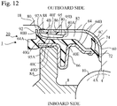
- the sealing device (sealing member) 20 is located in a gap between the end portion 8A on the outboard side of the outer race 8 of the hub bearing 1 and the hub 4 of the hub bearing 1.
- the hub 4 has an outer peripheral surface 4A of a cylindrical part in the vicinity of the balls 10, a flange surface 4B that extends radially outward from the outer peripheral surface 4A of the hub 4, and an arc surface 4C that connects the outer peripheral surface 4A and the flange surface 4B.
- the flange surface 4B is a surface on the inboard side of the outboard side flange 18.
- a rotational sealing member 60 which rotates with the hub 4, is fixed to the periphery of the hub 4, although the sealing member 60 is not absolutely necessary.
- the rotational sealing member 60 is made of a rigid material such as a metal.
- the sealing device 20 and the rotational sealing member 60 each have an annular shape. In Fig. 12 , only the left parts of the sealing device and the sealing member are shown.
- the sealing device 20 has a composite structure and includes an elastic ring 64 and a rigid ring 66.
- the elastic ring 64 is made of an elastic material such as an elastomer.
- the rigid ring 66 is made of a rigid material, for example, a metal, and reinforces the elastic ring 64.
- a part of the rigid ring 66 is embedded in the elastic ring 64 and is in close contact with the elastic ring 64.
- a part of the rigid ring 66 having a U-shaped cross section is engaged by interference fit, namely, is press-fitted into the inner peripheral surface of the end portion 8 of the outer race 8A.
- the elastic ring 64 has an annular part 64A, an inclined connecting part 64B, and lips 72 and 74.
- the annular part 64A which has a circular annular shape, is in contact with the end surface of the end portion 8A of the outer race 8, and extends radially inward toward the outer peripheral surface 4A of the cylindrical part of the hub 4 so as to be orthogonal to the central axis Ax of the hub bearing 1.
- the annular part 64A faces the flange surface 4B of the outboard side flange 18.
- the inclined connecting part 64B is located radially inside the annular part 64A.
- the inclined connecting part 64B extends obliquely from the annular part 64A radially inward and toward the inboard side, is bent orthogonal to the central axis Ax of the hub bearing 1, and extends further inwardly in radial directions.
- the lips 72 and 74 extend from the inclined connecting part 64B toward the hub 4 of the hub bearing 1.
- Each of the lips 72 and 74 is made of an elastic material only, and is an annular ring composed by a thin plate that extends from the inclined connecting part 64B. The distal end of each of the lips 72 and 74 is brought into contact with the rotational sealing member 60.
- the sealing device 20 is attached to the stationary outer race 8, but since the hub 4 rotates the lips 72 and 74 slide on the rotational sealing member 60 fixed to the hub 4.
- the lip 72 is a radial lip, that is, a grease lip, and extends from the innermost edge of the inclined connecting part 64B toward the cylindrical part of the hub 4 near the balls 10.
- the distal end of the radial lip 72 is to be in contact with a portion of the rotational sealing member 60 that covers the outer peripheral surface 4A of the cylindrical part.
- the radial lip 72 extends radially inward and toward the inboard side, and has a primary role in preventing outflow of the lubricant from the inside of the hub bearing 1.
- the lip 74 extends laterally from the inclined connecting part 64B.
- the lip 74 is an axial lip, that is, a side lip, and extends toward the arc surface 4C of the hub 4.
- the distal end of the axial lip 74 is in contact with a part of the rotational sealing member 60 that covers the arc surface 4C of the hub 4.
- the lip 74 is a dust lip and has a primary role in preventing exterior inflow of foreign matter into the hub bearing 1.
- annular clearance 80 is provided between the end portion 8A of the outer race 8 and the flange surface 4B of the hub 4. Foreign matter may enter into a space 82 through the clearance 80 between the annular part 64A of the sealing device 20 and the flange surface 4B of the second sealing member 26 (in this embodiment, the space between the annular part 64A and the rotational sealing member 60). However, foreign matter that does enter into the space 82 can also be discharged through the clearance 80.
- an annular circular protrusion 95 and water-discharge protrusions 40 protruding toward the annular part 64A of the sealing device 20 are supported on the outboard side flange 18 of the hub 4.
- the circular protrusion 95 is substantially triangular in shape.
- the circular protrusion 95 has an inclined surface 95A, such that the more radially inward a position of the inclined surface 95A, the more distant the position is from the flange surface 4B flange part 34B of the hub 4.
- the circular protrusion 95 includes an inner inclined surface 95B disposed radially inside the inclined surface 95A of the circular protrusion 95.
- the inner inclined surface 95B is inclined such that the more radially inward a position of the inner inclined surface 95B, the closer the position is to the flange surface 4B of the hub 4.
- the water-discharge protrusions 40 are of the same shape and size, and are arranged at equiangular intervals in the circumferential direction.
- the water-discharge protrusions 40 protrude into the space 82.
- the circular protrusion 95 and the water-discharge protrusions 40 are mounted to be integral with an elastic ring 86 that is attached to the outboard side flange 18.
- the circular protrusion 95, the water-discharge protrusions 40, and the elastic ring 86 are each made of an elastic material, for example, an elastomer material.
- the circular protrusion 95, the water-discharge protrusions 40, and the elastic ring 86 may be formed from a resin material, an elastomer material, a resin material containing at least one of a metal powder and a ceramic powder, or an elastomer material containing at least one of a metal powder and a ceramic powder.
- the circular protrusion 95, the water-discharge protrusions 40, and the elastic ring 86 contain at least one of the metal powder and the ceramic powder, the circular protrusion 95, the water-discharge protrusions 40, and the elastic ring 86 have superior durability against the impact of hard foreign matter and a superior wear resistance.
- the elastic ring 86 covers the outer edge of the rotational sealing member 60 and further covers a part of the surface of the rotational sealing member 60 on the side of the flange surface 4B.
- An annular seal protrusion 88 is formed on this part of the elastic ring 86.
- the annular seal protrusion 88 is sandwiched between the rotational sealing member 60 and the flange surface 4B, and prevents or reduces contact of water with the flange surface 4B, thereby suppressing rusting of the hub 4.
- the water-discharge protrusions 40 of this embodiment may be the same as the water-discharge protrusions 40 or 55 of the first to third embodiments.
- reference numerals used to denote the water-discharge protrusions 40 of the first embodiment are used in Fig. 12 .
- the bottom surface 40F of each of the water-discharge protrusions 40 lies on the same plane as the surface of the elastic ring 86, whereas the top surface 40E is parallel to the flange surface 4B.
- the curved surface 40G is curved in an arc shape such that the more radially inward a position is on the curved surface 65G, the more distant the position is from the flange surface 4B.
- the sealing device 20 has an annular outer labyrinth lip 92.
- the outer labyrinth lip 92 protrudes from the annular part 64A of the elastic ring 64 toward the outboard side flange 18 of the hub 4, but is not in contact with either the hub 4 or the rotational sealing member 60.
- the outer labyrinth lip 92 overlaps the water-discharge protrusions 40 in radial directions, and is disposed radially outside the water-discharge protrusions 40.
- the outer labyrinth lip 92 has a curved surface 92A such that the more radially inward the position is of the outer labyrinth lip 192, the more distant the position is from the flange surface 4B.
- the curved surface 40G of each of the water-discharge protrusions 40 faces the curved surface 92 of the outer labyrinth lip 92A, and is formed substantially parallel to the curved surface 92A.
- the curved surface 92A defines a narrow space 82 in which the water-discharge protrusions 40 having the curved surface 40G rotate.
- each of the water-discharge protrusions 40 may be provided with an inclined surface that is inclined such that the more radially inward a position of the inclined surface, the more distant the position is from the flange surface 4B.
- the outer labyrinth lip 92 may have an inclined surface such that the more radially inward a position is of the inclined surface of the outer labyrinth lip 192, the more distant the position is from the flange surface 4B; the inclined surface of the outer labyrinth lip 192 is substantially parallel to the inclined surface of each of the water-discharge protrusions 40.
- Fig. 3 which was referred to in relation to the first embodiment, is again referred to.
- the second sealing member 26 can be viewed as the rotational sealing member 60.
- Arrow R1 can be considered as the rotational direction of the hub 4 upon forward movement of the automotive vehicle provided with the hub bearing 1.
- the inclined side surface 40C intersects with the rotational direction R1 of the hub 4 at an acute angle, whereas the inclined side surface 40D intersects with the rotational direction R1 at an obtuse angle.
- each of the water-discharge protrusions 40 protrude into the space 82, and each of the water-discharge protrusions 40 has an inclined side surface 40C that intersects at an acute angle with the rotational direction R1 of the hub 4 (see Fig. 3 ). Accordingly, as the hub 4 rotates, water in the space 82 flows along the inclined side surface 40C in a direction opposite to the rotational direction R1 of the hub 4 relative to the rotation of the hub 4. Intersection of the inclined side surface 40C with the rotational direction R1 at an acute angle promotes smooth flow of water.
- the sealing structure has a superior ability to seal and protect the hub bearing 1 from water. Furthermore, deterioration of the sealing device 20, that would otherwise occur in the presence of water (including muddy water or salt water), is greatly reduced. Since the clearance 80 is annular, water flows out of the space 82 through one part of the clearance 80, whereas air from outside the sealing device 20 flows into the space 82 through another part of the clearance 80. Air flow into the space 82 promotes outflow of water from the space 82. In other words, it is preferable that the water-discharge protrusions 40 protrude into the space 82 that is in communication with the atmosphere. This configuration also reduces a likelihood of a negative pressure occurring in the space 82 with a resultant unexpected deformation of the lips 74 and 76.
- the sealing structure Due to provision of the water-discharge protrusions 40, the sealing structure has a superior ability to discharge water, and thus there is no need increase a number of dust lips 74 to prevent entry of foreign matter, and there is also no need to increase a contact pressure of the lips 72 and 74 against the rotational sealing member 60. As a result, it is possible to suppress or reduce a torque generated by sliding of the lips 72 and 74 on the rotational sealing member 60, while improving an ability to discharge water.
- the water-discharge protrusions 40 are each located distant from the annular part 64A of the sealing device 20. Accordingly, when the hub 4 rotates, the water-discharge protrusions 40 do not collide with or slide against the sealing device 20.
- the outer labyrinth discharge 92 has a curved surface 92A
- the water-discharge protrusions 40 each has a curved surface 40G facing the curved surface 92A. Since the outer labyrinth lip 92 and the water-discharge protrusions 40 are respectively provided with the curved surface 92A and 40G, there is little likelihood of entry of foreign matter into the space 82 from the outside.
- the more radially outward a position is of the curved surface 40G of the water-discharge protrusions 40 the closer the position is to the flange surface 4B. Accordingly, an ability to discharge water is high.
- the more radially outward a position is of the inclined surface 95A of the circular protrusion 95 the closer the position is to the flange surface 4B. Accordingly, an ability to discharge water is also high. This effect is obtained for the same reasons as those described in the first embodiment with reference to Fig. 6 .
- the more radially inward a position is of the inner inclined surface 95B the closer the position is to the flange surface 4B. Accordingly, water drops are able to readily flow out of the space 42 upon rotation of the rotating member.
- a length of each of the water-discharge protrusions 40 in the direction of rotation of the hub 4 is greater than that of each of the water-discharge protrusions 40 in radial directions of the sealing device 20.
- the water-discharge protrusions 40 each has a maximum length (the length between the apex formed by the inner arc surface 40A and the inclined side surface 40C and the apex formed by the outer arc line 40B and the inclined side surface 40D) along the rotational direction R1 of the hub 4.
- the entirety of the water-discharge protrusions 40 does not deteriorate in a short period of time. Consequently, the water-discharge protrusions 40 have a long service life.
- the water-discharge protrusions 40 protrude into the space 82 between the annular part 64A of the sealing device 20 and the outboard side flange 18 of the hub 4.
- the water-discharge protrusions 40 are arranged in a range that is within a maximum diameter of the sealing device 20. As a result of this arrangement, there is no need to increase a size of the sealing structure or the hub bearing 1.
- water-discharge protrusions 40 instead of the water-discharge protrusions 40, water-discharge protrusions 55 suitable for rotation of the hub 4 in both a forward and rearward direction may be supported by the outboard side flange 18.
- the rotational sealing member 60 is fixed around the hub 4.
- the rotational sealing member 60 may be omitted so that the lips 72 and 74 are in contact with the hub 4.
- the water-discharge protrusions 40 may be directly mounted to be integral with the outboard side flange 18 of the sealing device 20.
- the water-discharge protrusions 40 may be formed of the same rigid material as that used for the outboard side flange 18, for example, a metal.
- the hub 4 and the inner race 6, which are inner members are rotatable members, while the outer race 8, which is an outer member, is a stationary member.
- the present invention is not limited thereto, and may be configured such that multiple sealed members rotate relative to each other.
- inner members may be stationary while an outer member may be rotatable, or all of the members may be rotatable.
- the present invention is not limited to sealing the hub bearing 1.
- the sealing device or the sealing structure according to the present invention may be applied to a differential gear mechanism or other power transmission mechanism of an automotive vehicle, to a bearing or other support mechanism for a drive shaft of an automotive vehicle, or to a bearing or other support mechanism of a rotary shaft of a pump.
- the rigid ring 30 of the sealing device 21 in the first to third embodiments consists of a single component
- the rigid ring 30 of the sealing device 21 in the first to third embodiments may be employed multiple rigid rings that are provided radially apart from each other.
- the rigid ring 66 of the sealing device 20 of the fourth embodiment also consists of a single component. However, in place of the rigid ring 66, there may be employed multiple rigid rings that are provided radially apart from each other.
- the second sealing member further includes a cylindrical sleeve part that surrounds the inner member, and wherein the first sealing member includes two radial lips formed from an elastic material and that extend toward the sleeve part of the second sealing member.
- the radial lips serve to reliably enhance prevention of intrusion of foreign matter.
- the radial lips serve to reliably enhance prevention of intrusion of foreign matter.
- first sealing member includes a curved surface or an inclined surface, such that the more radially inward a position is of the curved surface or the inclined surface, the more distant the position is from the flange part of the second sealing member, each of the water-discharge protrusions including a curved surface or an inclined surface, such that the more radially inward a position is of the curved surface or the inclined surface, the more distant the position is from the flange part of the second sealing member, the curved surface or the inclined surface of the water-discharge protrusions facing the curved surface or the inclined surface of the first sealing member.
- each of the first sealing member and the water-discharge protrusions include either the curved surface or the inclined surface, there is little likelihood of entry of foreign matter into the space between the annular part and the flange part from the outside. Moreover, the more radially outward a position is of the curved surface or the inclined surface of the water-discharge protrusions, the closer the position is to the flange part. Accordingly, an ability to discharge water is high.
- water drops are able to readily flow out of the space both upon start of rotation of the rotating member and upon stop of rotation of the rotating member.
- each of the water-discharge protrusions includes two inclined side surfaces that intersect at an acute angle with two rotational directions in which at least one of the inner member and the outer member respectively rotates.
- each of the inclined side surfaces promotes smooth flow of water in either of the rotational directions.
- the sealing device can be used in either of the rotational directions.
- air flow into the space promotes outflow of water from the space.
- the sealing device according to any one of Clauses 1 to 8, wherein the water-discharge protrusions are formed from a resin material, an elastomer material, a resin material containing at least one of a metal powder and a ceramic powder, an elastomer material containing at least one of a metal powder and a ceramic powder, or a metal.
- the water-discharge protrusions contain at least one of a metal powder and a ceramic powder, or are formed from a metal
- the water-discharge protrusions have superior durability against impact of hard foreign matter and a superior wear resistance.
- the water-discharge protrusions protrude into the space between the annular part of the sealing member and the flange of the inner member, there is no need to enlarge the sealing structure to accommodate the water-discharge protrusions. Since the water-discharge protrusions protrude from the inclined surface of the circular protrusion supported by the inner member, there is little likelihood of entry of foreign matter into the space between the annular part and the flange from the outside. Moreover, the more radially outward the position is of the inclined surface of the circular protrusion, the closer the position is to the flange. Accordingly, an ability to discharge water is high.
Landscapes
- Engineering & Computer Science (AREA)
- General Engineering & Computer Science (AREA)
- Mechanical Engineering (AREA)
- Physics & Mathematics (AREA)
- Fluid Mechanics (AREA)
- Sealing Of Bearings (AREA)
- Rolling Contact Bearings (AREA)
- Sealing With Elastic Sealing Lips (AREA)
- Sealing Using Fluids, Sealing Without Contact, And Removal Of Oil (AREA)
- Sealing Devices (AREA)
Applications Claiming Priority (2)
| Application Number | Priority Date | Filing Date | Title |
|---|---|---|---|
| JP2018159414 | 2018-08-28 | ||
| PCT/JP2019/031762 WO2020045073A1 (fr) | 2018-08-28 | 2019-08-09 | Dispositif d'étanchéité |
Publications (2)
| Publication Number | Publication Date |
|---|---|
| EP3845785A1 true EP3845785A1 (fr) | 2021-07-07 |
| EP3845785A4 EP3845785A4 (fr) | 2021-11-03 |
Family
ID=69644918
Family Applications (1)
| Application Number | Title | Priority Date | Filing Date |
|---|---|---|---|
| EP19855101.2A Withdrawn EP3845785A4 (fr) | 2018-08-28 | 2019-08-09 | Dispositif d'étanchéité |
Country Status (5)
| Country | Link |
|---|---|
| US (1) | US20210115973A1 (fr) |
| EP (1) | EP3845785A4 (fr) |
| JP (1) | JPWO2020045073A1 (fr) |
| CN (1) | CN112437853A (fr) |
| WO (1) | WO2020045073A1 (fr) |
Families Citing this family (3)
| Publication number | Priority date | Publication date | Assignee | Title |
|---|---|---|---|---|
| JP7582835B2 (ja) * | 2020-10-23 | 2024-11-13 | 株式会社Subaru | 密封装置 |
| JP7651491B2 (ja) * | 2022-02-14 | 2025-03-26 | 株式会社シマノ | 人力駆動車用のドライブユニット |
| JP2024103285A (ja) * | 2023-01-20 | 2024-08-01 | 内山工業株式会社 | 密封装置 |
Family Cites Families (15)
| Publication number | Priority date | Publication date | Assignee | Title |
|---|---|---|---|---|
| JPS4512494Y1 (fr) * | 1965-03-24 | 1970-06-01 | ||
| JPH0729343Y2 (ja) * | 1989-12-21 | 1995-07-05 | 内山工業株式会社 | シール装置 |
| JP3991200B2 (ja) | 2002-03-05 | 2007-10-17 | Nok株式会社 | 密封装置 |
| WO2009130933A1 (fr) * | 2008-04-25 | 2009-10-29 | Nok株式会社 | Dispositif d’étanchéité |
| JP2010180896A (ja) * | 2009-02-03 | 2010-08-19 | Ntn Corp | 車輪用軸受シールおよびこれを備えた車輪用軸受装置 |
| JP2012207769A (ja) * | 2011-03-30 | 2012-10-25 | Ntn Corp | 車輪用軸受装置 |
| JP2013234748A (ja) * | 2012-05-11 | 2013-11-21 | Uchiyama Manufacturing Corp | 密封構造 |
| JP2015068350A (ja) * | 2013-09-26 | 2015-04-13 | Ntn株式会社 | 車輪用軸受シール |
| JP6253188B2 (ja) * | 2013-11-01 | 2017-12-27 | 内山工業株式会社 | 軸受密封装置 |
| JP6439262B2 (ja) * | 2014-03-19 | 2018-12-19 | 日本精工株式会社 | 転がり軸受 |
| ITUB20160770A1 (it) * | 2015-02-17 | 2017-08-16 | Skf Ab | Complesso di tenuta per cuscinetti di rotolamento, in particolare per unità mozzo ruota di veicoli ed unità mozzo ruota associata. |
| JP6603078B2 (ja) * | 2015-08-31 | 2019-11-06 | Ntn株式会社 | 車輪用軸受装置 |
| JP6717524B2 (ja) * | 2015-09-16 | 2020-07-01 | Ntn株式会社 | 車輪用軸受装置 |
| JP6771739B2 (ja) * | 2016-06-14 | 2020-10-21 | Nok株式会社 | 密封構造 |
| EP3763974A4 (fr) * | 2018-03-08 | 2021-04-07 | NOK Corporation | Dispositif d'étanchéité et structure d'étanchéité |
-
2019
- 2019-08-09 EP EP19855101.2A patent/EP3845785A4/fr not_active Withdrawn
- 2019-08-09 US US17/257,092 patent/US20210115973A1/en not_active Abandoned
- 2019-08-09 CN CN201980047956.8A patent/CN112437853A/zh active Pending
- 2019-08-09 JP JP2020539318A patent/JPWO2020045073A1/ja active Pending
- 2019-08-09 WO PCT/JP2019/031762 patent/WO2020045073A1/fr not_active Ceased
Also Published As
| Publication number | Publication date |
|---|---|
| JPWO2020045073A1 (ja) | 2021-08-10 |
| US20210115973A1 (en) | 2021-04-22 |
| WO2020045073A1 (fr) | 2020-03-05 |
| CN112437853A (zh) | 2021-03-02 |
| EP3845785A4 (fr) | 2021-11-03 |
Similar Documents
| Publication | Publication Date | Title |
|---|---|---|
| CN113939663B (zh) | 密封装置 | |
| CN110088492B (zh) | 密封装置 | |
| CN114514383B (zh) | 密封装置 | |
| US20210115973A1 (en) | Sealing device | |
| US20200386317A1 (en) | Sealing device and sealing structure | |
| EP3845782A1 (fr) | Procédé de fabrication d'un élément d'étanchéité et moule de moulage | |
| EP3845786A1 (fr) | Dispositif d'étanchéité | |
| JP7390131B2 (ja) | 密封装置および密封構造 | |
| EP4155564A1 (fr) | Dispositif d'étanchéité | |
| JP7341778B2 (ja) | 密封装置および密封構造 | |
| JP7344697B2 (ja) | 密封装置および密封構造 | |
| JP7175170B2 (ja) | 密封装置 | |
| JP2022156566A (ja) | 車輪用軸受装置 | |
| WO2022244839A1 (fr) | Dispositif d'étanchéité | |
| JP2020197291A (ja) | 密封装置 | |
| JP2020133739A (ja) | 密封装置 | |
| WO2023189756A1 (fr) | Dispositif de roulement de roue | |
| JP2022048883A (ja) | 密封装置 | |
| JP2020143727A (ja) | 密封装置および密封構造 | |
| JP2021017893A (ja) | 密封装置 | |
| KR20200081635A (ko) | 오일 씰 | |
| JP2017015212A (ja) | 密封装置 |
Legal Events
| Date | Code | Title | Description |
|---|---|---|---|
| STAA | Information on the status of an ep patent application or granted ep patent |
Free format text: STATUS: THE INTERNATIONAL PUBLICATION HAS BEEN MADE |
|
| STAA | Information on the status of an ep patent application or granted ep patent |
Free format text: STATUS: REQUEST FOR EXAMINATION WAS MADE |
|
| PUAI | Public reference made under article 153(3) epc to a published international application that has entered the european phase |
Free format text: ORIGINAL CODE: 0009012 |
|
| 17P | Request for examination filed |
Effective date: 20201215 |
|
| AK | Designated contracting states |
Kind code of ref document: A1 Designated state(s): AL AT BE BG CH CY CZ DE DK EE ES FI FR GB GR HR HU IE IS IT LI LT LU LV MC MK MT NL NO PL PT RO RS SE SI SK SM TR |
|
| A4 | Supplementary search report drawn up and despatched |
Effective date: 20211005 |
|
| RIC1 | Information provided on ipc code assigned before grant |
Ipc: F16J 15/3244 20160101ALI20210929BHEP Ipc: F16J 15/447 20060101ALI20210929BHEP Ipc: F16J 15/3232 20160101ALI20210929BHEP Ipc: F16C 33/78 20060101ALI20210929BHEP Ipc: F16C 19/18 20060101ALI20210929BHEP Ipc: F16J 15/44 20060101AFI20210929BHEP |
|
| STAA | Information on the status of an ep patent application or granted ep patent |
Free format text: STATUS: THE APPLICATION HAS BEEN WITHDRAWN |
|
| DAV | Request for validation of the european patent (deleted) | ||
| DAX | Request for extension of the european patent (deleted) | ||
| 18W | Application withdrawn |
Effective date: 20211123 |