EP3845788A1 - Dustproof gate valve - Google Patents
Dustproof gate valve Download PDFInfo
- Publication number
- EP3845788A1 EP3845788A1 EP20153017.7A EP20153017A EP3845788A1 EP 3845788 A1 EP3845788 A1 EP 3845788A1 EP 20153017 A EP20153017 A EP 20153017A EP 3845788 A1 EP3845788 A1 EP 3845788A1
- Authority
- EP
- European Patent Office
- Prior art keywords
- panel
- valve
- dust
- slide
- valve port
- Prior art date
- Legal status (The legal status is an assumption and is not a legal conclusion. Google has not performed a legal analysis and makes no representation as to the accuracy of the status listed.)
- Granted
Links
Images






Classifications
-
- F—MECHANICAL ENGINEERING; LIGHTING; HEATING; WEAPONS; BLASTING
- F16—ENGINEERING ELEMENTS AND UNITS; GENERAL MEASURES FOR PRODUCING AND MAINTAINING EFFECTIVE FUNCTIONING OF MACHINES OR INSTALLATIONS; THERMAL INSULATION IN GENERAL
- F16K—VALVES; TAPS; COCKS; ACTUATING-FLOATS; DEVICES FOR VENTING OR AERATING
- F16K3/00—Gate valves or sliding valves, i.e. cut-off apparatus with closing members having a sliding movement along the seat for opening and closing
- F16K3/02—Gate valves or sliding valves, i.e. cut-off apparatus with closing members having a sliding movement along the seat for opening and closing with flat sealing faces; Packings therefor
- F16K3/0227—Packings
-
- F—MECHANICAL ENGINEERING; LIGHTING; HEATING; WEAPONS; BLASTING
- F16—ENGINEERING ELEMENTS AND UNITS; GENERAL MEASURES FOR PRODUCING AND MAINTAINING EFFECTIVE FUNCTIONING OF MACHINES OR INSTALLATIONS; THERMAL INSULATION IN GENERAL
- F16K—VALVES; TAPS; COCKS; ACTUATING-FLOATS; DEVICES FOR VENTING OR AERATING
- F16K3/00—Gate valves or sliding valves, i.e. cut-off apparatus with closing members having a sliding movement along the seat for opening and closing
- F16K3/02—Gate valves or sliding valves, i.e. cut-off apparatus with closing members having a sliding movement along the seat for opening and closing with flat sealing faces; Packings therefor
-
- F—MECHANICAL ENGINEERING; LIGHTING; HEATING; WEAPONS; BLASTING
- F16—ENGINEERING ELEMENTS AND UNITS; GENERAL MEASURES FOR PRODUCING AND MAINTAINING EFFECTIVE FUNCTIONING OF MACHINES OR INSTALLATIONS; THERMAL INSULATION IN GENERAL
- F16K—VALVES; TAPS; COCKS; ACTUATING-FLOATS; DEVICES FOR VENTING OR AERATING
- F16K3/00—Gate valves or sliding valves, i.e. cut-off apparatus with closing members having a sliding movement along the seat for opening and closing
- F16K3/30—Details
- F16K3/316—Guiding of the slide
- F16K3/3165—Guiding of the slide with rollers or balls
-
- F—MECHANICAL ENGINEERING; LIGHTING; HEATING; WEAPONS; BLASTING
- F16—ENGINEERING ELEMENTS AND UNITS; GENERAL MEASURES FOR PRODUCING AND MAINTAINING EFFECTIVE FUNCTIONING OF MACHINES OR INSTALLATIONS; THERMAL INSULATION IN GENERAL
- F16K—VALVES; TAPS; COCKS; ACTUATING-FLOATS; DEVICES FOR VENTING OR AERATING
- F16K3/00—Gate valves or sliding valves, i.e. cut-off apparatus with closing members having a sliding movement along the seat for opening and closing
- F16K3/02—Gate valves or sliding valves, i.e. cut-off apparatus with closing members having a sliding movement along the seat for opening and closing with flat sealing faces; Packings therefor
- F16K3/0218—Gate valves or sliding valves, i.e. cut-off apparatus with closing members having a sliding movement along the seat for opening and closing with flat sealing faces; Packings therefor with only one sealing face
-
- F—MECHANICAL ENGINEERING; LIGHTING; HEATING; WEAPONS; BLASTING
- F16—ENGINEERING ELEMENTS AND UNITS; GENERAL MEASURES FOR PRODUCING AND MAINTAINING EFFECTIVE FUNCTIONING OF MACHINES OR INSTALLATIONS; THERMAL INSULATION IN GENERAL
- F16K—VALVES; TAPS; COCKS; ACTUATING-FLOATS; DEVICES FOR VENTING OR AERATING
- F16K3/00—Gate valves or sliding valves, i.e. cut-off apparatus with closing members having a sliding movement along the seat for opening and closing
- F16K3/02—Gate valves or sliding valves, i.e. cut-off apparatus with closing members having a sliding movement along the seat for opening and closing with flat sealing faces; Packings therefor
- F16K3/0254—Gate valves or sliding valves, i.e. cut-off apparatus with closing members having a sliding movement along the seat for opening and closing with flat sealing faces; Packings therefor being operated by particular means
-
- F—MECHANICAL ENGINEERING; LIGHTING; HEATING; WEAPONS; BLASTING
- F16—ENGINEERING ELEMENTS AND UNITS; GENERAL MEASURES FOR PRODUCING AND MAINTAINING EFFECTIVE FUNCTIONING OF MACHINES OR INSTALLATIONS; THERMAL INSULATION IN GENERAL
- F16K—VALVES; TAPS; COCKS; ACTUATING-FLOATS; DEVICES FOR VENTING OR AERATING
- F16K3/00—Gate valves or sliding valves, i.e. cut-off apparatus with closing members having a sliding movement along the seat for opening and closing
- F16K3/02—Gate valves or sliding valves, i.e. cut-off apparatus with closing members having a sliding movement along the seat for opening and closing with flat sealing faces; Packings therefor
- F16K3/0281—Guillotine or blade-type valves, e.g. no passage through the valve member
-
- F—MECHANICAL ENGINEERING; LIGHTING; HEATING; WEAPONS; BLASTING
- F16—ENGINEERING ELEMENTS AND UNITS; GENERAL MEASURES FOR PRODUCING AND MAINTAINING EFFECTIVE FUNCTIONING OF MACHINES OR INSTALLATIONS; THERMAL INSULATION IN GENERAL
- F16K—VALVES; TAPS; COCKS; ACTUATING-FLOATS; DEVICES FOR VENTING OR AERATING
- F16K3/00—Gate valves or sliding valves, i.e. cut-off apparatus with closing members having a sliding movement along the seat for opening and closing
- F16K3/02—Gate valves or sliding valves, i.e. cut-off apparatus with closing members having a sliding movement along the seat for opening and closing with flat sealing faces; Packings therefor
- F16K3/16—Gate valves or sliding valves, i.e. cut-off apparatus with closing members having a sliding movement along the seat for opening and closing with flat sealing faces; Packings therefor with special arrangements for separating the sealing faces or for pressing them together
- F16K3/18—Gate valves or sliding valves, i.e. cut-off apparatus with closing members having a sliding movement along the seat for opening and closing with flat sealing faces; Packings therefor with special arrangements for separating the sealing faces or for pressing them together by movement of the closure members
-
- F—MECHANICAL ENGINEERING; LIGHTING; HEATING; WEAPONS; BLASTING
- F16—ENGINEERING ELEMENTS AND UNITS; GENERAL MEASURES FOR PRODUCING AND MAINTAINING EFFECTIVE FUNCTIONING OF MACHINES OR INSTALLATIONS; THERMAL INSULATION IN GENERAL
- F16K—VALVES; TAPS; COCKS; ACTUATING-FLOATS; DEVICES FOR VENTING OR AERATING
- F16K3/00—Gate valves or sliding valves, i.e. cut-off apparatus with closing members having a sliding movement along the seat for opening and closing
- F16K3/02—Gate valves or sliding valves, i.e. cut-off apparatus with closing members having a sliding movement along the seat for opening and closing with flat sealing faces; Packings therefor
- F16K3/16—Gate valves or sliding valves, i.e. cut-off apparatus with closing members having a sliding movement along the seat for opening and closing with flat sealing faces; Packings therefor with special arrangements for separating the sealing faces or for pressing them together
- F16K3/18—Gate valves or sliding valves, i.e. cut-off apparatus with closing members having a sliding movement along the seat for opening and closing with flat sealing faces; Packings therefor with special arrangements for separating the sealing faces or for pressing them together by movement of the closure members
- F16K3/184—Gate valves or sliding valves, i.e. cut-off apparatus with closing members having a sliding movement along the seat for opening and closing with flat sealing faces; Packings therefor with special arrangements for separating the sealing faces or for pressing them together by movement of the closure members by means of cams
-
- F—MECHANICAL ENGINEERING; LIGHTING; HEATING; WEAPONS; BLASTING
- F16—ENGINEERING ELEMENTS AND UNITS; GENERAL MEASURES FOR PRODUCING AND MAINTAINING EFFECTIVE FUNCTIONING OF MACHINES OR INSTALLATIONS; THERMAL INSULATION IN GENERAL
- F16K—VALVES; TAPS; COCKS; ACTUATING-FLOATS; DEVICES FOR VENTING OR AERATING
- F16K3/00—Gate valves or sliding valves, i.e. cut-off apparatus with closing members having a sliding movement along the seat for opening and closing
- F16K3/30—Details
-
- F—MECHANICAL ENGINEERING; LIGHTING; HEATING; WEAPONS; BLASTING
- F16—ENGINEERING ELEMENTS AND UNITS; GENERAL MEASURES FOR PRODUCING AND MAINTAINING EFFECTIVE FUNCTIONING OF MACHINES OR INSTALLATIONS; THERMAL INSULATION IN GENERAL
- F16K—VALVES; TAPS; COCKS; ACTUATING-FLOATS; DEVICES FOR VENTING OR AERATING
- F16K3/00—Gate valves or sliding valves, i.e. cut-off apparatus with closing members having a sliding movement along the seat for opening and closing
- F16K3/30—Details
- F16K3/314—Forms or constructions of slides; Attachment of the slide to the spindle
-
- F—MECHANICAL ENGINEERING; LIGHTING; HEATING; WEAPONS; BLASTING
- F16—ENGINEERING ELEMENTS AND UNITS; GENERAL MEASURES FOR PRODUCING AND MAINTAINING EFFECTIVE FUNCTIONING OF MACHINES OR INSTALLATIONS; THERMAL INSULATION IN GENERAL
- F16K—VALVES; TAPS; COCKS; ACTUATING-FLOATS; DEVICES FOR VENTING OR AERATING
- F16K31/00—Actuating devices; Operating means; Releasing devices
- F16K31/44—Mechanical actuating means
-
- F—MECHANICAL ENGINEERING; LIGHTING; HEATING; WEAPONS; BLASTING
- F16—ENGINEERING ELEMENTS AND UNITS; GENERAL MEASURES FOR PRODUCING AND MAINTAINING EFFECTIVE FUNCTIONING OF MACHINES OR INSTALLATIONS; THERMAL INSULATION IN GENERAL
- F16K—VALVES; TAPS; COCKS; ACTUATING-FLOATS; DEVICES FOR VENTING OR AERATING
- F16K31/00—Actuating devices; Operating means; Releasing devices
- F16K31/44—Mechanical actuating means
- F16K31/52—Mechanical actuating means with crank, eccentric, or cam
- F16K31/524—Mechanical actuating means with crank, eccentric, or cam with a cam
- F16K31/52475—Mechanical actuating means with crank, eccentric, or cam with a cam comprising a sliding valve
-
- F—MECHANICAL ENGINEERING; LIGHTING; HEATING; WEAPONS; BLASTING
- F16—ENGINEERING ELEMENTS AND UNITS; GENERAL MEASURES FOR PRODUCING AND MAINTAINING EFFECTIVE FUNCTIONING OF MACHINES OR INSTALLATIONS; THERMAL INSULATION IN GENERAL
- F16K—VALVES; TAPS; COCKS; ACTUATING-FLOATS; DEVICES FOR VENTING OR AERATING
- F16K31/00—Actuating devices; Operating means; Releasing devices
- F16K31/44—Mechanical actuating means
- F16K31/52—Mechanical actuating means with crank, eccentric, or cam
- F16K31/528—Mechanical actuating means with crank, eccentric, or cam with pin and slot
- F16K31/5286—Mechanical actuating means with crank, eccentric, or cam with pin and slot comprising a sliding valve
-
- F—MECHANICAL ENGINEERING; LIGHTING; HEATING; WEAPONS; BLASTING
- F16—ENGINEERING ELEMENTS AND UNITS; GENERAL MEASURES FOR PRODUCING AND MAINTAINING EFFECTIVE FUNCTIONING OF MACHINES OR INSTALLATIONS; THERMAL INSULATION IN GENERAL
- F16K—VALVES; TAPS; COCKS; ACTUATING-FLOATS; DEVICES FOR VENTING OR AERATING
- F16K31/00—Actuating devices; Operating means; Releasing devices
- F16K31/44—Mechanical actuating means
- F16K31/60—Handles
- F16K31/602—Pivoting levers, e.g. single-sided
Definitions
- the present invention relates to gate valve technology and more particularly, to a dustproof gate valve.
- Taiwan Patent 1551798 equivalent to US 9,464,721 , discloses a gate valve with a locking function. This design mainly uses a driver to drive a swing arm, thereby moving a slide. When the slide is moved to the second locking position, the valve member at the slide blocks the valve port, thereby achieving the effect of locking the valve member when the gage valve is closed.
- the present invention has been accomplished under the circumstances in view. It is the main object of the present invention to provide a dustproof gate valve, which completely closes the valve port when it is closed, and uses a dust pipe to shield the gap between the valve port and the housing of the gage valve when it is opened, thereby prohibiting dust from entering the inside of the gate valve.
- a dustproof gate valve comprises a housing, a slide, a driver, a swing arm, and a dust pipe.
- the housing is flat-shaped, comprising a first panel, a second panel, an accommodation space defined between the first panel and the second panel, and a guide rail set disposed inside the housing.
- the first panel and the second panel each have a valve port disposed opposite to each other.
- the guide rail set is substantially linear and has a curved portion at one end thereof.
- the slide comprises a body, and a valve member located on the body. The body is movably mounted in the housing, providing a driving chute.
- the valve member is movably mounted on the body, comprising a pulley set that is slidably mounted on the guide rail set inside the housing.
- the slide is drivable to move between a first position and a second position by the assembly relationship between the pulley set and the guide rail set.
- the pulley set enters the curved portion to move the valve member to the first panel in a linear extending direction perpendicular to the guide rail set and to close the valve port of the first panel when the slide is at the first position.
- the swing arm has one end thereof connected to the driver, and an opposite end thereof provided with a sliding block that is disposed in the driving chute.
- the driver is operable to drive the other end of the swing arm for circular motion.
- the sliding block is movable along the driving chute to act on the chute wall of the driving chute, thereby driving the slide to move.
- the dust pipe is mounted in the body and disposed between the valve port of the first panel and the valve port of the second panel to spatially connect the valve port of the first panel and the valve port of the second panel to the dust pipe when the slide is at the second position, and the pipe wall of the dust pipe is located at the edges of the valve ports of the first panel and the second panel to separate the valve port of the first panel and the valve port of the second panel from the accommodation space.
- the present invention can completely close the valve port of the first panel when the dustproof gate valve is closed, and the gap between the two valve ports and the housing can be shielded by the dust pipe when the dustproof gate valve is opened. By blocking the dust and making it difficult to enter the inside of the dustproof gate valve.
- a dustproof gate valve 10 in accordance with the present invention mainly comprises a housing 11, a slide 21, a driver 31, a swing arm 35 and a dust pipe 41.
- the housing 11 is flat, comprising a first panel 13, a second panel 15, and an accommodation space 111 defined between the first panel 13 and the second panel 15.
- the first panel 13 and the second panel 15 each have a valve port 131,151 cut therethrough and disposed opposite to each other.
- the housing 11 is internally provided with a guide rail set 12, which is substantially linear but has a curved portion 121 at one end.
- the slide 21 comprises a body 22 and a valve member 27.
- the body 22 is movably mounted in the housing 11 and has a driving chute 23.
- the valve member 27 is movably mounted in the body 22 and provided with a pulley set 28.
- the pulley set 28 is slidably mounted on the guide rail set 12 inside the housing 11.
- the slide 21 is driven to move between a first position P1 and a second position P2 by the assembly relationship of the pully set 28 and the guide rail set 12.
- the pull set 28 enters the curved portion 121 and drives the valve member 27 to move to the first panel 13 in a straight line extending perpendicular to the guide rail set 12 and closes the valve port 131 of the first panel 13.
- the driver 31 is mounted to the housing 11.
- the driver 31 is a handle, and can be manually operated to rotate.
- a pneumatic device such as a pneumatic cylinder or an electric device such as a motor can be used as the driver.
- the swing arm 35 has one end thereof connected to the driver 31, and an opposite end thereof provided with a sliding block 36 that is disposed in the driving chute 23.
- the driver 31 is operated to drive the other end of the swing arm 35 for circular motion, and the sliding block 36 moves along the driving chute 23 to act on the chute wall of the driving chute 23, thereby driving the slide 21 to move.
- the dust pipe 41 is mounted on the body 22.
- the dust pipe 41 corresponds to the valve port 131 of the first panel 13 and the valve port 151 of the second panel 15 so that the valve port 131 of the first panel 13 and the valve port 151 of the second panel 15 are spatially connected to the dust pipe 41, and the pipe wall of the dust pipe 41 is located at the edges of the valve ports 131, 151 of the first panel 13 and the second panel 15 to separate the valve port 131 of the first panel 13 and the valve port 151 of the second panel 15 from the accommodation space 111.
- both ends of the dust pipe 41 are separated from the first panel 13 and the second panel 15 by a predetermined distance, leaving a gap S.
- the dust pipe 41 is provided on the body 22 through a dust frame 45.
- the dust pipe 41 has a mounting groove 42 located on an outer wall thereof.
- the dust frame 45 has a flange 46.
- the dust pipe 41 is coupled to the flange 46 with its mounting groove 42.
- the dust frame 45 has two extension arms 47 extending in direction away from the body 22.
- the two extension arms 47 are located on two opposite sides of the dust pipe 41, each having a distal end provided with a roller 471.
- the rollers 471 of the two extension arms 47 are stopped at the panel surface of the first panel 13.
- the dust pipe 41 has a ring shape, as shown in FIGS.
- both ends of the dust pipe 41 face the first panel 13 and the second panel 15, and the end edges of the two ends of the dust pipe 41 extend radially outward to form a respective shoulder 43.
- This shoulder 43 can increase the depth of the gap S between the two valve ports 131,151 and the dust pipe 41, making it more difficult for dust to enter the housing 11 from the gap S.
- the arrangement of this shoulder 43 can be decided according to the needs. Whether the dust pipe 41 is set without the shoulder 43 can also achieve the effect of dust prevention. The dust pipe 41 can achieve the same dust-proof effect without the shoulder 43. Therefore, the shoulder 43 may not be provided.
- the dust pipe 41 may be forced by gravity to cause the two extension arms 47 to sag.
- the rollers 471 at the ends of the extension arms 47 can be stopped against the first panel 13, thereby ensuring that the dust frame 45 does not touch the first panel 13.
- the pipe wall of the dust pipe 41 is located on the edges of the valve ports 131, 151 of the first panel 13 and the second panel 15 to separate the valve ports 131, 151 of the first panel 13 and the second panel 15 from the accommodation space 111, the dust passing through the valve port 131 of the first panel 13, the dust pipe 41 and the valve port 151 of the second panel 15 is not easy to fall from the space between the first panel 13 and the second panel 15 into the housing 11, thereby achieving the effect of dust prevention.
- the gap S may allow dust to enter the housing 11, the amount of dust is very small compared to the conventional technology. In actual manufacturing, the gap S can be reduced by improving the assembly precision, thereby further reducing the amount of falling dust.
- the present invention can completely close the valve port 131 of the first panel 13 when the dustproof gate valve is closed, and the gap S between the two valve ports 131, 151 and the housing 11 can be shielded by the dust pipe 41 when the dustproof gate valve is opened.
- the present invention achieves the effect of dust prevention.
Landscapes
- Engineering & Computer Science (AREA)
- General Engineering & Computer Science (AREA)
- Mechanical Engineering (AREA)
- Details Of Valves (AREA)
- Sliding Valves (AREA)
Abstract
Description
- The present invention relates to gate valve technology and more particularly, to a dustproof gate valve.
- Taiwan Patent
1551798 US 9,464,721 - The aforementioned known techniques are generally used in situations where a vacuum or a gas barrier is required. However, if this design of gate valve is used in a dirty environment, for example, in a dusty environment, it can achieve a sealing effect to block dust when it is closed. However, when it is opened, the valve member is moved away from the valve port, leaving the valve port in communication with the internal space of the gate valve, so dust will easily enter the interior of the gate valve from the valve port to contaminate most of the components. Therefore, when the gate valve is opened (that is, the valve member is moved away from the valve port to open the gate valve), it can be an urgently needed technology to provide a component with a dustproof effect that allows gas to pass through.
- The present invention has been accomplished under the circumstances in view. It is the main object of the present invention to provide a dustproof gate valve, which completely closes the valve port when it is closed, and uses a dust pipe to shield the gap between the valve port and the housing of the gage valve when it is opened, thereby prohibiting dust from entering the inside of the gate valve.
- To achieve this and other objects of the present invention, a dustproof gate valve comprises a housing, a slide, a driver, a swing arm, and a dust pipe. The housing is flat-shaped, comprising a first panel, a second panel, an accommodation space defined between the first panel and the second panel, and a guide rail set disposed inside the housing. The first panel and the second panel each have a valve port disposed opposite to each other. The guide rail set is substantially linear and has a curved portion at one end thereof. The slide comprises a body, and a valve member located on the body. The body is movably mounted in the housing, providing a driving chute. The valve member is movably mounted on the body, comprising a pulley set that is slidably mounted on the guide rail set inside the housing. The slide is drivable to move between a first position and a second position by the assembly relationship between the pulley set and the guide rail set. The pulley set enters the curved portion to move the valve member to the first panel in a linear extending direction perpendicular to the guide rail set and to close the valve port of the first panel when the slide is at the first position. The swing arm has one end thereof connected to the driver, and an opposite end thereof provided with a sliding block that is disposed in the driving chute. The driver is operable to drive the other end of the swing arm for circular motion. The sliding block is movable along the driving chute to act on the chute wall of the driving chute, thereby driving the slide to move. The dust pipe is mounted in the body and disposed between the valve port of the first panel and the valve port of the second panel to spatially connect the valve port of the first panel and the valve port of the second panel to the dust pipe when the slide is at the second position, and the pipe wall of the dust pipe is located at the edges of the valve ports of the first panel and the second panel to separate the valve port of the first panel and the valve port of the second panel from the accommodation space.
- In this way, the present invention can completely close the valve port of the first panel when the dustproof gate valve is closed, and the gap between the two valve ports and the housing can be shielded by the dust pipe when the dustproof gate valve is opened. By blocking the dust and making it difficult to enter the inside of the dustproof gate valve.
- Other advantages and features of the present invention will be fully understood by reference to the following specification in conjunction with the accompanying drawings, in which like reference signs denote like components of structure.
-
-
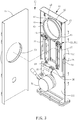
FIG. 1 is an elevational view of a dustproof gate valve in accordance with the present invention. -
FIG. 2 is a partial exploded view of the dustproof gate valve in accordance with the present invention, showing the state where the first panel is removed. -
FIG. 3 is another partial exploded view of the dustproof gate valve in accordance with the present invention, showing the state where the second panel is removed. -
FIG. 4 is an exploded view of the dustproof gate valve in accordance with the present invention. -
FIG. 5 correspond toFIG. 4 when viewed from another angle. -
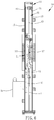
FIG. 6 is a sectional view taken along line 6-6 ofFIG. 1 . -
FIG. 7 is a schematic diagram of the operation of the dustproof gate valve in accordance with the present invention, showing the dust pipe moved to the valve port of the first panel and the valve port of the second panel. -
FIG. 8 is another schematic diagram of the operation of the dustproof gate valve in accordance with the present invention, showing the second panel removed. -
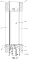
FIG. 9 is a sectional elevation of the dustproof gate valve in accordance with the present invention. -
FIG. 10 is a sectional view taken along line 10-10 ofFIG. 7 . - Referring to
FIGS. 1-10 , adustproof gate valve 10 in accordance with the present invention mainly comprises ahousing 11, aslide 21, adriver 31, aswing arm 35 and adust pipe 41. - The
housing 11 is flat, comprising afirst panel 13, asecond panel 15, and anaccommodation space 111 defined between thefirst panel 13 and thesecond panel 15. Thefirst panel 13 and thesecond panel 15 each have a valve port 131,151 cut therethrough and disposed opposite to each other. Thehousing 11 is internally provided with aguide rail set 12, which is substantially linear but has acurved portion 121 at one end. - The
slide 21 comprises abody 22 and avalve member 27. Thebody 22 is movably mounted in thehousing 11 and has adriving chute 23. Thevalve member 27 is movably mounted in thebody 22 and provided with apulley set 28. Thepulley set 28 is slidably mounted on the guide rail set 12 inside thehousing 11. Theslide 21 is driven to move between a first position P1 and a second position P2 by the assembly relationship of the pully set 28 and the guide rail set 12. When theslide 21 is at the first position P1, thepull set 28 enters thecurved portion 121 and drives thevalve member 27 to move to thefirst panel 13 in a straight line extending perpendicular to the guide rail set 12 and closes thevalve port 131 of thefirst panel 13. - The
driver 31 is mounted to thehousing 11. In this embodiment, thedriver 31 is a handle, and can be manually operated to rotate. However, in actual implementation, a pneumatic device such as a pneumatic cylinder or an electric device such as a motor can be used as the driver. - The
swing arm 35 has one end thereof connected to thedriver 31, and an opposite end thereof provided with asliding block 36 that is disposed in thedriving chute 23. Thedriver 31 is operated to drive the other end of theswing arm 35 for circular motion, and thesliding block 36 moves along thedriving chute 23 to act on the chute wall of thedriving chute 23, thereby driving theslide 21 to move. - The
dust pipe 41 is mounted on thebody 22. When theslide 21 is at the second position P2, thedust pipe 41 corresponds to thevalve port 131 of thefirst panel 13 and thevalve port 151 of thesecond panel 15 so that thevalve port 131 of thefirst panel 13 and thevalve port 151 of thesecond panel 15 are spatially connected to thedust pipe 41, and the pipe wall of thedust pipe 41 is located at the edges of thevalve ports first panel 13 and thesecond panel 15 to separate thevalve port 131 of thefirst panel 13 and thevalve port 151 of thesecond panel 15 from theaccommodation space 111. In addition, both ends of thedust pipe 41 are separated from thefirst panel 13 and thesecond panel 15 by a predetermined distance, leaving a gap S. In this embodiment, thedust pipe 41 is provided on thebody 22 through adust frame 45. Thedust pipe 41 has amounting groove 42 located on an outer wall thereof. Thedust frame 45 has aflange 46. Thedust pipe 41 is coupled to theflange 46 with itsmounting groove 42. In addition, thedust frame 45 has twoextension arms 47 extending in direction away from thebody 22. The twoextension arms 47 are located on two opposite sides of thedust pipe 41, each having a distal end provided with aroller 471. When theslide 21 is at the first position PI, therollers 471 of the twoextension arms 47 are stopped at the panel surface of thefirst panel 13. In actual implementation, thedust pipe 41 has a ring shape, as shown inFIGS. 2-5 , and both ends of thedust pipe 41 face thefirst panel 13 and thesecond panel 15, and the end edges of the two ends of thedust pipe 41 extend radially outward to form arespective shoulder 43. Thisshoulder 43 can increase the depth of the gap S between the two valve ports 131,151 and thedust pipe 41, making it more difficult for dust to enter thehousing 11 from the gap S. The arrangement of thisshoulder 43 can be decided according to the needs. Whether thedust pipe 41 is set without theshoulder 43 can also achieve the effect of dust prevention. Thedust pipe 41 can achieve the same dust-proof effect without theshoulder 43. Therefore, theshoulder 43 may not be provided. - The structure of the present invention has been described above, and the operation of the present invention is explained hereinafter.
- As shown in
FIGS. 2-6 , when closing thevalve port 131 of thefirst panel 13, thedriver 31 is operated to rotate theswing arm 35 to move theslide 21 to the first position P1. At this time, because the pulley set 28 of thevalve member 27 enters thecurved portion 121 to move thevalve member 27 in a straight line extending perpendicular to the guide rail set 12, thereby causing thevalve member 27 to move to thefirst panel 13 in the direction perpendicular to the guide rail set 12 and to close thevalve port 131 of thefirst panel 13. In this closed state, no air or dust can pass through thevalve port 131 of thefirst panel 13. As for whether thebody 22 moves in the direction perpendicular to the guide rail set 12 with thevalve member 27, it is a conventional technology, and will not be described in detail. If the present invention is used with thevalve member 27 facing downward, thedust pipe 41 may be forced by gravity to cause the twoextension arms 47 to sag. In case the twoextension arms 47 are forced to sag, therollers 471 at the ends of theextension arms 47 can be stopped against thefirst panel 13, thereby ensuring that thedust frame 45 does not touch thefirst panel 13. - As shown in
FIGS. 7-10 , when opening thevalve port 131 of thefirst panel 13, thedriver 31 is operated to rotate theswing arm 35 to move theslide 21 to the second position P2. At this time, thevalve member 27 is moved away from thevalve port 131 of thefirst panel 13 and thevalve port 151 of thesecond panel 15, and thedust pipe 41 is moved to the position between thevalve port 131 of thefirst panel 13 and thevalve port 151 of thesecond panel 15, enabling thevalve port 131 of thefirst panel 13 and thevalve port 151 of thesecond panel 15 to be spatially connected with thedust pipe 41. In this way, it is possible to form the same state as the conventional gate valve without the saiddust pipe 41 is opened. Since the pipe wall of thedust pipe 41 is located on the edges of thevalve ports first panel 13 and thesecond panel 15 to separate thevalve ports first panel 13 and thesecond panel 15 from theaccommodation space 111, the dust passing through thevalve port 131 of thefirst panel 13, thedust pipe 41 and thevalve port 151 of thesecond panel 15 is not easy to fall from the space between thefirst panel 13 and thesecond panel 15 into thehousing 11, thereby achieving the effect of dust prevention. - In addition, since the end edges of the two ends of the
dust pipe 41 are separated from thefirst panel 13 and thesecond panel 15 by a predetermined distance to leave the gap S, it can be ensured that when thedust pipe 41 is moving to the position between thevalve ports first panel 13 and thesecond panel 15, there will be no component collision or noise. Although the gap S may allow dust to enter thehousing 11, the amount of dust is very small compared to the conventional technology. In actual manufacturing, the gap S can be reduced by improving the assembly precision, thereby further reducing the amount of falling dust. - As can be seen from the above, the present invention can completely close the
valve port 131 of thefirst panel 13 when the dustproof gate valve is closed, and the gap S between the twovalve ports housing 11 can be shielded by thedust pipe 41 when the dustproof gate valve is opened. By blocking the dust and making it difficult to enter the dustproof gate valve, the present invention achieves the effect of dust prevention.
Claims (6)
- A dustproof gate valve (10), comprising:a housing (11) in a flat shape, said housing (11) comprising a first panel (13), a second panel (15), an accommodation space (111) defined between said first panel (13) and said second panel (15) and a guide rail set (12) disposed inside said housing (11), said first panel (13) and said second panel (15) each having a valve port (131)(151) disposed opposite to each other, said guide rail set (12) being substantially linear and having a curved portion (121) at one end thereof;a slide (21) comprising a body (22) and a valve member (27) located on said body (22), said body (22) being movably mounted in said housing (11) and providing a driving chute (23), said valve member (27) being movably mounted on said body (22), said valve member (27) comprising a pulley set (28), said pulley set (28) being slidably mounted on said guide rail set (12) inside said housing (11), said slide (21) being drivable to move between a first position (PI) and a second position (P2) by the assembly relationship between said pulley set (28) and said guide rail set (12), said pulley set (28) entering said curved portion (121) to move said valve member (27) to said first panel (13) in a linear extending direction perpendicular to said guide rail set (12) and to close said valve port (131) of said first panel (13) when said slide (21) is at said first position (PI);a driver (31) mounted in said housing (11); anda swing arm (35) having one end thereof connected to said driver (31) and an opposite end thereof provided with a sliding block (36) that is disposed in said driving chute (23), said driver (31) being operable to drive the other end of said swing arm (35) for circular motion, and said sliding block (36) being movable along said driving chute (23) to act on the chute wall of said driving chute (23), thereby driving said slide (21) to move;which is characterized in that said dustproof gate valve (10) further comprises:
a dust pipe (41) mounted in said body (22), said dust pipe (41) being disposed between said valve port (131) of said first panel (13) and said valve port (151) of said second panel (15) to spatially connect said valve port (131) of said first panel (13) and said valve port (151) of said second panel (15) to said dust pipe (41) when said slide (21) is at said second position (P2), and the pipe wall of said dust pipe (41) is located at the edges of said valve ports (131)(151) of said first panel (13) and said second panel (15) to separate said valve port (131) of said first panel (13) and said valve port (151) of said second panel (15) from said accommodation space (111). - The dustproof gate valve (10) as claimed in claim 1, wherein said dust pipe (41) is mounted on said body (22) by a dust frame (45).
- The dustproof gate valve (10) as claimed in claim 2, wherein said dust frame (45) comprises two extension arms (47) extending in direction away from said body (22) and respectively disposed at two opposite sides relative to said dust pipe (41), each said extension arm (47) having a roller (471) located at a distal end thereof, said rollers (471) of said two extension arms (47) being stopped against a panel surface of said first panel (13) when said slide (21) is at said first position (PI).
- The dustproof gate valve (10) as claimed in claim 2, wherein said dust pipe (41) comprises a mounting groove (42); said dust frame (45) comprises a flange (46) coupled to said mounting groove (42) of said dust pipe (41).
- The dustproof gate valve (10) as claimed in claim 1, wherein the two opposite ends of said dust pipe (41) are separated from said first panel (13) and said second panel (15) by a predetermined distance to leave a gap (S) when said slide (21) is at said second position (P2).
- The dustproof gate valve (10) as claimed in claim 1, wherein the end edges of the two opposite ends of said dust pipe (41) extend radially outward to form a respective shoulder (43).
Applications Claiming Priority (1)
| Application Number | Priority Date | Filing Date | Title |
|---|---|---|---|
| TW109100075A TWI716250B (en) | 2020-01-02 | 2020-01-02 | Gate valve with dustproof function |
Publications (3)
| Publication Number | Publication Date |
|---|---|
| EP3845788A1 true EP3845788A1 (en) | 2021-07-07 |
| EP3845788B1 EP3845788B1 (en) | 2023-10-04 |
| EP3845788C0 EP3845788C0 (en) | 2023-10-04 |
Family
ID=69187595
Family Applications (1)
| Application Number | Title | Priority Date | Filing Date |
|---|---|---|---|
| EP20153017.7A Active EP3845788B1 (en) | 2020-01-02 | 2020-01-22 | Dustproof gate valve |
Country Status (4)
| Country | Link |
|---|---|
| US (1) | US11112012B2 (en) |
| EP (1) | EP3845788B1 (en) |
| CN (2) | CN211924924U (en) |
| TW (1) | TWI716250B (en) |
Families Citing this family (3)
| Publication number | Priority date | Publication date | Assignee | Title |
|---|---|---|---|---|
| TWI716250B (en) * | 2020-01-02 | 2021-01-11 | 新萊應材科技有限公司 | Gate valve with dustproof function |
| CN117469414B (en) * | 2023-12-27 | 2024-04-30 | 四川九天真空科技有限公司 | A side-driven gate valve and drive system |
| US12510166B1 (en) * | 2024-10-04 | 2025-12-30 | Hui-Chuan Liao | Blast gate capable of preventing gate-dropping |
Citations (7)
| Publication number | Priority date | Publication date | Assignee | Title |
|---|---|---|---|---|
| US1844246A (en) * | 1929-12-11 | 1932-02-09 | Chapman Valve Mfg Co | Valve |
| US3610569A (en) * | 1969-10-02 | 1971-10-05 | Xomox Corp | Fluid control valve with retractable body seat |
| US4010928A (en) * | 1974-12-27 | 1977-03-08 | Xomox Corporation | Piston-operated parallel-slide gate valve |
| US4335733A (en) * | 1979-09-17 | 1982-06-22 | Richards John A | Valve for use in handling abrasive materials and method of wear prevention |
| EP2820337A1 (en) * | 2012-02-29 | 2015-01-07 | Fike Corporation | Pneumatic gate valve with integrated pressurized gas reservoir |
| US20160245412A1 (en) * | 2015-02-23 | 2016-08-25 | King Lai Hygienic Materials Co., Ltd | Gate valve with secure sealing mechanism |
| TWI551798B (en) | 2015-02-06 | 2016-10-01 | 新萊應材科技有限公司 | Gate valve with secure sealing mechanism |
Family Cites Families (14)
| Publication number | Priority date | Publication date | Assignee | Title |
|---|---|---|---|---|
| CA1266199A (en) * | 1985-01-28 | 1990-02-27 | Waldemar H. Greiner | Damper construction |
| US4718637A (en) * | 1986-07-02 | 1988-01-12 | Mdc Vacuum Products Corporation | High vacuum gate valve having improved metal vacuum joint |
| JP2001165334A (en) * | 1999-12-06 | 2001-06-22 | Smc Corp | Gate valve having swing gate |
| JP3588637B2 (en) * | 2001-03-28 | 2004-11-17 | 株式会社ブイテックス | Flow control valve |
| US7611124B2 (en) * | 2004-12-22 | 2009-11-03 | Tokyo Electron Limited | Vacuum processing apparatus |
| DE102005043595A1 (en) * | 2005-09-12 | 2007-04-19 | Bösch, Hubert | Valve mechanism for a vacuum valve |
| WO2014174926A1 (en) * | 2013-04-22 | 2014-10-30 | Ckd株式会社 | Gate valve |
| EP2949975B1 (en) * | 2014-05-22 | 2017-03-29 | Rico-Sicherheitstechnik AG | Explosion protection gate valve for interrupting a fluid flow in a pipeline |
| JP6160926B2 (en) * | 2014-06-05 | 2017-07-12 | Smc株式会社 | Gate valve |
| TWI580881B (en) * | 2015-02-06 | 2017-05-01 | 新萊應材科技有限公司 | Gate valve with secure sealing mechanism |
| CN207018556U (en) * | 2017-07-04 | 2018-02-16 | 成都乘风阀门有限责任公司 | Can on-line maintenance upper dress flat gate valve |
| CN207796110U (en) * | 2018-01-04 | 2018-08-31 | 湖北津源阀门制造股份有限公司 | A kind of smoke valve lock |
| TWI716250B (en) * | 2020-01-02 | 2021-01-11 | 新萊應材科技有限公司 | Gate valve with dustproof function |
| TWM595181U (en) * | 2020-01-02 | 2020-05-11 | 新萊應材科技有限公司 | Gate valve with dustproof function |
-
2020
- 2020-01-02 TW TW109100075A patent/TWI716250B/en active
- 2020-01-19 CN CN202020121764.7U patent/CN211924924U/en not_active Withdrawn - After Issue
- 2020-01-19 CN CN202010069958.1A patent/CN113062991B/en active Active
- 2020-01-22 EP EP20153017.7A patent/EP3845788B1/en active Active
- 2020-01-30 US US16/776,568 patent/US11112012B2/en active Active
Patent Citations (8)
| Publication number | Priority date | Publication date | Assignee | Title |
|---|---|---|---|---|
| US1844246A (en) * | 1929-12-11 | 1932-02-09 | Chapman Valve Mfg Co | Valve |
| US3610569A (en) * | 1969-10-02 | 1971-10-05 | Xomox Corp | Fluid control valve with retractable body seat |
| US4010928A (en) * | 1974-12-27 | 1977-03-08 | Xomox Corporation | Piston-operated parallel-slide gate valve |
| US4335733A (en) * | 1979-09-17 | 1982-06-22 | Richards John A | Valve for use in handling abrasive materials and method of wear prevention |
| EP2820337A1 (en) * | 2012-02-29 | 2015-01-07 | Fike Corporation | Pneumatic gate valve with integrated pressurized gas reservoir |
| TWI551798B (en) | 2015-02-06 | 2016-10-01 | 新萊應材科技有限公司 | Gate valve with secure sealing mechanism |
| US20160245412A1 (en) * | 2015-02-23 | 2016-08-25 | King Lai Hygienic Materials Co., Ltd | Gate valve with secure sealing mechanism |
| US9464721B2 (en) | 2015-02-23 | 2016-10-11 | King Lai Hygienic Material Co., Ltd | Gate valve with secure sealing mechanism |
Also Published As
| Publication number | Publication date |
|---|---|
| CN211924924U (en) | 2020-11-13 |
| US11112012B2 (en) | 2021-09-07 |
| CN113062991B (en) | 2022-12-06 |
| EP3845788B1 (en) | 2023-10-04 |
| EP3845788C0 (en) | 2023-10-04 |
| US20210207719A1 (en) | 2021-07-08 |
| TWI716250B (en) | 2021-01-11 |
| CN113062991A (en) | 2021-07-02 |
| TW202126935A (en) | 2021-07-16 |
Similar Documents
| Publication | Publication Date | Title |
|---|---|---|
| US11112012B2 (en) | Dustproof gate valve | |
| WO2017101781A1 (en) | Panel component and air conditioner | |
| CN109690007B (en) | Power sliding window | |
| US6116830A (en) | Telescopic protective shield for following the movements of a moving part | |
| MX2022015474A (en) | A door operator system. | |
| JPH09303518A (en) | No-suction clean actuator | |
| CN107756133A (en) | Safety doors and CNC machine tools | |
| MX2022008446A (en) | DOOR OPERATOR SYSTEM. | |
| CN110821332B (en) | Explosion-proof type automatic spinning door device | |
| MX2021015086A (en) | Door operator system. | |
| EP0565786A1 (en) | Vacuum gate valve | |
| TWM595181U (en) | Gate valve with dustproof function | |
| CN205316637U (en) | Panel components and air conditioners | |
| JP2663584B2 (en) | Linear transport device for working mechanism | |
| CN1292974C (en) | Drive device for circular elevator door | |
| CN222686537U (en) | Vacuum sealing device | |
| CN111823278B (en) | A protection mechanism and a manipulator | |
| CN215967428U (en) | Feeding skylight device and processing equipment thereof | |
| KR102043867B1 (en) | Door system for auxiliary power unit of vehicle | |
| CA2527465A1 (en) | Bill processing apparatus | |
| JP2001277069A (en) | Machine tool door device | |
| CN211681197U (en) | Novel machine tool metal plate protective door | |
| CN211551821U (en) | Air conditioner | |
| CN211889433U (en) | Linear module, workbench and automation equipment | |
| CN214559461U (en) | A machine tool cover with adjustable opening |
Legal Events
| Date | Code | Title | Description |
|---|---|---|---|
| STAA | Information on the status of an ep patent application or granted ep patent |
Free format text: STATUS: REQUEST FOR EXAMINATION WAS MADE |
|
| PUAI | Public reference made under article 153(3) epc to a published international application that has entered the european phase |
Free format text: ORIGINAL CODE: 0009012 |
|
| 17P | Request for examination filed |
Effective date: 20200122 |
|
| AK | Designated contracting states |
Kind code of ref document: A1 Designated state(s): AL AT BE BG CH CY CZ DE DK EE ES FI FR GB GR HR HU IE IS IT LI LT LU LV MC MK MT NL NO PL PT RO RS SE SI SK SM TR |
|
| GRAP | Despatch of communication of intention to grant a patent |
Free format text: ORIGINAL CODE: EPIDOSNIGR1 |
|
| STAA | Information on the status of an ep patent application or granted ep patent |
Free format text: STATUS: GRANT OF PATENT IS INTENDED |
|
| INTG | Intention to grant announced |
Effective date: 20230522 |
|
| RIN1 | Information on inventor provided before grant (corrected) |
Inventor name: HUANG, CHI-CHE Inventor name: LEE, CHUN-CHUN |
|
| GRAS | Grant fee paid |
Free format text: ORIGINAL CODE: EPIDOSNIGR3 |
|
| GRAA | (expected) grant |
Free format text: ORIGINAL CODE: 0009210 |
|
| STAA | Information on the status of an ep patent application or granted ep patent |
Free format text: STATUS: THE PATENT HAS BEEN GRANTED |
|
| AK | Designated contracting states |
Kind code of ref document: B1 Designated state(s): AL AT BE BG CH CY CZ DE DK EE ES FI FR GB GR HR HU IE IS IT LI LT LU LV MC MK MT NL NO PL PT RO RS SE SI SK SM TR |
|
| REG | Reference to a national code |
Ref country code: GB Ref legal event code: FG4D |
|
| REG | Reference to a national code |
Ref country code: CH Ref legal event code: EP |
|
| REG | Reference to a national code |
Ref country code: IE Ref legal event code: FG4D |
|
| REG | Reference to a national code |
Ref country code: DE Ref legal event code: R096 Ref document number: 602020018456 Country of ref document: DE |
|
| U01 | Request for unitary effect filed |
Effective date: 20231004 |
|
| U07 | Unitary effect registered |
Designated state(s): AT BE BG DE DK EE FI FR IT LT LU LV MT NL PT SE SI Effective date: 20231012 |
|
| U20 | Renewal fee for the european patent with unitary effect paid |
Year of fee payment: 5 Effective date: 20231228 |
|
| PG25 | Lapsed in a contracting state [announced via postgrant information from national office to epo] |
Ref country code: GR Free format text: LAPSE BECAUSE OF FAILURE TO SUBMIT A TRANSLATION OF THE DESCRIPTION OR TO PAY THE FEE WITHIN THE PRESCRIBED TIME-LIMIT Effective date: 20240105 |
|
| PG25 | Lapsed in a contracting state [announced via postgrant information from national office to epo] |
Ref country code: IS Free format text: LAPSE BECAUSE OF FAILURE TO SUBMIT A TRANSLATION OF THE DESCRIPTION OR TO PAY THE FEE WITHIN THE PRESCRIBED TIME-LIMIT Effective date: 20240204 |
|
| PG25 | Lapsed in a contracting state [announced via postgrant information from national office to epo] |
Ref country code: ES Free format text: LAPSE BECAUSE OF FAILURE TO SUBMIT A TRANSLATION OF THE DESCRIPTION OR TO PAY THE FEE WITHIN THE PRESCRIBED TIME-LIMIT Effective date: 20231004 |
|
| PG25 | Lapsed in a contracting state [announced via postgrant information from national office to epo] |
Ref country code: IS Free format text: LAPSE BECAUSE OF FAILURE TO SUBMIT A TRANSLATION OF THE DESCRIPTION OR TO PAY THE FEE WITHIN THE PRESCRIBED TIME-LIMIT Effective date: 20240204 Ref country code: GR Free format text: LAPSE BECAUSE OF FAILURE TO SUBMIT A TRANSLATION OF THE DESCRIPTION OR TO PAY THE FEE WITHIN THE PRESCRIBED TIME-LIMIT Effective date: 20240105 Ref country code: ES Free format text: LAPSE BECAUSE OF FAILURE TO SUBMIT A TRANSLATION OF THE DESCRIPTION OR TO PAY THE FEE WITHIN THE PRESCRIBED TIME-LIMIT Effective date: 20231004 |
|
| PG25 | Lapsed in a contracting state [announced via postgrant information from national office to epo] |
Ref country code: RS Free format text: LAPSE BECAUSE OF FAILURE TO SUBMIT A TRANSLATION OF THE DESCRIPTION OR TO PAY THE FEE WITHIN THE PRESCRIBED TIME-LIMIT Effective date: 20231004 Ref country code: PL Free format text: LAPSE BECAUSE OF FAILURE TO SUBMIT A TRANSLATION OF THE DESCRIPTION OR TO PAY THE FEE WITHIN THE PRESCRIBED TIME-LIMIT Effective date: 20231004 Ref country code: NO Free format text: LAPSE BECAUSE OF FAILURE TO SUBMIT A TRANSLATION OF THE DESCRIPTION OR TO PAY THE FEE WITHIN THE PRESCRIBED TIME-LIMIT Effective date: 20240104 Ref country code: HR Free format text: LAPSE BECAUSE OF FAILURE TO SUBMIT A TRANSLATION OF THE DESCRIPTION OR TO PAY THE FEE WITHIN THE PRESCRIBED TIME-LIMIT Effective date: 20231004 |
|
| REG | Reference to a national code |
Ref country code: DE Ref legal event code: R097 Ref document number: 602020018456 Country of ref document: DE |
|
| PG25 | Lapsed in a contracting state [announced via postgrant information from national office to epo] |
Ref country code: CZ Free format text: LAPSE BECAUSE OF FAILURE TO SUBMIT A TRANSLATION OF THE DESCRIPTION OR TO PAY THE FEE WITHIN THE PRESCRIBED TIME-LIMIT Effective date: 20231004 |
|
| PG25 | Lapsed in a contracting state [announced via postgrant information from national office to epo] |
Ref country code: SK Free format text: LAPSE BECAUSE OF FAILURE TO SUBMIT A TRANSLATION OF THE DESCRIPTION OR TO PAY THE FEE WITHIN THE PRESCRIBED TIME-LIMIT Effective date: 20231004 |
|
| PG25 | Lapsed in a contracting state [announced via postgrant information from national office to epo] |
Ref country code: SM Free format text: LAPSE BECAUSE OF FAILURE TO SUBMIT A TRANSLATION OF THE DESCRIPTION OR TO PAY THE FEE WITHIN THE PRESCRIBED TIME-LIMIT Effective date: 20231004 Ref country code: SK Free format text: LAPSE BECAUSE OF FAILURE TO SUBMIT A TRANSLATION OF THE DESCRIPTION OR TO PAY THE FEE WITHIN THE PRESCRIBED TIME-LIMIT Effective date: 20231004 Ref country code: RO Free format text: LAPSE BECAUSE OF FAILURE TO SUBMIT A TRANSLATION OF THE DESCRIPTION OR TO PAY THE FEE WITHIN THE PRESCRIBED TIME-LIMIT Effective date: 20231004 Ref country code: CZ Free format text: LAPSE BECAUSE OF FAILURE TO SUBMIT A TRANSLATION OF THE DESCRIPTION OR TO PAY THE FEE WITHIN THE PRESCRIBED TIME-LIMIT Effective date: 20231004 |
|
| PLBE | No opposition filed within time limit |
Free format text: ORIGINAL CODE: 0009261 |
|
| STAA | Information on the status of an ep patent application or granted ep patent |
Free format text: STATUS: NO OPPOSITION FILED WITHIN TIME LIMIT |
|
| PG25 | Lapsed in a contracting state [announced via postgrant information from national office to epo] |
Ref country code: MC Free format text: LAPSE BECAUSE OF FAILURE TO SUBMIT A TRANSLATION OF THE DESCRIPTION OR TO PAY THE FEE WITHIN THE PRESCRIBED TIME-LIMIT Effective date: 20231004 |
|
| PG25 | Lapsed in a contracting state [announced via postgrant information from national office to epo] |
Ref country code: MC Free format text: LAPSE BECAUSE OF FAILURE TO SUBMIT A TRANSLATION OF THE DESCRIPTION OR TO PAY THE FEE WITHIN THE PRESCRIBED TIME-LIMIT Effective date: 20231004 |
|
| REG | Reference to a national code |
Ref country code: CH Ref legal event code: PL |
|
| 26N | No opposition filed |
Effective date: 20240705 |
|
| PG25 | Lapsed in a contracting state [announced via postgrant information from national office to epo] |
Ref country code: CH Free format text: LAPSE BECAUSE OF NON-PAYMENT OF DUE FEES Effective date: 20240131 |
|
| PG25 | Lapsed in a contracting state [announced via postgrant information from national office to epo] |
Ref country code: CH Free format text: LAPSE BECAUSE OF NON-PAYMENT OF DUE FEES Effective date: 20240131 |
|
| PG25 | Lapsed in a contracting state [announced via postgrant information from national office to epo] |
Ref country code: IE Free format text: LAPSE BECAUSE OF NON-PAYMENT OF DUE FEES Effective date: 20240122 |
|
| PG25 | Lapsed in a contracting state [announced via postgrant information from national office to epo] |
Ref country code: IE Free format text: LAPSE BECAUSE OF NON-PAYMENT OF DUE FEES Effective date: 20240122 |
|
| U20 | Renewal fee for the european patent with unitary effect paid |
Year of fee payment: 6 Effective date: 20241231 |
|
| PGFP | Annual fee paid to national office [announced via postgrant information from national office to epo] |
Ref country code: GB Payment date: 20250123 Year of fee payment: 6 |
|
| PG25 | Lapsed in a contracting state [announced via postgrant information from national office to epo] |
Ref country code: CY Free format text: LAPSE BECAUSE OF FAILURE TO SUBMIT A TRANSLATION OF THE DESCRIPTION OR TO PAY THE FEE WITHIN THE PRESCRIBED TIME-LIMIT; INVALID AB INITIO Effective date: 20200122 |
|
| PG25 | Lapsed in a contracting state [announced via postgrant information from national office to epo] |
Ref country code: HU Free format text: LAPSE BECAUSE OF FAILURE TO SUBMIT A TRANSLATION OF THE DESCRIPTION OR TO PAY THE FEE WITHIN THE PRESCRIBED TIME-LIMIT; INVALID AB INITIO Effective date: 20200122 |
|
| PG25 | Lapsed in a contracting state [announced via postgrant information from national office to epo] |
Ref country code: TR Free format text: LAPSE BECAUSE OF FAILURE TO SUBMIT A TRANSLATION OF THE DESCRIPTION OR TO PAY THE FEE WITHIN THE PRESCRIBED TIME-LIMIT Effective date: 20231004 |