EP3845809A1 - Dispositif et procédé d'inspection d'une chambre de combustion - Google Patents
Dispositif et procédé d'inspection d'une chambre de combustion Download PDFInfo
- Publication number
- EP3845809A1 EP3845809A1 EP19425102.1A EP19425102A EP3845809A1 EP 3845809 A1 EP3845809 A1 EP 3845809A1 EP 19425102 A EP19425102 A EP 19425102A EP 3845809 A1 EP3845809 A1 EP 3845809A1
- Authority
- EP
- European Patent Office
- Prior art keywords
- coupled
- rotational joint
- sensing probe
- combustor
- joint
- Prior art date
- Legal status (The legal status is an assumption and is not a legal conclusion. Google has not performed a legal analysis and makes no representation as to the accuracy of the status listed.)
- Granted
Links
Images



Classifications
-
- F—MECHANICAL ENGINEERING; LIGHTING; HEATING; WEAPONS; BLASTING
- F23—COMBUSTION APPARATUS; COMBUSTION PROCESSES
- F23R—GENERATING COMBUSTION PRODUCTS OF HIGH PRESSURE OR HIGH VELOCITY, e.g. GAS-TURBINE COMBUSTION CHAMBERS
- F23R3/00—Continuous combustion chambers using liquid or gaseous fuel
-
- G—PHYSICS
- G01—MEASURING; TESTING
- G01N—INVESTIGATING OR ANALYSING MATERIALS BY DETERMINING THEIR CHEMICAL OR PHYSICAL PROPERTIES
- G01N21/00—Investigating or analysing materials by the use of optical means, i.e. using sub-millimetre waves, infrared, visible or ultraviolet light
- G01N21/84—Systems specially adapted for particular applications
- G01N21/88—Investigating the presence of flaws or contamination
-
- B—PERFORMING OPERATIONS; TRANSPORTING
- B25—HAND TOOLS; PORTABLE POWER-DRIVEN TOOLS; MANIPULATORS
- B25J—MANIPULATORS; CHAMBERS PROVIDED WITH MANIPULATION DEVICES
- B25J9/00—Program-controlled manipulators
- B25J9/06—Program-controlled manipulators characterised by multi-articulated arms
-
- B—PERFORMING OPERATIONS; TRANSPORTING
- B25—HAND TOOLS; PORTABLE POWER-DRIVEN TOOLS; MANIPULATORS
- B25J—MANIPULATORS; CHAMBERS PROVIDED WITH MANIPULATION DEVICES
- B25J9/00—Program-controlled manipulators
- B25J9/10—Program-controlled manipulators characterised by positioning means for manipulator elements
- B25J9/104—Program-controlled manipulators characterised by positioning means for manipulator elements with cables, chains or ribbons
-
- F—MECHANICAL ENGINEERING; LIGHTING; HEATING; WEAPONS; BLASTING
- F23—COMBUSTION APPARATUS; COMBUSTION PROCESSES
- F23R—GENERATING COMBUSTION PRODUCTS OF HIGH PRESSURE OR HIGH VELOCITY, e.g. GAS-TURBINE COMBUSTION CHAMBERS
- F23R2900/00—Special features of, or arrangements for continuous combustion chambers; Combustion processes therefor
- F23R2900/00019—Repairing or maintaining combustion chamber liners or subparts
Definitions
- the present invention relates to a device and method for inspecting a combustor.
- the device and the method of the present invention are useful for inspecting the combustor of an industrial gas turbine assembly for power generation.
- an industrial gas turbine assembly for power generation comprises a compressor, a combustor and a turbine.
- the compressor comprises an inlet supplied with air and a plurality of rotating blades compressing the passing air.
- the compressed air leaving the compressor flows into a plenum, i.e. a closed volume delimited by an outer casing, and from there into the combustor.
- a plenum i.e. a closed volume delimited by an outer casing
- the compressed air is mixed with at least one fuel and combusted.
- the resulting hot gas leaves the combustor and expands in the turbine. In the turbine the hot gas expansion moves rotating blades connected to a rotor, performing work.
- the inner walls of the combustor require effective thermal protection as during combustion they are exposed to high-temperatures.
- Tiles made of ceramic material are usually applied on the walls of the combustor for protection. Ceramic materials are suitable for this application because they provide good thermal protection and have low conductivity.
- the combustor is normally inspected by a human operator, highly trained, which is normally called in the field as the "fact finder".
- a not-scheduled stop is the automatic shutdown event activated by the gas turbine protection system after the detection of high accelerations of the gas turbine.
- the inspection of the interior of the combustor is mandatory as in this case, the probability that the ceramic tiles may have been damaged by high accelerations is not negligible.
- the object of the present invention is therefore to develop an automatic inspection device and method, aimed at supporting the operator in the checking phase of the combustor
- the present invention relates to a device for inspecting a combustor comprising:
- reference numeral 1 indicates a gas turbine assembly for electrical energy production comprising a compressor 3, a combustor 4, a gas turbine 5 and a generator 7, which transforms the mechanical power supplied by turbine 5 into electrical power to be supplied to an electrical grid 8, connected to the generator 7 via a switch 9.
- assembly 1 to be of the combined cycle type and including, in addition to the gas turbine 5 and generator 7, also a steam turbine.
- the gas turbine 5 extends along a longitudinal axis A and is provided with a shaft 10 (also extending along axis A) to which compressor 3 and generator 7 are also connected.
- Gas turbine 5 comprises an expansion channel 12 wherein the hot gas working fluid coming from the combustor 4 flows in a direction D.
- the expansion channel 12 has a section, which radially increases along the axis A in the direction D.
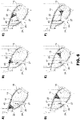
- the combustor 4 is provided with a casing 13, which defines a combustion area 15 (see figures 5a-5h and 6a-6f ).
- the combustion chamber 4 is of annular type and has a substantially toroidal shape.
- Casing 13 has a substantially annular shape and is provided with an inner lining 17 (see figures 6a-6f ), defined by a plurality of tiles made of refractory material, which are arranged in adjacent columns.
- number 20 indicates a device for inspecting the combustor 4 according to the present invention.
- Device 20 comprises a sensing probe 22 and an arm 23 having one first end 24 coupled to the sensing probe 22 and one second end 25 coupled to a base 26.
- the arm 23 comprising a plurality of modules 27 coupled to one another.
- the modules 27 have a light structure.
- the modules 27 have a reticular structure.
- each module 27 is coupled to the adjacent module 27 with a respective rotational joint 28.
- Each rotational joint 28 is independently controlled. In other words, each rotational joint 28 can move independently from the others.
- Each rotational joint 28 is configured to allow the rotation about a respective axis of rotation B1, B2, B3, ... B9.
- the axes of rotation B1, B2, B3, ... B9 of the rotational joints 28 are parallel.
- each rotational joint 28 comprises a main pulley 30 and two cables 31, which are fixed to the main pulley 30 and move in opposite directions.
- Each cable 31 is coupled to a respective motor 33 (schematically represented with a box in figures 2 and 3 ).
- Each motor 33 is configured to move the respective cable 31 in a controlled way.
- Each motor 33 in fact, is controlled by a control device (not shown).
- the base 26 is coupled to a carriage (not shown) useful for moving the device 20.
- each module 27 comprises at least one cable guide 35 configured to house at least a portion of at least one cable 31 of the rotational joint 28 associated to said module 27.
- the cable guide 35 is a bar provided with at least one aperture 34 through which the cables pass.
- each cable 31 can cooperate with at least one free pulley (not shown) for guiding the cable 31 along the desired path and for avoiding intersections between the cables of the others rotational joints.
- each rotational joint 28 comprises at least one position transducer 36 (better visible in figure 4 ), able to detect the current relative position between the modules 27 connected by the main pulley 30.
- the position transducer 36 is an encoder fixed to one of the modules 27 coupled by the rotational joint 28 and able to detect the position of the other module of the modules 27 coupled by the rotational joint 28 or, alternatively, the position of the respective main pulley 30.
- the main pulley 30 comprises a disc 40, which is centrally crossed by a pin 41 which is fixed to one of the modules 27 coupled by the rotational joint 28.
- the pin 41 and the pulley 30 are free to move one with respect to the other.
- a bearing (not visible) is arranged between the pulley 30 and the pin 41.
- the position transducer 36 is preferably coupled to the module 27 fixed to pin 41 in the proximity of one end of the pin 41.
- the disc 40 is fixed to the other of the modules 27 coupled by the rotational joint 28, preferably by means of at least one bar 43.
- each rotational joint 28 couples two modules 27.
- One of the two modules 27 is fixed to the main pulley 30, while the other of the two modules 27 is fixed to the pin 41 passing through the main pulley 41.
- the sensing probe 22 is coupled to the first end 24 with a further joint 45.
- Joint 45 can be coupled to one or more actuating devices (not shown) configured to move the joint 45 in a controlled way.
- the one or more actuating devices associated to the joint 45 can be housed in the base 26 or can be arranged in the proximity of the joint 45. In case the actuating devices are arranged near the joint 45, a dedicated cooling device can be provided for properly cooling them.
- the joint 45 is a rotational joint configured to allow the rotation about a further axis of rotation C, which is orthogonal to the axes of rotation B1, B2,...B9 of the rotational joints 28 connecting the modules 27. In this way the sensing probe 22 can be moved closer to the tiles of the inner lining 17 in order to get a proper signal.
- the joint 45 has at least three degrees of freedom that allow the sensor probe 22 to be oriented in various spatial directions.
- the joint 45 comprises a first rotational joint 48, a second rotational joint 49 and a third rotational joint 50.
- the first rotational joint 48, the second rotational joint 49 and the third rotational joint 50 are joints with a range of movement +/- 180°.
- the first rotational joint 48 is coupled to the end 24 of the arm 23. In other words, the first rotational joint 48 is coupled to the terminal module 27.
- the joint 45 is a spherical joint.
- the joint 45 has three degrees of freedom as it comprises a first rotational joint 52, a second rotational joint 53 and a telescopic mechanism 54.
- the telescopic mechanism 54 allows the sensor probe 22 to get closer to the tiles of the inner lining 17.
- the first rotational joint 52 and the second rotational joint 53 are joints with a range of movement +/-180° .
- the sensing probe 22 is a multi-sensing probe.
- the sensing probe 22 comprises a thermal and optical imaging camera configured to acquires IR and RGB images in order to detect and classify damages inside the combustor 4.
- the data collected by the sensing probe 22 are collected and elaborated by a data processor in order to map the entire inner lining 17.
- the sensing probe 22 comprises also a cooling device and a temperature sensor (not shown) able to detect a temperature value useful for the cooling device.
- the sensing probe 22 and the moving of the joint 45 is regulated by the control device (not shown).In use, the inspection of the combustor 4 is made when the plant is stopped.
- the sensor probe 22 is introduced into the combustion area 15 through an opening 50 of the casing 14 and is moved along at least a portion of a circumferential path thanks to the regulation of the position of each rotational joint 28 of the arm 23.
- the sensing probe 22 is moved along the circumferential path avoiding any contacts between the sensing probe 22 and inner lining 17 of the combustor 4.
- each rotational joint 28 is regulated by opportunely actuating the motors 22 associated to the rotational joint 28.
- the base 26 is always maintained outside the combustion area 15.
- the device 20 is in a parking position, with the arm 23 rolled up on itself. In the parking position, the device 20 can be easily transported.
- motors of the joint 45 are supported by the arm 23.
- the motors are provided with a cooling arrangement.
- the sensing probe 22 can have another degree of freedom thanks to the rotational joint 45. In this way, a complete mapping of the inner lining 17 of the combustion chamber can be simply obtained.
- the sensing probe 22 can move with three degrees of freedom. In this way the sensing probe 22 can move properly inside the combustion area in order to get current images of the inner lining 17.
- the distance between the inner lining 17 and the sensing probe 22 can be properly regulated in order to acquire optimal images.
- IR images can be acquired without the aid of artificial lighting, while RGB images are acquired preferably when an artificial light (not shown) is activated in order to get optimal visible images of the inner lining 17.
- IR images and RGB images can be acquired contemporaneously or in different steps.
- Control device is configured to identify in IR images the areas wherein the gradient of temperature is associated to a defect indication. These areas are candidates to be defects/cracks, as near defect/cracks the temperature is normally different from the temperature of the other undamaged areas of the inner lining 17.
- RGB images are then useful to evaluate, by a different method, the potential defects found with IR images and to evaluate other type of defects (not limited to cracks) in the combustor 4.
- the robotic arm 23 can move in higher temperature environment (50°-200°C) with respect to a human operator (max 40°C).
- the inspection can start also when the internal temperature is around 100°C.
- the inspection can be performed in advance with respect to the current solution with a human operator.
- Another important advantage is that the human operator requires the opening of a wide "man-hole” to access the combustion area 15.
- the area of this "man-hole” corresponds to a surface of six tiles.
- the device of the present invention Using the device of the present invention a smaller and faster aperture 50 is required to enter the combustion area 15. Normally, the area of the aperture 50 required for the access of the device according to the invention corresponds to a surface of one or maximum two tiles.
- the unscheduled stoppage time is shortened, thus limiting the production loss and, consequently, the economic loss.
- the above described method and device for inspecting the combustor advantageously introduce an automation of the process of analysis and detection of defects in the tiles.
Landscapes
- Engineering & Computer Science (AREA)
- Mechanical Engineering (AREA)
- Robotics (AREA)
- Chemical & Material Sciences (AREA)
- Analytical Chemistry (AREA)
- Biochemistry (AREA)
- General Health & Medical Sciences (AREA)
- General Physics & Mathematics (AREA)
- Immunology (AREA)
- Pathology (AREA)
- Physics & Mathematics (AREA)
- Combustion & Propulsion (AREA)
- Life Sciences & Earth Sciences (AREA)
- General Engineering & Computer Science (AREA)
- Health & Medical Sciences (AREA)
- Investigating Or Analyzing Materials Using Thermal Means (AREA)
- Testing Of Devices, Machine Parts, Or Other Structures Thereof (AREA)
Priority Applications (2)
| Application Number | Priority Date | Filing Date | Title |
|---|---|---|---|
| EP19425102.1A EP3845809B1 (fr) | 2019-12-31 | 2019-12-31 | Dispositif et procédé d'inspection d'une chambre de combustion |
| CN202011627688.8A CN113125441A (zh) | 2019-12-31 | 2020-12-31 | 用于检查燃烧器的装置和方法 |
Applications Claiming Priority (1)
| Application Number | Priority Date | Filing Date | Title |
|---|---|---|---|
| EP19425102.1A EP3845809B1 (fr) | 2019-12-31 | 2019-12-31 | Dispositif et procédé d'inspection d'une chambre de combustion |
Publications (2)
| Publication Number | Publication Date |
|---|---|
| EP3845809A1 true EP3845809A1 (fr) | 2021-07-07 |
| EP3845809B1 EP3845809B1 (fr) | 2023-11-29 |
Family
ID=69631404
Family Applications (1)
| Application Number | Title | Priority Date | Filing Date |
|---|---|---|---|
| EP19425102.1A Active EP3845809B1 (fr) | 2019-12-31 | 2019-12-31 | Dispositif et procédé d'inspection d'une chambre de combustion |
Country Status (2)
| Country | Link |
|---|---|
| EP (1) | EP3845809B1 (fr) |
| CN (1) | CN113125441A (fr) |
Families Citing this family (1)
| Publication number | Priority date | Publication date | Assignee | Title |
|---|---|---|---|---|
| CN113829386A (zh) * | 2021-08-26 | 2021-12-24 | 北京精密机电控制设备研究所 | 一种具有可伸缩自由度的连续型充电机械臂 |
Citations (7)
| Publication number | Priority date | Publication date | Assignee | Title |
|---|---|---|---|---|
| DE19924607A1 (de) * | 1999-05-28 | 2000-11-30 | Siemens Ag | Inspektionsvorrichtung für eine Ringbrennkammer einer Gasturbine und Verfahren zur Inspektion einer Ringbrennkammer einer Gasturbine |
| DE202004012584U1 (de) * | 2004-08-10 | 2005-01-05 | Zf Friedrichshafen Ag | Roboter |
| WO2008002454A2 (fr) * | 2006-06-28 | 2008-01-03 | Genmark Automation, Inc. | Robot doté d'un système de transmission par courroies |
| US20120312103A1 (en) * | 2009-11-10 | 2012-12-13 | Kerstin Hannott | Inspection device and method for positioning an inspection device |
| WO2013116078A1 (fr) * | 2012-01-31 | 2013-08-08 | Siemens Energy, Inc. | Système et procédé d'inspection optique automatisée de turbines à gaz industrielles et d'autres machines de production d'énergie ayant un périmètre d'inspection multi-axe |
| US20160212360A1 (en) * | 2015-01-21 | 2016-07-21 | Siemens Energy, Inc. | In-situ inspection of power generating machinery |
| US20170362939A1 (en) * | 2016-06-17 | 2017-12-21 | General Electric Company | System and method for performing an in situ repair of an internal component of a gas turbine engine |
Family Cites Families (4)
| Publication number | Priority date | Publication date | Assignee | Title |
|---|---|---|---|---|
| US8786848B2 (en) * | 2011-05-05 | 2014-07-22 | Siemens Energy, Inc. | Inspection system for a combustor of a turbine engine |
| US9709463B2 (en) * | 2012-01-31 | 2017-07-18 | Siemens Energy, Inc. | Method and system for surface profile inspection of off-line industrial gas turbines and other power generation machinery |
| JP2015526642A (ja) * | 2012-08-23 | 2015-09-10 | シーメンス エナジー インコーポレイテッド | 回転ギアモード中のオフライン産業用ガスタービンおよび他の発電機械の光学検査システムおよび方法 |
| US9228941B2 (en) * | 2012-11-07 | 2016-01-05 | Solar Turbines Incorporated | Combustor imaging inspection system |
-
2019
- 2019-12-31 EP EP19425102.1A patent/EP3845809B1/fr active Active
-
2020
- 2020-12-31 CN CN202011627688.8A patent/CN113125441A/zh active Pending
Patent Citations (7)
| Publication number | Priority date | Publication date | Assignee | Title |
|---|---|---|---|---|
| DE19924607A1 (de) * | 1999-05-28 | 2000-11-30 | Siemens Ag | Inspektionsvorrichtung für eine Ringbrennkammer einer Gasturbine und Verfahren zur Inspektion einer Ringbrennkammer einer Gasturbine |
| DE202004012584U1 (de) * | 2004-08-10 | 2005-01-05 | Zf Friedrichshafen Ag | Roboter |
| WO2008002454A2 (fr) * | 2006-06-28 | 2008-01-03 | Genmark Automation, Inc. | Robot doté d'un système de transmission par courroies |
| US20120312103A1 (en) * | 2009-11-10 | 2012-12-13 | Kerstin Hannott | Inspection device and method for positioning an inspection device |
| WO2013116078A1 (fr) * | 2012-01-31 | 2013-08-08 | Siemens Energy, Inc. | Système et procédé d'inspection optique automatisée de turbines à gaz industrielles et d'autres machines de production d'énergie ayant un périmètre d'inspection multi-axe |
| US20160212360A1 (en) * | 2015-01-21 | 2016-07-21 | Siemens Energy, Inc. | In-situ inspection of power generating machinery |
| US20170362939A1 (en) * | 2016-06-17 | 2017-12-21 | General Electric Company | System and method for performing an in situ repair of an internal component of a gas turbine engine |
Also Published As
| Publication number | Publication date |
|---|---|
| EP3845809B1 (fr) | 2023-11-29 |
| CN113125441A (zh) | 2021-07-16 |
Similar Documents
| Publication | Publication Date | Title |
|---|---|---|
| US9657597B2 (en) | System and method for inspecting turbomachines | |
| JP5346180B2 (ja) | 現場機械検査のための方法及びシステム | |
| CN104081190B (zh) | 自动光学检测工业燃气轮机和其它发电机械的系统和方法 | |
| CN103649641B (zh) | 用于涡轮发动机的燃烧室的检验系统 | |
| US8713999B2 (en) | System and method for automated optical inspection of industrial gas turbines and other power generation machinery with multi-axis inspection scope | |
| CN104718446B (zh) | 离线工业燃气轮机及其它发电机械的目视检查与三维白光扫描系统和方法 | |
| US8922640B2 (en) | System and method for automated optical inspection of industrial gas turbines and other power generation machinery with articulated multi-axis inspection scope | |
| US20160018292A1 (en) | Gas turbine inspection apparatus and method and system for inspecting a gas turbine | |
| KR20150045505A (ko) | 터닝 기어 모드 중인 오프라인 산업 가스 터빈들 및 다른 발전 기계류의 광학 검사하는 시스템 및 방법 | |
| JP2003501577A (ja) | ガスタービンの環状燃焼室の点検装置およびガスタービンの環状燃焼室の点検方法 | |
| US9322332B2 (en) | Inspection device for an internal combustion engine | |
| EP3845809B1 (fr) | Dispositif et procédé d'inspection d'une chambre de combustion | |
| EP3064315B1 (fr) | Outil pour l'usinage d'un objet et dispositif pour la commande d'usinage | |
| KR101578688B1 (ko) | 가스 터빈 회전자의 자동 위치설정 방법 | |
| JP2004211995A (ja) | 密閉空間内検査システム | |
| RU2624380C1 (ru) | Устройство мониторинга состояния внутри турбинных узлов и деталей паровых турбин | |
| WO2025248125A1 (fr) | Systèmes d'inspection pour composants et procédés de turbine à gaz |
Legal Events
| Date | Code | Title | Description |
|---|---|---|---|
| PUAI | Public reference made under article 153(3) epc to a published international application that has entered the european phase |
Free format text: ORIGINAL CODE: 0009012 |
|
| STAA | Information on the status of an ep patent application or granted ep patent |
Free format text: STATUS: THE APPLICATION HAS BEEN PUBLISHED |
|
| AK | Designated contracting states |
Kind code of ref document: A1 Designated state(s): AL AT BE BG CH CY CZ DE DK EE ES FI FR GB GR HR HU IE IS IT LI LT LU LV MC MK MT NL NO PL PT RO RS SE SI SK SM TR |
|
| STAA | Information on the status of an ep patent application or granted ep patent |
Free format text: STATUS: REQUEST FOR EXAMINATION WAS MADE |
|
| 17P | Request for examination filed |
Effective date: 20220107 |
|
| RBV | Designated contracting states (corrected) |
Designated state(s): AL AT BE BG CH CY CZ DE DK EE ES FI FR GB GR HR HU IE IS IT LI LT LU LV MC MK MT NL NO PL PT RO RS SE SI SK SM TR |
|
| GRAP | Despatch of communication of intention to grant a patent |
Free format text: ORIGINAL CODE: EPIDOSNIGR1 |
|
| STAA | Information on the status of an ep patent application or granted ep patent |
Free format text: STATUS: GRANT OF PATENT IS INTENDED |
|
| INTG | Intention to grant announced |
Effective date: 20230620 |
|
| P01 | Opt-out of the competence of the unified patent court (upc) registered |
Effective date: 20230809 |
|
| GRAS | Grant fee paid |
Free format text: ORIGINAL CODE: EPIDOSNIGR3 |
|
| GRAA | (expected) grant |
Free format text: ORIGINAL CODE: 0009210 |
|
| STAA | Information on the status of an ep patent application or granted ep patent |
Free format text: STATUS: THE PATENT HAS BEEN GRANTED |
|
| AK | Designated contracting states |
Kind code of ref document: B1 Designated state(s): AL AT BE BG CH CY CZ DE DK EE ES FI FR GB GR HR HU IE IS IT LI LT LU LV MC MK MT NL NO PL PT RO RS SE SI SK SM TR |
|
| REG | Reference to a national code |
Ref country code: GB Ref legal event code: FG4D |
|
| REG | Reference to a national code |
Ref country code: CH Ref legal event code: EP |
|
| REG | Reference to a national code |
Ref country code: DE Ref legal event code: R096 Ref document number: 602019042291 Country of ref document: DE |
|
| REG | Reference to a national code |
Ref country code: IE Ref legal event code: FG4D |
|
| REG | Reference to a national code |
Ref country code: LT Ref legal event code: MG9D |
|
| REG | Reference to a national code |
Ref country code: NL Ref legal event code: MP Effective date: 20231129 |
|
| PG25 | Lapsed in a contracting state [announced via postgrant information from national office to epo] |
Ref country code: GR Free format text: LAPSE BECAUSE OF FAILURE TO SUBMIT A TRANSLATION OF THE DESCRIPTION OR TO PAY THE FEE WITHIN THE PRESCRIBED TIME-LIMIT Effective date: 20240301 |
|
| PG25 | Lapsed in a contracting state [announced via postgrant information from national office to epo] |
Ref country code: IS Free format text: LAPSE BECAUSE OF FAILURE TO SUBMIT A TRANSLATION OF THE DESCRIPTION OR TO PAY THE FEE WITHIN THE PRESCRIBED TIME-LIMIT Effective date: 20240329 |
|
| PG25 | Lapsed in a contracting state [announced via postgrant information from national office to epo] |
Ref country code: LT Free format text: LAPSE BECAUSE OF FAILURE TO SUBMIT A TRANSLATION OF THE DESCRIPTION OR TO PAY THE FEE WITHIN THE PRESCRIBED TIME-LIMIT Effective date: 20231129 |
|
| PG25 | Lapsed in a contracting state [announced via postgrant information from national office to epo] |
Ref country code: ES Free format text: LAPSE BECAUSE OF FAILURE TO SUBMIT A TRANSLATION OF THE DESCRIPTION OR TO PAY THE FEE WITHIN THE PRESCRIBED TIME-LIMIT Effective date: 20231129 |
|
| PG25 | Lapsed in a contracting state [announced via postgrant information from national office to epo] |
Ref country code: LT Free format text: LAPSE BECAUSE OF FAILURE TO SUBMIT A TRANSLATION OF THE DESCRIPTION OR TO PAY THE FEE WITHIN THE PRESCRIBED TIME-LIMIT Effective date: 20231129 Ref country code: IS Free format text: LAPSE BECAUSE OF FAILURE TO SUBMIT A TRANSLATION OF THE DESCRIPTION OR TO PAY THE FEE WITHIN THE PRESCRIBED TIME-LIMIT Effective date: 20240329 Ref country code: GR Free format text: LAPSE BECAUSE OF FAILURE TO SUBMIT A TRANSLATION OF THE DESCRIPTION OR TO PAY THE FEE WITHIN THE PRESCRIBED TIME-LIMIT Effective date: 20240301 Ref country code: ES Free format text: LAPSE BECAUSE OF FAILURE TO SUBMIT A TRANSLATION OF THE DESCRIPTION OR TO PAY THE FEE WITHIN THE PRESCRIBED TIME-LIMIT Effective date: 20231129 Ref country code: BG Free format text: LAPSE BECAUSE OF FAILURE TO SUBMIT A TRANSLATION OF THE DESCRIPTION OR TO PAY THE FEE WITHIN THE PRESCRIBED TIME-LIMIT Effective date: 20240229 |
|
| REG | Reference to a national code |
Ref country code: AT Ref legal event code: MK05 Ref document number: 1636484 Country of ref document: AT Kind code of ref document: T Effective date: 20231129 |
|
| PG25 | Lapsed in a contracting state [announced via postgrant information from national office to epo] |
Ref country code: NL Free format text: LAPSE BECAUSE OF FAILURE TO SUBMIT A TRANSLATION OF THE DESCRIPTION OR TO PAY THE FEE WITHIN THE PRESCRIBED TIME-LIMIT Effective date: 20231129 |
|
| PG25 | Lapsed in a contracting state [announced via postgrant information from national office to epo] |
Ref country code: SE Free format text: LAPSE BECAUSE OF FAILURE TO SUBMIT A TRANSLATION OF THE DESCRIPTION OR TO PAY THE FEE WITHIN THE PRESCRIBED TIME-LIMIT Effective date: 20231129 Ref country code: RS Free format text: LAPSE BECAUSE OF FAILURE TO SUBMIT A TRANSLATION OF THE DESCRIPTION OR TO PAY THE FEE WITHIN THE PRESCRIBED TIME-LIMIT Effective date: 20231129 Ref country code: PL Free format text: LAPSE BECAUSE OF FAILURE TO SUBMIT A TRANSLATION OF THE DESCRIPTION OR TO PAY THE FEE WITHIN THE PRESCRIBED TIME-LIMIT Effective date: 20231129 Ref country code: NO Free format text: LAPSE BECAUSE OF FAILURE TO SUBMIT A TRANSLATION OF THE DESCRIPTION OR TO PAY THE FEE WITHIN THE PRESCRIBED TIME-LIMIT Effective date: 20240229 Ref country code: NL Free format text: LAPSE BECAUSE OF FAILURE TO SUBMIT A TRANSLATION OF THE DESCRIPTION OR TO PAY THE FEE WITHIN THE PRESCRIBED TIME-LIMIT Effective date: 20231129 Ref country code: LV Free format text: LAPSE BECAUSE OF FAILURE TO SUBMIT A TRANSLATION OF THE DESCRIPTION OR TO PAY THE FEE WITHIN THE PRESCRIBED TIME-LIMIT Effective date: 20231129 Ref country code: HR Free format text: LAPSE BECAUSE OF FAILURE TO SUBMIT A TRANSLATION OF THE DESCRIPTION OR TO PAY THE FEE WITHIN THE PRESCRIBED TIME-LIMIT Effective date: 20231129 |
|
| PG25 | Lapsed in a contracting state [announced via postgrant information from national office to epo] |
Ref country code: DK Free format text: LAPSE BECAUSE OF FAILURE TO SUBMIT A TRANSLATION OF THE DESCRIPTION OR TO PAY THE FEE WITHIN THE PRESCRIBED TIME-LIMIT Effective date: 20231129 |
|
| PG25 | Lapsed in a contracting state [announced via postgrant information from national office to epo] |
Ref country code: CZ Free format text: LAPSE BECAUSE OF FAILURE TO SUBMIT A TRANSLATION OF THE DESCRIPTION OR TO PAY THE FEE WITHIN THE PRESCRIBED TIME-LIMIT Effective date: 20231129 Ref country code: AT Free format text: LAPSE BECAUSE OF FAILURE TO SUBMIT A TRANSLATION OF THE DESCRIPTION OR TO PAY THE FEE WITHIN THE PRESCRIBED TIME-LIMIT Effective date: 20231129 |
|
| PG25 | Lapsed in a contracting state [announced via postgrant information from national office to epo] |
Ref country code: SK Free format text: LAPSE BECAUSE OF FAILURE TO SUBMIT A TRANSLATION OF THE DESCRIPTION OR TO PAY THE FEE WITHIN THE PRESCRIBED TIME-LIMIT Effective date: 20231129 |
|
| PG25 | Lapsed in a contracting state [announced via postgrant information from national office to epo] |
Ref country code: SM Free format text: LAPSE BECAUSE OF FAILURE TO SUBMIT A TRANSLATION OF THE DESCRIPTION OR TO PAY THE FEE WITHIN THE PRESCRIBED TIME-LIMIT Effective date: 20231129 Ref country code: SK Free format text: LAPSE BECAUSE OF FAILURE TO SUBMIT A TRANSLATION OF THE DESCRIPTION OR TO PAY THE FEE WITHIN THE PRESCRIBED TIME-LIMIT Effective date: 20231129 Ref country code: RO Free format text: LAPSE BECAUSE OF FAILURE TO SUBMIT A TRANSLATION OF THE DESCRIPTION OR TO PAY THE FEE WITHIN THE PRESCRIBED TIME-LIMIT Effective date: 20231129 Ref country code: EE Free format text: LAPSE BECAUSE OF FAILURE TO SUBMIT A TRANSLATION OF THE DESCRIPTION OR TO PAY THE FEE WITHIN THE PRESCRIBED TIME-LIMIT Effective date: 20231129 Ref country code: DK Free format text: LAPSE BECAUSE OF FAILURE TO SUBMIT A TRANSLATION OF THE DESCRIPTION OR TO PAY THE FEE WITHIN THE PRESCRIBED TIME-LIMIT Effective date: 20231129 Ref country code: CZ Free format text: LAPSE BECAUSE OF FAILURE TO SUBMIT A TRANSLATION OF THE DESCRIPTION OR TO PAY THE FEE WITHIN THE PRESCRIBED TIME-LIMIT Effective date: 20231129 Ref country code: AT Free format text: LAPSE BECAUSE OF FAILURE TO SUBMIT A TRANSLATION OF THE DESCRIPTION OR TO PAY THE FEE WITHIN THE PRESCRIBED TIME-LIMIT Effective date: 20231129 |
|
| REG | Reference to a national code |
Ref country code: CH Ref legal event code: PL |
|
| PG25 | Lapsed in a contracting state [announced via postgrant information from national office to epo] |
Ref country code: PT Free format text: LAPSE BECAUSE OF FAILURE TO SUBMIT A TRANSLATION OF THE DESCRIPTION OR TO PAY THE FEE WITHIN THE PRESCRIBED TIME-LIMIT Effective date: 20240401 |
|
| PG25 | Lapsed in a contracting state [announced via postgrant information from national office to epo] |
Ref country code: LU Free format text: LAPSE BECAUSE OF NON-PAYMENT OF DUE FEES Effective date: 20231231 |
|
| PG25 | Lapsed in a contracting state [announced via postgrant information from national office to epo] |
Ref country code: MC Free format text: LAPSE BECAUSE OF FAILURE TO SUBMIT A TRANSLATION OF THE DESCRIPTION OR TO PAY THE FEE WITHIN THE PRESCRIBED TIME-LIMIT Effective date: 20231129 |
|
| REG | Reference to a national code |
Ref country code: BE Ref legal event code: MM Effective date: 20231231 |
|
| PG25 | Lapsed in a contracting state [announced via postgrant information from national office to epo] |
Ref country code: PT Free format text: LAPSE BECAUSE OF FAILURE TO SUBMIT A TRANSLATION OF THE DESCRIPTION OR TO PAY THE FEE WITHIN THE PRESCRIBED TIME-LIMIT Effective date: 20240401 Ref country code: MC Free format text: LAPSE BECAUSE OF FAILURE TO SUBMIT A TRANSLATION OF THE DESCRIPTION OR TO PAY THE FEE WITHIN THE PRESCRIBED TIME-LIMIT Effective date: 20231129 Ref country code: LU Free format text: LAPSE BECAUSE OF NON-PAYMENT OF DUE FEES Effective date: 20231231 |
|
| REG | Reference to a national code |
Ref country code: DE Ref legal event code: R097 Ref document number: 602019042291 Country of ref document: DE |
|
| PLBE | No opposition filed within time limit |
Free format text: ORIGINAL CODE: 0009261 |
|
| STAA | Information on the status of an ep patent application or granted ep patent |
Free format text: STATUS: NO OPPOSITION FILED WITHIN TIME LIMIT |
|
| REG | Reference to a national code |
Ref country code: IE Ref legal event code: MM4A |
|
| PG25 | Lapsed in a contracting state [announced via postgrant information from national office to epo] |
Ref country code: IE Free format text: LAPSE BECAUSE OF NON-PAYMENT OF DUE FEES Effective date: 20231231 |
|
| PG25 | Lapsed in a contracting state [announced via postgrant information from national office to epo] |
Ref country code: BE Free format text: LAPSE BECAUSE OF NON-PAYMENT OF DUE FEES Effective date: 20231231 |
|
| PG25 | Lapsed in a contracting state [announced via postgrant information from national office to epo] |
Ref country code: FR Free format text: LAPSE BECAUSE OF NON-PAYMENT OF DUE FEES Effective date: 20240129 |
|
| PG25 | Lapsed in a contracting state [announced via postgrant information from national office to epo] |
Ref country code: CH Free format text: LAPSE BECAUSE OF NON-PAYMENT OF DUE FEES Effective date: 20231231 |
|
| PG25 | Lapsed in a contracting state [announced via postgrant information from national office to epo] |
Ref country code: SI Free format text: LAPSE BECAUSE OF FAILURE TO SUBMIT A TRANSLATION OF THE DESCRIPTION OR TO PAY THE FEE WITHIN THE PRESCRIBED TIME-LIMIT Effective date: 20231129 |
|
| PG25 | Lapsed in a contracting state [announced via postgrant information from national office to epo] |
Ref country code: SI Free format text: LAPSE BECAUSE OF FAILURE TO SUBMIT A TRANSLATION OF THE DESCRIPTION OR TO PAY THE FEE WITHIN THE PRESCRIBED TIME-LIMIT Effective date: 20231129 Ref country code: IE Free format text: LAPSE BECAUSE OF NON-PAYMENT OF DUE FEES Effective date: 20231231 Ref country code: FR Free format text: LAPSE BECAUSE OF NON-PAYMENT OF DUE FEES Effective date: 20240129 Ref country code: CH Free format text: LAPSE BECAUSE OF NON-PAYMENT OF DUE FEES Effective date: 20231231 Ref country code: BE Free format text: LAPSE BECAUSE OF NON-PAYMENT OF DUE FEES Effective date: 20231231 |
|
| 26N | No opposition filed |
Effective date: 20240830 |
|
| PG25 | Lapsed in a contracting state [announced via postgrant information from national office to epo] |
Ref country code: FI Free format text: LAPSE BECAUSE OF FAILURE TO SUBMIT A TRANSLATION OF THE DESCRIPTION OR TO PAY THE FEE WITHIN THE PRESCRIBED TIME-LIMIT Effective date: 20231129 |
|
| PG25 | Lapsed in a contracting state [announced via postgrant information from national office to epo] |
Ref country code: CY Free format text: LAPSE BECAUSE OF FAILURE TO SUBMIT A TRANSLATION OF THE DESCRIPTION OR TO PAY THE FEE WITHIN THE PRESCRIBED TIME-LIMIT; INVALID AB INITIO Effective date: 20191231 |
|
| PG25 | Lapsed in a contracting state [announced via postgrant information from national office to epo] |
Ref country code: HU Free format text: LAPSE BECAUSE OF FAILURE TO SUBMIT A TRANSLATION OF THE DESCRIPTION OR TO PAY THE FEE WITHIN THE PRESCRIBED TIME-LIMIT; INVALID AB INITIO Effective date: 20191231 |
|
| PG25 | Lapsed in a contracting state [announced via postgrant information from national office to epo] |
Ref country code: TR Free format text: LAPSE BECAUSE OF FAILURE TO SUBMIT A TRANSLATION OF THE DESCRIPTION OR TO PAY THE FEE WITHIN THE PRESCRIBED TIME-LIMIT Effective date: 20231129 |
|
| PGFP | Annual fee paid to national office [announced via postgrant information from national office to epo] |
Ref country code: GB Payment date: 20251218 Year of fee payment: 7 |
|
| PGFP | Annual fee paid to national office [announced via postgrant information from national office to epo] |
Ref country code: DE Payment date: 20251222 Year of fee payment: 7 |
|
| PGFP | Annual fee paid to national office [announced via postgrant information from national office to epo] |
Ref country code: IT Payment date: 20251231 Year of fee payment: 7 |