EP3845820A1 - Purificateur d'air et procédé de fonctionnement correspondant - Google Patents
Purificateur d'air et procédé de fonctionnement correspondant Download PDFInfo
- Publication number
- EP3845820A1 EP3845820A1 EP20153994.7A EP20153994A EP3845820A1 EP 3845820 A1 EP3845820 A1 EP 3845820A1 EP 20153994 A EP20153994 A EP 20153994A EP 3845820 A1 EP3845820 A1 EP 3845820A1
- Authority
- EP
- European Patent Office
- Prior art keywords
- concentration
- pollutant
- room
- determining
- wind speed
- Prior art date
- Legal status (The legal status is an assumption and is not a legal conclusion. Google has not performed a legal analysis and makes no representation as to the accuracy of the status listed.)
- Withdrawn
Links
Images

Classifications
-
- F—MECHANICAL ENGINEERING; LIGHTING; HEATING; WEAPONS; BLASTING
- F24—HEATING; RANGES; VENTILATING
- F24F—AIR-CONDITIONING; AIR-HUMIDIFICATION; VENTILATION; USE OF AIR CURRENTS FOR SCREENING
- F24F3/00—Air-conditioning systems in which conditioned primary air is supplied from one or more central stations to distributing units in the rooms or spaces where it may receive secondary treatment; Apparatus specially designed for such systems
- F24F3/12—Air-conditioning systems in which conditioned primary air is supplied from one or more central stations to distributing units in the rooms or spaces where it may receive secondary treatment; Apparatus specially designed for such systems characterised by the treatment of the air otherwise than by heating and cooling
- F24F3/16—Air-conditioning systems in which conditioned primary air is supplied from one or more central stations to distributing units in the rooms or spaces where it may receive secondary treatment; Apparatus specially designed for such systems characterised by the treatment of the air otherwise than by heating and cooling by purification, e.g. by filtering; by sterilisation; by ozonisation
-
- F—MECHANICAL ENGINEERING; LIGHTING; HEATING; WEAPONS; BLASTING
- F24—HEATING; RANGES; VENTILATING
- F24F—AIR-CONDITIONING; AIR-HUMIDIFICATION; VENTILATION; USE OF AIR CURRENTS FOR SCREENING
- F24F11/00—Control or safety arrangements
- F24F11/62—Control or safety arrangements characterised by the type of control or by internal processing, e.g. using fuzzy logic, adaptive control or estimation of values
- F24F11/63—Electronic processing
-
- F—MECHANICAL ENGINEERING; LIGHTING; HEATING; WEAPONS; BLASTING
- F24—HEATING; RANGES; VENTILATING
- F24F—AIR-CONDITIONING; AIR-HUMIDIFICATION; VENTILATION; USE OF AIR CURRENTS FOR SCREENING
- F24F11/00—Control or safety arrangements
- F24F11/70—Control systems characterised by their outputs; Constructional details thereof
- F24F11/72—Control systems characterised by their outputs; Constructional details thereof for controlling the supply of treated air, e.g. its pressure
- F24F11/74—Control systems characterised by their outputs; Constructional details thereof for controlling the supply of treated air, e.g. its pressure for controlling air flow rate or air velocity
- F24F11/77—Control systems characterised by their outputs; Constructional details thereof for controlling the supply of treated air, e.g. its pressure for controlling air flow rate or air velocity by controlling the speed of ventilators
-
- F—MECHANICAL ENGINEERING; LIGHTING; HEATING; WEAPONS; BLASTING
- F24—HEATING; RANGES; VENTILATING
- F24F—AIR-CONDITIONING; AIR-HUMIDIFICATION; VENTILATION; USE OF AIR CURRENTS FOR SCREENING
- F24F2110/00—Control inputs relating to air properties
- F24F2110/50—Air quality properties
- F24F2110/65—Concentration of specific substances or contaminants
-
- Y—GENERAL TAGGING OF NEW TECHNOLOGICAL DEVELOPMENTS; GENERAL TAGGING OF CROSS-SECTIONAL TECHNOLOGIES SPANNING OVER SEVERAL SECTIONS OF THE IPC; TECHNICAL SUBJECTS COVERED BY FORMER USPC CROSS-REFERENCE ART COLLECTIONS [XRACs] AND DIGESTS
- Y02—TECHNOLOGIES OR APPLICATIONS FOR MITIGATION OR ADAPTATION AGAINST CLIMATE CHANGE
- Y02B—CLIMATE CHANGE MITIGATION TECHNOLOGIES RELATED TO BUILDINGS, e.g. HOUSING, HOUSE APPLIANCES OR RELATED END-USER APPLICATIONS
- Y02B30/00—Energy efficient heating, ventilation or air conditioning [HVAC]
- Y02B30/70—Efficient control or regulation technologies, e.g. for control of refrigerant flow, motor or heating
Definitions
- Embodiments of the present disclosure relate to an air purifier and a method for operating the air purifier.
- VOC volatile organic compound
- formaldehyde formaldehyde
- air purifiers are operated at auto mode in the daytime and sleeping mode in the night with a pre-set slow wind speed.
- the turbo mode can be triggered only when the formaldehyde/VOC concentration is above a threshold.
- Air purifier can remove harmful gases very quickly at turbo mode and normally turbo mode is very noisy and power consuming. Since no accident happens in the night when everyone is sleep, the turbo mode may not be triggered at the sleeping mode to prevent disturbing customers' sleep.
- the purification at auto mode is slower than the releasing speed of formaldehyde or VOC.
- the air pollution indoor will increase gradually and customers have to breath in those harmful gases during its increase for a while.
- the pollutants are only reduced when the pollutant concentration is larger than the criterion for triggering turbo mode.
- example embodiments of the present disclosure provide an air purifier and a method for operating an air purifier.
- a method of operating an air purifier in a room comprising: determining a volume of the room; determining a releasing speed of a pollutant in the room based on the volume of the room; obtaining a target concentration of the pollutant in the room; and determining a wind speed to operate the air purifier based on the releasing speed and the target concentration of the pollutant.
- an air purifier in a second aspect, there is provided an air purifier.
- the air purifier includes a controller configured to perform the method according to the first aspect and a fan coupled to the controller and configured to output an air flow at the wind speed.
- a computer program product stored on a computer storage medium and comprising machine-executable instructions, the machine-executable instructions, when executed by a device, causing the device to perform the method according to the first aspect.
- an electronic device in a fourth aspect, includes a processor coupled to the processor and storing instructions thereon, the instructions, when executed by the processor, performing the method according to the first aspect.
- the term “includes” and its variants are to be read as open terms that mean “includes, but is not limited to.”
- the term “based on” is to be read as “based at least in part on.”
- the term “one embodiment” and “an embodiment” are to be read as “at least one embodiment.”
- the term “another embodiment” is to be read as “at least one other embodiment.”
- Other definitions, explicit and implicit, may be included below.
- FIG. 1 is a block diagram illustrating an air purifier 10 in accordance with an embodiment of the present disclosure.
- the air purifier 10 also referred to as an air cleaner, is a device which removes contaminants from the air in a room to improve indoor air quality.
- the air purifier 10 may include a fan 16 configured to create an air flow at a specified wind speed.
- the fan 16 may include a rotating arrangement of vanes or blades which act on the air.
- the fan 16 may be powered by electric motors, but other sources of power may be used, including hydraulic motors, for example.
- the fan 16 may be implemented by an air multiplier, also called bladeless fan, which blows air from a ring with no external blades.
- the air purifier 10 may include a detector 14, also referred to as a pollutant sensor.
- the detector 14 is configured to detect or monitor a concentration of at least one harmful gas in a room.
- the harmful gas may include formaldehyde, volatile organic compound (VOC), benzene, nitrogen dioxide, nitric oxide, acetaldehyde, sulphur dioxide, dichlorobenzene, acetone, acetic acid, and/or the like.
- the air purifier 10 can include a controller 12 coupled to the fan 16 to control operation of the fan 16.
- the controller 12 can send a command to the fan 16, the command specifying the wind speed generated by the fan 16.
- the controller 12 is also coupled to the detector 14 and configured to receive the concentration of the harmful gas detected by the detect 14.
- the controller 12 is configured to determine the wind speed of the fan 16 based on the concentration of the harmful gas and then send a command indicating the wind speed to the fan 16.
- the controller 12 can be implemented in hardware or special purpose circuits, software, logic or any combination thereof.
- the controller 12 can include a Central Processing Unit (CPU) configured to determine the pollution increasing speed and optimal outlet wind speed for various situations.
- the CPU can communicate with pollutant detector or sensor and receive information from customers and so on.
- the controller 12 may also include a wind speed controller configured to send the current outlet wind speed to the CPU, and receive the outlet wind speed from the CPU.
- the wind speed controller can control the wind speed based on the calculation from the CPU.
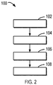
- FIG. 2 is a flowchart illustrating a method 100 for operating an air purifier 10 in a room in accordance with an embodiment of the present disclosure.
- the method 100 can be implemented by the controller 12 of the air purifier 10.
- the controller 12 can determine a volume of the room.
- the air purifier 10 may be operated at a first wind speed for a first period of time to decrease a concentration of the harmful gas.
- the first wind speed may be a maximum outlet wind speed of the air purifier 10 in order to reduce the pollutant concentration.
- the volume of the room may be determined based on a rate of decrease in the concentration of the harmful gas, the first wind speed, and the first period of time.
- the concentration C 0 may be chosen at the value which air purifier just finishes turbo mode operation and the concentration C 1 may be the criterion which trigger turbo mode.
- both the concentrations C 0 and C 1 could be obtained by averaging over a predefined period of time (for example, 20 minutes) in order to avoid effects from accidents like brought-in new furniture and open windows.
- the air purifier 10 triggers its turbo mode with maximum outlet wind speed Omax.
- the controller 12 can determine a releasing speed of a harmful gas in the room.
- the releasing speed of the harmful gas can be determined based on the volume of the room.
- the releasing speed can be the actual releasing speed in this room, taking into account of the effect of the air exchange between indoor and outdoor.
- the air purifier is operated at a second wind speed for a second period of time, such that a concentration of the harmful gas is increased from a first concentration to a second concentration.
- the releasing speed of the harmful gas may be then determined based on the volume of the room, the first concentration, the second concentration, the second wind speed, and the second period of time.
- V represents the volume of the room
- Co represents the first concentration
- C 1 represents the second concentration
- O 1 represents the second wind speed
- To represents the second period of time.
- the air purifier may work at an initial outlet wind speed O 1 , which may be the default value from its manufacture (if it is turned on the first time at this room, for example) or from the previous calculation (if the room information needs to be updated, for example).
- O 1 initial outlet wind speed
- the sensor on the purifier found that the pollutant concentration increase from C 0 to C 1 (C 1 >C 0 ).
- the process can be used to calculate the releasing speed as a function of the volume of the room based on equation (2).
- the fan 16 of the air purifier 10 may be stopped from running for a third period of time, such that a concentration of the harmful gas is increased from a first concentration to a second concentration.
- the releasing speed of the harmful gas may be then determined based on the volume of the room, the first concentration, the second concentration, and the second period of time.
- the controller 12 can obtain a target concentration of the harmful gas in the room.
- the target concentration may be predefined in the air purifier 10 and may be input by the user or operator of the air purifier 10.
- the controller 12 can determine a wind speed to operate the air purifier based on the releasing speed and the target concentration of the harmful gas.
- the air purifier 10 can keep using this speed for a while. If it is determined that a change of concentration of the harmful gas exceeds a threshold, the controller 12 can modify the releasing speed of the harmful gas in the room or trigger a new calculation of the releasing speed of the harmful gas in the room. For example, calculation of the new wind speed Ooptimal may be triggered when an increase of harmful gas concentration is found, which may mean that a new source is brought inside the room. The calculation of new wind speed Ooptimal may also be triggered when an obvious decrease of harmful gas concentration is found, which may mean some source is removed from the room.
- the controller 12 can modify or calculate the releasing speed of the harmful gas by a process similar to block 104.
- the controller 12 can adapt the wind speed of the air purifier based on the modified releasing speed of the harmful gas and the target concentration.
- a calculation of the new wind speed Ooptimal may also be triggered after a preset period since the last calculation.
- the preset period can be several months. This is for the situations like formaldehyde releasing speed changes, or some gas releasing source be changed, or filter purification efficiency changes.
- the wind speeds Ooptimal at daytime and night can be obtained separately, even if the air purifier is used at the same room during the day and night.
- the air exchange rate may be different during night, when the door is closed and curtain is open.
- users or operators may have different trade-offs between the noise and target pollution concentration for his sleep than during daytime.
- the outlet wind speed is more than necessary.
- releasing speed is equal to or less than zero in equation (3), which means the released harmful gas can be removed through the air exchange of that room, the smartphone could inform the customer to turn off the air purifier, or turn off the fan automatically.
- the method 100 can automatically adjust the outlet wind speed of the air purifier 10 to an optimal speed at customers' place.
- the indoor air pollution can be maintained at a desired level, without inducing unnecessary noise.
- this optimal outlet wind speed at auto mode can be customized in that it is different for different customers with different room size and different harmful gas releasing speed.
- the optimal outlet wind speed can also be adaptive in that it changes with the change of pollution source.
- the optimal outlet wind speed can also be personalized in that it can be set by customer on smartphone by trade-off between indoor pollutant concentration and fan noise.
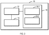
- FIG. 3 is a block diagram illustrating an air purifier 10 in accordance with another embodiment of the present disclosure.
- the detector 14 of the air purifier 10 may include a first sensor 14-1 configured to detect the concentration of a first pollutant and a second sensor 14-2 configured to detect a concentration of a second pollutant.
- the controller 12 can determine a respective target wind speed for the first and second pollutants. Both target wind speeds can be provided to the user for selection. Alternatively, a greater one of the target wind speeds can be identified as the wind speed to control the fan 16.
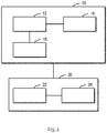
- FIG. 4 is a block diagram illustrating an air purifier system in accordance with another embodiment of the present disclosure.
- the air purifier system includes an air purifier 10 similar to the one as shown in FIG. 1 or 3 .
- an electronic device 20 is coupled to the air purifier 10 and can be configured to implement at least a part of method 100.
- the electronic device 20 includes a processor 22 and a memory 24 coupled to the processor 22 and storing instructions thereon, the instructions, when executed by the processor 22, performing the method 100.
- the electronic device 20 can be implemented by a mobile phone, a smart speaker, cloud, and/or the like.
- the electronic device 20 can be coupled to the air purifier 10 via a wired and wireless connection.
- the concentration measured by the detector 14 can be transmitted to the electronic device 20, which determines the wind speed to operate the air purifier 10.
- the determined wind speed can be transmitted back to the controller 12 to control the fan 16.
- the controller 12 can be implemented by a wind speed controller.
- various embodiments of the present disclosure may be implemented in hardware or special purpose circuits, software, logic or any combination thereof. Some aspects may be implemented in hardware, while other aspects may be implemented in firmware or software which may be executed by a controller, microprocessor or other computing device. While various aspects of embodiments of the present disclosure are illustrated and described as block diagrams, flowcharts, or using some other pictorial representation, it will be appreciated that the blocks, apparatus, systems, techniques or methods described herein may be implemented in, as non-limiting examples, hardware, software, firmware, special purpose circuits or logic, general purpose hardware or controller or other computing devices, or some combination thereof.
- embodiments of the present disclosure can be described in the general context of machine-executable instructions, such as those included in program modules, being executed in a device on a target real or virtual processor.
- program modules include routines, programs, libraries, objects, classes, components, data structures, or the like that perform particular tasks or implement particular abstract data types.
- the functionality of the program modules may be combined or split between program modules as desired in various embodiments.
- Machine-executable instructions for program modules may be executed within a local or distributed device. In a distributed device, program modules may be located in both local and remote storage media.
- Program code for carrying out methods of the present disclosure may be written in any combination of one or more programming languages. These program codes may be provided to a processor or controller of a general purpose computer, special purpose computer, or other programmable data processing apparatus, such that the program codes, when executed by the processor or controller, cause the functions/operations specified in the flowcharts and/or block diagrams to be implemented.
- the program code may execute entirely on a machine, partly on the machine, as a stand-alone software package, partly on the machine and partly on a remote machine or entirely on the remote machine or server.
- a machine readable medium may be any tangible medium that may contain, or store a program for use by or in connection with an instruction execution system, apparatus, or device.
- the machine readable medium may be a machine readable signal medium or a machine readable storage medium.
- a machine readable medium may include but not limited to an electronic, magnetic, optical, electromagnetic, infrared, or semiconductor system, apparatus, or device, or any suitable combination of the foregoing.
- machine readable storage medium More specific examples of the machine readable storage medium would include an electrical connection having one or more wires, a portable computer diskette, a hard disk, a random access memory (RAM), a read-only memory (ROM), an erasable programmable read-only memory (EPROM or Flash memory), an optical fiber, a portable compact disc read-only memory (CD-ROM), an optical storage device, a magnetic storage device, or any suitable combination of the foregoing.
- RAM random access memory
- ROM read-only memory
- EPROM or Flash memory erasable programmable read-only memory
- CD-ROM portable compact disc read-only memory
- magnetic storage device or any suitable combination of the foregoing.
Landscapes
- Engineering & Computer Science (AREA)
- Chemical & Material Sciences (AREA)
- Combustion & Propulsion (AREA)
- Mechanical Engineering (AREA)
- General Engineering & Computer Science (AREA)
- Physics & Mathematics (AREA)
- Signal Processing (AREA)
- Fluid Mechanics (AREA)
- Fuzzy Systems (AREA)
- Mathematical Physics (AREA)
- Ventilation (AREA)
- Air Conditioning Control Device (AREA)
Priority Applications (4)
| Application Number | Priority Date | Filing Date | Title |
|---|---|---|---|
| EP20839343.9A EP4085224A1 (fr) | 2019-12-30 | 2020-12-28 | Purificateur d'air et son procédé de fonctionnement |
| US17/790,483 US20230056122A1 (en) | 2019-12-30 | 2020-12-28 | Air purifier and method for operating the same |
| PCT/EP2020/087939 WO2021136759A1 (fr) | 2019-12-30 | 2020-12-28 | Purificateur d'air et son procédé de fonctionnement |
| CN202080091161.XA CN115298488A (zh) | 2019-12-30 | 2020-12-28 | 空气净化器及其操作方法 |
Applications Claiming Priority (1)
| Application Number | Priority Date | Filing Date | Title |
|---|---|---|---|
| CN2019130003 | 2019-12-30 |
Publications (1)
| Publication Number | Publication Date |
|---|---|
| EP3845820A1 true EP3845820A1 (fr) | 2021-07-07 |
Family
ID=69374174
Family Applications (2)
| Application Number | Title | Priority Date | Filing Date |
|---|---|---|---|
| EP20153994.7A Withdrawn EP3845820A1 (fr) | 2019-12-30 | 2020-01-28 | Purificateur d'air et procédé de fonctionnement correspondant |
| EP20839343.9A Withdrawn EP4085224A1 (fr) | 2019-12-30 | 2020-12-28 | Purificateur d'air et son procédé de fonctionnement |
Family Applications After (1)
| Application Number | Title | Priority Date | Filing Date |
|---|---|---|---|
| EP20839343.9A Withdrawn EP4085224A1 (fr) | 2019-12-30 | 2020-12-28 | Purificateur d'air et son procédé de fonctionnement |
Country Status (4)
| Country | Link |
|---|---|
| US (1) | US20230056122A1 (fr) |
| EP (2) | EP3845820A1 (fr) |
| CN (1) | CN115298488A (fr) |
| WO (1) | WO2021136759A1 (fr) |
Cited By (4)
| Publication number | Priority date | Publication date | Assignee | Title |
|---|---|---|---|---|
| CN114151916A (zh) * | 2021-11-22 | 2022-03-08 | 深圳市晨北科技有限公司 | 空气净化控制方法及装置、空气净化器及存储介质 |
| CN114440385A (zh) * | 2021-12-30 | 2022-05-06 | 合肥通用机械研究院有限公司 | 一种空气净化器转速控制方法 |
| CN116951578A (zh) * | 2023-06-20 | 2023-10-27 | 海信空调有限公司 | 空调器 |
| CN118274435A (zh) * | 2024-03-22 | 2024-07-02 | 青岛海尔空调器有限总公司 | 多房间分区净化空气的控制方法、控制装置和智能空调 |
Families Citing this family (2)
| Publication number | Priority date | Publication date | Assignee | Title |
|---|---|---|---|---|
| CN113865056B (zh) * | 2021-10-23 | 2022-09-27 | 宁波爱科特环境电器有限公司 | 一种空气净化方法、系统、存储介质及智能终端 |
| CN119665386B (zh) * | 2024-12-19 | 2025-07-04 | 东莞丽之健电子科技有限公司 | 一种空气净化器的节能控制方法、装置及系统 |
Citations (4)
| Publication number | Priority date | Publication date | Assignee | Title |
|---|---|---|---|---|
| WO2017186606A1 (fr) * | 2016-04-27 | 2017-11-02 | Koninklijke Philips N.V. | Purificateur d'air et parfumage d'ambiance |
| CN109268944A (zh) * | 2018-09-06 | 2019-01-25 | 广东美的制冷设备有限公司 | 空气调节器及其控制方法、装置和计算机可读存储介质 |
| CN105757909B (zh) * | 2016-04-19 | 2019-03-29 | 九阳股份有限公司 | 一种空气净化器自动控制方法 |
| WO2019213998A1 (fr) * | 2018-05-07 | 2019-11-14 | 大连理工大学 | Dispositif et procédé de purification et d'élimination de pollution intérieure de type à localisation de source automatique |
Family Cites Families (7)
| Publication number | Priority date | Publication date | Assignee | Title |
|---|---|---|---|---|
| WO2006016345A1 (fr) * | 2004-08-11 | 2006-02-16 | Koninklijke Philips Electronics N.V. | Systeme de detection de la pollution atmospherique |
| CN106338105B (zh) * | 2015-07-08 | 2020-04-10 | 松下知识产权经营株式会社 | 吸气装置以及吸气方法 |
| CN105276687B (zh) * | 2015-11-24 | 2018-12-18 | 珠海格力电器股份有限公司 | 空气净化器的清洗提示系统及清洗提示方法、空气净化器 |
| JP2016217706A (ja) * | 2016-08-30 | 2016-12-22 | 三菱電機株式会社 | 空気清浄機 |
| KR102024565B1 (ko) * | 2017-04-20 | 2019-09-24 | 엘지전자 주식회사 | 먼지 측정 장치 및 방법 |
| KR102514293B1 (ko) * | 2018-06-15 | 2023-03-27 | 쿠쿠홈시스 주식회사 | 공기 청정 장치 |
| CN110207324B (zh) * | 2019-05-30 | 2020-09-04 | 浙江越芬科技有限公司 | 动态通风控制方法和系统 |
-
2020
- 2020-01-28 EP EP20153994.7A patent/EP3845820A1/fr not_active Withdrawn
- 2020-12-28 US US17/790,483 patent/US20230056122A1/en not_active Abandoned
- 2020-12-28 WO PCT/EP2020/087939 patent/WO2021136759A1/fr not_active Ceased
- 2020-12-28 CN CN202080091161.XA patent/CN115298488A/zh active Pending
- 2020-12-28 EP EP20839343.9A patent/EP4085224A1/fr not_active Withdrawn
Patent Citations (4)
| Publication number | Priority date | Publication date | Assignee | Title |
|---|---|---|---|---|
| CN105757909B (zh) * | 2016-04-19 | 2019-03-29 | 九阳股份有限公司 | 一种空气净化器自动控制方法 |
| WO2017186606A1 (fr) * | 2016-04-27 | 2017-11-02 | Koninklijke Philips N.V. | Purificateur d'air et parfumage d'ambiance |
| WO2019213998A1 (fr) * | 2018-05-07 | 2019-11-14 | 大连理工大学 | Dispositif et procédé de purification et d'élimination de pollution intérieure de type à localisation de source automatique |
| CN109268944A (zh) * | 2018-09-06 | 2019-01-25 | 广东美的制冷设备有限公司 | 空气调节器及其控制方法、装置和计算机可读存储介质 |
Cited By (5)
| Publication number | Priority date | Publication date | Assignee | Title |
|---|---|---|---|---|
| CN114151916A (zh) * | 2021-11-22 | 2022-03-08 | 深圳市晨北科技有限公司 | 空气净化控制方法及装置、空气净化器及存储介质 |
| CN114440385A (zh) * | 2021-12-30 | 2022-05-06 | 合肥通用机械研究院有限公司 | 一种空气净化器转速控制方法 |
| CN114440385B (zh) * | 2021-12-30 | 2023-07-14 | 合肥通用机械研究院有限公司 | 一种空气净化器转速控制方法 |
| CN116951578A (zh) * | 2023-06-20 | 2023-10-27 | 海信空调有限公司 | 空调器 |
| CN118274435A (zh) * | 2024-03-22 | 2024-07-02 | 青岛海尔空调器有限总公司 | 多房间分区净化空气的控制方法、控制装置和智能空调 |
Also Published As
| Publication number | Publication date |
|---|---|
| EP4085224A1 (fr) | 2022-11-09 |
| US20230056122A1 (en) | 2023-02-23 |
| WO2021136759A1 (fr) | 2021-07-08 |
| CN115298488A (zh) | 2022-11-04 |
Similar Documents
| Publication | Publication Date | Title |
|---|---|---|
| EP3845820A1 (fr) | Purificateur d'air et procédé de fonctionnement correspondant | |
| CN109268943B (zh) | 空气调节器及其控制方法、装置和计算机可读存储介质 | |
| EP3187241B1 (fr) | Procédé et dispositif de calcul de la durée de vie consommée | |
| US11633687B2 (en) | Air purifier | |
| CN109268944B (zh) | 空气调节器及其控制方法、装置和计算机可读存储介质 | |
| CN109268946B (zh) | 空气调节器及其控制方法、装置和计算机可读存储介质 | |
| EP3707439B1 (fr) | Purification d'air intelligente | |
| CN114857719A (zh) | 用于房间的空气管理的设备和方法 | |
| CN105757909B (zh) | 一种空气净化器自动控制方法 | |
| US11002459B2 (en) | Control device and operating method for air treatment apparatuses | |
| KR101968567B1 (ko) | 환기시스템의 필터교체시점 알림장치 | |
| EP3567323A1 (fr) | Purification d'air intelligente | |
| CN108105865B (zh) | 空调器的控制方法和空调器 | |
| CN111964211A (zh) | 空气净化控制方法、装置及空气净化设备 | |
| CN113587315A (zh) | 空气净化控制方法、装置、控制器、介质及空气净化器 | |
| KR101778736B1 (ko) | 공기 청정기의 제어 방법 및 장치 | |
| KR20170042036A (ko) | 환기시스템의 필터교체시점 알림장치 및 알림방법 | |
| CN113565551B (zh) | 自动增益控制的矿井通风方法、装置及系统 | |
| CN117515829A (zh) | 空调控制方法、装置、空调器及存储介质 | |
| JP2025025270A (ja) | 風量制御システム、レンジフード、制御装置、およびコンピュータプログラム | |
| US12270572B2 (en) | Systems and methods for controlling indoor air quality with a fluid moving apparatus | |
| CN116123657A (zh) | 智能家居系统的控制方法及系统、计算机设备 | |
| JP2024000157A (ja) | 制御装置及び送風装置 | |
| KR102749151B1 (ko) | 인공지능 기술기반 공기 청정 시스템 및 방법 | |
| CN117249566A (zh) | 空气处理设备的控制方法、装置、空调器及存储介质 |
Legal Events
| Date | Code | Title | Description |
|---|---|---|---|
| PUAI | Public reference made under article 153(3) epc to a published international application that has entered the european phase |
Free format text: ORIGINAL CODE: 0009012 |
|
| STAA | Information on the status of an ep patent application or granted ep patent |
Free format text: STATUS: THE APPLICATION HAS BEEN PUBLISHED |
|
| AK | Designated contracting states |
Kind code of ref document: A1 Designated state(s): AL AT BE BG CH CY CZ DE DK EE ES FI FR GB GR HR HU IE IS IT LI LT LU LV MC MK MT NL NO PL PT RO RS SE SI SK SM TR |
|
| STAA | Information on the status of an ep patent application or granted ep patent |
Free format text: STATUS: THE APPLICATION IS DEEMED TO BE WITHDRAWN |
|
| 18D | Application deemed to be withdrawn |
Effective date: 20220108 |