EP3845906A1 - Dispositif et méthode d'analyse automatique - Google Patents
Dispositif et méthode d'analyse automatique Download PDFInfo
- Publication number
- EP3845906A1 EP3845906A1 EP19854610.3A EP19854610A EP3845906A1 EP 3845906 A1 EP3845906 A1 EP 3845906A1 EP 19854610 A EP19854610 A EP 19854610A EP 3845906 A1 EP3845906 A1 EP 3845906A1
- Authority
- EP
- European Patent Office
- Prior art keywords
- measurement
- analysis
- reaction
- measurement item
- schedule
- Prior art date
- Legal status (The legal status is an assumption and is not a legal conclusion. Google has not performed a legal analysis and makes no representation as to the accuracy of the status listed.)
- Granted
Links
Images




Classifications
-
- G—PHYSICS
- G01—MEASURING; TESTING
- G01N—INVESTIGATING OR ANALYSING MATERIALS BY DETERMINING THEIR CHEMICAL OR PHYSICAL PROPERTIES
- G01N35/00—Automatic analysis not limited to methods or materials provided for in any single one of groups G01N1/00 - G01N33/00; Handling materials therefor
- G01N35/00584—Control arrangements for automatic analysers
- G01N35/0092—Scheduling
- G01N35/0095—Scheduling introducing urgent samples with priority, e.g. Short Turn Around Time Samples [STATS]
-
- G—PHYSICS
- G01—MEASURING; TESTING
- G01N—INVESTIGATING OR ANALYSING MATERIALS BY DETERMINING THEIR CHEMICAL OR PHYSICAL PROPERTIES
- G01N35/00—Automatic analysis not limited to methods or materials provided for in any single one of groups G01N1/00 - G01N33/00; Handling materials therefor
- G01N2035/00346—Heating or cooling arrangements
- G01N2035/00356—Holding samples at elevated temperature (incubation)
-
- G—PHYSICS
- G01—MEASURING; TESTING
- G01N—INVESTIGATING OR ANALYSING MATERIALS BY DETERMINING THEIR CHEMICAL OR PHYSICAL PROPERTIES
- G01N35/00—Automatic analysis not limited to methods or materials provided for in any single one of groups G01N1/00 - G01N33/00; Handling materials therefor
- G01N35/00584—Control arrangements for automatic analysers
- G01N35/0092—Scheduling
- G01N2035/0094—Scheduling optimisation; experiment design
Definitions
- the present invention relates to an automatic analyzer and a method thereof.
- An automatic analyzer that analyzes biological samples such as blood and urine with a reagent typically has a measurement sequence including a series of operations such as sample sampling, addition of reagents, stirring, incubation, and measurement of an electrical signal for analyzing a target component in a sample, and sequentially analyzes a plurality of measurement items in parallel by shifting a start timing of the measurement sequence by a fixed time and starting the measurement sequence discretely.
- Patent Literature 1 shows an example of such an automatic analyzer. Normally, one type of the automatic analyzer has a corresponding measurement sequence.
- an automatic analyzer that enables a plurality of different measurement sequences to be operated by one automatic analyzer in order to prevent a decrease in a throughput.
- Such an automatic analyzer has a check function to avoid a duplicate use and an operation interference of mechanical equipment, has a plurality of operation methods for a transport mechanism to transport a reaction container to the mechanical equipment, and switches these operation methods as necessary.
- An example of such an automatic analyzer is shown in Patent Literature 2.
- an analyzer in the related art enables the plurality of different measurement sequences to be operated as described above, has a check function of avoiding the duplicate use and the operation interference of the mechanical equipment, has a plurality of operation methods for the transport mechanism to transport the reaction container to the mechanical equipment, and switches these operation methods as necessary to perform measurement.
- a turnaround time of the measurement sequence 2 becomes T1 which is the same as that of the measurement sequence 1 and deteriorates. Accordingly, even in a measurement sequence in which a measurement result can be obtained in half the time, a turnaround time as in the related art may be required, which is a problem to be solved.
- an object of the invention is to provide an automatic analyzer capable of efficiently measuring a plurality of measurement items having different incubation time and capable of preventing deterioration of a turnaround time of a measurement, and a method thereof.
- the invention provides an automatic analyzer including: an incubator that includes a plurality of holding portions holding a plurality of reaction containers and promotes a reaction of a mixed solution of a sample and a reagent, the reaction containers containing the mixed solution; a receiving unit that receives analysis information relating to a measurement item of the sample; a transport unit that transports each of the reaction containers to the holding portion; an analyzing unit that performs analysis by operating a measurement sequence of a predetermined reaction time on each of the reaction containers containing the mixed solution to which a predetermined reagent is added at a predetermined timing based on the analysis information; a planning unit that creates an analysis schedule to be performed by the analyzing unit based on the analysis information, wherein in an analysis of a plurality of different measurement items, the planning unit estimates and creates the analysis schedule according to a plurality of different measurement sequences such that the different measurement sequences are capable of being performed.
- the invention provides an automatic analysis method of an automatic analyzer, the automatic analyzer including: an incubator that includes a plurality of holding portions holding a plurality of reaction containers and promotes a reaction of a mixed solution of a sample and a reagent, the reaction containers containing the mixed solution; and an analyzing unit that performs analysis on the mixed solution contained in each of the reaction containers by installing the reaction container, in which the predetermined reagent is added to the sample at a predetermined timing based on analysis information relating to a measurement item of the sample, in the holding portion and operating a measurement sequence at a predetermined reaction time, wherein in a case where an analysis schedule to be performed by the analyzing unit based on analysis information of the sample that is requested to be measured is created, in order to analyze a plurality of different measurement items, an analysis schedule of an analysis target is estimated and created according to a plurality of different measurement sequences of the measurement items such that the different measurement sequences are capable of being performed.
- a turnaround time of a short measurement item can be shortened by scheduling an empty cycle, which can contribute to early diagnosis.
- a short measurement item that requires a short period of time for a reaction
- a standard measurement item that requires a standard period of time for a reaction
- the latter may be called a normal item.
- the first embodiment is an embodiment of an automatic analyzer including: an incubator that includes a plurality of holding portions holding a plurality of reaction containers and promotes a reaction of a mixed solution of a sample and a reagent, the reaction containers containing the mixed solution; a receiving unit that receives analysis information relating to a measurement item of the sample; a transport unit that transports each of the reaction containers to the holding portion; an analyzing unit that performs analysis by operating a measurement sequence of a predetermined reaction time on each of the reaction containers containing the mixed solution to which a predetermined reagent is added at a predetermined timing based on the analysis information; a planning unit that creates an analysis schedule to be performed by the analyzing unit based on the analysis information.
- the planning unit estimates and creates the analysis schedule according to a plurality of different measurement sequences such that the different measurement sequences are capable of being performed.
- the first embodiment is an embodiment of an automatic analysis method of an automatic analyzer, the automatic analyzer including: an incubator that includes a plurality of holding portions holding a plurality of reaction containers and promotes a reaction of a mixed solution of a sample and a reagent, the reaction containers containing the mixed solution; and an analyzing unit that performs analysis on the mixed solution contained in each of the reaction containers by installing the reaction container, in which the predetermined reagent is added to the sample at a predetermined timing based on analysis information relating to a measurement item of the sample, in the holding portion and operating a measurement sequence at a predetermined reaction time.
- an incubator that includes a plurality of holding portions holding a plurality of reaction containers and promotes a reaction of a mixed solution of a sample and a reagent, the reaction containers containing the mixed solution
- an analyzing unit that performs analysis on the mixed solution contained in each of the reaction containers by installing the reaction container, in which the predetermined reagent is added to the sample at a predetermined timing based on analysis information
- an analysis schedule to be performed by the analyzing unit based on analysis information of the sample that is requested to be measured is created, in order to analyze a plurality of different measurement items, an analysis schedule of an analysis target is estimated and created according to a plurality of different measurement sequences of the measurement items such that the different measurement sequences are capable of being performed.
- Fig. 1 is a system block diagram illustrating an overall configuration example of an automatic analyzer according to the first embodiment.
- the automatic analyzer includes a sample rack loading unit 1-1, an identifier (ID) reading unit 1-2, a transport line 1-3, a reexamination transport line 1-4, an analysis module 1-7, a sample rack collecting unit 1-5, and a computer for overall management 1-8.
- ID identifier
- the automatic analyzer includes a sample rack loading unit 1-1, an identifier (ID) reading unit 1-2, a transport line 1-3, a reexamination transport line 1-4, an analysis module 1-7, a sample rack collecting unit 1-5, and a computer for overall management 1-8.
- the sample rack loading unit 1-1 is a unit that loads a plurality of sample racks into the automatic analyzer.
- a calibrator storing unit 1-6 is a mechanism that can store a reagent used for calibration and automatically load a calibrator upon a request.
- the analysis module 1-7 is located along the transport line 1-3 and is detachably connected to the transport line 1-3.
- the analysis module 1-7 includes a computer 1-10 for an analysis module that functions as a control unit that performs a necessary processing control inside thereof.
- the sample rack loading unit 1-1 includes a computer 1-9 that performs a necessary control on the sample rack loading unit 1-1, the transport line 1-3, the reexamination transport line 1-4 and the sample rack collecting unit 1-5.
- These computers 1-9 and 1-10, and the ID reading unit 1-2 are connected to the computer for overall management 1-8.
- the computer for overall management 1-8 is connected to an operation unit 1-12 that inputs further necessary information, a display unit 1-11 that displays an analysis result, and an external network 1-13.
- the computer for overall management 1-8, and the computers 1-9 and 1-10 each have a normal computer configuration, and include a central processing unit (CPU), a storage unit (memory), an input/output unit, a network interface, etc.
- the computer for overall management 1-8 and the computers 1-9 and 1-10 may implement functions of all control units with one computer without preparing three independent computers.
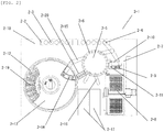
- a configuration example of the analysis module of the present embodiment will be described with reference to Fig. 2 .
- a rack 2-2 on which a sample container 2-3 for holding a sample is erected, is moved by a rack transport line 2-18 to a sample dispensing position near a sample dispensing nozzle 2-4.
- An incubator 2-5 is installed with a plurality of reaction containers 2-6, and has a configuration capable of rotational movement for moving each of the reaction containers 2-6 installed in the circumferential direction to a predetermined position.
- a sample dispensing tip and reaction container transport mechanism 2-7 can move in three directions of an X-axis, a Y-axis, and a Z-axis, and move within a predetermined range of a sample dispensing tip and reaction container holder member 2-8, a reaction container stirring mechanism 2-9, a sample dispensing tip and reaction container waste hole 2-10, and a sample dispensing tip mounting position 2-11, and the incubator 2-5 to transport a sample dispensing tip and a reaction container.
- a plurality of unused reaction containers and sample dispensing tips are installed on the sample dispensing tip and reaction container holder member 2-8.
- the sample dispensing tip and reaction container transport mechanism 2-7 moves to above the sample dispensing tip and reaction container holder member 2-8 and descends in the Z direction to grip an unused reaction container, and then rises and further moves to a predetermined position above the incubator 2-5, and descends to install the reaction container 2-6 at a corresponding position.
- sample dispensing tip and reaction container transport mechanism 2-7 moves to above the sample dispensing tip and reaction container holder member 2-8 and descends to grip an unused sample dispensing tip, and then rises and moves to above the sample dispensing tip mounting position 2-11, and descends to install the sample dispensing tip at a corresponding position.
- the sample dispensing nozzle 2-4 can rotate and move up and down, and rotates and moves to above the sample dispensing tip mounting position 2-11, and then descends to press-fit and load the sample dispensing tip into a tip of the sample dispensing nozzle 2-4.
- the sample dispensing nozzle 2-4 loaded with the sample dispensing tip moves to above the sample container 2-3 mounted on the transport rack 2-2, and then descends to aspirate a predetermined amount of a sample held in the sample container 2-3.
- the sample dispensing nozzle 2-4 that aspirated the sample moves to above the incubator 2-5, and then descends to discharge the aspirated sample into an unused reaction container 2-6 held in the incubator 2-5.
- the sample dispensing nozzle 2-4 moves to above the sample dispensing tip and reaction container waste hole 2-10, and drops an used sample dispensing tip into a disposal hole and discards it.
- a plurality of reagent containers 2-19 are installed on a reagent disk 2-12.
- a reagent disk cover 2-13 is provided above the reagent disk 2-12, and an inside of the reagent disk 2-12 is kept at a predetermined temperature.
- a reagent disk cover opening portion 2-14 is provided in a part of the reagent disk cover 2-13.
- a reagent dispensing nozzle 2-15 can rotate and move up and down, and rotates and moves to above the opening portion 2-14 of the reagent disc cover 2-13 and descends to immerse a tip of the reagent dispensing nozzle 2-15 in a reagent in a predetermined reagent container 2-19 to aspirate a predetermined amount of the reagent. Then, the reagent dispensing nozzle 2-15 rises, and then rotates and moves to a predetermined position above the incubator 2-5 to discharge an aspirated reagent into the predetermined reaction container 2-6.
- the reaction container 2-6 to which the sample and the reagent are discharged is moved to a predetermined position by rotation of the incubator 2-5, and is transported to the reaction container stirring mechanism 2-9 by the sample dispensing tip and reaction container transport mechanism 2-7.
- the reaction container stirring mechanism 2-9 stirs and mixes the sample and the reagent in the reaction container by applying a rotary motion to the reaction container 2-6.
- the reaction container 2-6 after stirring is returned to a predetermined position of the incubator 2-5 by the sample dispensing tip and reaction container transport mechanism 2-7.
- a reaction solution aspiration nozzle 2-16 can rotate and move up and down, and moves to above the reaction container 2-6 after the sample and the reagent are dispensed and stirred and a predetermined reaction time has passed in the incubator 2-5, and descends and aspirates a reaction solution in the reaction container 2-6.
- the reaction solution aspirated by the reaction solution aspiration nozzle 2-16 is analyzed by at least one detecting unit 2-17.
- the reaction container 2-6 from which the reaction solution is aspirated is moved to a predetermined position by the rotation of the incubator 2-5, and is moved from the incubator 2-5 to above the sample dispensing tip and reaction container waste hole 2-10 by the sample dispensing tip and reaction container transport mechanism 2-7, and then is discarded from the disposal hole.
- operation patterns such as one position clockwise and three positions counterclockwise may be prepared as operation patterns of the incubator 2-5, for example, as shown in Fig. 5 of Patent Literature 2.
- Fig. 3 is a block diagram illustrating various functions of the computer 1-10 for the analysis module in the present embodiment. These various functions can be implemented by the central processing unit (CPU) built in the computer that executes a predetermined program stored in the storage unit, etc. Arrows in the figure denote a transmission direction of information between functional blocks. Information transmission is, for example, message communication.
- a request input unit 3-1 has a function in which the analysis module 2-1 shown in Fig. 2 receives a measurement request for a sample on a sample rack.
- a rack managing unit 3-2 manages the measurement request received by an input unit 3-1.
- a planning unit 3-3 schedules a measurement of the sample in analysis module 2-1.
- a mechanism control unit 3-4 operates various mechanisms of the analysis module according to the schedule planned by the planning unit 3-3.
- a result output unit 3-5 notifies a host system such as the computer for overall management 1-8 of a measurement result corresponding to the measurement request.
- a request analyzing unit 3-6 receives the measurement request input to the request input unit 3-1, classifies whether the measurement item is a short measurement item or a standard measurement item, and obtains a ratio of the short measurement item and the standard measurement item in the measurement request. Here, the ratio is a proportion of the short measurement item to the standard measurement item.
- Unique functions of the automatic analyzer of the present embodiment are functions of the request analyzing unit 3-6 and the planning unit 3-3 in Fig. 3 .
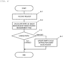
- Fig. 4 is a flowchart illustrating processing flows of the request analyzing unit 3-6.
- the measurement request is received from the request input unit 3-1 (step 4-1).
- a measurement item of a measurement sequence of the received measurement request is a short measurement item or a standard measurement item, and based on a result thereof, the ratio of the short measurement item and the standard measurement item is calculated (step 4-2) . Then, it is confirmed whether the calculated ratio has changed (step 4-3), and if there is a change, the ratio is recorded as an empty cycle setting for the short measurement, and the empty cycle setting for the short measurement is updated (step 4-4) . If there is no change, the processing flows end immediately and wait for a next request reception. By updating this setting, the request analyzing unit 3-6 outputs an updated empty cycle ratio for the short measurement.
- an empty cycle means a cycle without measurement in the analysis schedule, and a cycle set to shorten a turnaround time of a STAT item is referred to as an empty cycle for the short measurement.
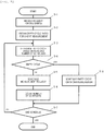
- Fig. 5 is a flowchart illustrating processing flows of the planning unit 3-3.
- a measurement request collated with the rack 2-2 is received from the rack managing unit 3-2 (step 5-1).
- the above-mentioned empty cycle ratio for the short measurement which is an analysis result of the processing flows shown in Fig. 4 of the request analyzing unit 3-6, is acquired (step 5-2).
- it is determined whether a next analysis schedule is an empty cycle (step 5-3).
- next analysis schedule is an empty cycle (yes in step 5-4), the empty cycle for the short measurement is scheduled (step 5-8). If the next analysis schedule is not an empty cycle (no), a measurement item based on the measurement request is scheduled (step 5-5) and the number of the schedules in the analysis schedule is counted up (step 5-6). Then, it is confirmed whether all schedules of received measurement requests have been completed (step 5-7), and if it has been not completed (no), the same process is executed from step 5-3 to process a next schedule. If all the schedules of the received measurement requests have been completed (yes), the processing flows end.
- Fig. 6 shows a comparison of measurement sequences of an automatic analyzer in the related art and the automatic analyzer of the present embodiment in upper and lower stages. That is, Fig. 6 is an example of, when a measurement item A which is a standard measurement item is measured continuously, comparing an elapsed time until a measurement result of a measurement item B which is a short measurement item is output when an empty cycle without measurement is scheduled according to the configuration of the present embodiment with an elapsed time according to the related art when the measurement item B which is the short measurement item is measured. In both cases, an examination request contains 5 items, examination 1 to examination 5. Contents of analysis processes a to e of the measurement items A and B are shown in a lower right portion.
- the measurement item A shown in Fig. 6 is an example of the measurement sequence of the standard measurement item
- the measurement item B is an example of the measurement sequence of the short measurement item.
- b denotes first-stage reagent aspiration/addition
- c denotes magnetic particle reagent aspiration/addition
- d denotes reaction solution stirring
- e denotes electrical signal measurement
- f and g denote incubation.
- the measurement sequences of the measurement item A and measurement item B are configured.
- z denotes empty cycle (no measurement).
- One operation of the analysis processes a to e cannot be operated at the same timing for a plurality of measurement items.
- the measurement item B of the examination 4 can start the measurement from time 5 earlier than time 6 on the horizontal axis, and thus an elapsed time t2 until the measurement result of the measurement item B is output is shorter than an elapsed time t1 in the case of the related art (t2 ⁇ t1).
- the automatic analyzer and the automatic analysis method of the present embodiment can shorten the turnaround time of the short measurement item and contribute to an early diagnosis.
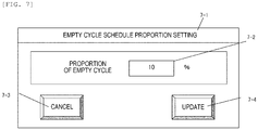
- Fig. 7 is an example of an empty cycle schedule proportion setting screen.
- a proportion of an empty cycle can be input in a text box 7-2 using a cancel button 7-3 and an update button 7-4. It is also possible to determine the empty cycle schedule proportion based on a condition of the proportion (%) of the empty cycle set on a GUI screen regardless of instructions from the computer for overall management 1-8.
- Fig. 8 is an example of an empty cycle schedule priority setting screen.
- a priority condition in a priority condition 8-2 is selected by a condition selection radio button 8-3. It is also possible to determine whether to prioritize an empty cycle schedule based on the priority condition set by a user on such a GUI screen regardless of the instructions from the computer for overall management 1-8.
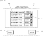
- Fig. 9 is an example of an empty cycle schedule presence/absence setting screen for each measurement item.
- a measurement item name 9-2 On an empty cycle schedule presence/absence setting screen 9-2, a measurement item name 9-2, a combo box for selection 9-3, a cancel button 9-4, and an update button 9-5 are displayed.
- measurement item name 9-2 measurement items A to E can be selected. In this way, presence/absence of empty cycle schedules for the measurement items may be determined based on conditions set on such a GUI screen regardless of the instructions of the computer for overall management 1-8.
- the analysis module serving as the analyzing unit includes a plurality of detection units 2-17 that operate the measurement sequence to perform analysis, and can set the analysis schedule for different measurement sequences for each of the plurality of detection units. That is, different analysis schedules can be set for a first reaction container to be transported to a first detecting unit and a second reaction container to be transported to a second detecting unit. For example, an analysis schedule may be set for the first reaction container and no analysis schedule may be set for the second reaction container.
- the number of physical detection units in the analysis module is not limited, and the first detecting unit and the second detecting unit may be logically assigned and different analysis schedules may be set for each.
- the analyzing unit of the automatic analyzer includes the plurality of detection units, it is possible to specify that the analysis schedule of the different measurement sequences is executed for each of the plurality of detecting units, and contents of the specified measurement sequences are saved in the storage unit of the computer 1-10.
Landscapes
- Physics & Mathematics (AREA)
- Health & Medical Sciences (AREA)
- Life Sciences & Earth Sciences (AREA)
- Chemical & Material Sciences (AREA)
- Analytical Chemistry (AREA)
- Biochemistry (AREA)
- General Health & Medical Sciences (AREA)
- General Physics & Mathematics (AREA)
- Immunology (AREA)
- Pathology (AREA)
- Automatic Analysis And Handling Materials Therefor (AREA)
Applications Claiming Priority (2)
| Application Number | Priority Date | Filing Date | Title |
|---|---|---|---|
| JP2018158977 | 2018-08-28 | ||
| PCT/JP2019/026440 WO2020044781A1 (fr) | 2018-08-28 | 2019-07-03 | Dispositif et méthode d'analyse automatique |
Publications (3)
| Publication Number | Publication Date |
|---|---|
| EP3845906A1 true EP3845906A1 (fr) | 2021-07-07 |
| EP3845906A4 EP3845906A4 (fr) | 2022-05-25 |
| EP3845906B1 EP3845906B1 (fr) | 2025-06-04 |
Family
ID=69642953
Family Applications (1)
| Application Number | Title | Priority Date | Filing Date |
|---|---|---|---|
| EP19854610.3A Active EP3845906B1 (fr) | 2018-08-28 | 2019-07-03 | Dispositif et méthode d'analyse automatique |
Country Status (5)
| Country | Link |
|---|---|
| US (1) | US12216134B2 (fr) |
| EP (1) | EP3845906B1 (fr) |
| JP (1) | JP7179861B2 (fr) |
| CN (1) | CN112567249B (fr) |
| WO (1) | WO2020044781A1 (fr) |
Families Citing this family (2)
| Publication number | Priority date | Publication date | Assignee | Title |
|---|---|---|---|---|
| JP7529663B2 (ja) * | 2019-06-24 | 2024-08-06 | 積水メディカル株式会社 | 自動分析装置 |
| US12584933B2 (en) * | 2019-12-26 | 2026-03-24 | Hitachi High-Tech Corporation | Automatic analyzer and control program for automatic analyzer |
Family Cites Families (29)
| Publication number | Priority date | Publication date | Assignee | Title |
|---|---|---|---|---|
| US4052161A (en) * | 1974-08-22 | 1977-10-04 | The Perkin-Elmer Corporation | Kinetic analyzer |
| US4134678A (en) * | 1977-03-16 | 1979-01-16 | Instrumentation Laboratory Inc. | Automatic blood analysis apparatus and method |
| JPH03502737A (ja) * | 1988-11-08 | 1991-06-20 | アプライド・バイオシステムズ,インコーポレーテッド | アッセイオメイト |
| JPH03107766A (ja) * | 1989-09-20 | 1991-05-08 | Fujitsu Ltd | 臨床検査装置 |
| JPH04372859A (ja) * | 1991-06-21 | 1992-12-25 | Shimadzu Corp | 自動分析装置 |
| JP2908923B2 (ja) | 1991-12-18 | 1999-06-23 | 日本電子株式会社 | 生化学自動分析装置 |
| JP2616360B2 (ja) * | 1992-09-30 | 1997-06-04 | 株式会社島津製作所 | 血液凝固分析装置 |
| JP2798080B2 (ja) * | 1997-04-04 | 1998-09-17 | 株式会社日立製作所 | 自動分析装置 |
| US20030040117A1 (en) * | 2001-07-27 | 2003-02-27 | Devlin William Jackson | Increasing throughput in an automatic clinical analyzer by partitioning assays according to type |
| US7015042B2 (en) * | 2001-07-27 | 2006-03-21 | Dade Behring Inc. | Increasing throughput in an automatic clinical analyzer by partitioning assays according to type |
| CN105258988A (zh) | 2002-06-20 | 2016-01-20 | 徕卡病理系统墨尔本控股有限公司 | 带有排放机构的生物反应装置 |
| JP2004279289A (ja) * | 2003-03-18 | 2004-10-07 | Hitachi High-Technologies Corp | 自動分析装置 |
| JPWO2008050396A1 (ja) * | 2006-10-24 | 2010-02-25 | オリンパス株式会社 | 分析装置 |
| JP5255265B2 (ja) * | 2007-12-18 | 2013-08-07 | ベックマン コールター, インコーポレイテッド | 洗浄装置および自動分析装置 |
| JP5530609B2 (ja) * | 2008-09-05 | 2014-06-25 | 株式会社日立ハイテクノロジーズ | 前処理装置及びそれを備えた質量分析装置 |
| JP5260267B2 (ja) | 2008-12-26 | 2013-08-14 | 株式会社日立ハイテクノロジーズ | 自動分析装置 |
| JP2011232249A (ja) * | 2010-04-28 | 2011-11-17 | Toshiba Corp | 自動分析装置 |
| CN104024861B (zh) * | 2012-01-05 | 2015-11-25 | 株式会社日立高新技术 | 自动分析装置以及自动分析装置中的试剂处理方法 |
| CN104508493B (zh) * | 2012-07-25 | 2016-07-06 | 株式会社日立高新技术 | 自动分析装置 |
| JP6047385B2 (ja) * | 2012-11-29 | 2016-12-21 | 株式会社日立ハイテクノロジーズ | 自動分析装置 |
| JP6161909B2 (ja) * | 2013-01-29 | 2017-07-12 | 株式会社日立ハイテクノロジーズ | 自動分析装置 |
| JP6180788B2 (ja) * | 2013-05-20 | 2017-08-16 | 株式会社日立ハイテクノロジーズ | 自動分析装置および分析方法 |
| JP6666628B2 (ja) * | 2016-09-08 | 2020-03-18 | 株式会社日立ハイテク | 自動分析装置 |
| WO2018168431A1 (fr) * | 2017-03-14 | 2018-09-20 | 株式会社日立ハイテクノロジーズ | Système d'analyse automatisé |
| WO2018179081A1 (fr) * | 2017-03-28 | 2018-10-04 | 株式会社日立ハイテクノロジーズ | Dispositif d'inspection |
| CN111033267B (zh) * | 2017-08-09 | 2023-10-27 | 株式会社日立高新技术 | 自动分析装置 |
| CN111094994B (zh) * | 2017-09-13 | 2023-05-30 | 株式会社日立高新技术 | 自动分析装置 |
| EP3677916B1 (fr) * | 2018-01-26 | 2023-07-12 | Hitachi High-Tech Corporation | Analyseur automatisé |
| CN111201439B (zh) * | 2018-02-26 | 2024-04-05 | 株式会社日立高新技术 | 自动分析装置 |
-
2019
- 2019-07-03 EP EP19854610.3A patent/EP3845906B1/fr active Active
- 2019-07-03 JP JP2020540112A patent/JP7179861B2/ja active Active
- 2019-07-03 CN CN201980053099.2A patent/CN112567249B/zh active Active
- 2019-07-03 WO PCT/JP2019/026440 patent/WO2020044781A1/fr not_active Ceased
- 2019-07-03 US US17/267,148 patent/US12216134B2/en active Active
Also Published As
| Publication number | Publication date |
|---|---|
| US12216134B2 (en) | 2025-02-04 |
| EP3845906A4 (fr) | 2022-05-25 |
| WO2020044781A1 (fr) | 2020-03-05 |
| EP3845906B1 (fr) | 2025-06-04 |
| US20220011326A1 (en) | 2022-01-13 |
| CN112567249A (zh) | 2021-03-26 |
| CN112567249B (zh) | 2024-08-13 |
| JP7179861B2 (ja) | 2022-11-29 |
| JPWO2020044781A1 (ja) | 2021-08-26 |
Similar Documents
| Publication | Publication Date | Title |
|---|---|---|
| JP6008877B2 (ja) | 自動分析装置および自動分析装置における試薬処理方法 | |
| US20180080949A1 (en) | Automated scheduler for laboratory equipment | |
| US8329103B2 (en) | Sample analyzer and method for analyzing samples | |
| CN102265164B (zh) | 自动分析装置 | |
| US8040757B2 (en) | Sample analyzing apparatus | |
| JP6715960B2 (ja) | 生体試料検査室スクリーニングのためのシステムおよび方法 | |
| US9846170B2 (en) | Automated analyzer | |
| JP2004279357A (ja) | 自動分析装置 | |
| EP3913373B1 (fr) | Système d'analyse automatique et procédé d'analyse automatique pour analytes | |
| JP5517160B2 (ja) | 自動分析装置 | |
| EP3845906B1 (fr) | Dispositif et méthode d'analyse automatique | |
| WO2016203919A1 (fr) | Dispositif d'analyse automatique | |
| US12203951B2 (en) | Automated analysis device, and analysis method | |
| US11009519B2 (en) | Automated analyzer and image processing method | |
| JPWO2008050396A1 (ja) | 分析装置 |
Legal Events
| Date | Code | Title | Description |
|---|---|---|---|
| STAA | Information on the status of an ep patent application or granted ep patent |
Free format text: STATUS: THE INTERNATIONAL PUBLICATION HAS BEEN MADE |
|
| STAA | Information on the status of an ep patent application or granted ep patent |
Free format text: STATUS: REQUEST FOR EXAMINATION WAS MADE |
|
| PUAI | Public reference made under article 153(3) epc to a published international application that has entered the european phase |
Free format text: ORIGINAL CODE: 0009012 |
|
| 17P | Request for examination filed |
Effective date: 20210209 |
|
| AK | Designated contracting states |
Kind code of ref document: A1 Designated state(s): AL AT BE BG CH CY CZ DE DK EE ES FI FR GB GR HR HU IE IS IT LI LT LU LV MC MK MT NL NO PL PT RO RS SE SI SK SM TR |
|
| DAV | Request for validation of the european patent (deleted) | ||
| DAX | Request for extension of the european patent (deleted) | ||
| A4 | Supplementary search report drawn up and despatched |
Effective date: 20220428 |
|
| RIC1 | Information provided on ipc code assigned before grant |
Ipc: G01N 35/00 20060101AFI20220421BHEP |
|
| STAA | Information on the status of an ep patent application or granted ep patent |
Free format text: STATUS: EXAMINATION IS IN PROGRESS |
|
| 17Q | First examination report despatched |
Effective date: 20240531 |
|
| GRAP | Despatch of communication of intention to grant a patent |
Free format text: ORIGINAL CODE: EPIDOSNIGR1 |
|
| STAA | Information on the status of an ep patent application or granted ep patent |
Free format text: STATUS: GRANT OF PATENT IS INTENDED |
|
| INTG | Intention to grant announced |
Effective date: 20250220 |
|
| GRAS | Grant fee paid |
Free format text: ORIGINAL CODE: EPIDOSNIGR3 |
|
| GRAA | (expected) grant |
Free format text: ORIGINAL CODE: 0009210 |
|
| STAA | Information on the status of an ep patent application or granted ep patent |
Free format text: STATUS: THE PATENT HAS BEEN GRANTED |
|
| AK | Designated contracting states |
Kind code of ref document: B1 Designated state(s): AL AT BE BG CH CY CZ DE DK EE ES FI FR GB GR HR HU IE IS IT LI LT LU LV MC MK MT NL NO PL PT RO RS SE SI SK SM TR |
|
| REG | Reference to a national code |
Ref country code: GB Ref legal event code: FG4D |
|
| REG | Reference to a national code |
Ref country code: CH Ref legal event code: EP |
|
| REG | Reference to a national code |
Ref country code: DE Ref legal event code: R096 Ref document number: 602019070869 Country of ref document: DE |
|
| REG | Reference to a national code |
Ref country code: IE Ref legal event code: FG4D |
|
| REG | Reference to a national code |
Ref country code: NL Ref legal event code: MP Effective date: 20250604 |
|
| PG25 | Lapsed in a contracting state [announced via postgrant information from national office to epo] |
Ref country code: FI Free format text: LAPSE BECAUSE OF FAILURE TO SUBMIT A TRANSLATION OF THE DESCRIPTION OR TO PAY THE FEE WITHIN THE PRESCRIBED TIME-LIMIT Effective date: 20250604 Ref country code: ES Free format text: LAPSE BECAUSE OF FAILURE TO SUBMIT A TRANSLATION OF THE DESCRIPTION OR TO PAY THE FEE WITHIN THE PRESCRIBED TIME-LIMIT Effective date: 20250604 |
|
| PGFP | Annual fee paid to national office [announced via postgrant information from national office to epo] |
Ref country code: DE Payment date: 20250724 Year of fee payment: 7 |
|
| REG | Reference to a national code |
Ref country code: LT Ref legal event code: MG9D |
|
| PG25 | Lapsed in a contracting state [announced via postgrant information from national office to epo] |
Ref country code: NO Free format text: LAPSE BECAUSE OF FAILURE TO SUBMIT A TRANSLATION OF THE DESCRIPTION OR TO PAY THE FEE WITHIN THE PRESCRIBED TIME-LIMIT Effective date: 20250904 Ref country code: GR Free format text: LAPSE BECAUSE OF FAILURE TO SUBMIT A TRANSLATION OF THE DESCRIPTION OR TO PAY THE FEE WITHIN THE PRESCRIBED TIME-LIMIT Effective date: 20250905 |
|
| PG25 | Lapsed in a contracting state [announced via postgrant information from national office to epo] |
Ref country code: PL Free format text: LAPSE BECAUSE OF FAILURE TO SUBMIT A TRANSLATION OF THE DESCRIPTION OR TO PAY THE FEE WITHIN THE PRESCRIBED TIME-LIMIT Effective date: 20250604 |
|
| PG25 | Lapsed in a contracting state [announced via postgrant information from national office to epo] |
Ref country code: BG Free format text: LAPSE BECAUSE OF FAILURE TO SUBMIT A TRANSLATION OF THE DESCRIPTION OR TO PAY THE FEE WITHIN THE PRESCRIBED TIME-LIMIT Effective date: 20250604 |
|
| PG25 | Lapsed in a contracting state [announced via postgrant information from national office to epo] |
Ref country code: HR Free format text: LAPSE BECAUSE OF FAILURE TO SUBMIT A TRANSLATION OF THE DESCRIPTION OR TO PAY THE FEE WITHIN THE PRESCRIBED TIME-LIMIT Effective date: 20250604 |
|
| PGFP | Annual fee paid to national office [announced via postgrant information from national office to epo] |
Ref country code: FR Payment date: 20250728 Year of fee payment: 7 |
|
| PG25 | Lapsed in a contracting state [announced via postgrant information from national office to epo] |
Ref country code: RS Free format text: LAPSE BECAUSE OF FAILURE TO SUBMIT A TRANSLATION OF THE DESCRIPTION OR TO PAY THE FEE WITHIN THE PRESCRIBED TIME-LIMIT Effective date: 20250904 |
|
| PG25 | Lapsed in a contracting state [announced via postgrant information from national office to epo] |
Ref country code: LV Free format text: LAPSE BECAUSE OF FAILURE TO SUBMIT A TRANSLATION OF THE DESCRIPTION OR TO PAY THE FEE WITHIN THE PRESCRIBED TIME-LIMIT Effective date: 20250604 |
|
| PG25 | Lapsed in a contracting state [announced via postgrant information from national office to epo] |
Ref country code: NL Free format text: LAPSE BECAUSE OF FAILURE TO SUBMIT A TRANSLATION OF THE DESCRIPTION OR TO PAY THE FEE WITHIN THE PRESCRIBED TIME-LIMIT Effective date: 20250604 |
|
| PG25 | Lapsed in a contracting state [announced via postgrant information from national office to epo] |
Ref country code: PT Free format text: LAPSE BECAUSE OF FAILURE TO SUBMIT A TRANSLATION OF THE DESCRIPTION OR TO PAY THE FEE WITHIN THE PRESCRIBED TIME-LIMIT Effective date: 20251006 |
|
| REG | Reference to a national code |
Ref country code: AT Ref legal event code: MK05 Ref document number: 1800787 Country of ref document: AT Kind code of ref document: T Effective date: 20250604 |
|
| PG25 | Lapsed in a contracting state [announced via postgrant information from national office to epo] |
Ref country code: IS Free format text: LAPSE BECAUSE OF FAILURE TO SUBMIT A TRANSLATION OF THE DESCRIPTION OR TO PAY THE FEE WITHIN THE PRESCRIBED TIME-LIMIT Effective date: 20251004 |
|
| PG25 | Lapsed in a contracting state [announced via postgrant information from national office to epo] |
Ref country code: SM Free format text: LAPSE BECAUSE OF FAILURE TO SUBMIT A TRANSLATION OF THE DESCRIPTION OR TO PAY THE FEE WITHIN THE PRESCRIBED TIME-LIMIT Effective date: 20250604 Ref country code: AT Free format text: LAPSE BECAUSE OF FAILURE TO SUBMIT A TRANSLATION OF THE DESCRIPTION OR TO PAY THE FEE WITHIN THE PRESCRIBED TIME-LIMIT Effective date: 20250604 |
|
| PG25 | Lapsed in a contracting state [announced via postgrant information from national office to epo] |
Ref country code: CZ Free format text: LAPSE BECAUSE OF FAILURE TO SUBMIT A TRANSLATION OF THE DESCRIPTION OR TO PAY THE FEE WITHIN THE PRESCRIBED TIME-LIMIT Effective date: 20250604 |
|
| PG25 | Lapsed in a contracting state [announced via postgrant information from national office to epo] |
Ref country code: EE Free format text: LAPSE BECAUSE OF FAILURE TO SUBMIT A TRANSLATION OF THE DESCRIPTION OR TO PAY THE FEE WITHIN THE PRESCRIBED TIME-LIMIT Effective date: 20250604 |
|
| PG25 | Lapsed in a contracting state [announced via postgrant information from national office to epo] |
Ref country code: SK Free format text: LAPSE BECAUSE OF FAILURE TO SUBMIT A TRANSLATION OF THE DESCRIPTION OR TO PAY THE FEE WITHIN THE PRESCRIBED TIME-LIMIT Effective date: 20250604 Ref country code: RO Free format text: LAPSE BECAUSE OF FAILURE TO SUBMIT A TRANSLATION OF THE DESCRIPTION OR TO PAY THE FEE WITHIN THE PRESCRIBED TIME-LIMIT Effective date: 20250604 |
|
| PG25 | Lapsed in a contracting state [announced via postgrant information from national office to epo] |
Ref country code: IT Free format text: LAPSE BECAUSE OF FAILURE TO SUBMIT A TRANSLATION OF THE DESCRIPTION OR TO PAY THE FEE WITHIN THE PRESCRIBED TIME-LIMIT Effective date: 20250604 |
|
| REG | Reference to a national code |
Ref country code: CH Ref legal event code: H13 Free format text: ST27 STATUS EVENT CODE: U-0-0-H10-H13 (AS PROVIDED BY THE NATIONAL OFFICE) Effective date: 20260224 |
|
| REG | Reference to a national code |
Ref country code: DE Ref legal event code: R097 Ref document number: 602019070869 Country of ref document: DE |
|
| PG25 | Lapsed in a contracting state [announced via postgrant information from national office to epo] |
Ref country code: LU Free format text: LAPSE BECAUSE OF NON-PAYMENT OF DUE FEES Effective date: 20250703 |
|
| REG | Reference to a national code |
Ref country code: BE Ref legal event code: MM Effective date: 20250731 |
|
| PG25 | Lapsed in a contracting state [announced via postgrant information from national office to epo] |
Ref country code: MC Free format text: LAPSE BECAUSE OF FAILURE TO SUBMIT A TRANSLATION OF THE DESCRIPTION OR TO PAY THE FEE WITHIN THE PRESCRIBED TIME-LIMIT Effective date: 20250604 |
|
| PLBE | No opposition filed within time limit |
Free format text: ORIGINAL CODE: 0009261 |
|
| STAA | Information on the status of an ep patent application or granted ep patent |
Free format text: STATUS: NO OPPOSITION FILED WITHIN TIME LIMIT |
|
| PG25 | Lapsed in a contracting state [announced via postgrant information from national office to epo] |
Ref country code: DK Free format text: LAPSE BECAUSE OF FAILURE TO SUBMIT A TRANSLATION OF THE DESCRIPTION OR TO PAY THE FEE WITHIN THE PRESCRIBED TIME-LIMIT Effective date: 20250604 |
|
| PG25 | Lapsed in a contracting state [announced via postgrant information from national office to epo] |
Ref country code: BE Free format text: LAPSE BECAUSE OF NON-PAYMENT OF DUE FEES Effective date: 20250731 |
|
| REG | Reference to a national code |
Ref country code: CH Ref legal event code: L10 Free format text: ST27 STATUS EVENT CODE: U-0-0-L10-L00 (AS PROVIDED BY THE NATIONAL OFFICE) Effective date: 20260416 |
|
| PG25 | Lapsed in a contracting state [announced via postgrant information from national office to epo] |
Ref country code: CH Free format text: LAPSE BECAUSE OF NON-PAYMENT OF DUE FEES Effective date: 20250731 |