EP3846006A1 - Dispositif pouvant être porté - Google Patents
Dispositif pouvant être porté Download PDFInfo
- Publication number
- EP3846006A1 EP3846006A1 EP19854998.2A EP19854998A EP3846006A1 EP 3846006 A1 EP3846006 A1 EP 3846006A1 EP 19854998 A EP19854998 A EP 19854998A EP 3846006 A1 EP3846006 A1 EP 3846006A1
- Authority
- EP
- European Patent Office
- Prior art keywords
- finger
- user
- switch
- unit
- thumb
- Prior art date
- Legal status (The legal status is an assumption and is not a legal conclusion. Google has not performed a legal analysis and makes no representation as to the accuracy of the status listed.)
- Pending
Links
Images



Classifications
-
- G—PHYSICS
- G06—COMPUTING OR CALCULATING; COUNTING
- G06F—ELECTRIC DIGITAL DATA PROCESSING
- G06F3/00—Input arrangements for transferring data to be processed into a form capable of being handled by the computer; Output arrangements for transferring data from processing unit to output unit, e.g. interface arrangements
- G06F3/01—Input arrangements or combined input and output arrangements for interaction between user and computer
- G06F3/011—Arrangements for interaction with the human body, e.g. for user immersion in virtual reality
- G06F3/014—Hand-worn input/output arrangements, e.g. data gloves
-
- G—PHYSICS
- G06—COMPUTING OR CALCULATING; COUNTING
- G06F—ELECTRIC DIGITAL DATA PROCESSING
- G06F3/00—Input arrangements for transferring data to be processed into a form capable of being handled by the computer; Output arrangements for transferring data from processing unit to output unit, e.g. interface arrangements
- G06F3/01—Input arrangements or combined input and output arrangements for interaction between user and computer
- G06F3/02—Input arrangements using manually operated switches, e.g. using keyboards or dials
-
- G—PHYSICS
- G06—COMPUTING OR CALCULATING; COUNTING
- G06K—GRAPHICAL DATA READING; PRESENTATION OF DATA; RECORD CARRIERS; HANDLING RECORD CARRIERS
- G06K7/00—Methods or arrangements for sensing record carriers, e.g. for reading patterns
- G06K7/10—Methods or arrangements for sensing record carriers, e.g. for reading patterns by electromagnetic radiation, e.g. optical sensing; by corpuscular radiation
- G06K7/10544—Methods or arrangements for sensing record carriers, e.g. for reading patterns by electromagnetic radiation, e.g. optical sensing; by corpuscular radiation by scanning of the records by radiation in the optical part of the electromagnetic spectrum
- G06K7/10821—Methods or arrangements for sensing record carriers, e.g. for reading patterns by electromagnetic radiation, e.g. optical sensing; by corpuscular radiation by scanning of the records by radiation in the optical part of the electromagnetic spectrum further details of bar or optical code scanning devices
- G06K7/10881—Methods or arrangements for sensing record carriers, e.g. for reading patterns by electromagnetic radiation, e.g. optical sensing; by corpuscular radiation by scanning of the records by radiation in the optical part of the electromagnetic spectrum further details of bar or optical code scanning devices constructional details of hand-held scanners
- G06K7/10891—Methods or arrangements for sensing record carriers, e.g. for reading patterns by electromagnetic radiation, e.g. optical sensing; by corpuscular radiation by scanning of the records by radiation in the optical part of the electromagnetic spectrum further details of bar or optical code scanning devices constructional details of hand-held scanners the scanner to be worn on a finger or on a wrist
-
- H—ELECTRICITY
- H04—ELECTRIC COMMUNICATION TECHNIQUE
- H04N—PICTORIAL COMMUNICATION, e.g. TELEVISION
- H04N23/00—Cameras or camera modules comprising electronic image sensors; Control thereof
- H04N23/50—Constructional details
-
- H—ELECTRICITY
- H04—ELECTRIC COMMUNICATION TECHNIQUE
- H04N—PICTORIAL COMMUNICATION, e.g. TELEVISION
- H04N23/00—Cameras or camera modules comprising electronic image sensors; Control thereof
- H04N23/50—Constructional details
- H04N23/54—Mounting of pick-up tubes, electronic image sensors, deviation or focusing coils
-
- H—ELECTRICITY
- H04—ELECTRIC COMMUNICATION TECHNIQUE
- H04N—PICTORIAL COMMUNICATION, e.g. TELEVISION
- H04N23/00—Cameras or camera modules comprising electronic image sensors; Control thereof
- H04N23/57—Mechanical or electrical details of cameras or camera modules specially adapted for being embedded in other devices
-
- H—ELECTRICITY
- H04—ELECTRIC COMMUNICATION TECHNIQUE
- H04N—PICTORIAL COMMUNICATION, e.g. TELEVISION
- H04N23/00—Cameras or camera modules comprising electronic image sensors; Control thereof
- H04N23/60—Control of cameras or camera modules
- H04N23/66—Remote control of cameras or camera parts, e.g. by remote control devices
-
- G—PHYSICS
- G06—COMPUTING OR CALCULATING; COUNTING
- G06F—ELECTRIC DIGITAL DATA PROCESSING
- G06F2203/00—Indexing scheme relating to G06F3/00 - G06F3/048
- G06F2203/033—Indexing scheme relating to G06F3/033
- G06F2203/0331—Finger worn pointing device
-
- G—PHYSICS
- G06—COMPUTING OR CALCULATING; COUNTING
- G06F—ELECTRIC DIGITAL DATA PROCESSING
- G06F3/00—Input arrangements for transferring data to be processed into a form capable of being handled by the computer; Output arrangements for transferring data from processing unit to output unit, e.g. interface arrangements
- G06F3/01—Input arrangements or combined input and output arrangements for interaction between user and computer
- G06F3/03—Arrangements for converting the position or the displacement of a member into a coded form
- G06F3/033—Pointing devices displaced or positioned by the user, e.g. mice, trackballs, pens or joysticks; Accessories therefor
-
- G—PHYSICS
- G06—COMPUTING OR CALCULATING; COUNTING
- G06K—GRAPHICAL DATA READING; PRESENTATION OF DATA; RECORD CARRIERS; HANDLING RECORD CARRIERS
- G06K7/00—Methods or arrangements for sensing record carriers, e.g. for reading patterns
- G06K7/10—Methods or arrangements for sensing record carriers, e.g. for reading patterns by electromagnetic radiation, e.g. optical sensing; by corpuscular radiation
- G06K2007/10524—Hand-held scanners
- G06K2007/10534—Scanner to be worn on a finger or on a wrist
-
- H—ELECTRICITY
- H04—ELECTRIC COMMUNICATION TECHNIQUE
- H04N—PICTORIAL COMMUNICATION, e.g. TELEVISION
- H04N23/00—Cameras or camera modules comprising electronic image sensors; Control thereof
- H04N23/56—Cameras or camera modules comprising electronic image sensors; Control thereof provided with illuminating means
Definitions
- the present invention relates to wearable devices that a user wears on a finger for use.
- Patent Literature 1 describes a reader of this type that scans (reads) a symbol such as a barcode in response to the user's operation of pointing a finger at the symbol.
- This reader comes with a trigger switch attached to a fingertip of the user to start the reading process (hereinafter, this switch is called a fingertip switch).
- This fingertip switch changes the state (switches to on and off) when it comes in contact with an object to be read or it comes close to the object.
- the CPU of the reader starts the reading process and acquires information from the symbol pointed at.
- Patent Literature 1 JP 5695806 B
- a user may perform their tasks while pointing a finger at an object, including confirming the object by pointing at it with a finger or calling the name while pointing at the object with a finger.
- the fingertip switch described in Patent Literature 1 is configured to change the state when it comes in contact with the object pointed at or gets close to the object. This means that the pointing a finger at an object at a distant position does not activate the fingertip switch, and so the range of the tasks that the user can perform by pointing a finger will be limited.
- the present invention aims to provide a wearable device allowing a user to switch the device to another state while the user is pointing a finger at an object at a distant position.
- a wearable device that a user wears on a finger includes a switch unit, and the switch unit is configured to switch to another state in response to an operation of the user, who is pointing a first finger at an object, with a second finger that is different from the first finger.
- the wearable device includes a functional unit that operates in response to the switching.
- the switch unit includes a first electrode to be put on any finger of the user, and a second electrode to be put on a finger different from the finger for the first electrode. The switching occurs in response to a user's operation of the first electrode to come in contact with the second electrode.
- the switch unit includes an actuator to be put on any finger of the user, and an action unit to be put on a finger different from the finger for the actuator, the action unit being activated by the actuator.
- the switching occurs in response to a user's operation of the actuator to come close to or away from the action unit to activate the action unit.
- the any finger is a thumb.
- the switch unit and the functional unit are separate units, and connect to each other via a connector.
- the wearable device of the present invention includes a switch unit that switches to another state in response to the operation with a user's finger different from the finger pointing at an object, and so enables the switching while the user wearing the device points a finger at an object at a distant position.
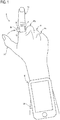
- a wearable camera 2 of the present embodiment is a camera of wearable type, and a user wears it on the index finger F2.
- This wearable camera 2 enables shooting of an object while the user is pointing at the object with one hand, and transmits the shot image to a mobile information terminal M such as a smartphone or a tablet terminal by wireless communication.
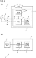
- This wearable camera 2 includes: a camera unit 4 (functional unit 6 ( FIG. 3 )) to transmit the shot image to the mobile information terminal M; and a release switch 8 (switch unit 10 ( FIG. 3 )).
- the wearable camera 2 is configured so that the user wears it on the index finger F2 via a ring-shaped attachment 12.
- the attachment 12 is formed in a size that allows the insertion up to the proximal phalanx of the index finger F2.
- the camera unit 4 is fixed to the attachment 12 so as to be placed above the attachment 12 (on the back of the index finger F2) that is inserted up to the proximal phalanx, and the case of the camera unit 4 is formed so as not to obstruct the movement of the user's fingers as much as possible.
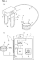
- the case of the camera unit 4 accommodates a circuit board 14 on which electronic components are mounted, and a not-illustrated battery that supplies electric power to the electronic components.
- the electronic components include a not-illustrated power supply circuit that receives electric power from the battery and generates power supply, and a camera module 16, a MCU 18, and a Bluetooth (registered trademark) module 20 that are driven by the power supply.
- the camera module 16 includes an image sensor 22 and a lens 24, and these image sensor 22 and lens 24 are placed close to the front face of the case so as to be placed on the same optical axis.
- the image sensor 22 electrically connects to the MCU 18 and is controlled by the MCU 18. Under the control of the MCU 18, a signal output from each of the elements of the image sensor 22 is input to a not-illustrated A/D converter via an amplifier. The signals output from the A/D converter are input to the MCU 18, and the MCU 18 creates an image based on the signals. The MCU 18 then transmits the created image to the mobile information terminal M via the Bluetooth module 20.
- the image sensor 22, the lens 24, the A/D converter, and the MCU 18 function as an image generator 88 that creates an image
- the MCU 18 and the Bluetooth module 20 function as an image transmitter 90 that transmits an image.
- the mobile information terminal M is a known smartphone or tablet terminal enabling Bluetooth communications and Internet communications, and the user wears this mobile information terminal M on the arm with an attachment 26 such as a band.
- the mobile information terminal M of the present embodiment has an application installed that analyzes one-dimensional symbols, two-dimensional symbols, and characters included in an image received from the wearable camera 2 to acquire the information from them. In this way, the wearable camera 2 and the mobile information terminal M function as a reader that shoots an image and analyzes symbols and characters in the shot image to acquire information.
- the MCU 18 of the camera unit 4 electrically connects to the release switch 8.
- the release switch 8 is of a push button type, and has a keytop 8a exposed so as to let the user push it. To prevent erroneous operation, the keytop 8a of the release switch 8 is preferably exposed flat so as not to protrude.
- One of the terminals 28 of the release switch 8 electrically connects to the power supply of the circuit board 14 via a cable 30a, and the other terminal 32 of the release switch 8 electrically connects to the input of the MCU 18 via a cable 30b. Pushing this release switch 8 with the thumb F1 inputs an ON signal (power-supply level signal) to the MCU 18. Detecting the ON signal, the MCU 18 controls the camera module 16 to start shooting.
- the release switch 8 is fixed to the attachment 12 so as to be placed lateral of the attachment 12 that is inserted up to the proximal phalanx, specifically placed at a position that allows the user to operate it with the thumb F1 (lateral of the index finger F2 to face the thumb F1).
- the release switch 8 is preferably formed to be thin so as not to hinder the movement of the fingers and has a width and a length similar to those of the proximal phalanx.
- the wearable camera 2 of the present embodiment allows the user to wear it on the proximal phalanx of the index finger F2 and operate the release switch 8 with the thumb F1.
- the user therefore operates the release switch 8 with the thumb F1 while pointing the index finger F2 at the object.
- This wearable camera therefore allows a user to shoot an image of an object at a distant position while pointing the index finger at the object and by operating the release switch with the thumb F1.
- the present invention may be embodied as follows.
- the release switch 8 in the above embodiment is of a push button type.
- this may be a switch unit 34 that switches to another state (changes the state) when the thumb F1 comes in contact with the camera unit 4.
- a switch unit 34 includes a ring 38 having a conductive layer 36 (first electrode) on the surface and configured so that the user wears it on the thumb F1, an electrode 40 (second electrode) exposed on a side face of the camera unit 4, and a MCU 18 that detects a contact between the electrode 40 and the ring 38.
- the electrode 40 is exposed on a side face of the case of the camera unit 4 to face the thumb F1.
- the electrode 40 electrically connects to the input of the MCU 18 via a pull-up resister 42.
- the ring 38 that the user wears on the thumb F1 includes a base ring 44 made of an insulator, and conductive rubber 36a bonded to the surface of the base ring 44.
- Core wire of a cable 46 is inserted in a part between the base ring 44 and the conductive rubber 36a.
- the distal end of the cable 46 is connected to the ground of a circuit board 14 in the camera unit 4. This makes the surface of the ring 38 electrically continuous to the ground of the circuit board 14.
- the MCU 18 monitors the input status and detects a change of the status from the power supply level to the ground level as switching. Detecting such switching, the MCU 18 starts shooting control of the camera module 16.
- the user wears the camera unit 4 on the index finger with a pair of strip-shaped bands 92a and 92b. This pair of bands 92a and 92b comes with a pair of hook-and-loop fasteners 94a and 94b so that they can be attached to and detached from each other.
- the above Modified Example 1 is configured so that user's operation of the ring 38 on the thumb F1 to come in contact with the electrode 40 of the camera unit 4 causes the switching. In another example, user's operation to bring the thumb F1 close to the camera unit 4 may cause the switching.
- the switch unit 48 includes a reed switch 50 inside the camera unit 4, a magnet 52 that the user wears on the thumb F1, and the MCU 18 that detects the switching of the reed switch 50.
- the reed switch 50 is placed inside of the camera unit 4 to be close to the thumb F1, and has one terminal connecting to the ground of the circuit board 14 and the other terminal connecting to the input of the MCU 18 via a pull-up resister 42.
- the magnet 52 that the user wears on the thumb F1 is attached to the center of a strip 56 having hook-and-loop fasteners 54a and 54b at both ends. The user wears this strip 56 on the thumb F1 so that the magnet 52 is placed on the pad of the thumb F1.
- the reed switch 50 activates (the contacts come in contact) so that the terminals of the reed switch 50 become electrically continuous to each other.
- a ground level signal is input to the MCU 18.
- the MCU 18 monitors the input status and detects a change of the status from the power supply level to the ground level as switching.
- the magnet 52 functions as an actuator to activate the reed switch 50
- the reed switch 50 functions as an action unit activated by the magnet 52.
- the above embodiment and modified examples are configured so that user's operation of the thumb F1 toward the index finger F2 causes the switching of the switch unit 10, 34, 48.
- user's operation of the thumb F1 toward another finger different from the index finger F2 may cause the switching.
- FIG. 6 may include an independent reed switch unit 58 having a case 58a accommodating the reed switch 50 only, and the user may wear this reed switch unit 58 on the proximal phalanx of the middle finger F3 via a pair of bands 60a and 60b.
- the terminals of this reed switch 50 connect to the ground of the circuit board 14 and the input of the MCU 18 in the camera unit 4 via a cable 62.
- the reed switch 50 activates (the contacts come in contact) so that the terminals of the reed switch 50 become electrically continuous to each other.
- the magnet 52 put on the thumb F1 functions as an actuator to activate the reed switch 50 placed on the middle finger F3
- the reed switch 50 placed on the middle finger F3 functions as an action unit activated by the magnet 52.
- a switch unit 64 may include a first ring 66 put on a fingertip part of the thumb F1 and a second ring 68 put on the proximal phalanx of the middle finger F3. These rings 66 and 68 are configured similarly to the ring 38 of Modified Example 1, and conductive rubber of each of the rings 66 and 68 electrically connects to the circuit board 14 via a cable 70. In one example, the conductive rubber of the first ring 66 connects to the input of the MCU 18 via a pull-up resister, and the conductive rubber of the second ring connects to the ground of the circuit board 14.
- a ground level signal is input to the MCU 18.
- the MCU 18 monitors the input status and detects a change of the status from the power supply level to the ground level as switching.
- the conductive rubber of the first ring 66 functions as the first electrode that gives a ground level signal to the conductive rubber of the second ring 68
- the conductive rubber of the second ring 68 functions as the second electrode.
- the finger to put the second ring 68 thereon may be the ring finger F4 or the little finger F5.
- a switch unit 74 may include a middle-finger switch unit put on the middle finger F3, and an index-finger switch unit put on the index finger F2.
- the index-finger switch unit includes a light source 76 and a phototransistor 78 assembled in the case of the camera unit 4, and the middle-finger switch unit is a ring 80 whose surface is covered with a reflective sheet.
- the light source 76 is typically a LED that irradiates infrared rays at a wide angle.
- the phototransistor 78 receives infrared rays reflected by the ring 80 (reflective sheet), and has the output terminal electrically connecting to the input of the MCU 18.
- Such light source 76 and phototransistor 78 are assembled in the case so that the irradiation surface and the light receiving surface are exposed on the side face of the case facing the middle finger.
- the ring 80 (reflective sheet) is away from the light source 76 and the phototransistor 78, so that the phototransistor 78 does not receive the infrared rays, which would otherwise are reflected by the ring 80 to be incident on the light receiving surface, so that the output level of the phototransistor 78 changes.
- the MCU 18 detects the change of the output level as switching. When the switching is detected, the MCU 18 starts shooting control of the camera module 16.
- a rotary switch may be used, which rotates with the bending motion of the middle finger F3 relative to the index finger F2 and has the output terminal electrically connecting to the input of the MCU 18.
- the MCU 18 detects switching based on a signal change from the rotary switch to control the camera module 16.
- the above embodiment and modified examples are configured so that the output of the switch unit is input to the MCU 18 of the camera unit 4 via a cable or the like.
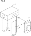
- another example may be configured so that a switch unit 82 and a camera unit 4 are connected with a connector.
- the case of the camera unit 4 has a female connector 84 on the side face facing the thumb.
- the switch unit 82 comes with a male connector 86 on the inside, and the male connector 86 is detachable from the female connector 84.
- the female connector 84 has at least two terminals. One of the terminals electrically connects to the input of the MCU 18 in the camera unit 4, and the other terminal electrically connects to the power supply of the circuit board 14.
- the male connector 86 has connectors as the counterparts. The terminals of the male connector 86 electrically connect to the terminals of the release switch 8.
- the camera unit 4 may include the female connectors 84 on opposed faces of the case (to face the thumb and the middle finger). Such connectors on the opposed faces of the case enables selection of the position where the user wears the switch unit 82, whereby the user may wear the wearable camera either on the right hand or on the left hand for use.
- Embodiments of the present invention can be variously improved, altered, or modified based on the knowledge of those skilled in the art without departing from the spirit of the present invention. Any matters specifying the invention may be replaced with other techniques in an embodiment as long as the same action or effects are obtained from the embodiment.
- the wearable camera as an example of the wearable device.
- the wearable device may be a pointing device that irradiates a red laser beam in response to the switching of the switch unit.
Landscapes
- Engineering & Computer Science (AREA)
- Theoretical Computer Science (AREA)
- General Engineering & Computer Science (AREA)
- Physics & Mathematics (AREA)
- Multimedia (AREA)
- Signal Processing (AREA)
- General Physics & Mathematics (AREA)
- Human Computer Interaction (AREA)
- Electromagnetism (AREA)
- Health & Medical Sciences (AREA)
- General Health & Medical Sciences (AREA)
- Toxicology (AREA)
- Artificial Intelligence (AREA)
- Computer Vision & Pattern Recognition (AREA)
- User Interface Of Digital Computer (AREA)
- Studio Devices (AREA)
Applications Claiming Priority (2)
| Application Number | Priority Date | Filing Date | Title |
|---|---|---|---|
| JP2018162215 | 2018-08-30 | ||
| PCT/JP2019/034076 WO2020045616A1 (fr) | 2018-08-30 | 2019-08-30 | Dispositif pouvant être porté |
Publications (2)
| Publication Number | Publication Date |
|---|---|
| EP3846006A1 true EP3846006A1 (fr) | 2021-07-07 |
| EP3846006A4 EP3846006A4 (fr) | 2022-05-25 |
Family
ID=69643655
Family Applications (1)
| Application Number | Title | Priority Date | Filing Date |
|---|---|---|---|
| EP19854998.2A Pending EP3846006A4 (fr) | 2018-08-30 | 2019-08-30 | Dispositif pouvant être porté |
Country Status (4)
| Country | Link |
|---|---|
| US (1) | US20210240263A1 (fr) |
| EP (1) | EP3846006A4 (fr) |
| JP (1) | JPWO2020045616A1 (fr) |
| WO (1) | WO2020045616A1 (fr) |
Families Citing this family (2)
| Publication number | Priority date | Publication date | Assignee | Title |
|---|---|---|---|---|
| US12248842B2 (en) * | 2022-12-09 | 2025-03-11 | Rgis International Holdings, Llc | Ring scanner with counting function and method thereof |
| KR102868319B1 (ko) * | 2023-09-13 | 2025-10-02 | 장상훈 | 의료용 드릴 |
Family Cites Families (20)
| Publication number | Priority date | Publication date | Assignee | Title |
|---|---|---|---|---|
| JPS6140074U (ja) * | 1984-08-18 | 1986-03-13 | キヤノン株式会社 | 電子機器 |
| US6003774A (en) * | 1991-11-04 | 1999-12-21 | Symbol Technologies, Inc. | Portable optical scanning and pointing systems |
| JP3243788B2 (ja) * | 1997-01-07 | 2002-01-07 | 日本電信電話株式会社 | 単一センサ型常装着入力装置 |
| US6764012B2 (en) * | 1997-02-10 | 2004-07-20 | Symbol Technologies, Inc. | Signaling arrangement for and method of signaling in a wireless local area network |
| JP2002196790A (ja) * | 2000-12-25 | 2002-07-12 | Media Consultant:Kk | 音声認識用データ送信装置及び音声認識システム |
| JP2002261901A (ja) * | 2000-12-26 | 2002-09-13 | Seiko Instruments Inc | 腕携帯情報機器 |
| JP2004192167A (ja) * | 2002-12-09 | 2004-07-08 | Matsushita Electric Ind Co Ltd | 携帯端末及び情報入力装置 |
| US7871006B2 (en) * | 2006-09-29 | 2011-01-18 | Symbol Technologies, Inc. | Trigger unit for a wearable data acquisition device |
| AU2008290211A1 (en) * | 2007-08-19 | 2009-02-26 | Ringbow Ltd. | Finger-worn devices and related methods of use |
| US20120139708A1 (en) * | 2010-12-06 | 2012-06-07 | Massachusetts Institute Of Technology | Wireless Hand Gesture Capture |
| US8371506B2 (en) * | 2011-01-26 | 2013-02-12 | Koamtac, Inc. | Handheld barcode code input device with no-power supplied switch trigger |
| US10139906B1 (en) * | 2014-01-29 | 2018-11-27 | Guiyu Bai | Ring human-machine interface |
| US9344537B2 (en) * | 2014-02-20 | 2016-05-17 | Naseem Karimbaksh KHAN | Glove with user-interactable electronic components |
| JP5695806B1 (ja) | 2014-02-20 | 2015-04-08 | 株式会社ウェルキャット | コード読取装置 |
| US9224027B2 (en) * | 2014-04-01 | 2015-12-29 | Hand Held Products, Inc. | Hand-mounted indicia-reading device with finger motion triggering |
| JP2016139342A (ja) * | 2015-01-28 | 2016-08-04 | キヤノン株式会社 | 装置連携による情報入力方法、情報処理装置、コンピュータプログラム |
| EP3075312B1 (fr) * | 2015-03-31 | 2020-07-29 | Nokia Technologies Oy | Appareils pour mesurer la résistance de la peau |
| JP6696384B2 (ja) * | 2016-09-28 | 2020-05-20 | 株式会社デンソー | 検査装置 |
| JP2018073232A (ja) * | 2016-11-01 | 2018-05-10 | シャープ株式会社 | 情報処理装置、コード読取方法、及びプログラム |
| TWM547134U (zh) * | 2017-02-03 | 2017-08-11 | Marson Technology Co Ltd | 指環型條碼掃描器 |
-
2019
- 2019-08-30 JP JP2020539616A patent/JPWO2020045616A1/ja active Pending
- 2019-08-30 EP EP19854998.2A patent/EP3846006A4/fr active Pending
- 2019-08-30 WO PCT/JP2019/034076 patent/WO2020045616A1/fr not_active Ceased
- 2019-08-30 US US17/270,171 patent/US20210240263A1/en not_active Abandoned
Also Published As
| Publication number | Publication date |
|---|---|
| US20210240263A1 (en) | 2021-08-05 |
| EP3846006A4 (fr) | 2022-05-25 |
| WO2020045616A1 (fr) | 2020-03-05 |
| JPWO2020045616A1 (ja) | 2021-08-26 |
Similar Documents
| Publication | Publication Date | Title |
|---|---|---|
| EP3637300B1 (fr) | Dispositif de lecture d'indice monté manuellement avec déclenchement par mouvement tactile | |
| EP3091423B1 (fr) | Module d'indication de position et stylet | |
| CN105556433B (zh) | 用于电子设备的触觉开关 | |
| EP3644217A1 (fr) | Dispositif électronique portable | |
| EP3168852B1 (fr) | Ensemble de commutateur et dispositif portatif | |
| EP1836945A2 (fr) | Mécanisme à commutation à utiliser dans des appareils médicaux, et dispositif de capture d'images à utiliser dans des endoscopes | |
| EP3846006A1 (fr) | Dispositif pouvant être porté | |
| EP1570547A1 (fr) | Systeme de contacts de connecteur a cycle eleve | |
| EP4585379A3 (fr) | Appareil de soins personnels | |
| JP7155899B2 (ja) | ウェアラブル電子装置 | |
| CN110502945B (zh) | 穿戴式扫描器 | |
| WO2008070634A1 (fr) | Scanner à bague multimode | |
| CN110943349A (zh) | 数据连接器、电子设备、数据连接线和数据连接传输系统 | |
| CN217135561U (zh) | 保护框及摄像装置 | |
| CN105069392B (zh) | 一种扫码装置 | |
| EP3651054B1 (fr) | Système de lecture et caméra | |
| KR101650659B1 (ko) | 탄력 직진성이 우수한 고해상도 스마트폰용 내시경 | |
| CN108304065B (zh) | 具有红外识别手势功能的智能腕带和红外检测传感器组件 | |
| JP7192956B2 (ja) | 電子機器 | |
| US20190051470A1 (en) | Compressible housing | |
| CN210402353U (zh) | 穿戴式扫描器 | |
| CN110493399B (zh) | 一种发光装置 | |
| KR102372040B1 (ko) | 인간형 로봇 완구 조종 장치 | |
| CN101728625B (zh) | 天线模块 | |
| JP7139770B2 (ja) | 情報読取装置 |
Legal Events
| Date | Code | Title | Description |
|---|---|---|---|
| STAA | Information on the status of an ep patent application or granted ep patent |
Free format text: STATUS: THE INTERNATIONAL PUBLICATION HAS BEEN MADE |
|
| STAA | Information on the status of an ep patent application or granted ep patent |
Free format text: STATUS: REQUEST FOR EXAMINATION WAS MADE |
|
| PUAI | Public reference made under article 153(3) epc to a published international application that has entered the european phase |
Free format text: ORIGINAL CODE: 0009012 |
|
| 17P | Request for examination filed |
Effective date: 20210305 |
|
| AK | Designated contracting states |
Kind code of ref document: A1 Designated state(s): AL AT BE BG CH CY CZ DE DK EE ES FI FR GB GR HR HU IE IS IT LI LT LU LV MC MK MT NL NO PL PT RO RS SE SI SK SM TR |
|
| DAV | Request for validation of the european patent (deleted) | ||
| DAX | Request for extension of the european patent (deleted) | ||
| A4 | Supplementary search report drawn up and despatched |
Effective date: 20220428 |
|
| RIC1 | Information provided on ipc code assigned before grant |
Ipc: G06K 7/10 20060101ALN20220421BHEP Ipc: G06F 3/02 20060101ALI20220421BHEP Ipc: H04N 5/232 20060101ALI20220421BHEP Ipc: H04N 5/225 20060101ALI20220421BHEP Ipc: G06F 3/01 20060101AFI20220421BHEP |
|
| STAA | Information on the status of an ep patent application or granted ep patent |
Free format text: STATUS: EXAMINATION IS IN PROGRESS |
|
| 17Q | First examination report despatched |
Effective date: 20240220 |