EP3846192A1 - Boîte de soufflage pour dispositifs de protection de circuit - Google Patents
Boîte de soufflage pour dispositifs de protection de circuit Download PDFInfo
- Publication number
- EP3846192A1 EP3846192A1 EP20212947.4A EP20212947A EP3846192A1 EP 3846192 A1 EP3846192 A1 EP 3846192A1 EP 20212947 A EP20212947 A EP 20212947A EP 3846192 A1 EP3846192 A1 EP 3846192A1
- Authority
- EP
- European Patent Office
- Prior art keywords
- arc chute
- magnet
- arc
- insulator
- side walls
- Prior art date
- Legal status (The legal status is an assumption and is not a legal conclusion. Google has not performed a legal analysis and makes no representation as to the accuracy of the status listed.)
- Granted
Links
Images





Classifications
-
- H—ELECTRICITY
- H01—ELECTRIC ELEMENTS
- H01H—ELECTRIC SWITCHES; RELAYS; SELECTORS; EMERGENCY PROTECTIVE DEVICES
- H01H33/00—High-tension or heavy-current switches with arc-extinguishing or arc-preventing means
- H01H33/02—Details
- H01H33/04—Means for extinguishing or preventing arc between current-carrying parts
- H01H33/08—Stationary parts for restricting or subdividing the arc, e.g. barrier plate
-
- H—ELECTRICITY
- H01—ELECTRIC ELEMENTS
- H01H—ELECTRIC SWITCHES; RELAYS; SELECTORS; EMERGENCY PROTECTIVE DEVICES
- H01H9/00—Details of switching devices, not covered by groups H01H1/00 - H01H7/00
- H01H9/30—Means for extinguishing or preventing arc between current-carrying parts
- H01H9/34—Stationary parts for restricting or subdividing the arc, e.g. barrier plate
- H01H9/36—Metal parts
-
- H—ELECTRICITY
- H01—ELECTRIC ELEMENTS
- H01H—ELECTRIC SWITCHES; RELAYS; SELECTORS; EMERGENCY PROTECTIVE DEVICES
- H01H9/00—Details of switching devices, not covered by groups H01H1/00 - H01H7/00
- H01H9/30—Means for extinguishing or preventing arc between current-carrying parts
- H01H9/44—Means for extinguishing or preventing arc between current-carrying parts using blow-out magnet
-
- H—ELECTRICITY
- H01—ELECTRIC ELEMENTS
- H01H—ELECTRIC SWITCHES; RELAYS; SELECTORS; EMERGENCY PROTECTIVE DEVICES
- H01H33/00—High-tension or heavy-current switches with arc-extinguishing or arc-preventing means
- H01H33/02—Details
- H01H33/53—Cases; Reservoirs, tanks, piping or valves, for arc-extinguishing fluid; Accessories therefor, e.g. safety arrangements, pressure relief devices
-
- H—ELECTRICITY
- H01—ELECTRIC ELEMENTS
- H01H—ELECTRIC SWITCHES; RELAYS; SELECTORS; EMERGENCY PROTECTIVE DEVICES
- H01H33/00—High-tension or heavy-current switches with arc-extinguishing or arc-preventing means
- H01H33/70—Switches with separate means for directing, obtaining, or increasing flow of arc-extinguishing fluid
- H01H33/7015—Switches with separate means for directing, obtaining, or increasing flow of arc-extinguishing fluid characterised by flow directing elements associated with contacts
-
- H—ELECTRICITY
- H01—ELECTRIC ELEMENTS
- H01H—ELECTRIC SWITCHES; RELAYS; SELECTORS; EMERGENCY PROTECTIVE DEVICES
- H01H73/00—Protective overload circuit-breaking switches in which excess current opens the contacts by automatic release of mechanical energy stored by previous operation of a hand reset mechanism
- H01H73/02—Details
- H01H73/18—Means for extinguishing or suppressing arc
-
- H—ELECTRICITY
- H01—ELECTRIC ELEMENTS
- H01H—ELECTRIC SWITCHES; RELAYS; SELECTORS; EMERGENCY PROTECTIVE DEVICES
- H01H9/00—Details of switching devices, not covered by groups H01H1/00 - H01H7/00
- H01H9/30—Means for extinguishing or preventing arc between current-carrying parts
- H01H9/44—Means for extinguishing or preventing arc between current-carrying parts using blow-out magnet
- H01H9/443—Means for extinguishing or preventing arc between current-carrying parts using blow-out magnet using permanent magnets
-
- H—ELECTRICITY
- H01—ELECTRIC ELEMENTS
- H01H—ELECTRIC SWITCHES; RELAYS; SELECTORS; EMERGENCY PROTECTIVE DEVICES
- H01H9/00—Details of switching devices, not covered by groups H01H1/00 - H01H7/00
- H01H9/30—Means for extinguishing or preventing arc between current-carrying parts
- H01H9/34—Stationary parts for restricting or subdividing the arc, e.g. barrier plate
- H01H9/36—Metal parts
- H01H2009/365—Metal parts using U-shaped plates
-
- H—ELECTRICITY
- H01—ELECTRIC ELEMENTS
- H01H—ELECTRIC SWITCHES; RELAYS; SELECTORS; EMERGENCY PROTECTIVE DEVICES
- H01H33/00—High-tension or heavy-current switches with arc-extinguishing or arc-preventing means
- H01H33/02—Details
- H01H33/59—Circuit arrangements not adapted to a particular application of the switch and not otherwise provided for, e.g. for ensuring operation of the switch at a predetermined point in the AC cycle
- H01H33/596—Circuit arrangements not adapted to a particular application of the switch and not otherwise provided for, e.g. for ensuring operation of the switch at a predetermined point in the AC cycle for interrupting DC
-
- H—ELECTRICITY
- H01—ELECTRIC ELEMENTS
- H01H—ELECTRIC SWITCHES; RELAYS; SELECTORS; EMERGENCY PROTECTIVE DEVICES
- H01H71/00—Details of the protective switches or relays covered by groups H01H73/00 - H01H83/00
- H01H71/02—Housings; Casings; Bases; Mountings
- H01H71/0207—Mounting or assembling the different parts of the circuit breaker
- H01H71/0235—Contacts and the arc extinguishing space inside individual separate cases, which are positioned inside the housing of the circuit breaker
-
- H—ELECTRICITY
- H01—ELECTRIC ELEMENTS
- H01H—ELECTRIC SWITCHES; RELAYS; SELECTORS; EMERGENCY PROTECTIVE DEVICES
- H01H9/00—Details of switching devices, not covered by groups H01H1/00 - H01H7/00
- H01H9/30—Means for extinguishing or preventing arc between current-carrying parts
- H01H9/302—Means for extinguishing or preventing arc between current-carrying parts wherein arc-extinguishing gas is evolved from stationary parts
-
- H—ELECTRICITY
- H01—ELECTRIC ELEMENTS
- H01H—ELECTRIC SWITCHES; RELAYS; SELECTORS; EMERGENCY PROTECTIVE DEVICES
- H01H9/00—Details of switching devices, not covered by groups H01H1/00 - H01H7/00
- H01H9/30—Means for extinguishing or preventing arc between current-carrying parts
- H01H9/34—Stationary parts for restricting or subdividing the arc, e.g. barrier plate
- H01H9/345—Mounting of arc chutes
Definitions
- the present disclosure relates an arc chute for circuit protective devices, and more particularly, to an arc chute with one or more permanent magnets to direct arcing toward a side wall of the arc chamber.
- Circuit breakers are used to interrupt current flow in the event of abnormal operating conditions, such as a short circuit or current overload.
- electrical contacts are separated. Electrical arcing may occur between the contacts as they are separated, resulting in potential damage to the contacts as well as other components in the circuit breaker from electrical and heat energy generated from arcs or arcing. The quick extinction of this arc is desired not only to minimize damage to the circuit breaker but to interrupt the current as quickly as possible to protect the wires and load.
- AC circuits are generally used in many of today's power systems however, DC circuits are becoming more popular due to the use of batteries, DC converters, LED lighting, DC motors, and photovoltaic arrays all of which are inherently DC powered.
- an apparatus for extinguishing an arc.
- the apparatus can include an arc chute that can include a pair of opposing side walls, a non-magnetic body arranged between the side walls, and a back wall arranged on a back side of the non-magnetic body.
- the side walls are formed of an electrically insulating material.
- the non-magnetic body has an open area and a plurality of slots through which to facilitate gas flow.
- the back wall includes at least one first insulator and at least one magnet.
- the at least one first insulator is arranged between the at least one magnet and the open area and configured to electrically isolate the magnet from the non-magnetic body.
- the magnet can generate a magnetic field to redirect an arc in the open area toward one of the side walls, depending on current direction.
- the side-walls can be formed by inserting the arc chute inside of the arc chamber or there may be side walls created from an insulating material which can also be used to support the metal arc plate stack.
- the non-magnetic body can be a non-ferromagnetic body, which comprises a plurality of stacked metal plates that are spaced-apart to form the plurality of slots therebetween.
- Each plate of the plurality of stacked metal plates can have a pair of arms extending from a base which is connected therebetween. The open area is formed between the pair of arms of the stacked metal plates.
- Each plate of the plurality of stacked metal plates can have a U-shaped profile or a ⁇ -shaped profile.
- the at least one first insulator can include a plurality of spaced apart grooves or recesses configured to engage and support an outer surface of the base of corresponding plates from the plurality of stacked metal plates, and is configured to support the at least one magnet.
- the at least one first insulator can also include one or more vent openings through which to facilitate gas flow out from the open area.
- the at least one magnet can have a first end and an opposite second end. The first and second ends can each have an opposite magnetic polarity with one of the first or second end facing toward the open area across the at least one first insulator.
- the at least one first insulator can also include at least one pocket for supporting the at least one magnet.
- the at least one first insulator can further include one or more vent openings through which to facilitate gas flow out from the open area, the at least one magnet comprises a plurality of magnets, and the at least one first insulator includes a plurality of pockets for supporting the plurality of magnets at different locations. The plurality of pockets can be separated by the one or more vent openings.
- the apparatus can further include a pair of second insulators each including a plurality of spaced apart grooves or recesses configured to engage and support corresponding plates from the plurality of stacked metal plates.
- Each second insulator can be engaged to the plurality of plates of a respective one of the pair the side walls.
- each of the pair of second insulators can be configured to engage an open end of a corresponding arm of the pair of arms.
- the arc chute can also include at least one side gas channel.
- the first and/or second insulators can comprise of nylon.
- a circuit protective device which includes a first electrical contact, and a movable second electrical contact, which when engaged with the first electrical contact, is configured to enable current flow thereacross to a circuit.
- the circuit protective device can further include the apparatus for extinguishing an arc or an arc chute, such as described herein.
- the circuit protective device can include a case for housing the first and second electrical contacts and the arc chute.
- the side walls of the arc chute of the apparatus can be formed as part of the case or side walls of an arc chamber in the case.
- the circuit protective device can be a bi-directional DC circuit breaker or still function as an AC circuit breaker.
- the present disclosure relates to an arc chute for a circuit protective device, such as a circuit breaker.
- the arc chute includes a pair of opposing side walls, a back wall and a non-magnetic body for extinguishing an arc.
- the non-magnetic body is arranged between the side walls and back wall, and includes an open area (or space), also referred to as an arc quenching chamber.
- the back wall e.g., toward a vent side
- the one or more magnets on the back wall can generate a magnet field to redirect arcing in or around the open area toward one of the side walls of the arc chute, such as for example due to disengagement of electrical contacts of the circuit protective device,.
- the non-magnetic body can include a stack of non-magnetic metal plates (e.g., non-ferromagnetic plates, etc.), which are spaced-apart to provide a plurality of slots through which to facilitate the flow of gas (or gas flow), such as produced as a result of arcing, out from the open area of the non-magnetic body between the opposing side walls.
- the arc chute can also be designed with gas channels on an outer side surface and/or outer back surface of the non-magnetic body to control or facilitate movement of gas flow to one or more vents or venting components of the circuit protective device.
- Such an arc chute configuration with the magnet(s) arranged at a back (or vent-side) of the arc chute can break-up arcs quickly and effectively through the use of magnetic fields to redirect an arc(s) to one of the side walls, where the slotted design can also help to extinguish arcs.
- Such an arc chute configuration is more versatile than an arc chute that employs magnets on the sides of the chute to redirect arcing towards a back of the chute.
- An arc chute with magnets on the sides can be used primarily with unidirectional circuit breakers, e.g., where current flow is in one direction (or polarity) through a circuit protective device.
- the arc chute configuration of the present disclosure can be used with bi-directional circuit breakers in which the terminals are interchangeable, e.g., first and second terminals are connectable to the load and line wiring respectively, or vice-a-versa.
- the magnet(s) By positioning the magnet(s) at the back of the arc chute, arcs in a bi-directional circuit breaker can be redirected to one or the other of the side walls of the arc chute according to the direction (or polarity) of current flow through the circuit breaker.
- the arc chute configuration of the present disclosure can also incorporate gas channels to direct or facilitate movement of gases to the vent(s) of the circuit breaker or arc chamber which includes the arc chute, the vent and electrical contact assembly.
- the arc chute configuration can also incorporate one or more insulators to support the non-magnetic body or portions thereof (e.g., a stack of non-magnetic or deionizing plates), and insulator materials such as nylon or other materials which can produce gases as a result of arcing to further help extinguish an arc(s) and to cool down the arc chute.
- the magnetic field created by the permanent magnet also serves to cool the arc by increasing convective losses due to the increased turbulence produced by the magnetic field produced by the permanent magnet. The faster the arc can be cooled, the quicker and more efficient the arc extinction process becomes.
- Various arc chute designs or configurations will be described in greater detail below with reference to the figures.
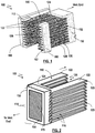
- Figs. 1 and 2 show front and back perspective views of an arc chute 100 in accordance with a first embodiment.
- the arc chute 100 can be employed in a circuit protective device to extinguish an electric arc which may result from operation of the circuit protective device, such as the engagement or disengagement of electrical contacts therein.
- the circuit protective device can be a circuit breaker, such as an AC or DC circuit breaker, a contactor, or other circuit protective device.
- the arc chute 100 includes a non-magnetic body 110 for extinguishing an arc, a pair of opposing side walls 112, and a back wall 114.
- the non-magnetic body 110 includes a plurality of slots 116 for facilitating gas flow, and an open area (or space) 126.
- the non-magnetic body 110 is arranged between the side walls 112.
- the side walls 112 can be formed of an electrically insulating material, such as a non-magnetic or other insulating material (e.g., fiberboard or glass polyester).
- the back wall (or vent end) 114 includes a back insulator 150 to support at least one magnet 170 (e.g., a permanent magnet), and to electrically isolate the magnet 170 from the non-magnetic body 110.
- the magnet 170 can be retained in a pocket 154 (e.g., pocket, recess or recessed area, etc.) of the back insulator 150.
- the magnet 170 which is arranged at the back of the arc chute 100, is configured to generate a magnet field(s) to redirect arcs generated in or around the open area 126 toward one of the side walls 112 (or one of the sides of the non-magnetic body 110).
- the non-magnetic body 110 can be formed of a plurality of stacked plates 120 (e.g., deionizing plates) which are spaced-apart from each other to form the plurality of slots 116 (e.g., slots, openings, through-holes, etc.).
- each of the plates 120 of the body 110 can include a base 124 and a pair of opposing arms 122 which extend from the base 124.
- the open area 126 is formed or provided between the pair of opposing arms 122 of the stacked plates 120.
- the non-magnetic body 110 and its plates 120 can have a U-shape profile.
- the plates 120 can be made of a non-magnetic material such as non-ferromagnetic material, non-magnetic steel (e.g., 304 or 316 stainless steel) or other non-magnetic metals (e.g., copper, brass, etc.), and can be formed by stamping, molding or other manufacturing techniques to obtain a desired shape.
- a non-magnetic material such as non-ferromagnetic material, non-magnetic steel (e.g., 304 or 316 stainless steel) or other non-magnetic metals (e.g., copper, brass, etc.), and can be formed by stamping, molding or other manufacturing techniques to obtain a desired shape.
- the arc chute 100 can utilize the back insulator 150 and front (or side) insulators 160 to support the plates 120 of the body 110.
- the back insulator 150 and front insulators 160 can include a plurality of spaced-apart grooves or recesses (e.g., blind slots, etc.) 152 and 162 respectively, which are configured with a size and shape to engage and support corresponding plates from the plurality of stacked plates 120.
- Each front insulator 160 can be positioned (or arranged) on an outer side surface or portion at or around an open end of each of the pair of side walls 112.
- the insulators 150 and 160 can be formed of an electrically insulating material to electrically isolate the magnet 170 from the non-magnetic body 110 and its component(s).
- the insulators 150 and 160 can also be formed of a suitable material (e.g., nylon, nylon composite, etc.) which can produce gases as a result of arcing to help extinguish an arc and to cool down the arc chute.
- the back insulator 150 can include at least one pocket 154 for supporting and retaining the magnet 170.
- the insulators 150, 160 can include vent openings to facilitate the flow of gases out from the open area 126.
- the back insulator 150 can partially surround the magnet 170 as shown, or alternatively fully surround the magnet 170.
- the side walls 112 can be arranged relative to a respective outer side of the non-magnetic body 110.
- the proximity of each side wall 112 to a respective side of the body 110 as well as its dimension, shape or size can be configured according to the arc chute design, such as whether a front/side insulator 160 is to be utilized, whether side gas channels are incorporated, the size and shape of the plates of the body 110, the configuration of an arc chamber including its housing, and so forth.
- the side walls 112 can be formed by inserting the arc chute inside of the arc chamber (e.g., side-walls of the arc chamber become the side-walls of the arc chute) or side walls can be created from an insulating material which can also be used to support the stack of plates.
- the magnet 170 can generate a magnet field(s), as generally indicated by the example field lines, around the arc chute 100 and across the open area 126.
- one magnetic pole e.g., North (N) or South (S)
- a moving arm 550 of a contact assembly of a circuit protective device can include or carry a moving electrical contact 552 (on an underside generally identified by broken lines).
- the moving arm 550 can pass through the open area 126 to engage or disengage from another electrical contact 560 (e.g., a stationary contact) of a contact assembly of the circuit protective device to enable or interrupt current flow, respectively.
- the electrical contact 560 can be arranged below (e.g., immediately below) the arc chute 100.
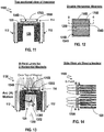
- Fig. 7 is a top-sectional view of a portion of an arc chute 700 in accordance with a second embodiment.
- the arc chute 700 can include the same or similar components as the arc chute 100 of Fig. 1 , except that a back insulator 150A can include at least one vertical vent opening 750 (e.g., opening, slot, through-hole, etc.) and can support a plurality of vertical magnets 170A in respective pockets 154A as shown in Figs. 7 and 8 .
- the vertical vent opening(s) 750 can facilitate the flow of gases out from the open area 126.
- the arc chute 700 can also include additional front/side insulators (e.g., 160 in Fig. 1 or others described herein) arranged on an outer surface of the side walls 112.
- the magnets 170A can generate magnet fields, as shown by the example field lines, around the arc chute 700 and across the open area 126.
- a moving arm 950 of a circuit protective device can include or carry a moving electrical contact 952 (on an underside generally identified by broken lines).
- the moving arm 950 can pass through the open area 126 to engage or disengage the moving electrical contact 952 to or from another electrical contact 960 (e.g., a stationary contact), respectively, of the circuit protective device to enable or interrupt current flow, respectively.
- another electrical contact 960 e.g., a stationary contact
- Fig. 11 is a top-sectional view of a portion of an arc chute 1100 in accordance with a third embodiment.
- the arc chute 1100 can include the same or similar components as the arc chute 100 of Fig. 1 , except that a back insulator 150B can include at least one horizontal vent opening 1250 and can support a plurality of horizontal magnets 170B in respective pockets 154B as shown in Figs. 11 and 12 .
- the horizontal vent opening(s) 1250 (e.g., in Fig. 12 ) can facilitate the flow of gases out from the open area 126.
- the arc chute 1100 can also include additional front/side insulators (e.g., 160 in Fig. 1 or others described herein) arranged on an outer surface of the side walls 112.
- the magnets 170B can generate a magnet field(s), as shown by the example field lines, around the arc chute 1100 and across the open area 126.
- a moving arm 1350 of a circuit protective device can include or carry a moving electrical contact 1352 (on an underside generally identified by broken lines). The moving arm 1350 can pass through the open area 126 to engage or disengage the moving electrical contact 1352 to and from another electrical contact 1360 (e.g., a stationary contact), respectively, of the circuit protective device to enable or interrupt current flow, respectively.
- the resulting arc(s) can be redirected by the magnetic fields generated by the magnet 170B toward one of the pair of side walls 112 to extinguish the arc(s).
- the back insulator can be formed as a single piece or multiple pieces, and can be configured with vent openings and magnets at desired positions on or along a back wall of the arc chute.
- the back insulator can have vertical and/or horizontal vent openings and/or openings having other dimensions, shape or sizes.
- the vent openings for the back and other insulators can be arranged (or positioned) to correspond with the slots on the non-magnet body (e.g., 110) or components of the arc chute.
- Other example insulator configurations, such as for the front/side insulators, will be described below with reference to the examples Figs. 16-20 .
- the side walls (or portions thereof) of the arc chute may be arranged against or in proximity to an outer side of the non-magnetic body according to the arc chute design.
- Figs. 15 and 16A illustrate front and top views, respectively, of some of the components of an arc chute 1500 in accordance with a fourth embodiment.
- the arc chute 1500 can include the same or similar components as the arc chute 100 of Fig. 1 , except that a front insulator 160C can be arranged across a face (or front) of an open end of each side wall 112.
- the body 110 includes a plurality of spaced-apart stacked plates 120, which are received and held within the grooves or recesses 162 of the insulators 160C.
- the width of the front insulator 160C can correspond to a width of a respective arm 122C of the body 120 (e.g., a width of a face of an open end of the arm 122C).
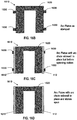
- Figs. 16B through 16D illustrate an example process for forming some of the components of an arc chute, such as the non-magnetic body and side walls, in accordance with various embodiments.
- each plate 1620 of a non-magnetic body 1610 can be formed with a plurality of stakes 1630 on an outer side portion of the plate.
- plates 1620 can then be staked to the side walls via the stakes 1630.
- the protruding portions of the stakes 1630 can be spun to reduce or remove them from the arc chute assembly.
- the back insulator and magnet(s) can be incorporated into the assembly, which can then be inserted into a case/housing of a circuit protective device (e.g., circuit breaker, contactor, etc.) to create an area generally referred to as the arc chamber.
- a circuit protective device e.g., circuit breaker, contactor, etc.
- the arc chamber can include arc chute, venting, and contact assembly. The process described above is simply provided as an example for forming an arc chute in accordance with one or more embodiments such as described herein.
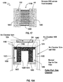
- Figs. 17 and 18A illustrate front and top views, respectively, of some of the components of an arc chute 1700, in accordance with a fifth embodiment.
- the arc chute 1700 can include the same or similar components as the arc chute 100 of Fig. 1 , except that each front insulator 160D can be arranged across a face (or front) of an open end of a respective arm 122D of a non-magnetic body 110D, and the arc chute 1700 can be designed with side gas channels 1850 (e.g., a vertical recessed area or gap).
- the body 110D includes a plurality of spaced-apart stacked plates 120D, which are received and held within the grooves or recesses 162 of the insulators 160D.
- Extending portions (or moldings) 1814 of the base 124D of the body 110D can extend beyond an outer side of the arms 122D, and the front insulators 160D can also extend beyond a face (or front) of an open end of each of the arms 122D.
- the extending portions 1814 of the base 124D and the front insulators 160D together with an outer surface of the side walls 112D can form gas channels 1850 for directing gas flow, such as for example toward a vent or venting components of a circuit protective device.
- the gas channels are formed by a combination of portions of the non-magnetic body 110D and the front insulators 160D along with the side walls 112D.
- the body 110D can have a ⁇ -shaped profile.
- the assembly of the arc chute 1700 can be inserted into an arc chamber 1800 of a circuit protective device.
- gases produced as a result of arcing can be directed toward an arc chamber vent 1854 at a vent end (or back) of the arc chamber 1800.
- some of the gases may be channeled from the side channels 1850 through slots at the base of the body 110 to the vent 1854.
- the circulation of the gases can help to further extinguish arc by cooling the arc.
- Fig. 18B illustrates an arc chute 1700A, which is an alternative example arc chute configuration to the arc chute 1700 in Fig. 18A .
- side walls of the arc chute can be formed using side walls 1852 of the arc chamber 1800.
- Fig. 18C illustrates an arc chute 1700B, which is another alternative example arc chute configuration to the arc chute 1700 in Fig. 18A .
- the non-magnetic body 110DB includes a recessed area on each outer side of the body, which together with the side wall (e.g., 112D) form side channels 1850 for directing gas flow, such as for example toward a vent or venting components of a circuit protective device.
- Figs. 19 and 20 illustrate front and top views, respectively, of some of the components of an arc chute 1900 in accordance with a sixth embodiment.
- the arc chute 1900 can include the same or similar components as the arc chute 100 of Fig. 1 , except that each side insulator 160E can be arranged on a side of a front of an open end of an arm 122E of a non-magnetic body 110E, and the arc chute 1900 can be designed with a side gas channel 2050 (e.g., a vertical recessed area or gap) on its side(s).
- the body 110E includes a plurality of spaced-apart stacked plates 120E, which are received and held within the grooves or recesses 162 of the insulators 160E.
- Extending portions (or moldings) 2014 of the base 114E of the body 110E can extend beyond an outer side of the side walls 112E, and the side insulators 160E can also extend from an outer side of each of the arms 122E of the body 110E.
- the side insulators 160E and the extending portions 2014 of the base 114E together with the side walls 112E can form gas channels 2050 for directing gas flow, such as toward a vent or venting components of a circuit protective device.
- the body 110E can have a ⁇ -shaped profile.
- gas channels can be formed by a combination of portions of the non-magnetic body and the front/side insulators (e.g., Figs. 17-20 ), with a desired shape and direction.
- gas channel(s) can be formed by configuring a shape of the outer surface of the non-magnetic body (e.g., the stacked plates) with one or more vertical or horizontal recesses or gaps or a combination thereof on the outer surface of the walls (e.g., side and/or back walls), and/or through the use of additional insulators spaced-apart along an outer surface of the non-magnetic body.
- the arc chute design can also have tabs designed in as part of the metal plate and then staked or spun down to an insulator piece.
- the grooves (e.g., grooves, recesses, slots, etc.) of the insulators which are configured to receive and support the plates of the non-magnetic body of the arc chute as well as separate and isolate the plates from each other, can be formed by stamping, cutting, molding or other manufacturing techniques.
- the insulators and the non-magnet body can be joined using corresponding male and female parts (e.g., tongue and groove) for joining components, with the male part or the female part on the insulator or the non-magnetic body.
- each plate of the non-magnetic body can be formed as one piece or a plurality of pieces.
- the pair of arms of each plate can be separate pieces, which are connected to the back insulator for support.
- the various components of the arc chute e.g., non-magnetic body, insulator(s), side walls, back wall, etc.
- the arc chute as described herein can be used with different types of circuit protective devices, including but not limited to a molded case circuit breaker (MCCB), miniature circuit breaker (MCB), unidirectional or bi-directional circuit breaker, circuit breaker with a single or double-arm moving assembly, and so forth.
- the circuit breaker can incorporate one or two arc chutes or any desired number of arc chutes depending on various factors, such as the number of breaker arms, sets or pairs of electrical contacts, and so forth.
- a circuit breaker with a double breaker arm assembly for two sets of electrical contacts can employ two arc chutes, e.g., one for each set of moving and stationary contacts.
- the size, shape, dimension and location of the various components or parts of the arc chute assembly can be varied to satisfy safety requirements, or according to the size or type of the circuit breakers or the particular application.
Landscapes
- Arc-Extinguishing Devices That Are Switches (AREA)
Applications Claiming Priority (1)
| Application Number | Priority Date | Filing Date | Title |
|---|---|---|---|
| US16/729,926 US10957504B1 (en) | 2019-12-30 | 2019-12-30 | Arc chute for circuit protective devices |
Publications (2)
| Publication Number | Publication Date |
|---|---|
| EP3846192A1 true EP3846192A1 (fr) | 2021-07-07 |
| EP3846192B1 EP3846192B1 (fr) | 2025-01-29 |
Family
ID=73792976
Family Applications (1)
| Application Number | Title | Priority Date | Filing Date |
|---|---|---|---|
| EP20212947.4A Active EP3846192B1 (fr) | 2019-12-30 | 2020-12-10 | Boîte de soufflage pour dispositifs de protection de circuit |
Country Status (3)
| Country | Link |
|---|---|
| US (1) | US10957504B1 (fr) |
| EP (1) | EP3846192B1 (fr) |
| CN (1) | CN113130233A (fr) |
Cited By (3)
| Publication number | Priority date | Publication date | Assignee | Title |
|---|---|---|---|---|
| EP4120306A4 (fr) * | 2020-03-13 | 2024-03-27 | LS Electric Co., Ltd. | Unité d'extinction d'arc et disjoncteur à air la comprenant |
| EP4120305A4 (fr) * | 2020-03-13 | 2024-04-03 | LS Electric Co., Ltd. | Disjoncteur à air |
| EP4339981A4 (fr) * | 2021-05-14 | 2025-06-25 | LS Electric Co., Ltd. | Unité d'extinction d'arc, unité d'interruption et disjoncteur à air correspondant |
Families Citing this family (7)
| Publication number | Priority date | Publication date | Assignee | Title |
|---|---|---|---|---|
| CN111755299B (zh) * | 2019-03-29 | 2022-07-05 | Ls产电株式会社 | 配线用断路器的灭弧装置 |
| FR3107395B1 (fr) * | 2020-02-19 | 2022-12-30 | Socomec Sa | Chambre de coupure à soufflage magnétique pour un appareil de coupure électrique et appareil de coupure électrique équipé d’une telle chambre |
| KR102666104B1 (ko) * | 2021-05-06 | 2024-05-20 | 엘에스일렉트릭(주) | 아크 소호부 및 이를 포함하는 기중 차단기 |
| KR102666107B1 (ko) * | 2021-05-14 | 2024-05-16 | 엘에스일렉트릭(주) | 아크 소호부 및 이를 포함하는 기중 차단기 |
| CN115440535B (zh) * | 2021-06-03 | 2025-08-12 | 厦门宏发开关设备有限公司 | 一种分断器件 |
| KR102542180B1 (ko) * | 2022-03-30 | 2023-06-14 | 오성기전 주식회사 | 직류 차단기의 아크 소호장치 |
| CN116092893A (zh) * | 2023-01-16 | 2023-05-09 | 西安零壹智能电器有限公司 | 一种多栅片永磁驱动灭弧系统 |
Citations (6)
| Publication number | Priority date | Publication date | Assignee | Title |
|---|---|---|---|---|
| EP0263293A1 (fr) | 1986-09-06 | 1988-04-13 | Asea Brown Boveri Aktiengesellschaft | Dispositif d'extinction d'arc |
| US5004874A (en) * | 1989-11-13 | 1991-04-02 | Eaton Corporation | Direct current switching apparatus |
| WO2011147458A1 (fr) * | 2010-05-28 | 2011-12-01 | Abb Research Ltd | Commutateur pour courant continu |
| US20130284702A1 (en) * | 2011-05-23 | 2013-10-31 | Fuji Electric Fa Components & Systems Co., Ltd. | Circuit breaker |
| EP3428942A1 (fr) * | 2017-07-13 | 2019-01-16 | Siemens Aktiengesellschaft | Dispositif d'extinction d'arc de courant continu et appareil de commutation de courant continu électromécanique |
| US10636607B2 (en) | 2017-12-27 | 2020-04-28 | Eaton Intelligent Power Limited | High voltage compact fused disconnect switch device with bi-directional magnetic arc deflection assembly |
Family Cites Families (9)
| Publication number | Priority date | Publication date | Assignee | Title |
|---|---|---|---|---|
| US6248970B1 (en) * | 1999-11-05 | 2001-06-19 | Siemens Energy & Automation, Inc. | ARC chute for a molded case circuit breaker |
| DE10356271B4 (de) * | 2003-11-28 | 2008-02-14 | Siemens Ag | Schaltgerät |
| KR20060035194A (ko) * | 2004-10-21 | 2006-04-26 | 엘에스산전 주식회사 | 배선용 차단기의 소호장치 |
| US7488915B2 (en) * | 2006-09-20 | 2009-02-10 | Eaton Corporation | ARC baffle, and ARC chute assembly and electrical switching apparatus employing the same |
| US7705263B2 (en) * | 2008-04-15 | 2010-04-27 | General Electric Company | Arc chute assembly for a circuit breaker |
| FR2959348A1 (fr) * | 2010-04-27 | 2011-10-28 | Schneider Electric Ind Sas | Systeme a clapet pour chambre de coupure, et disjoncteur le comprenant |
| US8222555B2 (en) * | 2010-08-17 | 2012-07-17 | Eaton Corporation | Circuit breaker and arc chute with shield apparatus |
| US9343251B2 (en) * | 2013-10-30 | 2016-05-17 | Eaton Corporation | Bi-directional direct current electrical switching apparatus including small permanent magnets on ferromagnetic side members and one set of arc splitter plates |
| CN206098220U (zh) * | 2016-10-27 | 2017-04-12 | 常熟开关制造有限公司(原常熟开关厂) | 一种断路器用灭弧室 |
-
2019
- 2019-12-30 US US16/729,926 patent/US10957504B1/en active Active
-
2020
- 2020-12-10 EP EP20212947.4A patent/EP3846192B1/fr active Active
- 2020-12-29 CN CN202011588864.1A patent/CN113130233A/zh active Pending
Patent Citations (6)
| Publication number | Priority date | Publication date | Assignee | Title |
|---|---|---|---|---|
| EP0263293A1 (fr) | 1986-09-06 | 1988-04-13 | Asea Brown Boveri Aktiengesellschaft | Dispositif d'extinction d'arc |
| US5004874A (en) * | 1989-11-13 | 1991-04-02 | Eaton Corporation | Direct current switching apparatus |
| WO2011147458A1 (fr) * | 2010-05-28 | 2011-12-01 | Abb Research Ltd | Commutateur pour courant continu |
| US20130284702A1 (en) * | 2011-05-23 | 2013-10-31 | Fuji Electric Fa Components & Systems Co., Ltd. | Circuit breaker |
| EP3428942A1 (fr) * | 2017-07-13 | 2019-01-16 | Siemens Aktiengesellschaft | Dispositif d'extinction d'arc de courant continu et appareil de commutation de courant continu électromécanique |
| US10636607B2 (en) | 2017-12-27 | 2020-04-28 | Eaton Intelligent Power Limited | High voltage compact fused disconnect switch device with bi-directional magnetic arc deflection assembly |
Cited By (6)
| Publication number | Priority date | Publication date | Assignee | Title |
|---|---|---|---|---|
| EP4120306A4 (fr) * | 2020-03-13 | 2024-03-27 | LS Electric Co., Ltd. | Unité d'extinction d'arc et disjoncteur à air la comprenant |
| EP4120305A4 (fr) * | 2020-03-13 | 2024-04-03 | LS Electric Co., Ltd. | Disjoncteur à air |
| US12148584B2 (en) | 2020-03-13 | 2024-11-19 | Ls Electric Co., Ltd. | Arc extinguishing unit and air circuit breaker comprising same |
| US12198879B2 (en) | 2020-03-13 | 2025-01-14 | Ls Electric Co., Ltd. | Air circuit breaker |
| EP4339981A4 (fr) * | 2021-05-14 | 2025-06-25 | LS Electric Co., Ltd. | Unité d'extinction d'arc, unité d'interruption et disjoncteur à air correspondant |
| US12555733B2 (en) | 2021-05-14 | 2026-02-17 | Ls Electric Co., Ltd. | Arc extinguishing unit, interruption unit, and air circuit breaker comprising same |
Also Published As
| Publication number | Publication date |
|---|---|
| US10957504B1 (en) | 2021-03-23 |
| EP3846192B1 (fr) | 2025-01-29 |
| CN113130233A (zh) | 2021-07-16 |
Similar Documents
| Publication | Publication Date | Title |
|---|---|---|
| EP3846192B1 (fr) | Boîte de soufflage pour dispositifs de protection de circuit | |
| CN102893360B (zh) | Dc开关装置 | |
| US8222983B2 (en) | Single direct current arc chamber, and bi-directional direct current electrical switching apparatus employing the same | |
| EP3223293B1 (fr) | Appareil de commutation électrique et ensemble de chambre à arc et procédé de protection de circuit associé | |
| KR101678288B1 (ko) | 직류 회로용 회로 차단기 및 직류 회로용 회로 차단 장치 | |
| EP1986206A1 (fr) | Appareil de commutation électrique et ensemble de hotte d'aspiration et son blindage | |
| EP3384512B1 (fr) | Appareil de commutation électrique et moteur à fentes correspondant | |
| EP1975966B1 (fr) | Appareil de commutation électrique et verrouillage de sa barrière de phase | |
| US12272507B2 (en) | Air circuit breaker | |
| US7586057B2 (en) | Electrical switching apparatus and vented case therefor | |
| MXPA97007781A (en) | Electrical current switch apparatus with arc tornad extinguishing mechanism | |
| US9418804B2 (en) | Switching device | |
| US9147541B2 (en) | Circuit breaker comprising ventilation channels for efficient heat dissipation | |
| US10256059B2 (en) | Magnetic switch | |
| US12198879B2 (en) | Air circuit breaker | |
| EP1414057B1 (fr) | Disjoncteur a air | |
| CN222672949U (zh) | 一种小型直流断路器 | |
| WO2020194704A1 (fr) | Adaptateur de conversion de connexion et dispositif électrique | |
| CN216435773U (zh) | 具有增磁组件的触头系统、断路器和隔离开关 | |
| US12154735B2 (en) | Arc extinguishing unit and air circuit breaker comprising same |
Legal Events
| Date | Code | Title | Description |
|---|---|---|---|
| PUAI | Public reference made under article 153(3) epc to a published international application that has entered the european phase |
Free format text: ORIGINAL CODE: 0009012 |
|
| STAA | Information on the status of an ep patent application or granted ep patent |
Free format text: STATUS: THE APPLICATION HAS BEEN PUBLISHED |
|
| AK | Designated contracting states |
Kind code of ref document: A1 Designated state(s): AL AT BE BG CH CY CZ DE DK EE ES FI FR GB GR HR HU IE IS IT LI LT LU LV MC MK MT NL NO PL PT RO RS SE SI SK SM TR |
|
| STAA | Information on the status of an ep patent application or granted ep patent |
Free format text: STATUS: REQUEST FOR EXAMINATION WAS MADE |
|
| 17P | Request for examination filed |
Effective date: 20211209 |
|
| RBV | Designated contracting states (corrected) |
Designated state(s): AL AT BE BG CH CY CZ DE DK EE ES FI FR GB GR HR HU IE IS IT LI LT LU LV MC MK MT NL NO PL PT RO RS SE SI SK SM TR |
|
| TPAC | Observations filed by third parties |
Free format text: ORIGINAL CODE: EPIDOSNTIPA |
|
| STAA | Information on the status of an ep patent application or granted ep patent |
Free format text: STATUS: EXAMINATION IS IN PROGRESS |
|
| 17Q | First examination report despatched |
Effective date: 20220628 |
|
| P01 | Opt-out of the competence of the unified patent court (upc) registered |
Effective date: 20230803 |
|
| GRAP | Despatch of communication of intention to grant a patent |
Free format text: ORIGINAL CODE: EPIDOSNIGR1 |
|
| STAA | Information on the status of an ep patent application or granted ep patent |
Free format text: STATUS: GRANT OF PATENT IS INTENDED |
|
| INTG | Intention to grant announced |
Effective date: 20240802 |
|
| GRAS | Grant fee paid |
Free format text: ORIGINAL CODE: EPIDOSNIGR3 |
|
| GRAA | (expected) grant |
Free format text: ORIGINAL CODE: 0009210 |
|
| STAA | Information on the status of an ep patent application or granted ep patent |
Free format text: STATUS: THE PATENT HAS BEEN GRANTED |
|
| AK | Designated contracting states |
Kind code of ref document: B1 Designated state(s): AL AT BE BG CH CY CZ DE DK EE ES FI FR GB GR HR HU IE IS IT LI LT LU LV MC MK MT NL NO PL PT RO RS SE SI SK SM TR |
|
| REG | Reference to a national code |
Ref country code: GB Ref legal event code: FG4D |
|
| REG | Reference to a national code |
Ref country code: CH Ref legal event code: EP |
|
| REG | Reference to a national code |
Ref country code: DE Ref legal event code: R096 Ref document number: 602020045455 Country of ref document: DE |
|
| REG | Reference to a national code |
Ref country code: IE Ref legal event code: FG4D |
|
| REG | Reference to a national code |
Ref country code: NL Ref legal event code: MP Effective date: 20250129 |
|
| PG25 | Lapsed in a contracting state [announced via postgrant information from national office to epo] |
Ref country code: NL Free format text: LAPSE BECAUSE OF FAILURE TO SUBMIT A TRANSLATION OF THE DESCRIPTION OR TO PAY THE FEE WITHIN THE PRESCRIBED TIME-LIMIT Effective date: 20250129 |
|
| PG25 | Lapsed in a contracting state [announced via postgrant information from national office to epo] |
Ref country code: RS Free format text: LAPSE BECAUSE OF FAILURE TO SUBMIT A TRANSLATION OF THE DESCRIPTION OR TO PAY THE FEE WITHIN THE PRESCRIBED TIME-LIMIT Effective date: 20250429 |
|
| PG25 | Lapsed in a contracting state [announced via postgrant information from national office to epo] |
Ref country code: FI Free format text: LAPSE BECAUSE OF FAILURE TO SUBMIT A TRANSLATION OF THE DESCRIPTION OR TO PAY THE FEE WITHIN THE PRESCRIBED TIME-LIMIT Effective date: 20250129 |
|
| PG25 | Lapsed in a contracting state [announced via postgrant information from national office to epo] |
Ref country code: PL Free format text: LAPSE BECAUSE OF FAILURE TO SUBMIT A TRANSLATION OF THE DESCRIPTION OR TO PAY THE FEE WITHIN THE PRESCRIBED TIME-LIMIT Effective date: 20250129 |
|
| PG25 | Lapsed in a contracting state [announced via postgrant information from national office to epo] |
Ref country code: ES Free format text: LAPSE BECAUSE OF FAILURE TO SUBMIT A TRANSLATION OF THE DESCRIPTION OR TO PAY THE FEE WITHIN THE PRESCRIBED TIME-LIMIT Effective date: 20250129 |
|
| REG | Reference to a national code |
Ref country code: LT Ref legal event code: MG9D |
|
| PG25 | Lapsed in a contracting state [announced via postgrant information from national office to epo] |
Ref country code: NO Free format text: LAPSE BECAUSE OF FAILURE TO SUBMIT A TRANSLATION OF THE DESCRIPTION OR TO PAY THE FEE WITHIN THE PRESCRIBED TIME-LIMIT Effective date: 20250429 Ref country code: IS Free format text: LAPSE BECAUSE OF FAILURE TO SUBMIT A TRANSLATION OF THE DESCRIPTION OR TO PAY THE FEE WITHIN THE PRESCRIBED TIME-LIMIT Effective date: 20250529 |
|
| REG | Reference to a national code |
Ref country code: AT Ref legal event code: MK05 Ref document number: 1764322 Country of ref document: AT Kind code of ref document: T Effective date: 20250129 |
|
| PG25 | Lapsed in a contracting state [announced via postgrant information from national office to epo] |
Ref country code: HR Free format text: LAPSE BECAUSE OF FAILURE TO SUBMIT A TRANSLATION OF THE DESCRIPTION OR TO PAY THE FEE WITHIN THE PRESCRIBED TIME-LIMIT Effective date: 20250129 |
|
| PG25 | Lapsed in a contracting state [announced via postgrant information from national office to epo] |
Ref country code: PT Free format text: LAPSE BECAUSE OF FAILURE TO SUBMIT A TRANSLATION OF THE DESCRIPTION OR TO PAY THE FEE WITHIN THE PRESCRIBED TIME-LIMIT Effective date: 20250529 Ref country code: LV Free format text: LAPSE BECAUSE OF FAILURE TO SUBMIT A TRANSLATION OF THE DESCRIPTION OR TO PAY THE FEE WITHIN THE PRESCRIBED TIME-LIMIT Effective date: 20250129 |
|
| PG25 | Lapsed in a contracting state [announced via postgrant information from national office to epo] |
Ref country code: BG Free format text: LAPSE BECAUSE OF FAILURE TO SUBMIT A TRANSLATION OF THE DESCRIPTION OR TO PAY THE FEE WITHIN THE PRESCRIBED TIME-LIMIT Effective date: 20250129 Ref country code: GR Free format text: LAPSE BECAUSE OF FAILURE TO SUBMIT A TRANSLATION OF THE DESCRIPTION OR TO PAY THE FEE WITHIN THE PRESCRIBED TIME-LIMIT Effective date: 20250430 |
|
| PG25 | Lapsed in a contracting state [announced via postgrant information from national office to epo] |
Ref country code: AT Free format text: LAPSE BECAUSE OF FAILURE TO SUBMIT A TRANSLATION OF THE DESCRIPTION OR TO PAY THE FEE WITHIN THE PRESCRIBED TIME-LIMIT Effective date: 20250129 |
|
| PG25 | Lapsed in a contracting state [announced via postgrant information from national office to epo] |
Ref country code: SE Free format text: LAPSE BECAUSE OF FAILURE TO SUBMIT A TRANSLATION OF THE DESCRIPTION OR TO PAY THE FEE WITHIN THE PRESCRIBED TIME-LIMIT Effective date: 20250129 |
|
| PG25 | Lapsed in a contracting state [announced via postgrant information from national office to epo] |
Ref country code: SM Free format text: LAPSE BECAUSE OF FAILURE TO SUBMIT A TRANSLATION OF THE DESCRIPTION OR TO PAY THE FEE WITHIN THE PRESCRIBED TIME-LIMIT Effective date: 20250129 |
|
| PG25 | Lapsed in a contracting state [announced via postgrant information from national office to epo] |
Ref country code: DK Free format text: LAPSE BECAUSE OF FAILURE TO SUBMIT A TRANSLATION OF THE DESCRIPTION OR TO PAY THE FEE WITHIN THE PRESCRIBED TIME-LIMIT Effective date: 20250129 |
|
| PG25 | Lapsed in a contracting state [announced via postgrant information from national office to epo] |
Ref country code: IT Free format text: LAPSE BECAUSE OF FAILURE TO SUBMIT A TRANSLATION OF THE DESCRIPTION OR TO PAY THE FEE WITHIN THE PRESCRIBED TIME-LIMIT Effective date: 20250129 |
|
| PG25 | Lapsed in a contracting state [announced via postgrant information from national office to epo] |
Ref country code: CZ Free format text: LAPSE BECAUSE OF FAILURE TO SUBMIT A TRANSLATION OF THE DESCRIPTION OR TO PAY THE FEE WITHIN THE PRESCRIBED TIME-LIMIT Effective date: 20250129 Ref country code: EE Free format text: LAPSE BECAUSE OF FAILURE TO SUBMIT A TRANSLATION OF THE DESCRIPTION OR TO PAY THE FEE WITHIN THE PRESCRIBED TIME-LIMIT Effective date: 20250129 |
|
| PG25 | Lapsed in a contracting state [announced via postgrant information from national office to epo] |
Ref country code: RO Free format text: LAPSE BECAUSE OF FAILURE TO SUBMIT A TRANSLATION OF THE DESCRIPTION OR TO PAY THE FEE WITHIN THE PRESCRIBED TIME-LIMIT Effective date: 20250129 |
|
| PG25 | Lapsed in a contracting state [announced via postgrant information from national office to epo] |
Ref country code: SK Free format text: LAPSE BECAUSE OF FAILURE TO SUBMIT A TRANSLATION OF THE DESCRIPTION OR TO PAY THE FEE WITHIN THE PRESCRIBED TIME-LIMIT Effective date: 20250129 |
|
| REG | Reference to a national code |
Ref country code: DE Ref legal event code: R097 Ref document number: 602020045455 Country of ref document: DE |
|
| PLBE | No opposition filed within time limit |
Free format text: ORIGINAL CODE: 0009261 |
|
| STAA | Information on the status of an ep patent application or granted ep patent |
Free format text: STATUS: NO OPPOSITION FILED WITHIN TIME LIMIT |
|
| 26N | No opposition filed |
Effective date: 20251030 |
|
| PGFP | Annual fee paid to national office [announced via postgrant information from national office to epo] |
Ref country code: GB Payment date: 20251223 Year of fee payment: 6 |
|
| PGFP | Annual fee paid to national office [announced via postgrant information from national office to epo] |
Ref country code: FR Payment date: 20251230 Year of fee payment: 6 |
|
| PGFP | Annual fee paid to national office [announced via postgrant information from national office to epo] |
Ref country code: DE Payment date: 20251229 Year of fee payment: 6 |