EP3846372B1 - Procédé et dispositif de traitement de flux de données, et support d'informations - Google Patents
Procédé et dispositif de traitement de flux de données, et support d'informations Download PDFInfo
- Publication number
- EP3846372B1 EP3846372B1 EP19910321.9A EP19910321A EP3846372B1 EP 3846372 B1 EP3846372 B1 EP 3846372B1 EP 19910321 A EP19910321 A EP 19910321A EP 3846372 B1 EP3846372 B1 EP 3846372B1
- Authority
- EP
- European Patent Office
- Prior art keywords
- data
- data packet
- entity
- upf
- layer
- Prior art date
- Legal status (The legal status is an assumption and is not a legal conclusion. Google has not performed a legal analysis and makes no representation as to the accuracy of the status listed.)
- Active
Links
Images






Classifications
-
- H—ELECTRICITY
- H04—ELECTRIC COMMUNICATION TECHNIQUE
- H04L—TRANSMISSION OF DIGITAL INFORMATION, e.g. TELEGRAPHIC COMMUNICATION
- H04L1/00—Arrangements for detecting or preventing errors in the information received
- H04L1/22—Arrangements for detecting or preventing errors in the information received using redundant apparatus to increase reliability
-
- H—ELECTRICITY
- H04—ELECTRIC COMMUNICATION TECHNIQUE
- H04W—WIRELESS COMMUNICATION NETWORKS
- H04W28/00—Network traffic management; Network resource management
- H04W28/02—Traffic management, e.g. flow control or congestion control
- H04W28/0268—Traffic management, e.g. flow control or congestion control using specific QoS parameters for wireless networks, e.g. QoS class identifier [QCI] or guaranteed bit rate [GBR]
-
- H—ELECTRICITY
- H04—ELECTRIC COMMUNICATION TECHNIQUE
- H04L—TRANSMISSION OF DIGITAL INFORMATION, e.g. TELEGRAPHIC COMMUNICATION
- H04L1/00—Arrangements for detecting or preventing errors in the information received
- H04L1/08—Arrangements for detecting or preventing errors in the information received by repeating transmission, e.g. Verdan system
-
- H—ELECTRICITY
- H04—ELECTRIC COMMUNICATION TECHNIQUE
- H04L—TRANSMISSION OF DIGITAL INFORMATION, e.g. TELEGRAPHIC COMMUNICATION
- H04L45/00—Routing or path finding of packets in data switching networks
- H04L45/38—Flow based routing
-
- H—ELECTRICITY
- H04—ELECTRIC COMMUNICATION TECHNIQUE
- H04L—TRANSMISSION OF DIGITAL INFORMATION, e.g. TELEGRAPHIC COMMUNICATION
- H04L47/00—Traffic control in data switching networks
- H04L47/10—Flow control; Congestion control
- H04L47/24—Traffic characterised by specific attributes, e.g. priority or QoS
- H04L47/2483—Traffic characterised by specific attributes, e.g. priority or QoS involving identification of individual flows
-
- H—ELECTRICITY
- H04—ELECTRIC COMMUNICATION TECHNIQUE
- H04L—TRANSMISSION OF DIGITAL INFORMATION, e.g. TELEGRAPHIC COMMUNICATION
- H04L47/00—Traffic control in data switching networks
- H04L47/10—Flow control; Congestion control
- H04L47/34—Flow control; Congestion control ensuring sequence integrity, e.g. using sequence numbers
-
- H—ELECTRICITY
- H04—ELECTRIC COMMUNICATION TECHNIQUE
- H04L—TRANSMISSION OF DIGITAL INFORMATION, e.g. TELEGRAPHIC COMMUNICATION
- H04L5/00—Arrangements affording multiple use of the transmission path
- H04L5/003—Arrangements for allocating sub-channels of the transmission path
- H04L5/0044—Allocation of payload; Allocation of data channels, e.g. PDSCH or PUSCH
-
- H—ELECTRICITY
- H04—ELECTRIC COMMUNICATION TECHNIQUE
- H04W—WIRELESS COMMUNICATION NETWORKS
- H04W28/00—Network traffic management; Network resource management
- H04W28/02—Traffic management, e.g. flow control or congestion control
- H04W28/0252—Traffic management, e.g. flow control or congestion control per individual bearer or channel
-
- H—ELECTRICITY
- H04—ELECTRIC COMMUNICATION TECHNIQUE
- H04W—WIRELESS COMMUNICATION NETWORKS
- H04W36/00—Hand-off or reselection arrangements
- H04W36/0005—Control or signalling for completing the hand-off
- H04W36/0011—Control or signalling for completing the hand-off for data sessions of end-to-end connection
- H04W36/0033—Control or signalling for completing the hand-off for data sessions of end-to-end connection with transfer of context information
-
- H—ELECTRICITY
- H04—ELECTRIC COMMUNICATION TECHNIQUE
- H04W—WIRELESS COMMUNICATION NETWORKS
- H04W36/00—Hand-off or reselection arrangements
- H04W36/0005—Control or signalling for completing the hand-off
- H04W36/0055—Transmission or use of information for re-establishing the radio link
- H04W36/0069—Transmission or use of information for re-establishing the radio link in case of dual connectivity, e.g. decoupled uplink/downlink
- H04W36/00695—Transmission or use of information for re-establishing the radio link in case of dual connectivity, e.g. decoupled uplink/downlink using split of the control plane or user plane
-
- H—ELECTRICITY
- H04—ELECTRIC COMMUNICATION TECHNIQUE
- H04W—WIRELESS COMMUNICATION NETWORKS
- H04W36/00—Hand-off or reselection arrangements
- H04W36/02—Buffering or recovering information during reselection ; Modification of the traffic flow during hand-off
- H04W36/026—Multicasting of data during hand-off
-
- H—ELECTRICITY
- H04—ELECTRIC COMMUNICATION TECHNIQUE
- H04W—WIRELESS COMMUNICATION NETWORKS
- H04W36/00—Hand-off or reselection arrangements
- H04W36/08—Reselecting an access point
-
- H—ELECTRICITY
- H04—ELECTRIC COMMUNICATION TECHNIQUE
- H04L—TRANSMISSION OF DIGITAL INFORMATION, e.g. TELEGRAPHIC COMMUNICATION
- H04L45/00—Routing or path finding of packets in data switching networks
- H04L45/24—Multipath
Definitions
- the present invention relates to wireless communication, and more particularly to a data flow processing method, a core network device, and a storage medium.
- a terminal device remains connected to both a source base station and a target base station during a specific time, and transmits same data to the source base station and the target base station, i.e., to implement redundant transmission.
- a QFI used by the terminal device for data transmission to the source base station is the same as that used by the terminal device for data transmission to the target base station.
- transmission of a plurality of data flows having a same QFI based on different paths is not supported in a 3GPP protocol architecture in the related art.
- embodiments of the present invention provide a data flow processing method, a core network device, and a storage medium, which can achieve redundant transmission of a plurality of data flows having a same QFI based on different paths.
- an electronic device receives first information, wherein the first information is used to indicate a transmission manner of data flow(s).
- the electronic device processes the data flow(s) based on the first information.
- the transmission manner of the data flow(s) includes: performing redundancy addition processing, redundancy removal, and/or reordering on a data packet in the data flow(s).
- the transmission manner of the data flow(s) includes: transmitting data flow(s) having a first QFI based on at least two paths.
- Redundant transmission of a data packet is first briefly described before the embodiments of the present invention are described in detail.
- FIG. 1 is a schematic diagram of duplicating and deduplicating a data packet in a 3GPP layer.
- a data packet is sent by a user plane function (UPF) entity to a master radio access network (M-RAN) and a secondary radio access network (S-RAN), and then sent by the M-RAN and the S-RAN to a user equipment (UE), a data packet sent by an external application server to the UPF entity is duplicated in the UPF, and is transmitted through different paths.
- UPF user plane function
- M-RAN master radio access network
- S-RAN secondary radio access network
- UE user equipment
- a data packet sent by an external application server to the UPF entity is duplicated in the UPF, and is transmitted through different paths.
- a data packet is duplicated by a terminal device in a protocol stack of the 3GPP layer, and is transmitted to the UPF through different paths for deduplication.
- duplication/deduplication is performed in a GPRS Tunneling Protocol layer on the UPF (GTP-U).
- GTP-U UPF
- duplication/deduplication is performed in a Service Data Adaptation Protocol (SDAP) layer or a PDCP layer.
- SDAP Service Data Adaptation Protocol
- An access network device such as a base station, needs to perform an operation of transferring a protocol.
- Redundancy transmission functionality provided by an upper layer is used to duplicate a data packet on a transmit end and deduplicate the same data packet on a receive end.
- RTF Redundancy transmission functionality
- the 3GPP layer ensures that duplicated data is transmitted through two different paths. Network nodes included by the two different paths include a first base station, a first UPF, a first fixed node; a second base station, a second UPF, and a second fixed node respectively.
- a feasible solution for achieving a seamless handover between cells is to perform a handover process of "establishment first and handover later", as shown in FIG. 4 .
- a terminal device When remaining connected to a source base station, a terminal device initiates a connection establishment request to a target base station, and transmits same URLLC data.
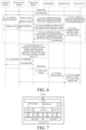
- a processing procedure of a seamless handover between cells of "establishment first and handover later" is implemented based on an N2 interface, as shown in FIG.
- a source base station initiates an HO request message, and a session management function (SMF) entity or an access and mobility management function (AMF) entity on a core network side establishes a protocol data unit (PDU) session (including interaction between a target base station and a core network UPF) on a target side.
- SMF session management function
- AMF access and mobility management function
- the AMF sends an HO Command message to the source base station, and informs the source base station that an HO preparation stage has been completed.
- the UPF begins to send URLLC data to the target base station.
- the data is the same as URLLC data sent by the UPF to the source base station, that is, redundant transmission. As shown by dashed lines in FIG.
- the UPF simultaneously sends same URLLC data to both the source and target base station.
- data sent from the UPF may be cached, and the cached data or a part of the cached data is sent to a terminal device after the connection is established.
- the source base station after receiving the HO Command message sent by the AMF, the source base station sends an HO Command to the terminal device, and triggers the terminal device to perform an air interface handover process on the target base station.
- the terminal device may simultaneously receive the URLLC data from the source and target base stations (i.e., redundant transmission) within a short time.
- the terminal device performs reordering and redundancy removal on the received redundant data, and then delivers the data to an application layer.
- steps 14 to 16 after the air interface handover is completed, the terminal device sends an HO Complete message to a network side, and the network side deletes the connection to the source base station according to the message. The whole handover process is completed.
- step 1A and step 2A are an air interface handover process.
- two IP addresses are allocated for paths of a source base station and a target base station respectively.
- a session 1 corresponding to the source base station and a session 2 corresponding to the target base station a same data flow is transmitted, and a same QoS policy is executed.
- step 3A a session between the target base station and a UPF has been established. The UPF simultaneously sends a same downlink data packet to the source base station and the target base station.
- the target base station may cache or discard a currently received data packet.
- the target base station sends a cached data packet and a real-time downlink data packet to a terminal device.
- steps 5A to 7A a core network device releases a session corresponding to the source base station.
- the present invention provides a data flow processing method.
- the data flow processing method in the embodiments of the present invention may be applied to various communication systems, such as a global system for mobile communication (GSM) system, a code division multiple access (CDMA) system, a wideband code division multiple access (WCDMA) system, a general packet radio service (GPRS), a long term evolution (LTE) system, an LTE frequency division duplex (FDD) system, an LTE time division duplex (TDD) system, a universal mobile telecommunication system (UMTS), a worldwide interoperability for microwave access (WiMAX) communication system, or a 5G system.
- GSM global system for mobile communication
- CDMA code division multiple access
- WCDMA wideband code division multiple access
- GPRS general packet radio service
- LTE long term evolution
- FDD frequency division duplex
- TDD LTE time division duplex
- UMTS universal mobile telecommunication system
- WiMAX worldwide interoperability for microwave access
- the communication system 100 may include a network device 110, and the network device 110 may be a device communicating with a terminal device 120 (or referred to as a communication terminal or a terminal).
- the network device 110 may provide communication coverage for a specific geographical area, and may communicate with a terminal device that is located in the covered area.
- the network device 110 may be a base transceiver station (BTS) in a GSM system or a CDMA system, a NodeB (NB) in a WCDMA system, an evolved NodeB (eNB or eNodeB) in an LTE system, or a wireless controller in a cloud radio access network (CRAN).
- BTS base transceiver station
- NB NodeB
- eNB or eNodeB evolved NodeB
- LTE long term evolution
- the network device may be a network side device in a mobile switching center, a relay station, an access point, an in-vehicle device, a wearable device, a hub, a switch, a bridge, a router, or a 5G network, or may be a network device or the like in a future evolved public land mobile network (PLMN).
- PLMN public land mobile network
- the communication system 100 further includes at least one terminal device 120 located inside a coverage area of the network device 110.
- the "terminal device” used herein includes, but is not limited to, being connected through: a wired line, for example, through a public switched telephone network (PSTN), a digital subscriber line (DSL), a digital cable, or a direct cable; and/or another data connection/network; and/or a wireless interface, for example, for a cellular network, a wireless local area network (WLAN), a digital television network such as a DVB-H network, a satellite network, or an AM-FM broadcast transmitter; and/or an apparatus of another terminal device that is configured to receive/send communication signals; and/or an Internet of Things (IoT) device.
- PSTN public switched telephone network
- DSL digital subscriber line
- a digital cable or a direct cable
- another data connection/network and/or a wireless interface, for example, for a cellular network, a wireless local area network (WLAN), a digital
- the terminal device that is configured to communicate through the wireless interface may be referred to as a "wireless communication terminal", a “wireless terminal”, or a “mobile terminal”.
- An example of the mobile terminal includes, but is not limited to, a satellite or a cellular phone; a personal communication system (PCS) terminal that combines a cellular radio telephone, data processing, fax, and data communication capabilities; a PDA that may include a radio telephone, a beeper, Internet/Intranet access, a web browser, a memo pad, a calendar, and/or a global positioning system (GPS) receiver; and a conventional laptop and/or palmtop receiver or another electronic apparatus including a radio telephone transceiver.
- PCS personal communication system
- GPS global positioning system
- the terminal device may be an access terminal, user equipment (UE), a subscriber unit, a subscriber station, a mobile station, a mobile console, a remote station, a remote terminal, a mobile device, a user terminal, a terminal, a wireless communication device, a user agent, or a user apparatus.
- UE user equipment
- the access terminal may be a cellular phone, a cordless phone, a Session Initiation Protocol (SIP) phone, a wireless local loop (WLL) station, a personal digital assistant (PDA), a handheld device having a wireless communication function, a computing device, another processing device connected to a wireless modem, an in-vehicle device, a wearable device, a terminal device in a 5G network, a terminal device in a future evolved PLMN, or the like.
- SIP Session Initiation Protocol
- WLL wireless local loop
- PDA personal digital assistant
- a 5G system or a 5G network may also be referred to as a new radio (NR) system or an NR network.
- NR new radio
- FIG. 10 illustratively shows one network device and two terminal devices.
- the communication system 100 may include a plurality of network devices, and in a coverage area of each network device, another quantity of terminal devices may be included. This is not limited in this application.
- the communication system 100 may further include other network entities such as a network controller and a mobility management entity. This is not limited in this application.
- a device having a communication function may be referred to as a communication device.
- the communication device may include a network device 110 and a terminal device 120 that each have a communication function.
- the network device 110 and the terminal device 120 can be specific devices described above. Details are not described herein again.
- the communication device may further include other devices in the communication system 100, for example, other network entities such as a network controller and a mobility management entity. This is not limited in this application.
- a processing procedure of a data flow processing method includes the following steps: Step S201.
- An electronic device processes data flow(s) based on first information, where the first information is used to indicate a transmission manner of the data flow(s).
- the electronic device is a core network device.
- the electronic device may also be a base station, or a terminal device.
- the first information may be received by the electronic device, or may be pre-configured.
- the first information is sent by a core network element (such as an SMF).
- the transmission manner of the data flow(s) includes: a manner of performing, by the electronic device, duplication and transmission processing on a data packet in the data flow(s).
- the transmission manner of the data flow(s) further includes: transmitting data flow(s) having a first QFI based on at least two paths; or in an example useful to the understanding of the invention, transmitting a same data packet through data flows having different QFIs.
- the first information is further used to indicate a session identifier ID to which each data flow belongs.
- the transmission manner of the data flow(s) includes: performing redundant transmission on the data flow(s) based on a core network tunnel; and/or preforming redundant transmission on the data flow(s) based on an air interface connection.
- a first manner in which the terminal device performs duplication and transmission processing on a data packet in the data flow(s) includes: sending, by a second PDCP entity of the terminal device, a data packet having a serial number (SN) to a first PDCP entity of the terminal device; and performing, by the first PDCP entity, duplication and transmission processing on the received data packet based on the SN.
- SN serial number
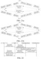
- FIG. 12a is a schematic diagram 1 of the first manner in which the terminal device performs duplication and transmission processing on a data packet in the data flow(s). As shown in FIG. 12a , a QFI of data flow(s) corresponding to a data packet received by a first PDCP entity is the same as that of data flow(s) corresponding to a data packet received by a second PDCP entity.
- FIG. 12a a QFI of data flow(s) corresponding to a data packet received by a first PDCP entity is the same as that of data flow(s) corresponding to a data packet received by a second PDCP entity.
- 12b is a schematic diagram 2 of the first manner in which the terminal device performs duplication and transmission processing on a data packet in the data flow(s), and a QFI of data flow(s) corresponding to a data packet received by a first PDCP entity is different from that of data flow(s) corresponding to a data packet received by a second PDCP entity.
- the first PDCP entity For data for uplink transmission, after receiving a data packet sent by an SDAP entity, the first PDCP entity performs redundancy addition processing on the data packet based on an SN.
- the redundancy addition processing refers to duplicating a data packet in the data flow(s), and/or adding a same SN for a same data packet.
- the redundancy addition processing is that when duplicating a data packet, the first PDCP entity may add a same SN for a same data packet in a layer other than a PDCP layer, for example, an application layer over the PDCP layer. Then, the first PDCP entity sends the duplicated data packet to the second PDCP entity. The first PDCP entity and the second PDCP entity respectively send the data packets to underlying entities corresponding to the first PDCP entity and the second PDCP entity.
- a QFI of data flow(s) corresponding to a data packet received by the first PDCP entity is different from that of data flow(s) corresponding to a data packet received by the second PDCP entity, that is, one PDCP entity serves only one data flow, so that addition of an SN caused by transmission in another data flow on a same PDDP entity can be avoided.
- a set of independent SNs may further be maintained for each data flow.
- data flow(s) that are duplicated and transmitted are mapped to a same DRB ID.
- a first data flow is duplicated to obtain a second data flow and a third data flow, and the first data flow, the second data flow, and the third data flow are configured to have a same DRB ID.
- both the first PDCP entity and the second PDCP entity include the first data flow, the second data flow, and the third data flow.
- the first information herein is used to instruct the second PDCP entity to send a data packet to the first PDCP entity.
- the first information is used to instruct the second PDCP entity to send a data packet corresponding to a second QFI to the first PDCP entity; and/or the first information is used to instruct the second PDCP entity to send a data packet corresponding to a third QFI having a mapping relationship with the second QFI to the first PDCP entity.
- a core network device can explicitly indicate a session performing redundant transmission or a data flow performing redundant transmission, so that the terminal device and a base station can allocate corresponding resources, and trigger corresponding data exchange.
- the mapping relationship between the second QFI and the third QFI is pre-stored.
- the first information is used to instruct the second PDCP entity to send a data packet corresponding to the second QFI to the first PDCP entity, and instructing a third PDCP entity to send a data packet corresponding to the third QFI to the first PDCP entity.
- the first information is used to instruct the second PDCP entity corresponding to a first DRB ID to send the data packet to the first PDCP entity.
- a second manner in which the terminal device performs duplication and transmission processing on a data packet in the data flow(s) includes: performing, by an SDAP entity of the terminal device, duplication and transmission processing on a received data packet based on an SN of a data packet in an SDAP layer.
- the first PDCP entity and the second PDCP entity send the data packets to the SDAP entity.
- the SDAP entity performs redundancy removal and/or reordering on the received data packets based on SNs, and then sends the data packets to an application layer.
- FIG. 13a is a schematic diagram 1 of the second manner in which the terminal device performs duplication and transmission processing on a data packet in the data flow(s).
- a QFI of data flow(s) corresponding to a data packet sent by a first PDCP entity is the same as that of data flow(s) corresponding to a data packet sent by a second PDCP entity.
- FIG. 13b is a schematic diagram 2 of the second manner in which the terminal device performs duplication and transmission processing on a data packet in the data flow(s). As shown in FIG.
- a QFI of data flow(s) corresponding to a data packet sent by a first PDCP entity is different from that of data flow(s) corresponding to a data packet sent by a second PDCP entity.
- an SDAP entity After receiving a data packet sent from an application layer, an SDAP entity performs redundancy addition processing on the data packet based on an SN.
- the redundancy addition processing refers to duplicating a data packet in the data flow(s), and/or adding a same SN for a same data packet.
- the redundancy addition processing is that when duplicating the data packet, the SDAP entity may add a same SN for a same data packet in a layer other than an SDAP layer, for example, an application layer over the SDAP layer. Then, the SDAP entity sends the duplicated data packet to the first PDCP entity and the second PDCP entity. The first PDCP entity and the second PDCP entity respectively send the data packet to underlying entities corresponding to the first PDCP entity and the second PDCP entity. In an example useful to the understanding of the invention, one PDCP entity does not need to serve only one data flow, and an SN is added in a data packet on a transmit end (such as a UPF entity).
- a transmit end such as a UPF entity
- a third manner in which the terminal device performs duplication and transmission processing on a data packet in the data flow(s) includes: respectively receiving, by a first SDAP entity and a second SDAP entity of the terminal device, a first data packet and a second data packet, wherein the first data packet and the second data packet may belong to different sessions; sending, by the second SDAP entity, the second data packet to the first SDAP entity; and performing, by the first SDAP entity, duplication and transmission processing on a data packet based on an SN.
- the first SDAP entity receives the first data packet sent by the first PDCP entity
- the second SDAP entity receives the second data packet sent by the second PDCP entity.
- FIG. 14a is a schematic diagram 1 of the third manner in which the terminal device performs duplication and transmission processing on a data packet in the data flow(s). As shown in FIG. 14a , a QFI of data flow(s) corresponding to a data packet sent by a first PDCP entity is the same as that of data flow(s) corresponding to a data packet sent by a second PDCP entity.
- FIG. 14a a QFI of data flow(s) corresponding to a data packet sent by a first PDCP entity is the same as that of data flow(s) corresponding to a data packet sent by a second PDCP entity.
- 14b is a schematic diagram 2 of the third manner in which the terminal device performs duplication and transmission processing on a data packet in the data flow(s).
- a QFI of data flow(s) corresponding to a data packet sent by a first PDCP entity is different from that of data flow(s) corresponding to a data packet sent by a second PDCP entity.
- a first SDAP entity performs redundancy addition processing.
- the redundancy addition processing refers to duplicating a data packet in the data flow(s), and/or adding a same SN for a same data packet.
- the redundancy addition processing is that when duplicating a data packet, the first SDAP entity may add a same SN for a same data packet in a layer other than an SDAP layer, for example, an application layer over the SDAP layer. Then, the first SDAP entity sends the duplicated data packet to a second SDAP entity. The first SDAP entity and the second SDAP entity respectively send the received data packets to the first PDCP entity and the second PDCP entity.
- FIG. 15 is a schematic diagram 1 of a fourth manner in which the terminal device performs duplication and transmission processing on a data packet in the data flow(s), including: performing, by a first module between a PDCP layer and the SDAP layer, duplication and transmission processing on a data packet based on an SN of a data packet in the PDCP layer.
- the first module is a newly added module between the PDCP layer and the SDAP layer.
- the first module may be an independent hardware module.
- the first module may alternatively belong to a first protocol layer entity corresponding to a newly added first protocol layer between the PDCP layer and the SDAP layer.
- an implementation is that: one or more PDCP entities send specific data for redundant transmission to the first module, and the first module performs redundant transmission processing on a data packet according to an SN of a data packet in the PDCP layer.
- Another implementation is that: one or more PDCP entities send specific data for redundant transmission to the first module, and the first module performs redundant transmission processing on a data packet according to an SN of a data packet in the SDAP layer.
- the first module For data for downlink transmission, after performing redundancy removal/reordering on a data packet sent by the PDCP entity, the first module sends the data packet to the SDAP layer.
- the first module performs redundancy addition processing on a data packet sent by the SDAP entity.
- the redundancy addition processing refers to duplicating a data packet in the data flow(s), and/or adding a same SN for a same data packet.
- the redundancy addition processing is that when duplicating a data packet, the first module may add a same SN for a same data packet in a layer other than a first protocol layer, for example, an application layer over the first protocol layer. Then, the first module sends the duplicated data packet to the PDCP layer.
- the first module may serve one session or more sessions. That is, one first module corresponds to one SDAP entity, or as shown in FIG. 16 , one first module corresponds to two or more SDAP entities.
- FIG. 17 is a schematic diagram 2 of the fourth manner in which the terminal device performs duplication and transmission processing on a data packet in the data flow(s), including: performing, by the second protocol layer entity, duplication and transmission processing on a data packet based on an SN of a data packet in a second protocol layer.
- the second protocol layer corresponding to the second protocol layer entity is located between a PDCP layer and an RLC layer.
- the second protocol layer is a newly added protocol layer between the PDCP layer and the RLC layer.
- FIG. 18 is a schematic diagram 1 of a fifth manner in which the terminal device performs duplication and transmission processing on a data packet in the data flow(s), including: performing, by a second module between an SDAP layer and an application layer of the terminal device, duplication and transmission processing on a data packet based on an SN of a data packet in the SDAP layer.
- the second module is a newly added module between the application layer and the SDAP layer.
- the second module may be an independent hardware module.
- the second module may alternatively belong to a third protocol layer entity corresponding to a newly added third protocol layer between the application layer and the SDAP layer.
- the second module For data for downlink transmission, after performing, according to an SN of a data packet in the SDAP layer, redundancy removal/reordering on a data packet sent by an SDAP entity, the second module sends the data packet to the application layer.
- the second module For data for uplink transmission, the second module performs redundancy addition processing on a data packet sent by an application layer entity.
- the redundancy addition processing refers to duplicating a data packet in the data flow(s), and/or adding a same SN for a same data packet.
- the redundancy addition processing is that when duplicating a data packet, the second module may add a same SN for a same data packet in a layer other than the third protocol layer, for example, an application layer over the third protocol layer.
- the second module sends the duplicated data packet to the SDAP layer.
- the second module may serve one session or more sessions. That is, one second module corresponds to one SDAP entity, or as shown in FIG. 19 , one second module corresponds to two or more SDAP entities.
- FIG. 20 is a schematic diagram 2 of the fifth manner in which the terminal device performs duplication and transmission processing on a data packet in the data flow(s), including: performing, by a third protocol layer entity, duplication and transmission processing on a data packet based on an SN of a data packet in a third protocol layer.
- the third protocol layer corresponding to the third protocol layer entity is located between an SDAP layer and an application layer.
- the first protocol layer may further include a QFI.
- a third protocol layer is also correspondingly added to a UPF on a core network side.
- a data packet is transparently transmitted to the UPF through an access network device, and the UPF performs redundancy processing on the data packet based on an SN, or based on an SN and a QFI. Different data flows may have a same QFI or different QFIs.
- a newly added third protocol layer entity of the UPF performs redundancy addition processing on a data packet based on an SN of a data packet in the third protocol layer, and then transparently transmits the data packets to the terminal device through the access network device.
- the third protocol layer entity of the terminal device performs redundancy removal and/or reordering processing on the data packet based on the SN of the data packet in the third protocol layer.
- a newly added third protocol layer entity of the terminal device For data for uplink transmission, a newly added third protocol layer entity of the terminal device performs redundancy addition processing on a data packet based on an SN of a data packet in the third protocol layer, and then transparently transmits the data packet to the UPF through the access network device.
- the third protocol layer entity of the UPF performs redundancy removal and/or reordering processing on the data packet based on the SN of the data packet in the third protocol layer.
- the electronic device being a base station is used as an example.
- a manner in which a base station performs duplication and transmission processing on a data packet in the data flow(s) includes: adding, by the base station, a same SN for a same data packet; and sending, by the base station, a data packet added with an SN.
- a PDCP entity of the base station adds a same SN for a same data packet; or an SDAP entity of the base station adds a same SN for a same data packet; or a first protocol layer entity corresponding to a first protocol layer between a PDCP layer and an SDAP layer of the base station adds a same SN for a same data packet; or a second protocol layer entity corresponding to a second protocol layer between a PDCP layer and an RLC layer of the base station adds a same SN for a same data packet; or a third protocol layer entity corresponding to a third protocol layer between an SDAP layer and an application layer of the base station adds a same SN for a same data packet.
- FIG. 21a is a schematic diagram 1 showing that a base station performs duplication and transmission processing on a data packet in the data flow(s). As shown in FIG. 21a , two data flows received by the base station have different QFIs.
- FIG. 21b is a schematic diagram 2 showing that a base station performs duplication and transmission processing on a data packet in the data flow(s). As shown in FIG. 21b , two data flows received by the base station have a same FQI.
- a first PDCP entity For data for uplink transmission, after receiving a data packet sent by an SDAP entity, a first PDCP entity performs redundancy addition processing on the data packet based on an SN, that is, duplicates the data packet, adds a same SN for a same data packet, and then sends the duplicated data packet added with the SN to a second PDCP entity.
- the first PDCP entity and the second PDCP entity respectively send the data packets to underlying entities corresponding to the first PDCP entity and the second PDCP entity.
- the base station converts an SN of a data packet in a PDCP layer, an SN of a data packet in an SDAP layer, an SN of a data packet in a first protocol layer between the PDCP layer and the SDAP layer, an SN of a data packet in a second protocol layer between the PDCP layer and an RLC layer, or an SN of a data packet in a third protocol layer between the SDAP layer and an application layer into an SN of a data packet in a GTP-U layer.
- the base station sends the data flow(s) and the converted the SN of the data packet in the GTP-U layer to the UPF entity.
- the electronic device is a core network device (such as a UPF).
- the UPF entity For data for uplink transmission, the UPF entity performs redundancy removal and/or reordering processing on a data packet according to an SN of a data packet in a GTP-U layer and/or a QFI.
- a fourth protocol layer entity of the UPF entity For data for downlink transmission, a fourth protocol layer entity of the UPF entity performs redundancy addition processing on a data packet according to an SN of a data packet in a fourth protocol layer and/or a QFI, that is, duplicates the data packet, adds a same SN for a same data packet, and then sends the duplicated data packet added with the SN.
- the fourth protocol layer corresponding to the fourth protocol layer entity is located over the GTP-U layer.
- the first information is sent by a terminal device, and the first information indicates a protocol layer of the terminal device supporting redundant transmission, for example, an SDAP layer or a PDCP layer, or
- an optional schematic processing flowchart of establishing a session includes the following steps: Step S301.
- a terminal device sends a PDU session establishment request message/modification request message to an access network device.
- the PDU session establishment request message/modification request message carries a first identifier.
- the first identifier is used to indicate whether redundant transmission of data in a PDCP layer or an SDAP layer is supported.
- the first identifier is an NAS message.
- Step S302. The access network device transmits the PDU session establishment request message/modification request message to a core network control plane device.
- Step S303 The core network control plane device determines to perform redundant transmission on specific data.
- the specific data is a data packet corresponding to data flow(s) having a specific QFI.
- Step S304 The core network control plane device transmits the PDU session establishment request message/modification request message to a core network user plane device.
- Step S305 The core network user plane device sends a transmission manner of data flow(s) to a base station or the terminal device.
- the core network user plane device may add all related information of the transmission manner of the data flow(s) to first information, and sends the first information to the base station or the terminal device based on the NAS message.
- the core network user plane device may alternatively add a part of information of the transmission manner of the data flow(s) to first information, and sends the first information to the terminal device or the base station based on the NAS message.
- Another part of information of the transmission manner of the data flow(s) is carried in a second indication, and is sent to the terminal device or the base station through an N2 message.
- Step S306. The terminal device interacts with the base station, to reserve and allocate an air interface resource.
- FIG. 23 a schematic processing flowchart of registration is shown in FIG. 23 .
- a terminal device When sending a registration request to an access network device, a terminal device adds a first indication, and the access network device transparently transmits the first indication to a new AMF.
- the first indication is used to indicate whether redundant transmission of data in a PDCP layer or an SDAP layer is supported.
- a master base station and secondary base station in dual-connectivity can transmit same data packets.
- the transmitted data packets have a same QFI, or in an example useful to the understanding of the invention, the transmitted data packets have different QFIs.
- a handover processing procedure shown in FIG. 25 is the same as the handover processing procedure shown in FIG. 5 .
- a UPF performs redundant transmission on same data packets of a source base station and a target base station.
- a difference is in that: during the handover process in FIG. 25 , transmission is performed on two transmission paths by using a same QFI, or in an example useful to the understanding of the invention by using different QFIs.
- the data flows include a data packet for uplink transmission and a data packet for downlink transmission.
- an embodiment of the present invention further provides an electronic device.
- a composition structure of an electronic device 400 includes a processing unit 402.
- the processing unit 402 is configured to process data flow(s) based on first information, where the first information is used to indicate a transmission manner of the data flow(s).
- the first information may be received by the electronic device 400.
- the first information is pre-configured.
- the electronic device 400 further includes: a transceiver unit 401, configured to receive the first information.
- the transmission manner of the data flow(s) includes: performing, by the processing unit 402, duplication and transmission processing on a data packet in the data flow(s).
- the transmission manner of the data flow(s) includes: transmitting data flow(s) having a first QFI based on at least two paths.
- the transmission manner of the data flow(s) further includes transmitting a same data packet through data flows having different QFIs.
- the first information is further used to indicate a session ID to which each data flow belongs.
- the transmission manner of the data flow(s) includes: performing redundant transmission on the data flow(s) based on a core network tunnel.
- the transmission manner of the data flow(s) further includes preforming redundant transmission on the data flow(s) based on an air interface connection.
- a second PDCP entity of the processing unit 402 sends a data packet having an SN to a first PDCP entity of the processing unit.
- the first PDCP entity performs duplication and transmission processing on the received data packet based on the SN.
- the first information is used to instruct the second PDCP entity to send a data packet to the first PDCP entity.
- the first information is used to instruct the second PDCP entity to send a data packet corresponding to a second QFI to the first PDCP entity; and/or the first information is used to instruct the second PDCP entity to send a data packet corresponding to a third QFI having a mapping relationship with the second QFI to the first PDCP entity.
- the first information is used to instruct the second PDCP entity corresponding to a first DRB ID to send the data packet to the first PDCP entity.
- both the first PDCP entity and the second PDCP entity only transmit data flow(s) corresponding to one QFI.
- each data flow has an independent SN.
- data flow(s) that are duplicated and transmitted are mapped to a same DRB ID.
- an SDAP entity of the processing unit 402 performs duplication and transmission processing on a received data packet based on an SN of a data packet in an SDAP layer.
- a first SDAP entity and a second SDAP entity of the processing unit 402 respectively receive a first data packet and a second data packet.
- the first data packet and the second data packet belong to different sessions.
- the second SDAP entity sends the second data packet to the first SDAP entity.
- the first SDAP entity performs duplication and transmission processing on data packets based on SNs.
- a first module of the processing unit 402 performs duplication and transmission processing on a data packet based on an SN of a data packet in a PDCP layer.
- the first module is located between the PDCP layer and an SDAP layer of the electronic device.
- a first module of the processing unit 402 performs duplication and transmission processing on a data packet based on an SN of a data packet in an SDAP layer.
- the first module is located between a PDCP layer and the SDAP layer of the electronic device.
- a second protocol layer entity of the processing unit 402 performs duplication and transmission processing on a data packet based on an SN of a data packet in a second protocol layer.
- the second protocol layer corresponding to the second protocol layer entity is located between a PDCP layer and an RLC layer of the electronic device.
- a second module of the processing unit 402 performs duplication and transmission processing on a data packet based on an SN of a data packet in an SDAP layer.
- the second module is located between the SDAP layer and an application layer of the electronic device.
- a third protocol layer entity of the processing unit 402 performs duplication and transmission processing on a data packet based on an SN of a data packet in third protocol layer.
- the third protocol layer corresponding to the third protocol layer entity is located between an SDAP layer and an application layer of the electronic device.
- the data packet includes: a data packet for downlink transmission and/or a data packet for uplink transmission.
- the processing unit 402 is configured to: add an SN for a data packet; and send the data packet added with the SN.
- a first protocol layer entity of the processing unit 402 adds an SN for a data packet, where a first protocol layer corresponding to the first protocol layer entity is located between a PDP layer and an SDAP layer of the electronic device; or a second protocol layer entity of the processing unit adds an SN for a data packet, where a second protocol layer corresponding to the second protocol layer entity is located between a PDP layer and an RLC layer of the electronic device; or a third protocol layer entity of the processing unit adds an SN for a data packet, where a third protocol layer corresponding to the third protocol layer entity is located between an SDAP layer and an application layer of the electronic device.
- the processing unit 402 is configured to: convert an SN of a data packet in a PDCP layer, an SN of a data packet in an SDAP layer, an SN of a data packet in a first protocol layer between the PDCP layer and the SDAP layer, an SN of a data packet in a second protocol layer between the PDCP layer and an RLC layer, or an SN of a data packet in a third protocol layer between the SDAP layer and an application layer into an SN of a data packet in a GTP-U layer; and send the data flow(s) and the converted SN of the data packet in the GTP-U layer to a UPF entity.
- the processing unit 402 is configured to perform redundancy removal and/or reordering processing on a data packet according to an SN of a data packet in a GTP-U layer and/or a QFI.
- a fourth protocol layer entity of the processing unit 402 performs redundancy addition processing on a data packet according to an SN of a data packet in a fourth protocol layer and/or a QFI.
- the fourth protocol layer corresponding to the fourth protocol layer entity is located over the GTP-U layer.
- the duplication and transmission processing includes at least one of the following: redundancy addition processing; and redundancy removal and/or reordering.
- Data flow(s) that are duplicated and transmitted have a same QFI or in example useful to the understanding of the invention, data flow(s) that are duplicated and transmitted have different QFIs.
- An example useful to the understanding of the invention further provides a terminal device, including a processor and a memory configured to store a computer program executable on the processor, where the processor is configured to, when running the computer program, perform steps of the data flow processing method performed by the aforesaid terminal device.
- An example useful to the understanding of the invention further provides a base station, including a processor and a memory configured to store a computer program executable on the processor, where the processor is configured to, when running the computer program, perform steps of the data flow processing method performed by the aforesaid base station.
- the present invention further provides a UPF entity, including a processor and a memory configured to store a computer program executable on the processor, where the processor is configured to, when running the computer program, perform steps of the data flow processing method performed by the aforesaid UPF entity.
- a UPF entity including a processor and a memory configured to store a computer program executable on the processor, where the processor is configured to, when running the computer program, perform steps of the data flow processing method performed by the aforesaid UPF entity.
- the data flow processing method provided in the embodiments of the present invention and the electronic device for implementing the data flow processing method provided in the embodiments of the present invention are not only applicable to a handover between intra-system cells, but also applicable to a scenario such as a handover between inter-system cells or LTE/WALN redundant transmission.
- FIG. 27 is a schematic composition structural diagram of hardware of an electronic device (a terminal device, a base station, or a UPF entity) according to the present invention.
- An electronic device 700 includes: at least one processor 701, a memory 702, and at least one network interface 704. All the components in the electronic device 700 are coupled together by using a bus system 705. It may be understood that, the bus system 705 is configured to implement connection and communication between the components. In addition to a data bus, the bus system 705 further includes a power bus, a control bus, and a state signal bus. However, for ease of clear description, all types of buses in FIG. 6 are marked as the bus system 705.
- the memory 702 may be a volatile memory or a non-volatile memory, or may include both a volatile memory and a non-volatile memory.
- the non-volatile memory may be a ROM, a programmable Read-Only Memory (PROM), an erasable programmable read-only memory (EPROM), an electrically erasable programmable read-only memory (EEPROM), a ferromagnetic random access memory (FRAM), a flash memory, a magnetic surface memory, an optical disc, or compact disc read-only memory (CD-ROM).
- the magnetic surface memory may be a magnetic disk memory or a magnetic tape memory.
- the volatile memory may be a random access memory (RAM), used as an external cache.
- RAMs in lots of forms may be used, for example, a static random access memory (SRAM), a synchronous static random access memory (SSRAM), a dynamic random access memory (DRAM), a synchronous dynamic random access memory (SDRAM), a double data rate synchronous dynamic random access memory (DDRSDRAM), an enhanced synchronous dynamic random access memory (ESDRAM), a SyncLink dynamic random access memory (SLDRAM), and a direct Rambus random access memory (DRRAM).
- SRAM static random access memory
- SSRAM synchronous static random access memory
- DRAM dynamic random access memory
- SDRAM synchronous dynamic random access memory
- DDRSDRAM double data rate synchronous dynamic random access memory
- ESDRAM enhanced synchronous dynamic random access memory
- SLDRAM SyncLink dynamic random access memory
- DRRAM direct Rambus random access memory
- the memory 702 in the present invention is configured to store various types of data to support operation of the electronic device 700.
- Examples of the types of data include any computer program to be operated on the electronic device 700, for example, an application program 7022.
- a program for implementing the method in present invention may be included in the application program 7022.
- the method disclosed in the aforesaid embodiment of the present invention may be applied to the processor 701, or implemented by the processor 701.
- the processor 701 may be an integrated circuit chip, having a capability of processing a signal. In an implementation process, steps in the aforesaid methods can be implemented by using a hardware integrated logical circuit in the processor 701, or by using instructions in a form of software.
- the processor 701 may be a general-purpose processor, a digital signal processor (DSP), another programmable logic device, discrete gate or transistor logic device, or discrete hardware assembly, or the like.
- the processor 701 can implement or perform the methods, steps, and logic block diagrams disclosed in the embodiments of the present invention.
- the general purpose processor may be a microprocessor or any conventional processor, or the like.
- the steps in the methods disclosed in the embodiments of the present invention may be directly implemented by a hardware decoding processor, or may be implemented by combining hardware and software modules in a decoding processor.
- the software module may be located in the storage medium.
- the storage medium is located in the memory 702.
- the processor 701 reads information in the memory 702, and completes steps of the aforesaid method in combination with hardware thereof.
- the electronic device 700 may be implemented by using one or more application specific integrated circuits (ASICs), DSPs, programmable logic devices (PLDs), complex programmable logic devices (CPLDs), FPGAs, general-purpose processors, controllers, MCUs, or MPUs, or other electronic components, to perform the aforesaid methods.
- ASICs application specific integrated circuits
- DSPs digital signal processors
- PLDs programmable logic devices
- CPLDs complex programmable logic devices
- FPGAs general-purpose processors
- controllers MCUs, or MPUs, or other electronic components, to perform the aforesaid methods.
- the embodiments of this application further provide a computer-readable storage medium, configured to store a computer program.
- the computer-readable storage medium may be applied to the base station in the examples useful to the understanding of the invention, and the computer storage medium causes the computer to perform corresponding procedures implemented by the base station in various methods in this application. For brevity, details are not described herein again.
- the computer-readable storage medium may be applied to the terminal device in the examples useful to the understanding of the invention, and the computer storage medium causes the computer to perform corresponding procedures implemented by the terminal device in various methods this application. For brevity, details are not described herein again.
- the computer-readable storage medium is applied to the UPF entity in the embodiments of this application, and the computer storage medium causes the computer to perform corresponding procedures implemented by the UPF entity in various methods in the embodiments of this application. For brevity, details are not described herein again.
- These computer program instructions may be provided for a general-purpose computer, a dedicated computer, an embedded processor, or a processor of any other programmable data processing device to generate a machine, so that the instructions executed by a computer or a processor of any other programmable data processing device generate an apparatus for implementing a specific function in one or more processes in the flowcharts and/or in one or more blocks in the block diagrams.
- These computer program instructions may also be stored in a computer-readable memory that can instruct the computer or any other programmable data processing device to work in a specific manner, so that the instructions stored in the computer-readable memory generate an artifact that includes an instruction apparatus.
- the instruction apparatus implements a specific function in one or more processes in the flowcharts and/or in one or more blocks in the block diagrams.
- These computer program instructions may also be loaded onto a computer or another programmable data processing device, so that a series of operations and steps are performed on the computer or the other programmable devices, thereby generating computer-implemented processing. Therefore, the instructions executed on the computer or the another programmable device provide steps for implementing a specific function in one or more processes in the flowcharts and/or in one or more blocks in the block diagrams.
Landscapes
- Engineering & Computer Science (AREA)
- Signal Processing (AREA)
- Computer Networks & Wireless Communication (AREA)
- Computer Security & Cryptography (AREA)
- Mobile Radio Communication Systems (AREA)
Claims (9)
- Procédé de traitement de flux de données, appliqué à une communication ultra-fiable et à faible latence, URLLC, le procédé comprenant :
le traitement (S201), par un dispositif de réseau central, de flux de données sur la base de premières informations, les premières informations étant utilisées pour indiquer une manière de transmission en duplication des flux de données, et la manière de transmission en duplication des flux de données comprenant :la transmission des flux de données ayant un même identifiant de flux de qualité de service, QoS, QFI, via une pluralité d'entités de protocole de convergence de données par paquets, PDCP, en utilisant au moins deux trajets ; etla réalisation d'une transmission redondante sur les flux de données via la pluralité d'entités PDCP sur la base d'un tunnel de réseau central. - Procédé selon la revendication 1, dans lequel la manière de transmission en duplication des flux de données comprend en outre :
une manière de réaliser, par le dispositif de réseau central, un traitement de duplication et de transmission sur un paquet de données dans les flux de données. - Procédé selon la revendication 1, dans lequel le dispositif de réseau central est une entité de fonction de plan utilisateur, UPF ; et pour des données de liaison descendante, l'entité UPF reçoit les premières informations en provenance d'un dispositif terminal ; et l'entité UPF reproduit un paquet de données et attribue un même numéro de séquence, SN, de protocole de tunnellisation de service général de paquets radio, GPRS, GTP, sur l'UPF, GTP-U, au paquet de données pour la transmission redondante.
- Procédé selon la revendication 1, dans lequel le dispositif de réseau central est une entité de fonction de plan utilisateur, UPF ; et pour une donnée de liaison montante qu'il a reçue, l'entité UPF réalise un traitement de retrait de redondance et/ou de réordonnancement sur un paquet de données selon un numéro de séquence, SN, du paquet de données dans un protocole de tunnellisation de service général de radiocommunication par paquets, GPRS, GTP, sur la couche UPF, GTP-U, et/ou le QFI.
- Dispositif de réseau central, appliqué à une communication ultra-fiable et à faible latence, URLLC, le dispositif comprenant :une unité de traitement (402), configurée pour traiter des flux de données sur la base de premières informations, les premières informations étant utilisées pour indiquer une manière de transmission en duplication des flux de données, et la manière de transmission en duplication des flux de données comprenant la transmission des flux de données ayant un même identifiant de flux de qualité de service, QoS, QFI, via une pluralité d'entités de protocole de convergence de données par paquets, PDCP, en utilisant au moins deux trajets ; etla réalisation d'une transmission redondante sur les flux de données via la pluralité d'entités PDCP sur la base d'un tunnel de réseau central.
- Dispositif de réseau central selon la revendication 5, dans lequel la manière de transmission en duplication des flux de données comprend en outre : une manière de réaliser, par l'unité de traitement (402), un traitement de duplication et de transmission sur un paquet de données dans les flux de données.
- Dispositif de réseau central selon la revendication 5, dans lequel le dispositif de réseau central est une entité de fonction de plan utilisateur, UPF ; et pour des données de liaison descendante, l'entité UPF reçoit les premières informations en provenance d'un dispositif terminal ; et l'entité UPF reproduit un paquet de données et attribue un même numéro de séquence, SN, de protocole de tunnellisation de service général de paquets radio, GPRS, GTP, sur l'UPF, GTP-U, au paquet de données pour la transmission redondante.
- Dispositif de réseau central selon la revendication 5, dans lequel le dispositif de réseau central est une entité de fonction de plan utilisateur, UPF ; et pour une donnée de liaison montante qui a reçu, l'entité UPF réalise un traitement de retrait de redondance et/ou de réordonnancement sur un paquet de données selon un numéro de séquence, SN, du paquet de données dans un protocole de tunnellisation de service général de radiocommunication par paquets, GPRS, GTP, sur la couche UPF, GTP-U, et/ou le QFI.
- Support de stockage, stockant un programme exécutable, le programme exécutable, lorsqu'il est exécuté par un processeur, implémentant le procédé de traitement de flux de données selon l'une quelconque des revendications 1 à 4.
Applications Claiming Priority (1)
| Application Number | Priority Date | Filing Date | Title |
|---|---|---|---|
| PCT/CN2019/071676 WO2020146991A1 (fr) | 2019-01-14 | 2019-01-14 | Procédé et dispositif de traitement de flux de données, et support d'informations |
Publications (3)
| Publication Number | Publication Date |
|---|---|
| EP3846372A1 EP3846372A1 (fr) | 2021-07-07 |
| EP3846372A4 EP3846372A4 (fr) | 2021-11-03 |
| EP3846372B1 true EP3846372B1 (fr) | 2024-05-01 |
Family
ID=71613512
Family Applications (1)
| Application Number | Title | Priority Date | Filing Date |
|---|---|---|---|
| EP19910321.9A Active EP3846372B1 (fr) | 2019-01-14 | 2019-01-14 | Procédé et dispositif de traitement de flux de données, et support d'informations |
Country Status (9)
| Country | Link |
|---|---|
| US (1) | US11533138B2 (fr) |
| EP (1) | EP3846372B1 (fr) |
| JP (1) | JP2022516695A (fr) |
| KR (1) | KR20210113591A (fr) |
| CN (2) | CN111787580B (fr) |
| AU (1) | AU2019423298A1 (fr) |
| CA (1) | CA3122886A1 (fr) |
| SG (1) | SG11202106177TA (fr) |
| WO (1) | WO2020146991A1 (fr) |
Families Citing this family (15)
| Publication number | Priority date | Publication date | Assignee | Title |
|---|---|---|---|---|
| US10757615B2 (en) * | 2017-09-13 | 2020-08-25 | Comcast Cable Communications, Llc | Radio link failure information for PDCP duplication |
| US11470532B2 (en) * | 2019-08-16 | 2022-10-11 | Industrial Technology Research Institute | User equipment, communication system, and handling method for handover failure |
| CN113259958A (zh) * | 2020-02-12 | 2021-08-13 | 华为技术有限公司 | 一种数据传输方法及装置 |
| CN114339847B (zh) * | 2020-09-30 | 2024-07-19 | 华为技术有限公司 | 通信方法及装置 |
| EP4210431A4 (fr) * | 2020-09-30 | 2023-11-08 | Huawei Technologies Co., Ltd. | Procédé et appareil de communication |
| WO2022082680A1 (fr) * | 2020-10-22 | 2022-04-28 | 华为技术有限公司 | Procédé et appareil de communication |
| US11729091B2 (en) * | 2020-12-10 | 2023-08-15 | Amazon Technologies, Inc. | Highly available data-processing network functions for radio-based networks |
| CN115278654B (zh) * | 2021-04-30 | 2025-02-18 | 维沃移动通信有限公司 | Rrc连接维护方法、相关设备及可读存储介质 |
| CN115278546B (zh) * | 2021-04-30 | 2025-02-18 | 维沃移动通信有限公司 | 数据传输方法、相关设备及可读存储介质 |
| CN115396961B (zh) * | 2021-05-24 | 2024-11-22 | 中国移动通信集团设计院有限公司 | 基站切换控制方法、装置、设备以及存储介质 |
| CN116017588A (zh) * | 2021-10-21 | 2023-04-25 | 华为技术有限公司 | 通信的方法和装置 |
| WO2023151345A1 (fr) * | 2022-02-08 | 2023-08-17 | 华为技术有限公司 | Procédé de communication, appareil de communication et système de communication |
| JP7816564B2 (ja) * | 2022-04-19 | 2026-02-18 | 1Finity株式会社 | マルチパスの設定方法、装置及びシステム |
| CN118785205A (zh) * | 2023-04-07 | 2024-10-15 | 华为技术有限公司 | 一种通信方法、相关装置、设备以及计算机可读存储介质 |
| CN120785839A (zh) * | 2024-04-04 | 2025-10-14 | 腾讯科技(深圳)有限公司 | 数据传输方法、装置、计算机可读介质及电子设备 |
Family Cites Families (47)
| Publication number | Priority date | Publication date | Assignee | Title |
|---|---|---|---|---|
| US8189588B2 (en) * | 2009-03-13 | 2012-05-29 | Cisco Technology, Inc. | Flow resiliency |
| US8949582B2 (en) * | 2009-04-27 | 2015-02-03 | Lsi Corporation | Changing a flow identifier of a packet in a multi-thread, multi-flow network processor |
| US9462581B2 (en) * | 2012-10-16 | 2016-10-04 | Qualcomm Incorporated | Methods and apparatus for synchronously coded subcarriers in OFDMA systems |
| CN103001748B (zh) * | 2012-12-25 | 2015-10-14 | 大唐移动通信设备有限公司 | 一种数据重传以及重传数据处理的方法、设备 |
| CN103634299B (zh) * | 2013-11-14 | 2016-09-14 | 北京邮电大学 | 基于多连接的实时流媒体传输终端与方法 |
| CN106304401B (zh) * | 2015-05-22 | 2020-06-02 | 华为技术有限公司 | 一种公共wlan架构下的数据隧道建立方法和ap |
| CN105933232B (zh) * | 2016-03-29 | 2018-10-23 | 东北大学 | 支持多业务数据传输需求的多径传输控制终端及方法 |
| US10778779B2 (en) * | 2016-06-17 | 2020-09-15 | Huawei Technologies Co., Ltd. | Method and system for session management for ultra reliable and low latency communications in high mobility scenarios |
| US10225046B2 (en) * | 2017-01-09 | 2019-03-05 | At&T Intellectual Property I, L.P. | Adaptive cyclic redundancy check for uplink control information encoding |
| US10856174B2 (en) * | 2017-03-16 | 2020-12-01 | Ofinno, Llc | Buffer status report control |
| US10863380B2 (en) * | 2017-03-16 | 2020-12-08 | Ofinno, Llc | Buffer status reporting procedure in a wireless device and wireless network |
| JP6881722B2 (ja) * | 2017-03-16 | 2021-06-02 | オフィノ, エルエルシー | 切り捨てられたバッファステータスレポーティング |
| US10506659B2 (en) * | 2017-03-23 | 2019-12-10 | Kt Corporation | Method for processing radio link failure and apparatus therefor |
| US10716094B2 (en) * | 2017-03-23 | 2020-07-14 | Ofinno, Llc | Packet duplication in a wireless device and wireless network |
| EP3602859A1 (fr) * | 2017-03-23 | 2020-02-05 | Fraunhofer-Gesellschaft zur Förderung der angewandten Forschung e.V. | Transmission fiable de paquets de données entre des entités d'un réseau d'accès radio d'un réseau de communication mobile |
| US10873911B2 (en) * | 2017-03-23 | 2020-12-22 | Ofinno, LCC | Uplink transmission power adjustment |
| CN112738858B (zh) * | 2017-03-24 | 2022-05-31 | 华为技术有限公司 | 切换的方法和设备 |
| CN108631980B (zh) * | 2017-03-24 | 2021-03-05 | 电信科学技术研究院 | 数据传输方法、终端、网络侧设备和计算机可读存储介质 |
| CN107439037A (zh) * | 2017-04-25 | 2017-12-05 | 北京小米移动软件有限公司 | 缓存状态的上报方法及装置 |
| WO2018196102A1 (fr) * | 2017-04-27 | 2018-11-01 | 北京小米移动软件有限公司 | Procédé et appareil de transmission d'informations et support de stockage lisible par ordinateur |
| KR102318015B1 (ko) * | 2017-04-28 | 2021-10-27 | 삼성전자 주식회사 | 무선통신시스템에서 데이터 종류에 따른 길이를 지시하는 방법 및 장치 |
| US10973071B2 (en) * | 2017-05-02 | 2021-04-06 | Nokia Solutions And Networks Oy | Improving communication reliability |
| US10805836B2 (en) * | 2017-05-05 | 2020-10-13 | Qualcomm Incorporated | Packet duplication at a packet data convergence protocol (PDCP) entity |
| CN108874530B (zh) * | 2017-05-12 | 2020-11-06 | 华为技术有限公司 | 对报文转发设备的业务板进行扩容、缩容的方法和装置 |
| US20180352601A1 (en) * | 2017-05-31 | 2018-12-06 | Electronics And Telecommunications Research Institute | Method for communicating in mobile communication system and apparatus for the same |
| WO2018230849A1 (fr) * | 2017-06-14 | 2018-12-20 | Lg Electronics Inc. | Procédé de gestion de la désactivation pour une cellule dans laquelle une duplication de paquets est effectuée dans un système de communication sans fil et dispositif associé |
| US20180367288A1 (en) * | 2017-06-16 | 2018-12-20 | Huawei Technologies Co., Ltd. | Dynamic activation and deactivation of packet duplication |
| CN108401505B (zh) * | 2017-06-20 | 2021-10-15 | 北京小米移动软件有限公司 | 功能配置方法及装置、消息发送方法及装置和用户设备 |
| EP3643110A4 (fr) * | 2017-06-20 | 2021-03-10 | Apple Inc. | Dispositifs et procédés de déclenchement de contrôle de flux et de renvoi d'informations |
| EP3422676A1 (fr) * | 2017-06-27 | 2019-01-02 | Thomson Licensing | Procédé et dispositif destinés à transférer un paquet de données |
| CN111034294A (zh) * | 2017-08-08 | 2020-04-17 | 三菱电机株式会社 | 通信系统、通信终端装置及基站装置 |
| WO2019036862A1 (fr) * | 2017-08-21 | 2019-02-28 | 北京小米移动软件有限公司 | Procédé et dispositif de transmission de données |
| KR102472292B1 (ko) * | 2018-01-10 | 2022-11-30 | 삼성전자 주식회사 | 무선 통신 시스템에서 경쟁 및 비경쟁 기반 빔 실패 복구를 수행하는 방법 및 장치 |
| CN110072253B (zh) * | 2018-01-22 | 2020-12-18 | 华为技术有限公司 | 通信方法、装置和系统 |
| US10827380B2 (en) * | 2018-01-30 | 2020-11-03 | Huawei Technologies Co., Ltd. | System and method for supporting URLLC in advanced V2X communications |
| KR102327208B1 (ko) * | 2018-02-13 | 2021-11-16 | 삼성전자주식회사 | 이동통신 시스템에서 셀 재선택을 수행하는 방법 및 장치 |
| US10986528B2 (en) * | 2018-02-15 | 2021-04-20 | Huawei Technologies Co., Ltd. | Tracking QoS violated events |
| EP3755097B1 (fr) * | 2018-02-15 | 2024-02-21 | Fujitsu Limited | Dispositif de transmission, procédé de communication sans fil, système de communication sans fil et récepteur |
| CN110351024B (zh) * | 2018-04-04 | 2021-06-15 | 华为技术有限公司 | 数据传输方法和装置 |
| US11258549B2 (en) * | 2018-05-10 | 2022-02-22 | Comcast Cable Communications, Llc | Packet duplication control |
| US10904947B2 (en) * | 2018-05-16 | 2021-01-26 | Huawei Technologies Co., Ltd. | Message and system for application function influence on traffic routing |
| KR102510823B1 (ko) * | 2018-08-13 | 2023-03-16 | 삼성전자주식회사 | 이동통신 시스템에서 핸드오버 방법 및 장치 |
| US11304092B2 (en) * | 2018-09-12 | 2022-04-12 | Ofinno, Llc | Session packet duplication control |
| US11399304B2 (en) * | 2018-09-28 | 2022-07-26 | Ofinno, Llc | Packet duplication by core network |
| US11678252B2 (en) * | 2018-10-05 | 2023-06-13 | Huawei Technologies Co., Ltd. | Quality of service information notification to user equipment, users, and application server |
| US11184275B2 (en) * | 2018-11-16 | 2021-11-23 | Huawei Technologies Co., Ltd. | System and method for transmission redundancy in wireless communications |
| US20210105196A1 (en) * | 2019-10-04 | 2021-04-08 | Huawei Technologies Co., Ltd. | Support group communications with shared downlink data |
-
2019
- 2019-01-14 EP EP19910321.9A patent/EP3846372B1/fr active Active
- 2019-01-14 KR KR1020217017114A patent/KR20210113591A/ko not_active Withdrawn
- 2019-01-14 WO PCT/CN2019/071676 patent/WO2020146991A1/fr not_active Ceased
- 2019-01-14 CA CA3122886A patent/CA3122886A1/fr not_active Abandoned
- 2019-01-14 CN CN202010592566.3A patent/CN111787580B/zh active Active
- 2019-01-14 JP JP2021531667A patent/JP2022516695A/ja active Pending
- 2019-01-14 CN CN201980005901.0A patent/CN111699649A/zh active Pending
- 2019-01-14 AU AU2019423298A patent/AU2019423298A1/en not_active Abandoned
- 2019-01-14 SG SG11202106177TA patent/SG11202106177TA/en unknown
-
2021
- 2021-05-03 US US17/306,696 patent/US11533138B2/en active Active
Also Published As
| Publication number | Publication date |
|---|---|
| CN111787580A (zh) | 2020-10-16 |
| CA3122886A1 (fr) | 2020-07-23 |
| KR20210113591A (ko) | 2021-09-16 |
| SG11202106177TA (en) | 2021-07-29 |
| CN111699649A (zh) | 2020-09-22 |
| AU2019423298A1 (en) | 2021-07-01 |
| EP3846372A4 (fr) | 2021-11-03 |
| WO2020146991A1 (fr) | 2020-07-23 |
| JP2022516695A (ja) | 2022-03-02 |
| US20210258111A1 (en) | 2021-08-19 |
| EP3846372A1 (fr) | 2021-07-07 |
| US11533138B2 (en) | 2022-12-20 |
| CN111787580B (zh) | 2022-05-24 |
Similar Documents
| Publication | Publication Date | Title |
|---|---|---|
| EP3846372B1 (fr) | Procédé et dispositif de traitement de flux de données, et support d'informations | |
| US11665601B2 (en) | Method for handover report and terminal device | |
| US12598487B2 (en) | Slicing method and apparatus, storage medium, and processor | |
| US11974172B2 (en) | Service node updating method, terminal device, and network-side device | |
| CN114258715B (zh) | 一种切换处理方法、网络设备 | |
| CN113647144B (zh) | 一种条件切换指示方法、终端设备、源基站及存储介质 | |
| CN114270935B (zh) | 一种小区连接方法、电子设备及存储介质 | |
| US11805563B2 (en) | Wireless communication method and base station | |
| US11611925B2 (en) | Switching processing method, terminal device and network device | |
| WO2020248283A1 (fr) | Procédé et dispositif de communication sans fil, et dispositif terminal | |
| WO2020024301A1 (fr) | Procédé et dispositif permettant d'assurer la fiabilité de transmission de données, et appareil de réseau | |
| WO2020163999A1 (fr) | Procédé de communication sans fil et dispositif | |
| CN112789889B (zh) | 一种无线资源控制消息的处理方法、设备及存储介质 | |
| WO2020024296A1 (fr) | Procédé et appareil de commutation de station de base, et dispositif de réseau | |
| EP4007369B1 (fr) | Procédé de traitement d'informations et dispositif terminal | |
| CN112514450B (zh) | 一种数据处理方法、设备及存储介质 | |
| WO2020223909A1 (fr) | Procédé de gestion de contexte, dispositif et support d'informations | |
| CN111989951B (zh) | 一种数据转发方法及装置、网络设备 | |
| WO2021007758A1 (fr) | Procédé d'acquisition de paramètres, et dispositif et support d'enregistrement | |
| CN113078990A (zh) | 一种数据处理方法、终端设备及存储介质 |
Legal Events
| Date | Code | Title | Description |
|---|---|---|---|
| STAA | Information on the status of an ep patent application or granted ep patent |
Free format text: STATUS: THE INTERNATIONAL PUBLICATION HAS BEEN MADE |
|
| STAA | Information on the status of an ep patent application or granted ep patent |
Free format text: STATUS: REQUEST FOR EXAMINATION WAS MADE |
|
| PUAI | Public reference made under article 153(3) epc to a published international application that has entered the european phase |
Free format text: ORIGINAL CODE: 0009012 |
|
| 17P | Request for examination filed |
Effective date: 20210401 |
|
| AK | Designated contracting states |
Kind code of ref document: A1 Designated state(s): AL AT BE BG CH CY CZ DE DK EE ES FI FR GB GR HR HU IE IS IT LI LT LU LV MC MK MT NL NO PL PT RO RS SE SI SK SM TR |
|
| A4 | Supplementary search report drawn up and despatched |
Effective date: 20211005 |
|
| RIC1 | Information provided on ipc code assigned before grant |
Ipc: H04L 1/08 20060101ALI20210929BHEP Ipc: H04L 1/22 20060101ALI20210929BHEP Ipc: H04L 5/00 20060101AFI20210929BHEP |
|
| DAV | Request for validation of the european patent (deleted) | ||
| DAX | Request for extension of the european patent (deleted) | ||
| STAA | Information on the status of an ep patent application or granted ep patent |
Free format text: STATUS: EXAMINATION IS IN PROGRESS |
|
| 17Q | First examination report despatched |
Effective date: 20220520 |
|
| GRAP | Despatch of communication of intention to grant a patent |
Free format text: ORIGINAL CODE: EPIDOSNIGR1 |
|
| STAA | Information on the status of an ep patent application or granted ep patent |
Free format text: STATUS: GRANT OF PATENT IS INTENDED |
|
| INTG | Intention to grant announced |
Effective date: 20231009 |
|
| GRAJ | Information related to disapproval of communication of intention to grant by the applicant or resumption of examination proceedings by the epo deleted |
Free format text: ORIGINAL CODE: EPIDOSDIGR1 |
|
| STAA | Information on the status of an ep patent application or granted ep patent |
Free format text: STATUS: EXAMINATION IS IN PROGRESS |
|
| INTC | Intention to grant announced (deleted) | ||
| GRAS | Grant fee paid |
Free format text: ORIGINAL CODE: EPIDOSNIGR3 |
|
| STAA | Information on the status of an ep patent application or granted ep patent |
Free format text: STATUS: GRANT OF PATENT IS INTENDED |
|
| GRAP | Despatch of communication of intention to grant a patent |
Free format text: ORIGINAL CODE: EPIDOSNIGR1 |
|
| GRAA | (expected) grant |
Free format text: ORIGINAL CODE: 0009210 |
|
| STAA | Information on the status of an ep patent application or granted ep patent |
Free format text: STATUS: THE PATENT HAS BEEN GRANTED |
|
| INTG | Intention to grant announced |
Effective date: 20240319 |
|
| AK | Designated contracting states |
Kind code of ref document: B1 Designated state(s): AL AT BE BG CH CY CZ DE DK EE ES FI FR GB GR HR HU IE IS IT LI LT LU LV MC MK MT NL NO PL PT RO RS SE SI SK SM TR |
|
| REG | Reference to a national code |
Ref country code: GB Ref legal event code: FG4D |
|
| REG | Reference to a national code |
Ref country code: CH Ref legal event code: EP |
|
| REG | Reference to a national code |
Ref country code: IE Ref legal event code: FG4D |
|
| REG | Reference to a national code |
Ref country code: DE Ref legal event code: R096 Ref document number: 602019051727 Country of ref document: DE |
|
| P01 | Opt-out of the competence of the unified patent court (upc) registered |
Effective date: 20240521 |
|
| REG | Reference to a national code |
Ref country code: LT Ref legal event code: MG9D |
|
| REG | Reference to a national code |
Ref country code: NL Ref legal event code: MP Effective date: 20240501 |
|
| PG25 | Lapsed in a contracting state [announced via postgrant information from national office to epo] |
Ref country code: IS Free format text: LAPSE BECAUSE OF FAILURE TO SUBMIT A TRANSLATION OF THE DESCRIPTION OR TO PAY THE FEE WITHIN THE PRESCRIBED TIME-LIMIT Effective date: 20240901 |
|
| PG25 | Lapsed in a contracting state [announced via postgrant information from national office to epo] |
Ref country code: BG Free format text: LAPSE BECAUSE OF FAILURE TO SUBMIT A TRANSLATION OF THE DESCRIPTION OR TO PAY THE FEE WITHIN THE PRESCRIBED TIME-LIMIT Effective date: 20240501 |
|
| PG25 | Lapsed in a contracting state [announced via postgrant information from national office to epo] |
Ref country code: HR Free format text: LAPSE BECAUSE OF FAILURE TO SUBMIT A TRANSLATION OF THE DESCRIPTION OR TO PAY THE FEE WITHIN THE PRESCRIBED TIME-LIMIT Effective date: 20240501 Ref country code: FI Free format text: LAPSE BECAUSE OF FAILURE TO SUBMIT A TRANSLATION OF THE DESCRIPTION OR TO PAY THE FEE WITHIN THE PRESCRIBED TIME-LIMIT Effective date: 20240501 |
|
| PG25 | Lapsed in a contracting state [announced via postgrant information from national office to epo] |
Ref country code: GR Free format text: LAPSE BECAUSE OF FAILURE TO SUBMIT A TRANSLATION OF THE DESCRIPTION OR TO PAY THE FEE WITHIN THE PRESCRIBED TIME-LIMIT Effective date: 20240802 |
|
| PG25 | Lapsed in a contracting state [announced via postgrant information from national office to epo] |
Ref country code: PT Free format text: LAPSE BECAUSE OF FAILURE TO SUBMIT A TRANSLATION OF THE DESCRIPTION OR TO PAY THE FEE WITHIN THE PRESCRIBED TIME-LIMIT Effective date: 20240902 |
|
| REG | Reference to a national code |
Ref country code: AT Ref legal event code: MK05 Ref document number: 1683841 Country of ref document: AT Kind code of ref document: T Effective date: 20240501 |
|
| PG25 | Lapsed in a contracting state [announced via postgrant information from national office to epo] |
Ref country code: NL Free format text: LAPSE BECAUSE OF FAILURE TO SUBMIT A TRANSLATION OF THE DESCRIPTION OR TO PAY THE FEE WITHIN THE PRESCRIBED TIME-LIMIT Effective date: 20240501 |
|
| PG25 | Lapsed in a contracting state [announced via postgrant information from national office to epo] |
Ref country code: ES Free format text: LAPSE BECAUSE OF FAILURE TO SUBMIT A TRANSLATION OF THE DESCRIPTION OR TO PAY THE FEE WITHIN THE PRESCRIBED TIME-LIMIT Effective date: 20240501 |
|
| PG25 | Lapsed in a contracting state [announced via postgrant information from national office to epo] |
Ref country code: AT Free format text: LAPSE BECAUSE OF FAILURE TO SUBMIT A TRANSLATION OF THE DESCRIPTION OR TO PAY THE FEE WITHIN THE PRESCRIBED TIME-LIMIT Effective date: 20240501 |
|
| PG25 | Lapsed in a contracting state [announced via postgrant information from national office to epo] |
Ref country code: PL Free format text: LAPSE BECAUSE OF FAILURE TO SUBMIT A TRANSLATION OF THE DESCRIPTION OR TO PAY THE FEE WITHIN THE PRESCRIBED TIME-LIMIT Effective date: 20240501 |
|
| PG25 | Lapsed in a contracting state [announced via postgrant information from national office to epo] |
Ref country code: LV Free format text: LAPSE BECAUSE OF FAILURE TO SUBMIT A TRANSLATION OF THE DESCRIPTION OR TO PAY THE FEE WITHIN THE PRESCRIBED TIME-LIMIT Effective date: 20240501 |
|
| PG25 | Lapsed in a contracting state [announced via postgrant information from national office to epo] |
Ref country code: PT Free format text: LAPSE BECAUSE OF FAILURE TO SUBMIT A TRANSLATION OF THE DESCRIPTION OR TO PAY THE FEE WITHIN THE PRESCRIBED TIME-LIMIT Effective date: 20240902 Ref country code: PL Free format text: LAPSE BECAUSE OF FAILURE TO SUBMIT A TRANSLATION OF THE DESCRIPTION OR TO PAY THE FEE WITHIN THE PRESCRIBED TIME-LIMIT Effective date: 20240501 Ref country code: NO Free format text: LAPSE BECAUSE OF FAILURE TO SUBMIT A TRANSLATION OF THE DESCRIPTION OR TO PAY THE FEE WITHIN THE PRESCRIBED TIME-LIMIT Effective date: 20240801 Ref country code: NL Free format text: LAPSE BECAUSE OF FAILURE TO SUBMIT A TRANSLATION OF THE DESCRIPTION OR TO PAY THE FEE WITHIN THE PRESCRIBED TIME-LIMIT Effective date: 20240501 Ref country code: LV Free format text: LAPSE BECAUSE OF FAILURE TO SUBMIT A TRANSLATION OF THE DESCRIPTION OR TO PAY THE FEE WITHIN THE PRESCRIBED TIME-LIMIT Effective date: 20240501 Ref country code: IS Free format text: LAPSE BECAUSE OF FAILURE TO SUBMIT A TRANSLATION OF THE DESCRIPTION OR TO PAY THE FEE WITHIN THE PRESCRIBED TIME-LIMIT Effective date: 20240901 Ref country code: HR Free format text: LAPSE BECAUSE OF FAILURE TO SUBMIT A TRANSLATION OF THE DESCRIPTION OR TO PAY THE FEE WITHIN THE PRESCRIBED TIME-LIMIT Effective date: 20240501 Ref country code: GR Free format text: LAPSE BECAUSE OF FAILURE TO SUBMIT A TRANSLATION OF THE DESCRIPTION OR TO PAY THE FEE WITHIN THE PRESCRIBED TIME-LIMIT Effective date: 20240802 Ref country code: FI Free format text: LAPSE BECAUSE OF FAILURE TO SUBMIT A TRANSLATION OF THE DESCRIPTION OR TO PAY THE FEE WITHIN THE PRESCRIBED TIME-LIMIT Effective date: 20240501 Ref country code: ES Free format text: LAPSE BECAUSE OF FAILURE TO SUBMIT A TRANSLATION OF THE DESCRIPTION OR TO PAY THE FEE WITHIN THE PRESCRIBED TIME-LIMIT Effective date: 20240501 Ref country code: BG Free format text: LAPSE BECAUSE OF FAILURE TO SUBMIT A TRANSLATION OF THE DESCRIPTION OR TO PAY THE FEE WITHIN THE PRESCRIBED TIME-LIMIT Effective date: 20240501 Ref country code: AT Free format text: LAPSE BECAUSE OF FAILURE TO SUBMIT A TRANSLATION OF THE DESCRIPTION OR TO PAY THE FEE WITHIN THE PRESCRIBED TIME-LIMIT Effective date: 20240501 Ref country code: RS Free format text: LAPSE BECAUSE OF FAILURE TO SUBMIT A TRANSLATION OF THE DESCRIPTION OR TO PAY THE FEE WITHIN THE PRESCRIBED TIME-LIMIT Effective date: 20240801 |
|
| PG25 | Lapsed in a contracting state [announced via postgrant information from national office to epo] |
Ref country code: DK Free format text: LAPSE BECAUSE OF FAILURE TO SUBMIT A TRANSLATION OF THE DESCRIPTION OR TO PAY THE FEE WITHIN THE PRESCRIBED TIME-LIMIT Effective date: 20240501 |
|
| PG25 | Lapsed in a contracting state [announced via postgrant information from national office to epo] |
Ref country code: EE Free format text: LAPSE BECAUSE OF FAILURE TO SUBMIT A TRANSLATION OF THE DESCRIPTION OR TO PAY THE FEE WITHIN THE PRESCRIBED TIME-LIMIT Effective date: 20240501 |
|
| PG25 | Lapsed in a contracting state [announced via postgrant information from national office to epo] |
Ref country code: CZ Free format text: LAPSE BECAUSE OF FAILURE TO SUBMIT A TRANSLATION OF THE DESCRIPTION OR TO PAY THE FEE WITHIN THE PRESCRIBED TIME-LIMIT Effective date: 20240501 |
|
| PG25 | Lapsed in a contracting state [announced via postgrant information from national office to epo] |
Ref country code: SK Free format text: LAPSE BECAUSE OF FAILURE TO SUBMIT A TRANSLATION OF THE DESCRIPTION OR TO PAY THE FEE WITHIN THE PRESCRIBED TIME-LIMIT Effective date: 20240501 Ref country code: RO Free format text: LAPSE BECAUSE OF FAILURE TO SUBMIT A TRANSLATION OF THE DESCRIPTION OR TO PAY THE FEE WITHIN THE PRESCRIBED TIME-LIMIT Effective date: 20240501 |
|
| PG25 | Lapsed in a contracting state [announced via postgrant information from national office to epo] |
Ref country code: SM Free format text: LAPSE BECAUSE OF FAILURE TO SUBMIT A TRANSLATION OF THE DESCRIPTION OR TO PAY THE FEE WITHIN THE PRESCRIBED TIME-LIMIT Effective date: 20240501 |
|
| PG25 | Lapsed in a contracting state [announced via postgrant information from national office to epo] |
Ref country code: SM Free format text: LAPSE BECAUSE OF FAILURE TO SUBMIT A TRANSLATION OF THE DESCRIPTION OR TO PAY THE FEE WITHIN THE PRESCRIBED TIME-LIMIT Effective date: 20240501 Ref country code: SK Free format text: LAPSE BECAUSE OF FAILURE TO SUBMIT A TRANSLATION OF THE DESCRIPTION OR TO PAY THE FEE WITHIN THE PRESCRIBED TIME-LIMIT Effective date: 20240501 Ref country code: RO Free format text: LAPSE BECAUSE OF FAILURE TO SUBMIT A TRANSLATION OF THE DESCRIPTION OR TO PAY THE FEE WITHIN THE PRESCRIBED TIME-LIMIT Effective date: 20240501 Ref country code: EE Free format text: LAPSE BECAUSE OF FAILURE TO SUBMIT A TRANSLATION OF THE DESCRIPTION OR TO PAY THE FEE WITHIN THE PRESCRIBED TIME-LIMIT Effective date: 20240501 Ref country code: DK Free format text: LAPSE BECAUSE OF FAILURE TO SUBMIT A TRANSLATION OF THE DESCRIPTION OR TO PAY THE FEE WITHIN THE PRESCRIBED TIME-LIMIT Effective date: 20240501 Ref country code: CZ Free format text: LAPSE BECAUSE OF FAILURE TO SUBMIT A TRANSLATION OF THE DESCRIPTION OR TO PAY THE FEE WITHIN THE PRESCRIBED TIME-LIMIT Effective date: 20240501 |
|
| REG | Reference to a national code |
Ref country code: DE Ref legal event code: R097 Ref document number: 602019051727 Country of ref document: DE |
|
| PG25 | Lapsed in a contracting state [announced via postgrant information from national office to epo] |
Ref country code: IT Free format text: LAPSE BECAUSE OF FAILURE TO SUBMIT A TRANSLATION OF THE DESCRIPTION OR TO PAY THE FEE WITHIN THE PRESCRIBED TIME-LIMIT Effective date: 20240501 |
|
| PLBE | No opposition filed within time limit |
Free format text: ORIGINAL CODE: 0009261 |
|
| STAA | Information on the status of an ep patent application or granted ep patent |
Free format text: STATUS: NO OPPOSITION FILED WITHIN TIME LIMIT |
|
| 26N | No opposition filed |
Effective date: 20250204 |
|
| PG25 | Lapsed in a contracting state [announced via postgrant information from national office to epo] |
Ref country code: SI Free format text: LAPSE BECAUSE OF FAILURE TO SUBMIT A TRANSLATION OF THE DESCRIPTION OR TO PAY THE FEE WITHIN THE PRESCRIBED TIME-LIMIT Effective date: 20240501 |
|
| REG | Reference to a national code |
Ref country code: DE Ref legal event code: R119 Ref document number: 602019051727 Country of ref document: DE |
|
| REG | Reference to a national code |
Ref country code: CH Ref legal event code: PL |
|
| PG25 | Lapsed in a contracting state [announced via postgrant information from national office to epo] |
Ref country code: SE Free format text: LAPSE BECAUSE OF FAILURE TO SUBMIT A TRANSLATION OF THE DESCRIPTION OR TO PAY THE FEE WITHIN THE PRESCRIBED TIME-LIMIT Effective date: 20240501 |
|
| PG25 | Lapsed in a contracting state [announced via postgrant information from national office to epo] |
Ref country code: MC Free format text: LAPSE BECAUSE OF FAILURE TO SUBMIT A TRANSLATION OF THE DESCRIPTION OR TO PAY THE FEE WITHIN THE PRESCRIBED TIME-LIMIT Effective date: 20240501 Ref country code: LU Free format text: LAPSE BECAUSE OF NON-PAYMENT OF DUE FEES Effective date: 20250114 |
|
| PG25 | Lapsed in a contracting state [announced via postgrant information from national office to epo] |
Ref country code: DE Free format text: LAPSE BECAUSE OF NON-PAYMENT OF DUE FEES Effective date: 20250801 |
|
| PG25 | Lapsed in a contracting state [announced via postgrant information from national office to epo] |
Ref country code: BE Free format text: LAPSE BECAUSE OF NON-PAYMENT OF DUE FEES Effective date: 20250131 |
|
| PG25 | Lapsed in a contracting state [announced via postgrant information from national office to epo] |
Ref country code: FR Free format text: LAPSE BECAUSE OF NON-PAYMENT OF DUE FEES Effective date: 20250131 |
|
| PG25 | Lapsed in a contracting state [announced via postgrant information from national office to epo] |
Ref country code: CH Free format text: LAPSE BECAUSE OF NON-PAYMENT OF DUE FEES Effective date: 20250131 |
|
| REG | Reference to a national code |
Ref country code: BE Ref legal event code: MM Effective date: 20250131 |
|
| PG25 | Lapsed in a contracting state [announced via postgrant information from national office to epo] |
Ref country code: IE Free format text: LAPSE BECAUSE OF NON-PAYMENT OF DUE FEES Effective date: 20250114 |
|
| PGFP | Annual fee paid to national office [announced via postgrant information from national office to epo] |
Ref country code: GB Payment date: 20260123 Year of fee payment: 8 |