EP3846376B1 - Modèle de saut spécifique pour l'envoi et la réception répétés des données - Google Patents
Modèle de saut spécifique pour l'envoi et la réception répétés des données Download PDFInfo
- Publication number
- EP3846376B1 EP3846376B1 EP21158768.8A EP21158768A EP3846376B1 EP 3846376 B1 EP3846376 B1 EP 3846376B1 EP 21158768 A EP21158768 A EP 21158768A EP 3846376 B1 EP3846376 B1 EP 3846376B1
- Authority
- EP
- European Patent Office
- Prior art keywords
- hopping pattern
- data
- time
- hop
- frequency
- Prior art date
- Legal status (The legal status is an assumption and is not a legal conclusion. Google has not performed a legal analysis and makes no representation as to the accuracy of the status listed.)
- Active
Links
Images






Classifications
-
- H—ELECTRICITY
- H04—ELECTRIC COMMUNICATION TECHNIQUE
- H04B—TRANSMISSION
- H04B1/00—Details of transmission systems, not covered by a single one of groups H04B3/00 - H04B13/00; Details of transmission systems not characterised by the medium used for transmission
- H04B1/69—Spread spectrum techniques
- H04B1/713—Spread spectrum techniques using frequency hopping
- H04B1/7143—Arrangements for generation of hop patterns
-
- H—ELECTRICITY
- H04—ELECTRIC COMMUNICATION TECHNIQUE
- H04L—TRANSMISSION OF DIGITAL INFORMATION, e.g. TELEGRAPHIC COMMUNICATION
- H04L5/00—Arrangements affording multiple use of the transmission path
- H04L5/0001—Arrangements for dividing the transmission path
- H04L5/0003—Two-dimensional division
- H04L5/0005—Time-frequency
- H04L5/0007—Time-frequency the frequencies being orthogonal, e.g. OFDM(A) or DMT
- H04L5/0012—Hopping in multicarrier systems
-
- H—ELECTRICITY
- H04—ELECTRIC COMMUNICATION TECHNIQUE
- H04B—TRANSMISSION
- H04B1/00—Details of transmission systems, not covered by a single one of groups H04B3/00 - H04B13/00; Details of transmission systems not characterised by the medium used for transmission
- H04B1/69—Spread spectrum techniques
- H04B1/713—Spread spectrum techniques using frequency hopping
- H04B1/7136—Arrangements for generation of hop frequencies, e.g. using a bank of frequency sources, using continuous tuning or using a transform
-
- H—ELECTRICITY
- H04—ELECTRIC COMMUNICATION TECHNIQUE
- H04B—TRANSMISSION
- H04B1/00—Details of transmission systems, not covered by a single one of groups H04B3/00 - H04B13/00; Details of transmission systems not characterised by the medium used for transmission
- H04B1/69—Spread spectrum techniques
- H04B1/713—Spread spectrum techniques using frequency hopping
- H04B1/715—Interference-related aspects
-
- H—ELECTRICITY
- H04—ELECTRIC COMMUNICATION TECHNIQUE
- H04B—TRANSMISSION
- H04B1/00—Details of transmission systems, not covered by a single one of groups H04B3/00 - H04B13/00; Details of transmission systems not characterised by the medium used for transmission
- H04B1/69—Spread spectrum techniques
- H04B1/713—Spread spectrum techniques using frequency hopping
- H04B1/7156—Arrangements for sequence synchronisation
-
- H—ELECTRICITY
- H04—ELECTRIC COMMUNICATION TECHNIQUE
- H04L—TRANSMISSION OF DIGITAL INFORMATION, e.g. TELEGRAPHIC COMMUNICATION
- H04L5/00—Arrangements affording multiple use of the transmission path
- H04L5/003—Arrangements for allocating sub-channels of the transmission path
- H04L5/0044—Allocation of payload; Allocation of data channels, e.g. PDSCH or PUSCH
Definitions
- Embodiments relate to a data transmitter and a method for operating the same. Further exemplary embodiments relate to a data receiver and a method for operating the same. Further exemplary embodiments relate to the generation of specific jump patterns for repeated transmission of data. Further embodiments relate to repeatedly sending and receiving data using specific hopping patterns. Some embodiments relate to an optimization process for generating hopping patterns for use with nested repetitions.
- the telegram splitting method is known, according to which a telegram (or data packet) is divided into a plurality of sub-data packets, which are transmitted using a hop pattern in time and optionally in frequency.
- a data transmission arrangement which has an energy harvesting element as an energy source.
- the data transmission arrangement is designed to send data using the telegram splitting method, whereby a partial packet that is to be sent is either sent, buffered and later sent, or discarded depending on an amount of electrical energy that can be provided by the energy supply device.
- the telegram splitting process uses certain time-frequency hopping patterns to transmit data over the radio channel. In order to successfully decode a data packet, it is necessary that the hopping pattern used to send it is known to the receiver. To ensure this, global time and frequency hopping patterns that are known to all participants are defined for Telegram splitting networks.
- the transmission is less immune to interference if the same time and/or frequency hopping pattern is used for data transmission by several nodes. If two nodes start a transmission with the same hop pattern within a short time window (e.g. the duration of a sub-data packet), all sub-data packets of the telegram overlap and, in the worst case, cancel each other out.
- a short time window e.g. the duration of a sub-data packet
- the US 2005/0176371 A1 refers to the transmission of data in a short-distance communication system.
- a time-frequency code (time frequency code, TFC) is used to transmit the data.
- TFC time frequency code
- individual OFDM symbols are transmitted in immediately successive time slots in different frequency bands.
- the present invention is therefore based on the object of creating a concept which increases transmission security when several nodes use a time and/or frequency hopping pattern for data transmission.
- the hopping pattern may be a combination of the time hopping pattern and the frequency hopping pattern, where the time hopping pattern and the frequency hopping pattern have the same row number in the respective table.
- the hopping pattern may be a combination of the time hopping pattern and the frequency hopping pattern, where the time hopping pattern and the frequency hopping pattern have the same row number in the respective table.
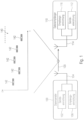
- Fig. 1 shows a schematic block diagram of a system with a data transmitter 100 and a data receiver 110, according to an exemplary embodiment of the present invention.
- the data transmitter 100 is designed to send data 120 using a hopping pattern.
- the data receiver 110 is designed to receive data 120 from the data transmitter 100 using a hopping pattern.
- the hop pattern 140 may have a plurality of hops 142 that are distributed in time and/or frequency.
- the data transmitter 100 can be designed to send data 120 distributed in time and/or frequency according to the hop pattern 140.
- the data receiver 110 can be designed to receive data 120 that is distributed in time and/or frequency according to the hop pattern 140.
- the data transmitter 100 may have a transmission device (or transmission module, or transmitter) 102, which is designed to send the data 120.
- the transmitting device 102 can be connected to an antenna 104 of the data transmitter 100 be connected.
- the data transmitter 100 can also have a receiving device (or receiving module, or receiver) 106, which is designed to receive data.
- the receiving device 106 can be connected to the antenna 104 or another (separate) antenna of the data transmitter 100.
- the data transmitter 100 can also have a combined transceiver device.
- the data receiver 110 can have a receiving device (or receiving module, or receiver) 116, which is designed to receive data 120.
- the receiving device 116 can be connected to an antenna 114 of the data receiver 110.
- the data receiver 110 can have a transmitting device (or transmitting module, or transmitter) 112, which is designed to transmit data.
- the transmitting device 112 can be connected to the antenna 114 or another (separate) antenna of the data receiver 110.
- the data receiver 110 can also have a combined transceiver.
- data transmitter 100 may be a sensor node, while data receiver 110 may be a base station.
- a communication system includes at least one data receiver 110 (base station) and a plurality of data transmitters (sensor nodes, such as heating meters).
- the data transmitter 100 is a base station while the data receiver 110 is a sensor node.
- both the data transmitter 100 and the data receiver 110 are sensor nodes.
- both the data transmitter 100 and the data receiver 110 are base stations.
- the data transmitter 100 and the data receiver 110 can optionally be designed to send or receive data 120 using the telegram splitting method.
- a telegram or data packet 120 is divided into a plurality of sub-data packets (or sub-data packets, or sub-packets) 142 and the sub-data packets 142 are distributed in time and/or in frequency according to the jump pattern 140 from the data transmitter 100 transmitted to the data receiver 110, whereby the data receiver 110 reassembles (or combines) the sub-data packets to obtain the data packet 120.
- Each of the sub-data packets 142 contains only a part of the data packet 120.
- the data packet 120 can also be channel coded, so that not all sub-data packets 142 but only a part of the sub-data packets 142 are required for error-free decoding of the data packet 120.
- the temporal distribution of the plurality of sub-data packets 142 can, as already mentioned, take place according to a time and/or frequency hopping pattern.
- a time jump pattern can specify a sequence of transmission times or transmission time intervals at which the sub-data packets are sent. For example, a first sub-data packet can be sent at a first transmission time (or in a first transmission time slot) and a second sub-data packet at a second transmission time (or in a second transmission time slot), the first transmission time and the second transmission time being different.
- the time jump pattern can define (or specify, or indicate) the first transmission time and the second transmission time.
- the time jump pattern can indicate the first transmission time and a time interval between the first transmission time and the second transmission time.
- the time jump pattern can also only indicate the time interval between the first time and the second transmission time. Between the sub-data packets there may be transmission pauses during which no transmission takes place.
- the sub-data packets can also overlap (overlap) in time.
- a frequency hopping pattern can specify a sequence of transmission frequencies or transmission frequency hops with which the sub-data packets are sent. For example, a first sub-data packet can be sent with a first transmission frequency (or in a first frequency channel) and a second sub-data packet with a second transmission frequency (or in a second frequency channel), the first transmission frequency and the second transmission frequency being different.
- the frequency hopping pattern can define (or specify, or indicate) the first transmission frequency and the second transmission frequency.
- the frequency hopping pattern may indicate the first transmission frequency and a frequency spacing (transmission frequency hop) between the first transmission frequency and the second transmission frequency.
- the frequency hopping pattern can also only indicate the frequency distance (transmission frequency hop) between the first transmission frequency and the second transmission frequency.
- the plurality of sub-data packets 142 can also be transmitted from the data transmitter 100 to the data receiver 110 in a distributed manner in both time and frequency.
- the distribution of the plurality of sub-data packets in time and frequency can take place according to a time and frequency hopping pattern.
- a time and frequency hopping pattern can be the combination of a time hopping pattern and a frequency hopping pattern, ie a sequence of transmission times or transmission time intervals with which the sub-data packets are transmitted, whereby the Transmission times (or transmission time intervals) are assigned to transmission frequencies (or transmission frequency jumps).
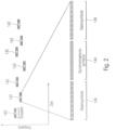
- Fig. 2 shows in a diagram an occupancy of the transmission channel when transmitting a plurality of sub-data packets 142 according to a time and frequency hopping pattern.
- the ordinate describes the frequency and the abscissa describes the time.
- a synchronization sequence 144 can also be divided into the plurality of sub-data packets 142, so that the plurality of sub-data packets 142 in addition to data (data symbols in Fig. 2 ) 146 each part of the synchronization sequence (synchronization symbols in Fig. 2 ) 144 included.
- Data transmitter 100 shown can be expanded to include a repeat transmission mode in which data transmitter 100 transmits data 120 using a first hopping pattern and repeatedly (ie, again) using a second hopping pattern.
- the data transmitter 100 can be operated both in repeat transmission mode and in a single transmission mode, ie as described above. Of course, the data transmitter 100 can also be operated in both modes.
- the one described above and for example in Fig. 1 data receiver 110 shown can be expanded to include a repeat transmission mode in which the data receiver 110 receives the data 120 using a first hopping pattern and repeatedly (ie again) using a second hopping pattern.
- the data receiver 110 can be operated both in repeat transmission mode and in a single transmission mode, ie as described above. Of course, the data receiver 110 can also be operated in both modes.
- the following description primarily deals with the repeat transmission mode, with reference being made to the above description for the single transmission mode. Furthermore, it should be noted that the aspects of the single broadcast mode described above are also applicable to the repeat broadcast mode.
- Fig. 3 shows a schematic block diagram of a system with a data transmitter 100 and a data receiver 110, according to an exemplary embodiment of the present invention.
- the data receiver 110 is configured to repeatedly receive data 120 in a first mode using a first hopping pattern 140_1 and a second hopping pattern 140_2. Furthermore, the data receiver 110 is designed to receive data 120 in a second mode simply (ie once or not repeatedly) using a third hop pattern 142 (cf. Fig. 1 ), where the jump patterns of the first mode and the second mode are different.
- the data receiver 110 can be designed to recognize a repeated transmission of data based on the first hop pattern 140_1 and/or the second hop pattern 140_2, and to recognize a simple transmission of data based on the third hop pattern.
- the data receiver can be designed to detect one of the two hop patterns (e.g. the first hop pattern) in a receive data stream in order to receive the data transmitted with the one hop pattern, wherein the data receiver can be designed to detect the other hop pattern (e.g. second Jump pattern) in the received data stream using the already detected jump pattern (eg first jump pattern) to receive the data transmitted with the other jump pattern (eg second jump pattern).
- the detection and synchronization e.g. time and frequency estimation
- the detection can, for example, be designed in such a way that it detects almost all jump patterns (e.g.
- the data receiver 110 can search for the jump patterns 140_1 and 140_2, whereby it should find at least one of the two jump patterns 140_1 and 140_2. Then the data receiver 110 can decode this hopping pattern and determine whether it is error-free. If it is not error-free, then the data receiver 110 can search for the other hop pattern, whereby the data receiver 110 does not know whether the previously found hop pattern was the first or second transmission (the first hop pattern 140_1 or second hop pattern 140_2). Since this was more difficult to find, individual decoding is unlikely to help here.
- MRC maximum ratio combining
- the first jump pattern 140_1 and the second jump pattern 140_2 can be selected from a first set of jump patterns, while the third jump pattern can be selected from a second set of jump patterns.
- the first set of skipping patterns and the second set of skipping patterns may be different.
- the data transmitter 100 may select the first hop pattern 142_1 and the second hop pattern 142_2 from the first class of hop patterns (e.g. from the eight hop patterns listed in Section 3.3) while a another data transmitter for the transmission of data in the second mode can select a hop pattern from the second class of hop patterns (e.g. from the eight hop patterns listed in Section 3.2). Since the first class of hop patterns and the second class of hop patterns are different, it can be ensured that even if data is transmitted at the same time or at least overlapping in time Data transmitter and the other data transmitter a collision probability can be kept as low as possible.
- the first hop pattern 140_1 and the second hop pattern 140_2 can be selected from a third set of hop patterns both in the first mode and also in the second mode.
- the third set of skip patterns may be a subset of, or different from, the first set of skip patterns or the second set of skip patterns.
- the first jump pattern 140_1 and the second jump pattern 140_2 can be shifted from one another in at least one of the frequency and the time, so that the first jump pattern 142_0 and the second jump pattern 142_0 are at least partially interleaved.
- both the first hop pattern 140_1 and the second hop pattern 140_2 may have hops 142 that are distributed in time and/or frequency, such that the jumps 142 of a hop pattern are spaced apart in time and/or frequency, the first hop pattern 140_1 and the second jump pattern 140_2 can be shifted relative to one another in time and/or frequency such that at least some of the jumps 142 of the second jump pattern 140_2 are arranged between at least some of the jumps 142 of the first jump pattern 140_1.
- the jumps 142 of the first jump pattern 140_1 and the jumps 142 of the second jump pattern 140_1 may be arranged alternately in time.
- the first jump pattern 140_1 and the second jump pattern 140_2 can be different.
- jumps 142 of the first jump pattern 140_1 and jumps 142 of the second jump pattern 140_2 can be distributed differently in time and/or frequency.
- two consecutive jumps (e.g. first jump and second jump) of the first jump pattern 140_1 may have a different time interval and/or frequency interval than two consecutive jumps (e.g. first jump and second jump) of the second jump pattern 140_2.
- the second hopping pattern 140_2 can be a frequency and/or time-shifted version of the first hopping pattern 140_1.
- the first jump pattern 140_1 and the second jump pattern 140_2 can be the same and only shifted in time and/or frequency.
- jumps 142 of the first Jump pattern 140_1 and jumps 142 of the second jump pattern 140_2 have the same relative time interval and frequency interval.
- the data transmitter 100 can be designed to transmit the first hopping pattern 140_1 and the second hopping pattern 140_2 in only partially overlapping or different frequency bands.
- the data transmitter 100 may be configured to randomly transmit the first hopping pattern 140_1 or the second hopping pattern 140_2 in one of at least two different frequency bands, and to transmit the other hopping pattern in the other frequency band.
- the data transmitter 100 can be designed to determine a time offset and/or a frequency offset between the first hop pattern 140_1 and the second hop pattern 140_2 depending on an operating parameter of the data transmitter 100.
- the operating parameter of the data transmitter 100 can either be known to the data receiver 110 or the data receiver 110 is designed to determine the operating parameter, for example to estimate it or to calculate it using a hypothesis test.
- the data receiver 110 can be designed to try out all possible time offsets until the correct time offset is found.
- the data receiver 110 can be designed to try out all possible frequency offsets until the correct frequency offset is found.
- the operating parameter of the data transmitter 100 can be an inherent parameter of the data transmitter itself, such as addressing information, identification information, a quartz tolerance, a frequency offset or an available transmission energy.
- the operating parameter of the data transmitter 100 may be a parameter assigned to the data transmitter 100, such as an assigned frequency offset, an assigned time offset, a radio cell, a geographical position, a system time or a priority of the data transmitter or the data.
- the operating parameter of the data transmitter 100 can be at least part of user data or error protection data.
- the operating parameter of the data transmitter 100 can be a random frequency offset or a random time offset.
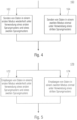
- Fig. 4 shows a flowchart of a method 160 for sending data, according to an exemplary embodiment.
- the method 160 includes a step 162 of sending data in a first mode repeatedly using a first hopping pattern and a second hopping pattern. Further, the method 160 includes a step 164 of sending data in a second mode once using a third hopping pattern, where the hopping patterns of the first mode and the second mode are different.
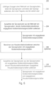
- Fig. 5 shows a flowchart of a method 170 for receiving data, according to an exemplary embodiment.
- the method 170 includes a step 172 of receiving data in a first mode repeatedly using a first hopping pattern and a second hopping pattern. Further, the method 170 includes a step 174 of receiving data in a second mode once using a third hopping pattern, where the hopping patterns of the first mode and the second mode are different.
- Fig. 6 a method for generating hopping patterns for a simple (ie one-time) transmission of data using a hopping pattern
- Fig. 7 shows a method for generating hopping patterns for repeated transmission of data using two hopping patterns.
- Fig. 6 shows a flowchart of a method 200 for generating a set of jump patterns, according to an exemplary embodiment.
- the method 200 includes a step 202 of randomly generating a plurality of hop patterns, the hop patterns having at least two hops that are distributed in frequency and time.
- the method 200 further includes a step 204 of selecting the jump patterns from the plurality of jump patterns whose autocorrelation functions have predetermined autocorrelation properties in order to obtain jump patterns with predetermined autocorrelation properties.
- those jump patterns whose autocorrelation function secondary maxima have one can fulfill the predetermined autocorrelation properties do not exceed the specified minimum amplitude threshold.
- the amplitude threshold can, for example, be equal to a number of jumps of a cluster of a plurality of clusters into which the jump pattern is divided.
- a cluster can, for example, be a number of hops that have the same time and/or frequency spacing from one another.
- those jump patterns can fulfill the predetermined autocorrelation properties, the partial sum of which, formed over a predetermined number of largest amplitude values of the respective autocorrelation function, is smaller than a predetermined threshold value.
- the threshold value can be chosen so that at least two jump patterns (or a predetermined number of jump patterns) meet the predetermined autocorrelation properties.
- the method 200 may further comprise a step 206 of calculating cross-correlation functions between the jump patterns with predetermined autocorrelation properties. Furthermore, the method 200 may include a step 208 of selecting the jump patterns from the jump patterns with predetermined autocorrelation properties, whose cross-correlation functions have predetermined cross-correlation properties, in order to obtain jump patterns with predetermined autocorrelation properties and predetermined cross-correlation properties.
- those jump patterns whose partial sums, formed over a predetermined number of largest amplitude values of the respective cross-correlation function, are the smallest can fulfill the predetermined cross-correlation properties.
- Fig. 7 shows a flowchart of a method 210 for generating a first set of skip patterns and a second set of skip patterns.
- the method 210 includes a step 212 of randomly generating a plurality of hop patterns for the first set of hop patterns and a plurality of hop patterns for the second set of hop patterns, the hop patterns having at least two hops distributed in frequency and time, where the jump patterns for the first set of jump patterns and the jump patterns for the second set of jump patterns are different.
- the method 210 includes a step 214 of selecting the jump patterns from the plurality of jump patterns for the first set of jump patterns, the autocorrelation functions of which are predetermined Have autocorrelation properties in order to obtain jump patterns with predetermined autocorrelation properties for the first set of jump patterns, and selecting the jump patterns from the plurality of jump patterns for the second set of jump patterns whose autocorrelation functions have predetermined autocorrelation properties in order to obtain jump patterns with predetermined autocorrelation properties for the second set of jump patterns to obtain.
- a time interval between the jumps of the jump patterns for the second set of jump patterns can be at least as long as a time length of one of the jumps of the jump patterns for the first set of jump patterns.
- the shortest time interval between two sub-data packets can be maximized. This would be (T_Frame - N*T_Burst)/(N-1), i.e. an equidistant temporal distribution of the bursts (within the clusters and between the clusters). Since this regularity is of course not optimal for the design process, a slight jitter can be introduced.
- those jump patterns whose autocorrelation function secondary maxima do not exceed a predetermined minimum amplitude threshold can fulfill the predetermined autocorrelation properties.
- the amplitude threshold can, for example, be equal to a number of jumps of a cluster of a plurality of clusters into which the jump pattern is divided.
- a cluster can, for example, be a number of hops that have the same time and/or frequency spacing from one another.
- those jump patterns can fulfill the predetermined autocorrelation properties, the partial sum of which, formed over a predetermined number of largest amplitude values of the respective autocorrelation function, is smaller than a predetermined threshold value.
- the threshold value can be chosen so that at least two jump patterns (or a predetermined number of jump patterns) meet the predetermined autocorrelation properties.
- the method 210 may further include a step 216 of calculating cross-correlation functions between the jump patterns with predetermined autocorrelation properties for the first set of jump patterns and cross-correlation functions between the jump patterns with predetermined ones Have autocorrelation properties for the second set of jump patterns.
- the method may include a step 218 of selecting the jump patterns from the jump patterns with predetermined autocorrelation properties for the first set of jump patterns, the cross-correlation functions of which have predetermined cross-correlation properties, to obtain jump patterns with predetermined autocorrelation properties and predetermined cross-correlation properties for the first set of jump patterns, and the jump patterns from the jump patterns with predetermined autocorrelation properties for the second set of jump patterns, the cross-correlation functions of which have predetermined cross-correlation properties, in order to obtain jump patterns with predetermined autocorrelation properties and predetermined cross-correlation properties for the second set of jump patterns.
- those jump patterns whose partial sums, formed over a predetermined number of largest amplitude values of the respective cross-correlation function, are the smallest can fulfill the predetermined cross-correlation properties.
- Jump patterns that come with the in Fig. 6 or Fig. 7 The method shown can be used, for example, in a system for unidirectional or bidirectional data transmission from many sensor nodes to a base station using the so-called “Telegram Splitting Multiple Access (TSMA)" access method.
- TSMA Transmission Splitting Multiple Access
- TSMA TSMA
- the bursts 142 can be distributed according to a real or pseudo-random principle both over time and over the available frequencies.
- This approach to telegram splitting provides particularly high robustness against interference from other sensor nodes, regardless of whether they come from your own or third-party systems.
- the interference robustness of the own sensor nodes is achieved in particular by distributing the various user signal bursts as evenly as possible over both the time and frequency ranges.
- This random distribution can be achieved through various measures, such as (1) through unavoidable tolerance deviations of the crystal reference oscillator with regard to the frequency, (2) through the random asynchronous channel access, any granularity in the time domain occurs, and (3) through different burst arrangements different sensor nodes to different hopping patterns.
- the sub-data packets can be sent at least twice at different times, for example in hop patterns that are as different as possible and in frequency bands that are as different as possible. Since only one transmitter in the sensor node is available for transmitting the signal, certain restrictions result for the interleaved repetition with regard to the temporal burst arrangement in the hop pattern. The way in which the first and second transmissions are interleaved in the event of a repetition will be explained in more detail later.
- the diversely redundant signals can be combined at the receiving end in all possible forms, such as maximum ratio combining (MRC), equal gain combining, scanning/switching combining or selection combining.
- MRC maximum ratio combining
- equal gain combining scanning/switching combining
- selection combining selection combining
- a data packet 120 (hereinafter also referred to as a frame), as in Fig. 8a shown, distributed both over time and over frequencies.
- Fig. 8a Shows in detail Fig. 8a in a diagram a structure of a frame 120 with a TSMA hop pattern 140.
- the ordinate describes the frequency or channels (frequency channels) and the abscissa describes the time.
- the start time T 0 of a frame 120 with the total duration T frame is randomly selected by the sensor node 100 due to the asynchronous transmission.
- the duration T burst of a burst 142 can vary and is described below without limiting its generality assumed to be constant, whereas the time intervals t n , (n + 1) , which each characterize the distance between two neighboring burst centers (here the two bursts with the indices n and n+1 ), are each random variables, all within a predeterminable range T A_min ⁇ t n,(n+1) ⁇ T A_max for n ⁇ ⁇ 1,2,...,N-1 ⁇ .
- N is the number of bursts 142 within a frame 120.
- the frequencies used for transmission are assumed to be in the form of discrete frequency channels, which lie in a predetermined frequency channel grid.
- the frequency separation f n,(n+1) between 2 bursts 142 is a multiple of the carrier spacing B C used in TSMA and is therefore independent of the symbol rate S R used. ( S R ⁇ B C ).
- the relative starting frequency of a frame is denoted by f 0 .
- the number of available frequency channels is given as L and N ⁇ L. In this respect, there are usually more or exactly as many frequency channels as are required by the N bursts 142 and within a frame 120 each of the N bursts 142 is located in one other frequency channel.
- the frequencies used by the N bursts do not have to be contiguous, but can be distributed arbitrarily within the L frequencies present.
- the arrangement of the N bursts 142 in time and frequency is referred to below as the TSMA pattern (TSMA jump pattern). If this jump pattern is known to the receiver, it can synchronize with it based on the pilot sequences contained in some or every burst 142 and then decode the received data.
- TSMA jump pattern TSMA jump pattern
- alternating interleaving is recommended, where the bursts of the first and second transmission alternate.
- the new jump patterns for repeatedly transmitted data can optionally match the jump patterns for simply transmitted data, i.e. have the lowest possible cross-correlation.
- the TSMA hopping patterns should be robust a) against external interference from other systems (here neither the bandwidth nor the duration of the interference is known) as well as b) against interference from your own system.
- c) it can be made as easy as possible for the recipient to distinguish between shipments with and without repetition, especially when using maximum ratio combining.
- Aspects a) and c) are independent of the design process and can be defined in advance. Improved or even maximum immunity to external interference can be achieved, for example, by placing the two frames to be repeated in two different frequency bands (with their respective L frequency channels). The greater the frequency spacing (see Fig. 8b ), the lower the probability that an external interferer can disrupt both frames at the same time. Shows in detail Fig.
- Fig. 8b in a diagram an occupancy of two frequency channels 150_1 and 150_2 during the repeated transmission of data using a first hop pattern 140_1 and a second hop pattern 140_2.
- the ordinate describes the frequency and the abscissa describes the time.
- Fig. 8b shows an interleaved frame transmission with repetition using two different frequency bands.
- the receiver can, for example, use the hopping pattern to distinguish between transmissions with and without repetition if different hopping patterns are used for both forms of transmission.
- the hopping patterns shown in Section 3.2 may be used, and for non-repetition transmissions, for example, the hopping patterns shown in Section 3.3 may be used.
- a different (new) hopping pattern can be used for the first transmission in repeat mode than for the second transmission.
- the use of a single hopping pattern is sufficient for all transmissions in repeat mode. This measure also makes it easier for the receiver to recognize the individual bursts together with the same pattern in repeat mode.
- jump patterns are used for the individual transmission (e.g. the jump patterns from Section 3.2) than those used for the first and second transmission in the event of a repetition (e.g. the jump patterns from Section 3.2), a complete interference with the jump patterns in the event of a repetition (the Overlapping of all N bursts of a frame) is not possible.
- the cross-correlated data show that in the worst case a maximum of C bursts (of a cluster) can meet.
- the average number of hits can be reduced again.
- the following examines the interference immunity of transmitters that use the same hopping pattern in repeat mode. If two transmitters with identical hopping patterns were to be transmitted at the same time T 0 (see Fig. 8b ) start in the same frequency band, then without any countermeasures there would be a complete overlap of all 2N bursts in both frames of the repeat mode. Such a situation can be almost completely prevented by parameter variation. For example, diversity can be achieved by introducing a variable, multi-stage time offset T W (see Figure 2), or randomly starting the first burst in one of the two frequency bands A or B.
- the TSMA pattern can also be subjected to, for example, a random positive or negative frequency offset (e.g. in multiples of the carrier distance BC ).
- a random positive or negative frequency offset e.g. in multiples of the carrier distance BC .
- Fig. 9 Shows in detail Fig. 9 in a diagram a schematic view of a structure of a TSMA hop pattern 142.
- the ordinate describes the frequency in frequency channels and the abscissa describes the time.
- Fig. 9 shows a structure of the TSMA hopping pattern 142 with cluster arrangement and frequency occupancy.
- the 3 bursts in the 8 clusters can each have the same frequency spacing relative to each other, at least 8 additional frequency bands can be reserved, leaving a maximum of 28 frequency bands for the basic assignment of the 3 bursts. For example, any relative assignment can be made with 3 different frequency bands.
- the largest possible frequency swing for neighboring bursts as is the case with the base assignments (1,28,14) or (1,24,12), proves to be advantageous with regard to later optimizations.
- the assignment of the individual clusters to one another can also be done randomly.
- the order of the numbers ⁇ 1,2,3,4,5,6,7,8 ⁇ can be permuted with each other arbitrarily (Matlab command: randperm(8)) and this 8 Different values can each be added to the base assignment to obtain the frequency assignment of the bursts in the 8 clusters.
- a permutation of 12 starting values (Matlab command: randperm(12)) is even possible and the first 8 values can be reconfigured with the corresponding Base assignment (1,24,12) can be added. If two groups of jump patterns are to be designed, for example two groups of 8 jump patterns with and without repetition, then it is recommended to use two basic arrangements with different frequency swings. Then no entire clusters can collide between the groups.
- the message is split into many small bursts 142 in both the time and frequency directions according to the hopping pattern 140. Due to the asynchronous transmission and the different frequency offsets of the individual sensor nodes 100, the bursts 142 are smeared both over time and over the available frequency spectrum. If all sensor nodes 100 have the same hopping pattern, then as the number of participants increases, bursts from different participants overlap each other in time (in the worst case completely) and thus interfere with each other. The more bursts 142 within a frame 120 are disturbed by bursts from other participants, the greater the probability that the error correction on the receiver side will fail and transmission errors will occur.
- TSMA Transmission Splitting Multiple Access
- Embodiments create a set of hopping patterns that ideally minimize the packet error rate (Frame or Packet Error Rate, FER, PER) of the radio transmission system. This is done under the assumption that all radio subscribers have the same set use jump patterns. While only a finite (although usually relatively large) number of permutations is possible with regard to the arrangement of the radio frequencies in a hopping pattern by introducing discrete radio channels, the temporal arrangement of the bursts 142 leads to an extremely large number of permutation possibilities due to a continuous time axis, ie Jump patterns. This means that a “full search” across all possible jump patterns is almost impossible.
- the packet error rate Frazier or Packet Error Rate, FER, PER
- the method on which the invention is based is therefore based on a Monte Carlo approach, which selects a set with the best properties in terms of an expected minimum error rate from a very large number of (pseudo-) randomly generated jump patterns using suitable design criteria.
- the number of jump patterns in this set is P selection .
- a metric is required which ideally has a strictly monotonic relationship with the expected packet error rate, and whose minimization ideally minimizes the packet error rate.
- the two-dimensional (2D) autocorrelated or cross-correlated of the jump pattern can be considered as a design criterion.
- the frequency index f in the AKF extends from -2S to + 2S.
- the time index t runs from -T frame to T frame , in steps of T frame / T A.
- the AKF dimension of ⁇ x,x is therefore (4S+1) ⁇ (2M + 1).
- the influence of adjacent channel interference can also be taken into account in the time and frequency information matrix X. This is important if the reception filters in the receiver 110 do not have any particular selectivity (selectivity) with regard to adjacent channel interference.
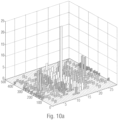
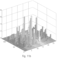
- Fig. 10a and 10b show two AKF examples.
- the lower this threshold is, the fewer bursts are disturbed in a frame and the probability of a transmission error decreases.
- Fig. 10b shows a less favorable jump pattern in which the threshold value is clearly exceeded in some places. This increases the likelihood of transmission errors.
- P optimal candidates of the jump patterns can therefore be generated whose AKF secondary maxima do not exceed a predetermined minimum amplitude threshold N threshold ⁇ C ( C is the cluster size).
- N threshold ⁇ C is the cluster size.
- the generation of candidate jump patterns takes place as part of a Monte Carlo simulation, in which jump patterns with random time and frequency patterns (within the framework of the mentioned boundary conditions, see above) are generated. If N threshold > C applies to the threshold value, the number of values that exceed the value C should be as small as possible.
- the (4S+1) ⁇ (2M+1) elements of the 2D autocorrelated ⁇ x,x can be sorted in ascending order in a vector V Sort . Since the total sum across all AKF elements is always approximately constant for all jump patterns and most AKF elements have values of 0, 1 or C (complete cluster collision). only, if available, the values greater than C. In this respect, it is sufficient that only the last v AKF elements of V Sort i.e. V Sort (end- v AKF + 1:end) are considered.
- the first design step can be repeated with a new set of parameters. For example, there may be a desire to generate multiple sets of jump patterns with different oscillator deviations and optimize them together. Different oscillator deviations cause different security strips S, which changes the degree of freedom of the possible burst assignment. In this respect, some parameters within the AKF calculation also change. Or a new jump pattern set should be generated that enables multiple repetitions using a multi-stage time offset T W. The requirements for timing change here. If a burst-by-burst alternating interleaving of the jump patterns is provided, the shortest distance between two original bursts of a jump pattern can be determined and specified, which then determines the time offset T W. The time offset T W should be chosen to be significantly larger than the minimum time T A_min .
- the first design step finding P 1 optimal candidates of a set of jump pattern patterns, is completely independent of finding P 2 optimal candidates of another pattern set.
- all parameter specifications for the patterns clusters, frequency patterns, time intervals, etc.
- the design parameters N threshold , V sort , number of rows and columns of the 2D AKF ⁇ x , x , etc.
- N threshold , V sort number of rows and columns of the 2D AKF ⁇ x , x , etc.
- the time index of ⁇ x,y runs unchanged in steps of T frame / T A from - T frame to T frame.
- the KKF frequency index f generally extends from -(S x + S y ) to + (S x + S y ) , since the two jump patterns under consideration can have different deviations in their frequency error behavior (oscillator frequency deviations).
- Fig. 11a and 11b again show two 2D KKF examples, a favorable case ( Fig. 11a ) and an unfavorable case ( Fig. 11b ).
- the P selection of different jump patterns 142 is to be searched for, which have the most favorable 2D KKF properties, since these correlate with a comparatively low maximum number of colliding bursts in a frame.
- the properties of (( P selection -1) ⁇ P selection )/2 different 2D KKF can be evaluated based on the stored sums SUM KKF in the matrix O vKKF .
- Those P selection of different jump patterns whose total sum results in a minimum over the (( P selection -1) ⁇ P selection )/2 different partial sums SUM KKF from O vKKF result in the optimal P selection jump patterns.
- P selection ⁇ P optimal is the aim, there are various possible combinations according to the binomial coefficient "P optimal over P selection ", a range that can usually no longer be fully processed.
- FIG. 12 Shows in detail Fig. 12 a flowchart of a method 260 for generating jump patterns, according to an exemplary embodiment.
- a first step 262 the method 260 is started.
- n is set equal to one, where n is a running variable.
- a jump pattern can be randomly generated.
- the above-mentioned degrees of freedom with regard to the frequency channel occupancy such as a frequency channel assignment of the bursts with a basic assignment of the bursts within the cluster and an assignment of the clusters to one another, can be taken into account.
- the above-mentioned degrees of freedom regarding the time intervals such as a determination of the time intervals within the cluster and between the clusters, can be taken into account.
- the autocorrelation function of the randomly generated jump pattern can be calculated.
- a 2D AKF calculation ⁇ x,x (f,t) can be done.
- the 2D AKF values can be sorted in a vector v Sort .
- SUM AKF sum( v Sort (end-v AKF +1:end)).
- a fifth step 270 it can be determined whether the randomly generated jump pattern has the specified autocorrelation properties. For example, it can be determined whether the AKF secondary maxima of the jump pattern do not exceed a predetermined minimum amplitude threshold N threshold ⁇ C ( C is the cluster size). In detail, it can be determined whether the sum SUM AKF of these v AKF elements (partial sum) does not exceed the sum threshold value of S Sum_AKF_Threshold of, for example , (v AKF -1) ⁇ C + N.
- the third step is repeated. If the jump pattern has the specified autocorrelation properties, then the process continues.
- a seventh step 274 it can be checked whether an optimal number P Optimal of jump patterns is available.
- step 276 it is determined whether a new set of jump patterns should be generated. If so, then the second step 264 is repeated. If not, then the process continues. Furthermore, it can be determined whether a further set of jump patterns should optionally be generated for a different parameter set, such as a different oscillator offset or a different cluster appearance with changed time intervals or frequency jumps.
- a ninth step 278, the cross-correlation functions between the jump patterns with predetermined autocorrelation properties are calculated.
- n can be set equal to one and GS threshold can be set to a large threshold, such as 10 6 .
- P 1 selection jump patterns are newly and randomly selected from the P 1 optimally existing first jump patterns and P 2 selection jump patterns are newly and randomly selected from the P 2 optimally existing second jump patterns.
- P 1 Optimal different numbers are rolled out in a random order
- F 1 randperm(1: P 1 Optimal )
- P 2 Optimal different numbers are rolled out in a random order
- F 2 randperm(1: P 2 Optimal ).
- the first P 1 selection can be selected
- Pattern1 selection F(1: P 1 selection )
- the first P 2 selection can be selected from it
- Pattern2 selection F(1: P 2 selection ).
- the selected jump pattern can be saved.
- a time hopping pattern, a frequency hopping pattern, or a combination of a time hopping pattern and the frequency hopping pattern may be used for the individual transmission of data using a hopping pattern.
- the time jump pattern can be one of the eight time jump patterns, each with 24 jumps, listed in the following table:
- each row is a time jump pattern, with each column in the table being a jump of the respective time jump pattern starting from a second jump, so that each time jump pattern has 24 jumps, with each cell in the table having a time distance from a reference point of the respective jump a same reference point of an immediately following jump in - preferably multiples of - symbol durations.
- the frequency hopping pattern can be one of the eight frequency hopping patterns, each with 24 hops, listed in the following table:
- each row is a frequency hopping pattern
- each column is a hop of the respective frequency hopping pattern
- each cell indicates a transmission frequency of the respective hop of the respective frequency hopping pattern in carriers from UCG_C0 to UCG_23.
- the respective time hopping pattern and the respective frequency hopping pattern can have the same line number in the respective table.
- a time hopping pattern, a frequency hopping pattern or a combination of a time hopping pattern and the frequency hopping pattern can be used for the repeated transmission of data using two hopping patterns (e.g. first hopping pattern and second hopping pattern).
- the time jump pattern can be one of the eight time jump patterns, each with 24 jumps, listed in the following table:
- each row is a time jump pattern, with each column in the table being a jump of the respective time jump pattern starting from a second jump, so that each time jump pattern has 24 jumps, with each cell in the table having a time distance from a reference point of the respective jump a same reference point of an immediately following jump in - preferably multiples of - symbol durations.
- the frequency hopping pattern can be one of the eight frequency hopping patterns, each with 24 hops, listed in the following table:
- each row is a frequency hopping pattern
- each column is a hop of the respective frequency hopping pattern
- each cell indicates a transmission frequency of the respective hop of the respective frequency hopping pattern in carriers from UCG_C0 to UCG_23.
- the respective time hopping pattern and the respective frequency hopping pattern can have the same line number in the respective table.
- aspects have been described in connection with a device, it is understood that these aspects also represent a description of the corresponding method, so that a block or a component of a device is also to be understood as a corresponding method step or as a feature of a method step. Similarly, aspects described in connection with or as a method step also represent a description of a corresponding block or detail or feature of a corresponding device.
- Some or all of the method steps may be performed by a hardware apparatus (or using a hardware device). Apparatus), such as a microprocessor, a programmable computer or an electronic circuit. In some embodiments, some or more of the key process steps may be performed by such apparatus.
- embodiments of the invention may be implemented in hardware or in software.
- the implementation may be using a digital storage medium such as a floppy disk, a DVD, a Blu-ray Disc, a CD, a ROM, a PROM, an EPROM, an EEPROM or a FLASH memory, a hard drive or other magnetic or optical memory are carried out on which electronically readable control signals are stored, which can interact or interact with a programmable computer system in such a way that the respective method is carried out. Therefore, the digital storage medium can be computer readable.
- Some embodiments according to the invention thus include a data carrier that has electronically readable control signals that are capable of interacting with a programmable computer system such that one of the methods described herein is carried out.
- embodiments of the present invention can be implemented as a computer program product with a program code, wherein the Program code is effective to perform one of the methods when the computer program product runs on a computer.
- the program code can, for example, also be stored on a machine-readable medium.
- inventions include the computer program for performing one of the methods described herein, wherein the computer program is stored on a machine-readable medium.
- an exemplary embodiment of the method according to the invention is therefore a computer program that has a program code for carrying out one of the methods described herein when the computer program runs on a computer.
- a further exemplary embodiment of the method according to the invention is therefore a data carrier (or a digital storage medium or a computer-readable medium) on which the computer program for carrying out one of the methods described herein is recorded.
- the data carrier, digital storage medium or computer-readable medium is typically tangible and/or non-perishable.
- a further exemplary embodiment of the method according to the invention is therefore a data stream or a sequence of signals which represents the computer program for carrying out one of the methods described herein.
- the data stream or the sequence of signals can, for example, be configured to be transferred via a data communication connection, for example via the Internet.
- Another embodiment includes a processing device, such as a computer or a programmable logic device, configured or adapted to perform one of the methods described herein.
- a processing device such as a computer or a programmable logic device, configured or adapted to perform one of the methods described herein.
- Another embodiment includes a computer on which the computer program for performing one of the methods described herein is installed.
- a further embodiment according to the invention includes a device or system designed to transmit a computer program to a receiver for carrying out at least one of the methods described herein.
- the transmission can take place electronically or optically, for example.
- the recipient may be, for example, a computer, a mobile device, a storage device or a similar device.
- the device or system can, for example, comprise a file server for transmitting the computer program to the recipient.
- a programmable logic device e.g., a field programmable gate array, an FPGA
- a field programmable gate array may cooperate with a microprocessor to perform any of the methods described herein.
- the methods are performed by any hardware device. This can be universally applicable hardware such as a computer processor (CPU) or hardware specific to the method, such as an ASIC.
- the devices described herein may be implemented, for example, using a hardware apparatus, or using a computer, or using a combination of a hardware apparatus and a computer.
- the devices described herein, or any components of the devices described herein may be at least partially implemented in hardware and/or in software (computer program).
- the methods described herein may be implemented, for example, using a hardware apparatus, or using a computer, or using a combination of a hardware apparatus and a computer.
Landscapes
- Engineering & Computer Science (AREA)
- Signal Processing (AREA)
- Computer Networks & Wireless Communication (AREA)
- Mobile Radio Communication Systems (AREA)
- Dc Digital Transmission (AREA)
Claims (8)
- Transmission de données, par un transmetteur de données (100), à l'aide d'un premier modèle de saut et d'un deuxième modèle de saut;dans laquelle les données sont transmises à l'aide du premier modèle de saut et dans laquelle les données sont transmises de manière répétée à l'aide du deuxième modèle de saut;dans laquelle les données sont transmises divisées en une pluralité de sous-paquets de données selon le premier modèle de saut, de sorte que soit transmis, à chaque saut du premier modèle de saut, un sous-paquet de données de la pluralité de sous-paquets de données,dans laquelle les données sont transmises divisées en une pluralité de sous-paquets de données selon le deuxième modèle de saut, de sorte que soit transmis, à chaque saut du deuxième modèle de saut, un sous-paquet de données de la pluralité de sous-paquets de données,dans laquelle le premier modèle de saut et le deuxième modèle de saut sont, chacun, un modèle de saut dans le temps, un modèle de saut en fréquence, ou une combinaison du modèle de saut dans le temps et du modèle de saut en fréquence;dans laquelle le modèle de saut dans le temps est l'un parmi les huit modèles de saut dans le temps avec, chacun, 24 sauts mentionnés dans le tableau suivant:
 dans laquelle, dans le tableau, chaque ligne est un modèle de saut dans le temps, dans laquelle, dans le tableau, chaque colonne est un saut du modèle de saut dans le temps respectif en commençant à partir d'un deuxième saut, de sorte que chaque modèle de saut dans le temps présente 24 sauts, dans laquelle, dans le tableau, chaque cellule indique une distance dans le temps d'un point de référence du saut respectif à un même point de référence d'un saut immédiatement suivant en - de préférence des multiples de - durées de symbole;dans laquelle le modèle de saut en fréquence est l'un parmi les huit modèles de saut en fréquence avec, chacun, 24 sauts mentionnés dans le tableau suivant:
 dans laquelle, dans le tableau, chaque ligne est un modèle de saut en fréquence, dans laquelle, dans le tableau, chaque colonne est un saut du modèle de saut en fréquence respectif, dans laquelle, dans le tableau, chaque cellule indique une fréquence transmission du saut respectif du modèle de saut en fréquence respectif dans les porteuses.
 - Transmission selon la revendication précédente, dans laquelle le modèle de saut dans le temps est une combinaison du modèle de saut dans le temps et du modèle de saut en fréquence, dans laquelle le modèle de saut dans le temps et le modèle de saut en fréquence présentent, dans le tableau respectif, le même nombre de lignes.
- Réception de données, par un récepteur de données (110), à l'aide d'un premier modèle de saut et d'un deuxième modèle de saut;dans laquelle les données sont reçues à l'aide du premier modèle de saut et dans laquelle les données sont reçues de manière répétée à l'aide du deuxième modèle de saut;dans laquelle les données sont reçues divisées en une pluralité de sous-paquets de données selon le premier modèle de saut, de sorte que soit reçu, dans chaque saut du premier modèle de saut, un sous-paquet de données de la pluralité de sous-paquets de données,dans laquelle les données sont reçues divisées en une pluralité de sous-paquets de données selon le deuxième modèle de saut, de sorte que soit reçu, dans chaque saut du deuxième modèle de saut, un sous-paquet de données de la pluralité de sous-paquets de données,dans laquelle le premier modèle de saut et le deuxième modèle de saut sont, chacun, un modèle de saut dans le temps, un modèle de saut en fréquence, ou une combinaison du modèle de saut dans le temps et du modèle de saut en fréquence;dans laquelle le modèle de saut dans le temps est l'un parmi les huit modèles de saut dans le temps avec, chacun, 24 sauts mentionnés dans le tableau suivant:
 dans laquelle, dans le tableau, chaque ligne est un modèle de saut dans le temps, dans laquelle, dans le tableau, chaque colonne est un saut du modèle de saut dans le temps respectif en commençant à partir d'un deuxième saut, de sorte que chaque modèle de saut dans le temps présente 24 sauts, dans laquelle, dans le tableau, chaque cellule indique une distance dans le temps d'un point de référence du saut respectif à un même point de référence d'un saut immédiatement suivant en - de préférence des multiples de - durées de symbole;dans laquelle le modèle de saut en fréquence est l'un des huit modèles de saut en fréquence avec, chacun, 24 sauts mentionnés dans le tableau suivant:
 dans laquelle, dans le tableau, chaque ligne est un modèle de saut en fréquence, dans laquelle, dans le tableau, chaque colonne est un saut du modèle de saut en fréquence respectif, dans laquelle, dans le tableau, chaque cellule indique une fréquence de transmission du saut respectif du modèle de saut en fréquence respectif dans les porteuses.
 - Réception selon la revendication précédente, dans laquelle le modèle de saut dans le temps est une combinaison du modèle de saut dans le temps et du modèle de saut en fréquence, dans laquelle le modèle de saut dans le temps et le modèle de saut en fréquence présentent, dans le tableau respectif, le même nombre de lignes.
- Programme d'ordinateur, comportant des instructions qui, lors de l'exécution du programme par un ordinateur, amènent ce dernier à réaliser le procédé selon l'une des revendications précédentes.
- Transmetteur de données (100),dans lequel le transmetteur de données (100) est conçu pour transmettre des données à l'aide d'un premier modèle de saut et d'un deuxième modèle de saut;dans lequel les données sont transmises à l'aide du premier modèle de saut et dans lequel les données sont transmises de manière répétée à l'aide du deuxième modèle de saut;dans lequel les données sont transmises divisées en une pluralité de sous-paquets de données selon le premier modèle de saut, de sorte qu'à chaque saut du premier modèle de saut soit transmis un sous-paquet de données de la pluralité de sous-paquets de données,dans lequel les données sont transmises divisées en une pluralité de sous-paquets de données selon le deuxième modèle de saut, de sorte qu'à chaque saut du deuxième modèle de saut soit transmis un sous-paquet de données de la pluralité de sous-paquets de données;dans lequel le premier modèle de saut et le deuxième modèle de saut sont, chacun, un modèle de saut dans le temps, un modèle de saut en fréquence, ou une combinaison du modèle de saut dans le temps et du modèle de saut en fréquence;dans lequel le modèle de saut dans le temps est l'un des huit modèles de saut dans le temps avec, chacun, 24 sauts mentionnés dans le tableau suivant:
 dans lequel, dans le tableau, chaque ligne est un modèle de saut dans le temps, dans lequel, dans le tableau, chaque colonne est un saut du modèle de saut dans le temps respectif en commençant à partir d'un deuxième saut, de sorte que chaque modèle de saut dans le temps présente 24 sauts, dans lequel, dans le tableau, chaque cellule indique une distance dans le temps d'un point de référence du saut respectif à un même point de référence d'un saut immédiatement suivant en - de préférence des multiples de - durées de symbole;dans lequel le modèle de saut en fréquence est l'un des huit modèles de saut en fréquence avec, chacun, 24 sauts mentionnés dans le tableau suivant:
 dans lequel, dans le tableau, chaque ligne est un modèle de saut en fréquence, dans lequel, dans le tableau, chaque colonne est un saut du modèle de saut en fréquence respectif, dans lequel, dans le tableau, chaque cellule indique une fréquence de transmission du saut respectif du modèle de saut en fréquence respectif dans les porteuses.
 - Récepteur de données (110),dans lequel le récepteur de données (110) est conçu pour recevoir des données à l'aide d'un premier modèle de saut et d'un deuxième modèle de saut;dans lequel les données sont reçues à l'aide du premier modèle de saut et dans lequel les données sont reçues de manière répétée à l'aide du deuxième modèle de saut;dans lequel les données sont reçues divisées en une pluralité de sous-paquets de données selon le premier modèle de saut, de sorte qu'à chaque saut du premier modèle de saut soit reçu un sous-paquet de données de la pluralité de sous-paquets de données,dans lequel les données sont reçues divisées en une pluralité de sous-paquets de données selon le deuxième modèle de saut, de sorte qu'à chaque saut du deuxième modèle de saut soit reçu un sous-paquet de données de la pluralité de sous-paquets de données;dans lequel le premier modèle de saut et le deuxième modèle de saut sont, chacun, un modèle de saut dans le temps, un modèle de saut en fréquence, ou une combinaison du modèle de saut dans le temps et du modèle de saut en fréquence;dans lequel le modèle de saut dans le temps est l'un des huit modèles de saut dans le temps avec, chacun, 24 sauts mentionnés dans le tableau suivant:
 dans lequel, dans le tableau, chaque ligne est un modèle de saut dans le temps, dans lequel, dans le tableau, chaque colonne est un saut du modèle de saut dans le temps respectif en commençant à partir d'un deuxième saut, de sorte que chaque modèle de saut dans le temps présente 24 sauts, dans lequel, dans le tableau, chaque cellule indique une distance dans le temps d'un point de référence du saut respectif à un même point de référence d'un saut immédiatement suivant en - de préférence des multiples de - durées de symbole;dans lequel le modèle de saut en fréquence est l'un des huit modèles de saut en fréquence avec, chacun, 24 sauts mentionnés dans le tableau suivant:
 dans lequel, dans le tableau, chaque ligne est un modèle de saut en fréquence, dans lequel, dans le tableau, chaque colonne est un saut du modèle de saut en fréquence respectif, dans lequel, dans le tableau, chaque cellule indique une fréquence de transmission du saut respectif du modèle de saut en fréquence respectif dans les porteuses.
 - Système, aux caractéristiques suivantes:un transmetteur de données (100) selon la revendication 6; etun récepteur de données (110) selon la revendication 7.
Applications Claiming Priority (3)
| Application Number | Priority Date | Filing Date | Title |
|---|---|---|---|
| DE102017211375.8A DE102017211375B3 (de) | 2017-07-04 | 2017-07-04 | Spezifische Sprungmuster für wiederholtes Senden und Empfangen von Daten und Verfahren zum Erzeugen derselben |
| PCT/EP2018/067891 WO2019007933A1 (fr) | 2017-07-04 | 2018-07-03 | Schéma de saut spécifique pour l'émission et la réception répétées de données et procédé de production correspondant |
| EP18737241.2A EP3649758B1 (fr) | 2017-07-04 | 2018-07-03 | Schéma de saut spécifique pour l'émission et la réception répétées de données |
Related Parent Applications (2)
| Application Number | Title | Priority Date | Filing Date |
|---|---|---|---|
| EP18737241.2A Division EP3649758B1 (fr) | 2017-07-04 | 2018-07-03 | Schéma de saut spécifique pour l'émission et la réception répétées de données |
| EP18737241.2A Division-Into EP3649758B1 (fr) | 2017-07-04 | 2018-07-03 | Schéma de saut spécifique pour l'émission et la réception répétées de données |
Publications (2)
| Publication Number | Publication Date |
|---|---|
| EP3846376A1 EP3846376A1 (fr) | 2021-07-07 |
| EP3846376B1 true EP3846376B1 (fr) | 2024-03-27 |
Family
ID=62816564
Family Applications (2)
| Application Number | Title | Priority Date | Filing Date |
|---|---|---|---|
| EP18737241.2A Active EP3649758B1 (fr) | 2017-07-04 | 2018-07-03 | Schéma de saut spécifique pour l'émission et la réception répétées de données |
| EP21158768.8A Active EP3846376B1 (fr) | 2017-07-04 | 2018-07-03 | Modèle de saut spécifique pour l'envoi et la réception répétés des données |
Family Applications Before (1)
| Application Number | Title | Priority Date | Filing Date |
|---|---|---|---|
| EP18737241.2A Active EP3649758B1 (fr) | 2017-07-04 | 2018-07-03 | Schéma de saut spécifique pour l'émission et la réception répétées de données |
Country Status (11)
| Country | Link |
|---|---|
| US (1) | US11258477B2 (fr) |
| EP (2) | EP3649758B1 (fr) |
| JP (1) | JP7043122B2 (fr) |
| KR (1) | KR102385139B1 (fr) |
| CN (1) | CN111034109B (fr) |
| CA (1) | CA3068729C (fr) |
| DE (1) | DE102017211375B3 (fr) |
| DK (1) | DK3846376T3 (fr) |
| MX (1) | MX388006B (fr) |
| RU (1) | RU2742208C1 (fr) |
| WO (1) | WO2019007933A1 (fr) |
Families Citing this family (18)
| Publication number | Priority date | Publication date | Assignee | Title |
|---|---|---|---|---|
| DE102016010432B4 (de) * | 2016-08-27 | 2023-01-05 | Diehl Metering Systems Gmbh | Verfahren zur Selektion der Frequenzkanäle eines Kommunikationssystems |
| DE102017206236A1 (de) * | 2017-04-11 | 2018-10-11 | Fraunhofer-Gesellschaft zur Förderung der angewandten Forschung e.V. | Spezifische hoppingmuster für telegram-splitting |
| DE102017220061A1 (de) * | 2017-11-10 | 2019-05-16 | Fraunhofer-Gesellschaft zur Förderung der angewandten Forschung e.V. | Datensender und Datenempfänger mit geringer Latenz für das Telegram-Splitting-Übertragungsverfahren |
| RU2675256C1 (ru) * | 2018-03-01 | 2018-12-18 | Общество с ограниченной ответственностью "РадиоТех" | Способ беспроводной связи между абонентами и базовыми станциями |
| DE102018222859A1 (de) * | 2018-12-21 | 2020-06-25 | Fraunhofer-Gesellschaft zur Förderung der angewandten Forschung e.V. | Einsatz von zyklisch geschobenen Grundmustern zur Detektionsratenoptimierung |
| US12095683B2 (en) | 2019-02-14 | 2024-09-17 | Ntt Docomo, Inc. | User terminal |
| WO2021004607A1 (fr) * | 2019-07-05 | 2021-01-14 | Telefonaktiebolaget Lm Ericsson (Publ) | Signal de réveil, et émetteur et récepteur correspondants |
| WO2021029666A1 (fr) * | 2019-08-12 | 2021-02-18 | 엘지전자 주식회사 | Technique d'identification de mode de transmission de ngv ppdu dans un système de communication sans fil |
| DE102019212704A1 (de) | 2019-08-23 | 2021-02-25 | Fraunhofer-Gesellschaft zur Förderung der angewandten Forschung e.V. | Unipolare binärfolgen mit gutem periodischen korrelationsverhalten |
| DE102019213052A1 (de) | 2019-08-29 | 2021-03-04 | Fraunhofer-Gesellschaft zur Förderung der angewandten Forschung e.V. | Detektion der Signale von Funkteilnehmern in einem synchronisierten System |
| DE102019216347A1 (de) | 2019-10-23 | 2021-04-29 | Fraunhofer-Gesellschaft zur Förderung der angewandten Forschung e.V. | Unipolare Binärfolgen mit verbessertem nichtperiodischen Korrelationsverhalten für unsynchronisierte TSMA-Systeme |
| US11601177B2 (en) * | 2020-01-09 | 2023-03-07 | Qualcomm Incorporated | Channel state information (CSI) reporting for frequency hopping in unlicensed frequency bands |
| IL276678B2 (en) * | 2020-08-12 | 2024-01-01 | D Fend Solutions Ad Ltd | Detection of repetitive data signals |
| CN112671432B (zh) * | 2020-12-29 | 2022-05-10 | 电子科技大学 | 一种用于短突发通信高速跳频的帧设计及定时同步方法 |
| CN117796089A (zh) * | 2021-08-05 | 2024-03-29 | 华为技术有限公司 | Noma中的频率跳变 |
| CN114491801B (zh) * | 2022-01-10 | 2025-06-24 | 北京科技大学 | 大容差可展开式双点异形定位导向机构及容差设计方法 |
| DE102023128098A1 (de) | 2023-10-13 | 2025-04-17 | Diehl Metering Systems Gmbh | Verfahren zum Betrieb eines Funknetzwerks, Sender sowie Empfänger |
| WO2025262906A1 (fr) * | 2024-06-21 | 2025-12-26 | 三菱電機株式会社 | Récepteur, émetteur, système de communication et procédé de communication |
Family Cites Families (30)
| Publication number | Priority date | Publication date | Assignee | Title |
|---|---|---|---|---|
| US5907545A (en) * | 1996-01-16 | 1999-05-25 | Canon Kk | Wireless communication apparatus and method |
| US6212221B1 (en) | 1997-03-14 | 2001-04-03 | Brother Kogyo Kabushiki Kaisha | Communication apparatus |
| US6549784B1 (en) * | 1998-12-28 | 2003-04-15 | At&T Corp. | Method and apparatus for implementing measurement based dynamic frequency hopping in wireless communication systems |
| US6970495B1 (en) * | 2000-02-09 | 2005-11-29 | Texas Instruments Incorporated | Adjustment of slave frequency hopping pattern to improve channel measurement opportunities in wireless communications |
| DE10211235B4 (de) * | 2002-03-13 | 2010-11-11 | Abb Research Ltd. | Verfahren zur Generierung einer Frequency Hopping Frequenzfolge |
| US20050176371A1 (en) | 2004-02-09 | 2005-08-11 | Arto Palin | Synchronization of time-frequency codes |
| CN103297204B (zh) * | 2004-04-02 | 2017-03-01 | 苹果公司 | 用于正交频分复用应用的空间时间发射分集系统及方法 |
| WO2008013339A1 (fr) * | 2006-07-26 | 2008-01-31 | Electronics And Telecommunications Research Institute | Procédé de recherche de cellule dans un système cellulaire ofdm, procédé de transmission de trames associé et structure de trame de liaison aval associée |
| EP2015465A3 (fr) * | 2007-07-11 | 2014-07-09 | Abb Ag | Procédé de production de séquences de sauts de fréquences |
| US8140102B2 (en) * | 2007-08-14 | 2012-03-20 | Motorola Mobility, Inc. | Method and apparatus for transmit power calibration in a frequency division multiplexed wireless system |
| US7876843B2 (en) * | 2007-09-27 | 2011-01-25 | Infineon Technologies Ag | Method for data transmission and communication system |
| JP4661887B2 (ja) * | 2008-03-05 | 2011-03-30 | ソニー株式会社 | 無線通信装置、無線通信システム、無線通信方法、およびプログラム |
| US8121097B2 (en) | 2008-11-04 | 2012-02-21 | Qualcomm Incorporated | Transmission with hopping for peer-peer communication |
| WO2010087449A1 (fr) * | 2009-02-02 | 2010-08-05 | 株式会社 エヌ・ティ・ティ・ドコモ | Appareil de station de base et procédé dans un système de communication mobile |
| EP3541109B1 (fr) * | 2009-10-30 | 2020-07-29 | Sun Patent Trust | Appareil de communication sans fil et procédé de génération de signal de référence |
| US9276710B2 (en) * | 2009-12-21 | 2016-03-01 | Qualcomm Incorporated | Method and apparatus for resource allocation with carrier extension |
| AU2010361416A1 (en) * | 2010-10-01 | 2013-05-02 | Blackberry Limited | Frequency-hopping method for LTE aperiodic sounding reference signals |
| DE102011082098B4 (de) | 2011-09-02 | 2014-04-10 | Fraunhofer-Gesellschaft zur Förderung der angewandten Forschung e.V. | Batteriebetriebene stationäre Sensoranordnung mit unidirektionaler Datenübertragung |
| KR102128076B1 (ko) * | 2013-12-20 | 2020-06-30 | 삼성전자주식회사 | 신호 전송 방법 및 이를 수행하는 장치 |
| EP2914039A1 (fr) | 2014-02-26 | 2015-09-02 | Fraunhofer-Gesellschaft zur Förderung der angewandten Forschung e.V. | Dispositif d'émission de données, récepteur de données et procédé de fonctionnement associé |
| CN106465385B (zh) | 2014-05-27 | 2020-02-14 | Lg电子株式会社 | 在无线通信系统中通过设备对设备终端的数据传输方法和装置 |
| JP6449987B2 (ja) | 2014-08-06 | 2019-01-09 | インターデイジタル パテント ホールディングス インコーポレイテッド | デバイス間送信パターンを決定するための方法および装置 |
| EP3294024B1 (fr) | 2015-06-03 | 2022-09-28 | Huawei Technologies Co., Ltd. | Procédé et dispositif de configuration de ressources de domaine fréquentiel |
| US10305646B2 (en) * | 2016-01-22 | 2019-05-28 | Space Systems/Loral LLC | Protected overlay of assigned frequency channels |
| CN112543444B (zh) * | 2016-08-08 | 2022-09-09 | 华为技术有限公司 | 设备对设备通信的方法和终端设备 |
| DE102016220883A1 (de) | 2016-10-24 | 2018-04-26 | Fraunhofer-Gesellschaft zur Förderung der angewandten Forschung e.V. | Optimierte Kombination aus Präambel und Datenfeldern für Sensornetzwerke mit geringem Stromverbrauch auf Basis des Telegram Splitting Verfahrens |
| DE102016220882A1 (de) | 2016-10-24 | 2018-04-26 | Fraunhofer-Gesellschaft zur Förderung der angewandten Forschung e.V. | Optimierte Sprungmuster für verschiedene Sensorknoten und variable Datenlängen auf Basis des Telegram Splitting Übertragungsverfahrens |
| US11323966B2 (en) * | 2016-10-28 | 2022-05-03 | Qualcomm Incorporated | Uplink transmission techniques in low latency wireless communication systems |
| US10284343B2 (en) * | 2016-11-04 | 2019-05-07 | Qualcomm Incorporated | Frequency hopping for multicast service transmissions for narrowband devices |
| DE102017206236A1 (de) | 2017-04-11 | 2018-10-11 | Fraunhofer-Gesellschaft zur Förderung der angewandten Forschung e.V. | Spezifische hoppingmuster für telegram-splitting |
-
2017
- 2017-07-04 DE DE102017211375.8A patent/DE102017211375B3/de active Active
-
2018
- 2018-07-03 KR KR1020207003303A patent/KR102385139B1/ko active Active
- 2018-07-03 DK DK21158768.8T patent/DK3846376T3/da active
- 2018-07-03 JP JP2019572512A patent/JP7043122B2/ja active Active
- 2018-07-03 CA CA3068729A patent/CA3068729C/fr active Active
- 2018-07-03 MX MX2019015363A patent/MX388006B/es unknown
- 2018-07-03 RU RU2020104699A patent/RU2742208C1/ru active
- 2018-07-03 CN CN201880054147.5A patent/CN111034109B/zh active Active
- 2018-07-03 EP EP18737241.2A patent/EP3649758B1/fr active Active
- 2018-07-03 EP EP21158768.8A patent/EP3846376B1/fr active Active
- 2018-07-03 WO PCT/EP2018/067891 patent/WO2019007933A1/fr not_active Ceased
-
2019
- 2019-12-18 US US16/719,906 patent/US11258477B2/en active Active
Also Published As
| Publication number | Publication date |
|---|---|
| JP2020526129A (ja) | 2020-08-27 |
| CN111034109A (zh) | 2020-04-17 |
| CA3068729C (fr) | 2024-04-16 |
| RU2742208C1 (ru) | 2021-02-03 |
| KR102385139B1 (ko) | 2022-04-12 |
| KR20200019251A (ko) | 2020-02-21 |
| DE102017211375B3 (de) | 2018-12-13 |
| EP3649758A1 (fr) | 2020-05-13 |
| WO2019007933A9 (fr) | 2020-02-06 |
| DK3846376T3 (da) | 2024-05-21 |
| US11258477B2 (en) | 2022-02-22 |
| WO2019007933A1 (fr) | 2019-01-10 |
| US20200177233A1 (en) | 2020-06-04 |
| EP3846376A1 (fr) | 2021-07-07 |
| EP3649758B1 (fr) | 2021-09-01 |
| CA3068729A1 (fr) | 2019-01-10 |
| JP7043122B2 (ja) | 2022-03-29 |
| MX388006B (es) | 2025-03-19 |
| MX2019015363A (es) | 2021-11-18 |
| CN111034109B (zh) | 2022-10-04 |
Similar Documents
| Publication | Publication Date | Title |
|---|---|---|
| EP3846376B1 (fr) | Modèle de saut spécifique pour l'envoi et la réception répétés des données | |
| EP3610575B1 (fr) | Modèles de saut spécifiques pour segmentation de télégrammes | |
| EP3707839B1 (fr) | Émetteur de données et récepteur de données à faible latence pour le procédé de transmission par division de télégramme | |
| EP3529938B1 (fr) | Modèles de saute optimisés pour des noeuds de capteurs differents et données de durée variable basé sur un procédé de transmission de type telegram splitting | |
| EP2751526B1 (fr) | Dispositif de détection stationnaire fonctionnant sur pile à transmission unidirectionnelle des données | |
| EP3610574B1 (fr) | Émetteur et récepteur et procédés correspondants | |
| WO2018077814A1 (fr) | Combinaison optimisée de préambules et de champs de données pour des réseaux de capteurs à faible consommation d'énergie sur la base du procédé de segmentation de télégrammes | |
| EP3694126B1 (fr) | Procédé de transmission de la distribution de télégrammes pour réseaux bidirectionnels | |
| EP3847758B1 (fr) | Balise de synchronisation | |
| DE102017220063A1 (de) | Effizienter Einsatz eines Einkanalempfängers zum Empfang mehrkanaliger Übertragung | |
| EP4049374A2 (fr) | Suites binaires unipolaires à comportement de corrélation non périodique amélioré pour systèmes tsma non synchronisés | |
| WO2021037849A1 (fr) | Détection des signaux d'abonnés radio dans un système synchronisé | |
| EP3932124B1 (fr) | Procédé de coordination d'utilisateurs dans des réseaux des capteurs | |
| EP3874703B1 (fr) | Détection d'une séquence pilote aux récepteurs simplies | |
| EP3900247B1 (fr) | Utilisation de modèles de base à décalage cyclique permettant d'optimiser les taux de détection | |
| EP3782292B1 (fr) | Correlateur de paquets pour un systeme de transmission sans fil | |
| DE102018220766B4 (de) | Vereinfachte kombination codierter datenpakete | |
| EP4539366A1 (fr) | Émission de séquences de test pour la sélection des caractéristiques d'émission d'un émetteur-récepteur radio, réseau radio et procédé de fonctionnement d'émetteurs-récepteurs radio |
Legal Events
| Date | Code | Title | Description |
|---|---|---|---|
| PUAI | Public reference made under article 153(3) epc to a published international application that has entered the european phase |
Free format text: ORIGINAL CODE: 0009012 |
|
| STAA | Information on the status of an ep patent application or granted ep patent |
Free format text: STATUS: THE APPLICATION HAS BEEN PUBLISHED |
|
| AC | Divisional application: reference to earlier application |
Ref document number: 3649758 Country of ref document: EP Kind code of ref document: P |
|
| AK | Designated contracting states |
Kind code of ref document: A1 Designated state(s): AL AT BE BG CH CY CZ DE DK EE ES FI FR GB GR HR HU IE IS IT LI LT LU LV MC MK MT NL NO PL PT RO RS SE SI SK SM TR |
|
| STAA | Information on the status of an ep patent application or granted ep patent |
Free format text: STATUS: REQUEST FOR EXAMINATION WAS MADE |
|
| 17P | Request for examination filed |
Effective date: 20220225 |
|
| RBV | Designated contracting states (corrected) |
Designated state(s): AL AT BE BG CH CY CZ DE DK EE ES FI FR GB GR HR HU IE IS IT LI LT LU LV MC MK MT NL NO PL PT RO RS SE SI SK SM TR |
|
| REG | Reference to a national code |
Ref country code: HK Ref legal event code: DE Ref document number: 40056742 Country of ref document: HK |
|
| RAP3 | Party data changed (applicant data changed or rights of an application transferred) |
Owner name: FRAUNHOFER-GESELLSCHAFT ZUR FOERDERUNG DER ANGEWANDTEN FORSCHUNG E.V. |
|
| GRAP | Despatch of communication of intention to grant a patent |
Free format text: ORIGINAL CODE: EPIDOSNIGR1 |
|
| STAA | Information on the status of an ep patent application or granted ep patent |
Free format text: STATUS: GRANT OF PATENT IS INTENDED |
|
| RIC1 | Information provided on ipc code assigned before grant |
Ipc: H04L 5/00 20060101AFI20230920BHEP |
|
| INTG | Intention to grant announced |
Effective date: 20231013 |
|
| GRAS | Grant fee paid |
Free format text: ORIGINAL CODE: EPIDOSNIGR3 |
|
| GRAA | (expected) grant |
Free format text: ORIGINAL CODE: 0009210 |
|
| STAA | Information on the status of an ep patent application or granted ep patent |
Free format text: STATUS: THE PATENT HAS BEEN GRANTED |
|
| AC | Divisional application: reference to earlier application |
Ref document number: 3649758 Country of ref document: EP Kind code of ref document: P |
|
| AK | Designated contracting states |
Kind code of ref document: B1 Designated state(s): AL AT BE BG CH CY CZ DE DK EE ES FI FR GB GR HR HU IE IS IT LI LT LU LV MC MK MT NL NO PL PT RO RS SE SI SK SM TR |
|
| REG | Reference to a national code |
Ref country code: GB Ref legal event code: FG4D Free format text: NOT ENGLISH |
|
| REG | Reference to a national code |
Ref country code: CH Ref legal event code: EP |
|
| REG | Reference to a national code |
Ref country code: DE Ref legal event code: R096 Ref document number: 502018014347 Country of ref document: DE |
|
| REG | Reference to a national code |
Ref country code: IE Ref legal event code: FG4D Free format text: LANGUAGE OF EP DOCUMENT: GERMAN |
|
| REG | Reference to a national code |
Ref country code: DK Ref legal event code: T3 Effective date: 20240516 |
|
| PG25 | Lapsed in a contracting state [announced via postgrant information from national office to epo] |
Ref country code: LT Free format text: LAPSE BECAUSE OF FAILURE TO SUBMIT A TRANSLATION OF THE DESCRIPTION OR TO PAY THE FEE WITHIN THE PRESCRIBED TIME-LIMIT Effective date: 20240327 |
|
| REG | Reference to a national code |
Ref country code: LT Ref legal event code: MG9D |
|
| PG25 | Lapsed in a contracting state [announced via postgrant information from national office to epo] |
Ref country code: GR Free format text: LAPSE BECAUSE OF FAILURE TO SUBMIT A TRANSLATION OF THE DESCRIPTION OR TO PAY THE FEE WITHIN THE PRESCRIBED TIME-LIMIT Effective date: 20240628 |
|
| PG25 | Lapsed in a contracting state [announced via postgrant information from national office to epo] |
Ref country code: HR Free format text: LAPSE BECAUSE OF FAILURE TO SUBMIT A TRANSLATION OF THE DESCRIPTION OR TO PAY THE FEE WITHIN THE PRESCRIBED TIME-LIMIT Effective date: 20240327 Ref country code: RS Free format text: LAPSE BECAUSE OF FAILURE TO SUBMIT A TRANSLATION OF THE DESCRIPTION OR TO PAY THE FEE WITHIN THE PRESCRIBED TIME-LIMIT Effective date: 20240627 |
|
| PG25 | Lapsed in a contracting state [announced via postgrant information from national office to epo] |
Ref country code: RS Free format text: LAPSE BECAUSE OF FAILURE TO SUBMIT A TRANSLATION OF THE DESCRIPTION OR TO PAY THE FEE WITHIN THE PRESCRIBED TIME-LIMIT Effective date: 20240627 Ref country code: LT Free format text: LAPSE BECAUSE OF FAILURE TO SUBMIT A TRANSLATION OF THE DESCRIPTION OR TO PAY THE FEE WITHIN THE PRESCRIBED TIME-LIMIT Effective date: 20240327 Ref country code: HR Free format text: LAPSE BECAUSE OF FAILURE TO SUBMIT A TRANSLATION OF THE DESCRIPTION OR TO PAY THE FEE WITHIN THE PRESCRIBED TIME-LIMIT Effective date: 20240327 Ref country code: GR Free format text: LAPSE BECAUSE OF FAILURE TO SUBMIT A TRANSLATION OF THE DESCRIPTION OR TO PAY THE FEE WITHIN THE PRESCRIBED TIME-LIMIT Effective date: 20240628 Ref country code: FI Free format text: LAPSE BECAUSE OF FAILURE TO SUBMIT A TRANSLATION OF THE DESCRIPTION OR TO PAY THE FEE WITHIN THE PRESCRIBED TIME-LIMIT Effective date: 20240327 Ref country code: BG Free format text: LAPSE BECAUSE OF FAILURE TO SUBMIT A TRANSLATION OF THE DESCRIPTION OR TO PAY THE FEE WITHIN THE PRESCRIBED TIME-LIMIT Effective date: 20240327 |
|
| REG | Reference to a national code |
Ref country code: NL Ref legal event code: MP Effective date: 20240327 |
|
| PG25 | Lapsed in a contracting state [announced via postgrant information from national office to epo] |
Ref country code: SE Free format text: LAPSE BECAUSE OF FAILURE TO SUBMIT A TRANSLATION OF THE DESCRIPTION OR TO PAY THE FEE WITHIN THE PRESCRIBED TIME-LIMIT Effective date: 20240327 |
|
| PG25 | Lapsed in a contracting state [announced via postgrant information from national office to epo] |
Ref country code: NL Free format text: LAPSE BECAUSE OF FAILURE TO SUBMIT A TRANSLATION OF THE DESCRIPTION OR TO PAY THE FEE WITHIN THE PRESCRIBED TIME-LIMIT Effective date: 20240327 |
|
| PG25 | Lapsed in a contracting state [announced via postgrant information from national office to epo] |
Ref country code: NL Free format text: LAPSE BECAUSE OF FAILURE TO SUBMIT A TRANSLATION OF THE DESCRIPTION OR TO PAY THE FEE WITHIN THE PRESCRIBED TIME-LIMIT Effective date: 20240327 |
|
| PG25 | Lapsed in a contracting state [announced via postgrant information from national office to epo] |
Ref country code: IS Free format text: LAPSE BECAUSE OF FAILURE TO SUBMIT A TRANSLATION OF THE DESCRIPTION OR TO PAY THE FEE WITHIN THE PRESCRIBED TIME-LIMIT Effective date: 20240727 |
|
| PG25 | Lapsed in a contracting state [announced via postgrant information from national office to epo] |
Ref country code: SM Free format text: LAPSE BECAUSE OF FAILURE TO SUBMIT A TRANSLATION OF THE DESCRIPTION OR TO PAY THE FEE WITHIN THE PRESCRIBED TIME-LIMIT Effective date: 20240327 Ref country code: PT Free format text: LAPSE BECAUSE OF FAILURE TO SUBMIT A TRANSLATION OF THE DESCRIPTION OR TO PAY THE FEE WITHIN THE PRESCRIBED TIME-LIMIT Effective date: 20240729 |
|
| PG25 | Lapsed in a contracting state [announced via postgrant information from national office to epo] |
Ref country code: ES Free format text: LAPSE BECAUSE OF FAILURE TO SUBMIT A TRANSLATION OF THE DESCRIPTION OR TO PAY THE FEE WITHIN THE PRESCRIBED TIME-LIMIT Effective date: 20240327 |
|
| PG25 | Lapsed in a contracting state [announced via postgrant information from national office to epo] |
Ref country code: CZ Free format text: LAPSE BECAUSE OF FAILURE TO SUBMIT A TRANSLATION OF THE DESCRIPTION OR TO PAY THE FEE WITHIN THE PRESCRIBED TIME-LIMIT Effective date: 20240327 Ref country code: EE Free format text: LAPSE BECAUSE OF FAILURE TO SUBMIT A TRANSLATION OF THE DESCRIPTION OR TO PAY THE FEE WITHIN THE PRESCRIBED TIME-LIMIT Effective date: 20240327 |
|
| PG25 | Lapsed in a contracting state [announced via postgrant information from national office to epo] |
Ref country code: PL Free format text: LAPSE BECAUSE OF FAILURE TO SUBMIT A TRANSLATION OF THE DESCRIPTION OR TO PAY THE FEE WITHIN THE PRESCRIBED TIME-LIMIT Effective date: 20240327 |
|
| PG25 | Lapsed in a contracting state [announced via postgrant information from national office to epo] |
Ref country code: SK Free format text: LAPSE BECAUSE OF FAILURE TO SUBMIT A TRANSLATION OF THE DESCRIPTION OR TO PAY THE FEE WITHIN THE PRESCRIBED TIME-LIMIT Effective date: 20240327 |
|
| PG25 | Lapsed in a contracting state [announced via postgrant information from national office to epo] |
Ref country code: SM Free format text: LAPSE BECAUSE OF FAILURE TO SUBMIT A TRANSLATION OF THE DESCRIPTION OR TO PAY THE FEE WITHIN THE PRESCRIBED TIME-LIMIT Effective date: 20240327 Ref country code: SK Free format text: LAPSE BECAUSE OF FAILURE TO SUBMIT A TRANSLATION OF THE DESCRIPTION OR TO PAY THE FEE WITHIN THE PRESCRIBED TIME-LIMIT Effective date: 20240327 Ref country code: RO Free format text: LAPSE BECAUSE OF FAILURE TO SUBMIT A TRANSLATION OF THE DESCRIPTION OR TO PAY THE FEE WITHIN THE PRESCRIBED TIME-LIMIT Effective date: 20240327 Ref country code: PT Free format text: LAPSE BECAUSE OF FAILURE TO SUBMIT A TRANSLATION OF THE DESCRIPTION OR TO PAY THE FEE WITHIN THE PRESCRIBED TIME-LIMIT Effective date: 20240729 Ref country code: PL Free format text: LAPSE BECAUSE OF FAILURE TO SUBMIT A TRANSLATION OF THE DESCRIPTION OR TO PAY THE FEE WITHIN THE PRESCRIBED TIME-LIMIT Effective date: 20240327 Ref country code: IS Free format text: LAPSE BECAUSE OF FAILURE TO SUBMIT A TRANSLATION OF THE DESCRIPTION OR TO PAY THE FEE WITHIN THE PRESCRIBED TIME-LIMIT Effective date: 20240727 Ref country code: ES Free format text: LAPSE BECAUSE OF FAILURE TO SUBMIT A TRANSLATION OF THE DESCRIPTION OR TO PAY THE FEE WITHIN THE PRESCRIBED TIME-LIMIT Effective date: 20240327 Ref country code: EE Free format text: LAPSE BECAUSE OF FAILURE TO SUBMIT A TRANSLATION OF THE DESCRIPTION OR TO PAY THE FEE WITHIN THE PRESCRIBED TIME-LIMIT Effective date: 20240327 Ref country code: CZ Free format text: LAPSE BECAUSE OF FAILURE TO SUBMIT A TRANSLATION OF THE DESCRIPTION OR TO PAY THE FEE WITHIN THE PRESCRIBED TIME-LIMIT Effective date: 20240327 |
|
| PG25 | Lapsed in a contracting state [announced via postgrant information from national office to epo] |
Ref country code: IT Free format text: LAPSE BECAUSE OF FAILURE TO SUBMIT A TRANSLATION OF THE DESCRIPTION OR TO PAY THE FEE WITHIN THE PRESCRIBED TIME-LIMIT Effective date: 20240327 |
|
| PG25 | Lapsed in a contracting state [announced via postgrant information from national office to epo] |
Ref country code: IT Free format text: LAPSE BECAUSE OF FAILURE TO SUBMIT A TRANSLATION OF THE DESCRIPTION OR TO PAY THE FEE WITHIN THE PRESCRIBED TIME-LIMIT Effective date: 20240327 |
|
| REG | Reference to a national code |
Ref country code: DE Ref legal event code: R097 Ref document number: 502018014347 Country of ref document: DE |
|
| PG25 | Lapsed in a contracting state [announced via postgrant information from national office to epo] |
Ref country code: MC Free format text: LAPSE BECAUSE OF FAILURE TO SUBMIT A TRANSLATION OF THE DESCRIPTION OR TO PAY THE FEE WITHIN THE PRESCRIBED TIME-LIMIT Effective date: 20240327 |
|
| PLBE | No opposition filed within time limit |
Free format text: ORIGINAL CODE: 0009261 |
|
| STAA | Information on the status of an ep patent application or granted ep patent |
Free format text: STATUS: NO OPPOSITION FILED WITHIN TIME LIMIT |
|
| 26N | No opposition filed |
Effective date: 20250103 |
|
| PG25 | Lapsed in a contracting state [announced via postgrant information from national office to epo] |
Ref country code: LU Free format text: LAPSE BECAUSE OF NON-PAYMENT OF DUE FEES Effective date: 20240703 |
|
| PG25 | Lapsed in a contracting state [announced via postgrant information from national office to epo] |
Ref country code: LU Free format text: LAPSE BECAUSE OF NON-PAYMENT OF DUE FEES Effective date: 20240703 |
|
| PG25 | Lapsed in a contracting state [announced via postgrant information from national office to epo] |
Ref country code: SI Free format text: LAPSE BECAUSE OF FAILURE TO SUBMIT A TRANSLATION OF THE DESCRIPTION OR TO PAY THE FEE WITHIN THE PRESCRIBED TIME-LIMIT Effective date: 20240327 Ref country code: BE Free format text: LAPSE BECAUSE OF NON-PAYMENT OF DUE FEES Effective date: 20240731 |
|
| REG | Reference to a national code |
Ref country code: BE Ref legal event code: MM Effective date: 20240731 |
|
| PG25 | Lapsed in a contracting state [announced via postgrant information from national office to epo] |
Ref country code: IE Free format text: LAPSE BECAUSE OF NON-PAYMENT OF DUE FEES Effective date: 20240703 |
|
| REG | Reference to a national code |
Ref country code: AT Ref legal event code: MM01 Ref document number: 1670937 Country of ref document: AT Kind code of ref document: T Effective date: 20240703 |
|
| PGFP | Annual fee paid to national office [announced via postgrant information from national office to epo] |
Ref country code: DE Payment date: 20250722 Year of fee payment: 8 Ref country code: DK Payment date: 20250723 Year of fee payment: 8 |
|
| PGFP | Annual fee paid to national office [announced via postgrant information from national office to epo] |
Ref country code: NO Payment date: 20250722 Year of fee payment: 8 |
|
| PGFP | Annual fee paid to national office [announced via postgrant information from national office to epo] |
Ref country code: GB Payment date: 20250724 Year of fee payment: 8 |
|
| PG25 | Lapsed in a contracting state [announced via postgrant information from national office to epo] |
Ref country code: AT Free format text: LAPSE BECAUSE OF NON-PAYMENT OF DUE FEES Effective date: 20240703 |
|
| PGFP | Annual fee paid to national office [announced via postgrant information from national office to epo] |
Ref country code: FR Payment date: 20250723 Year of fee payment: 8 |
|
| PGFP | Annual fee paid to national office [announced via postgrant information from national office to epo] |
Ref country code: CH Payment date: 20250801 Year of fee payment: 8 |
|
| PGFP | Annual fee paid to national office [announced via postgrant information from national office to epo] |
Ref country code: LV Payment date: 20250722 Year of fee payment: 8 |
|
| PG25 | Lapsed in a contracting state [announced via postgrant information from national office to epo] |
Ref country code: CY Free format text: LAPSE BECAUSE OF FAILURE TO SUBMIT A TRANSLATION OF THE DESCRIPTION OR TO PAY THE FEE WITHIN THE PRESCRIBED TIME-LIMIT; INVALID AB INITIO Effective date: 20180703 |
|
| PG25 | Lapsed in a contracting state [announced via postgrant information from national office to epo] |
Ref country code: HU Free format text: LAPSE BECAUSE OF FAILURE TO SUBMIT A TRANSLATION OF THE DESCRIPTION OR TO PAY THE FEE WITHIN THE PRESCRIBED TIME-LIMIT; INVALID AB INITIO Effective date: 20180703 |