EP3846431A1 - Procédé et système d'imagerie plein champ - Google Patents
Procédé et système d'imagerie plein champ Download PDFInfo
- Publication number
- EP3846431A1 EP3846431A1 EP19220155.6A EP19220155A EP3846431A1 EP 3846431 A1 EP3846431 A1 EP 3846431A1 EP 19220155 A EP19220155 A EP 19220155A EP 3846431 A1 EP3846431 A1 EP 3846431A1
- Authority
- EP
- European Patent Office
- Prior art keywords
- color
- color space
- target
- transformation
- scanner
- Prior art date
- Legal status (The legal status is an assumption and is not a legal conclusion. Google has not performed a legal analysis and makes no representation as to the accuracy of the status listed.)
- Withdrawn
Links
Images



Classifications
-
- H—ELECTRICITY
- H04—ELECTRIC COMMUNICATION TECHNIQUE
- H04N—PICTORIAL COMMUNICATION, e.g. TELEVISION
- H04N1/00—Scanning, transmission or reproduction of documents or the like, e.g. facsimile transmission; Details thereof
- H04N1/46—Colour picture communication systems
- H04N1/56—Processing of colour picture signals
- H04N1/60—Colour correction or control
- H04N1/603—Colour correction or control controlled by characteristics of the picture signal generator or the picture reproducer
- H04N1/6033—Colour correction or control controlled by characteristics of the picture signal generator or the picture reproducer using test pattern analysis
-
- H—ELECTRICITY
- H04—ELECTRIC COMMUNICATION TECHNIQUE
- H04N—PICTORIAL COMMUNICATION, e.g. TELEVISION
- H04N9/00—Details of colour television systems
- H04N9/64—Circuits for processing colour signals
- H04N9/67—Circuits for processing colour signals for matrixing
-
- G—PHYSICS
- G02—OPTICS
- G02B—OPTICAL ELEMENTS, SYSTEMS OR APPARATUS
- G02B21/00—Microscopes
- G02B21/36—Microscopes arranged for photographic purposes or projection purposes or digital imaging or video purposes including associated control and data processing arrangements
- G02B21/365—Control or image processing arrangements for digital or video microscopes
-
- G—PHYSICS
- G06—COMPUTING OR CALCULATING; COUNTING
- G06T—IMAGE DATA PROCESSING OR GENERATION, IN GENERAL
- G06T7/00—Image analysis
- G06T7/90—Determination of colour characteristics
-
- G—PHYSICS
- G06—COMPUTING OR CALCULATING; COUNTING
- G06T—IMAGE DATA PROCESSING OR GENERATION, IN GENERAL
- G06T2207/00—Indexing scheme for image analysis or image enhancement
- G06T2207/10—Image acquisition modality
- G06T2207/10024—Color image
-
- G—PHYSICS
- G06—COMPUTING OR CALCULATING; COUNTING
- G06T—IMAGE DATA PROCESSING OR GENERATION, IN GENERAL
- G06T2207/00—Indexing scheme for image analysis or image enhancement
- G06T2207/10—Image acquisition modality
- G06T2207/10056—Microscopic image
-
- G—PHYSICS
- G06—COMPUTING OR CALCULATING; COUNTING
- G06T—IMAGE DATA PROCESSING OR GENERATION, IN GENERAL
- G06T2207/00—Indexing scheme for image analysis or image enhancement
- G06T2207/30—Subject of image; Context of image processing
- G06T2207/30004—Biomedical image processing
- G06T2207/30024—Cell structures in vitro; Tissue sections in vitro
Definitions
- the invention relates to methods and systems for improving calibration for whole slide imaging.
- the invention relates to adapting a calibration transformation to output the empty area of the slide in a whole slide image as a desired color.
- Pathology slides containing stained samples of body tissue, may be examined under a microscope in order to analyze the sample and diagnose abnormalities.
- the variation in, and number of features of, different organs, anatomical sites and lesions means that classifying abnormalities from pathology slides is time-consuming work for physicians and requires a high level of experience in order to classify an abnormality accurately.
- Digital pathology allows the pathology slides to be converted into digital slides that can be viewed and analyzed on a computer.
- Digital pathology scanners acquire the Whole Slide Images (WSI) of a pathology slide, aiming to provide an accurate and precise view of a slide content to the pathologists. Since the presence or absence of a color in a WSI has direct influence on the pathologists' performance and the reliability of the clinical diagnosis, the scanner reproduced colors should be accurate and consistent. Furthermore, the use of WSI in computational pathology increases the demand for stricter color fidelity in the images.
- WSI Whole Slide Images
- the color calibration in digital pathology scanners aims for the best color reproduction (closest to the real sample colors) to the output devices (such as a display monitor) while reducing the inter-scanner variation.
- a color target e.g. color phantom
- the targets used in digital pathology scanners are generic targets, for example film based IT8 targets.
- the physical differences between the calibration target and pathology slides may introduce a tinted white cast on the tissue images.
- a method for obtaining an adapted calibration transformation for whole slide imaging wherein the adapted calibration transformation is for outputting the color of an empty area of the slide in a whole slide image, WSI, obtained by a scanner as a desired color in a device-independent color space, the method comprising:
- Whole slide images show the background color of the empty area (e.g. where there is no tissue) but due to variations in RGB sensors, light sources and operating conditions, the background color may appear different in different scanners.
- Whole slide images are typically processed onto a standard color space, mainly for a display to be able to accurately display the images. The processing typically involves transforming the WSI with a mapping matrix or a lookup-table, obtained as a result of the scanner color-calibration, which transforms the scanner dependent WSI to a device-independent color space, which can be further transformed to an output device color space such as a display sRGB.
- transformations typically used in digital pathology do not reproduce a desired and consistent background color, in particular the empty area of the slide.
- a chromatic adaptation transformation is determined based on the color of an (glass) empty area of the slide and a desired color.
- the (final) chromatic adaptation transformation transforms the white point from the scanner to an optimal white point, wherein the optimal white point results from tuning the transformed color of the empty area of the slide, i.e. the glass area.
- the chromatic adaptation transformation is applied to the calibration transformation to obtain an adapted calibration transformation.
- the adapted calibration transformation can then be applied to any WSI, and the output image will have the background color (empty slide area) represented as the desired color in the device-independent color space.
- device-dependent color space is meant the color space used by the scanner, unless mentioned otherwise.
- a “device-independent color space” is intended to refer to a color space which is independent of the scanner and independent of any output device. This device-independent color space may be a color space (such as XYZ) not typically used as an output color space.
- the color target for example includes three color patches which are primary colors, or near to primary colors.
- Obtaining a calibration transformation may then be based on calibrating a scanner by mapping a set of scanner acquired raw RGB values from the color target with a set of reference colorimetric values and obtaining a transformation function.
- the target color space may be the same color space as the device-independent color space or it may instead be a different, output device-dependent (such as display sRGB), color space.
- the device-independent color spaces are typically used in intermediate color transformations and do not tend to be visually intuitive. Therefore, the desired color is preferably defined in an output device-dependent color space.
- Determining a chromatic adaptation transformation may then comprise:
- the chromatic adaptation method makes use of an input and output white point in the device-independent color space. This is because the techniques used in the computation of the chromatic adaptation transformation, such as a chromatic adapation matrix, e.g. as Bradford, Von Kries and XYZ scaling, are designed in the device-independent color space. Thus, the adaption of the chromatic adaptation matrix takes place in the device-independent color space.
- a chromatic adapation matrix e.g. as Bradford, Von Kries and XYZ scaling
- Modifying the scanner white point for example comprises determining a chromatic adaptation matrix, given the white point in the device-independent color space as a source white point and an adapted scanner white point as a destination white point.
- a final (optimal) scanner white point may not be able to be intuitively defined in the device-independent color space, as mentioned above.
- the optimization process results in the optimal scanner white point based on processing of the actual and desired color of an empty (glass) area of the slide in the target color space.
- This target color space can be intuitive and visualized on, for example, a display or a printer.
- the device-independent color space may be one of:
- the target color space for example comprises a linear color space, and may comprise one of:
- Determining a chromatic adaptation transformation may be based on one or more of:
- the invention also provides a computer program comprising code means for implementing any one of the methods mentioned above when said program is run on a processing system.
- the invention also provides a system for obtaining an adapted calibration transformation for whole slide imaging, wherein the adapted calibration transformation is for outputting the color of an empty area of the slide in a whole slide image, WSI, obtained by a scanner as a desired color in a device-independent color space, the system comprising:
- the device-independent color space for example comprises:
- the color target for example consists of at least one white patch and at least three color patches, and comprises:
- the processor is for example adapted to determine a chromatic adaptation transformation by:
- Modifying the scanner white point may comprise determining a chromatic adaptation matrix, given the white point in the device-independent color space as a source white point and an optimal scanner white point as a destination white point.
- the target color space for example comprises a linear color space, and comprises one of:
- the invention provides a method (and system) for obtaining an adapted calibration transformation for whole slide imaging, wherein the adapted calibration transformation is for outputting the color of an empty area of the slide in a whole slide image, WSI, as a desired color.
- the method comprises first receiving a color target WSI in a device-dependent color space, wherein the color target WSI is a WSI of a color target from a scanner represented in the device-dependent color space.
- the color target contains at least a white patch and three (near) primary color patches.
- a calibration transformation is obtained for transforming the device-dependent color space to a device-independent color space.
- a chromatic adaptation transformation is derived using the color of the white patch in the device-independent color space, the color of the empty (glass) area in the target color space and the desired empty color in the target color space.
- An adapted calibration transformation is obtained by applying the chromatic adaptation transformation to the calibration transformation.
- color refers to coordinates in a color space which make up the specified color.
- the RGB color model may be used to refer to a color in three dimensions and the color space may be one of sRGB, Adobe RGB, ProPhoto RGB, scRGB, CIE RGB etc.
- the RGBA or the CMYK color models may also be used.
- Figure 1 shows an example of a color target 102 in a slide 103 for whole slide imaging.
- a generic color workflow as recommended by the International Color Consortium (ICC) is typically followed by scanner manufacturers and/or users.
- the workflow facilitates transforming the raw scanner colors, acquired on a device-dependent color space (e.g. RGB), to a device-independent color space (e.g. XYZ or LAB color space), such that output devices (e.g. a LCD display or a printer) can represent the scanner acquired colors, without losing information.
- the transformation function may be derived during color calibration by mapping the scanner acquired raw RGB values of different color patches in a color target 102, to the reference colorimetric values of the patches.
- Some examples of color phantoms 102 used in microscopy and digital pathology are an IT 8.7/1 color target, a Macbeth color checker, Chromacal color target, Sierra color target or a MGH color target.
- the color targets (or phantoms) 102 are imported from the field of film-based analog cameras, flat-bed scanners or optical filters and therefore the samples are not fully representative for microscopy in general and digital pathology in particular.
- the film based IT8 and Macbeth color checker, the most commonly used color targets 102 in digital pathology, are in total about 0.1mm thick while a pathology slide 103 is about 0.002mm - 0.006mm thick. Consequently, the color targets 102 transmit less light than a pathology slide.
- the Chromacal and MGH color targets 102 are based on a chip and stained polymer films, respectively, mainly used in optical filters.
- the color target 102 shown in Figure 1 is an example of a film color target 102 on a pathology slide 103.
- the film color targets 102 can be wider than the pathology slide 103 as is shown in Figure 1 .
- Figure 2 shows an exaggerated illustration of the difference between raw scanner acquisitions and the scanner outputs after calibration.
- Figure 2a shows a reference colorimetric value
- Figure 2b shows a raw scanner acquisition of color target 102.
- Figure 2c shows a scanner output of color target 102 after calibration.
- Figure 2 for example schematically shows the sRGB color space representation of the IT8 white patch (labeled as GS0) according to its reference colorimetric value, the raw scanner acquisition and the scanner output after calibration.
- the color of Figure 2b , before calibration, and Figure 2c , after calibration, show a tainted white.
- Figure 3 shows an exaggerated illustration of the empty slide area 104 before and after calibration.
- Figure 3a shows a raw scanner acquisition of the empty slide area 104.
- Figure 3b shows a scanner output of the empty slide area 104 after calibration.
- Figure 3 for example schematically shows the sRGB representation of an empty slide area 104 as a raw scanner acquisition and after calibration.
- the Figure 3a may represent mean RGB values [0.74, 0.74, 0.72] whereas Figure 3b represents mean RGB values [0.68, 0.75, 0.72].
- object color e.g. tissue
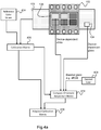
- Figure 4a shows a schematic representation of a method for obtaining an adapted calibration transformation 416.
- the following examples assume the transformations to be matrices, however matrices are not necessary and it will be known to the person skilled in the art that there are other ways of performing the transformations (e.g. look-up tables, TRC-matrix transformations).
- a first step is to perform the conventional color calibration.
- a calibration matrix 406 for example of size 3x3, is computed by minimizing the color difference between the transformed RGB colors 106 and the reference colorimetric values 404.
- a matrix-based calibration is typically adopted due to its superior perceptual quality in pathology slide images. However, the invention applies to any calibration transformation.
- the invention then applies a chromatic adaptation to the calibration transformation, e.g. calibration matrix 406.
- step 414 The determination of a chromatic adaptation matrix (or other function more generally) is shown as step 414.
- a scanner white point in the device-independent color space may be derived from this device-dependent white by applying the eventually adapted calibration matrix to the color target white patch 106.
- white point is generally used to refer to the representation of white in the device-independent color space, whereas the term “scanner white” refers the color of the white patch as represented in the scanner color space.
- Another input is the empty slide color 104 in the device-dependent color space (termed “Device-dependent glass” in Figure 4a ).
- Another input is the desired color 408 for the glass area in a target color space.
- Another input is the calibration matrix 406.
- the determination of the chromatic adaptation matrix is for example an iterative minimization process, explained in detail below.
- the resulting chromatic adaptation matrix is applied to the calibration matrix to derive the adapted calibration matrix 416.
- This adapted calibration matrix may then be used to transform from the device-dependent color space to the device-independent color space, with the empty glass area transformed to a color in the device-independent color space which corresponds to the desired color 408 in the target color space.
- the device-dependent color space is RGB
- the device-independent color space is XYZ
- the target color space is sRGB.
- Figure 4b shows the steps in determining the chromatic adaptation matrix and the resulting adapted calibration matrix in more detail. It shows the steps 414 and 416 of Figure 4a in more detail.
- the process in this example is an iterative process which is implemented as a minimization problem. It generates the chromatic adaptation matrix as a series of iterative adjustments, with the aim of minimizing a color difference in the target color space between the desired color 408 for the empty glass area and the actual empty glass color (in the target color space) as obtained by the adapted calibration matrix.
- the target color space may be the device-independent color space.
- the desired color is set in the XYZ color space.
- a desired color in the color-independent color space could be selected or even derived using an inverse transformation from a display color space.
- Figures 4a and 4b however show a preferred implementation in which the target color space is a color space used by an output device, to enable a more intuitive setting of the desired color.
- the XYZ device-independent color space is used in color transformations so is not visually intuitive.
- the chromatic adaptation method is performed in the device-independent color space rather than in the target color space. It makes use of a transformation between input and output white points in the device-independent color space. Thus, it may be considered to be a modification of the white point (i.e. in the device-independent color space).
- the native scanner white (“device-dependent white”) is converted to the scanner white point (shown as "Scanner white point XYZ”) in the device-independent color space in step 500 by using the calibration matrix 406.
- the calibration matrix is applied only once to the scanned color target.
- the process finds a transformation (e.g. matrix) which adapts the scanner white point.
- a corresponding transformation is then applied to the calibration matrix.
- this adapted scanner white point may be considered to be an optimal scanner white point in the device-independent color space, and it corresponds to a mapping from the device-dependent color space to the device-independent color space which results in the empty glass area having the desired color.
- the scanner white point is adapted to a new scanner white point in step 501 as a series of iterations.
- a next iteration of the resulting chromatic adaptation matrix is calculated in step 502. It is applied to the calibration matrix 406 to derive a next iteration of the adapted calibration matrix 503.
- a transformation 503 from the device-independent color space (XYZ) is then performed to derive the glass color in the target color space (sRGB in this example).
- a color difference with the desired color 408 in the same target color space is then performed in step 505 to give an error value.
- This color error is for example calculated using the known DeltaE or Eucledian methods for color differences between the RGB (or XYZ) co-ordinates.
- This error value is used to adjust the calculation of the chromatic adaptation matrix in a next iteration.
- the error value is provided for use in the next iteration. For this repeated iterative process, the method returns to step 501.
- steps 501 and 502 involves determining a chromatic adaptation matrix, given the white point in the device-independent color space as a source white point and an adapted scanner white point as a destination white point.
- the adapted white point set in step 501 will correspond with the optimal scanner white point, which is the scanner white point which results in the desired glass color in the target color space.
- the setting of the destination white point in step 501 for example may be implemented using the Nelder-Mead (downhill simplex) approach, which is a numerical method used in finding the minimum or maximum of an objective function.
- the method can repeat until it meets a predefined constraint(s) such as: maximum number of iterations, maximum number of function evaluations, and tolerance on the difference between two consecutive function values.
- the chromatic adaptation matrix is obtained such that the optimal scanner white point in the device-independent color space is reached, corresponding to the desired color of the glass area in the target color space.
- the final iteration of the adapted calibration matrix 416 is output.
- the error signal may be considered to correspond to the error from an optimal scanner white point, in that the iterations conclude when the adapted scanner white point is optimal.
- the adapted calibration matrix is computed based on the chromatic adaptation matrix transforming the native scanner white point of the scanner to an optimal scanner white point.
- the process optimizes how the native scanner white point is processed.
- the adapted calibration matrix 416 translates to the device-independent color space.
- the same adapted calibration matrix may be used for different output devices, i.e. different target color spaces.
- the obtained adapted calibration matrix may thus be applied to WSI images from a particular scanner with a particular slide format in order to achieve a desired glass area output color in a device-independent color space.
- a user may then apply a further transformation to map to their desired target color space.
- the obtained adapted calibration matrix may be combined with a further transformation to enable translation directly from the device-dependent (scanner) color space to the desired target (e.g. output device) color space.
- a Gamma transformation may be applied to the WSI in the output device, e.g. display, color space before the display displays the WSI.
- a transformation from the linear target space to a desired output color space such as sRGB may also be performed.
- the process of deriving the adapted calibration matrix is a calibration process which prepares one particular scanner type and slide type to be able to generate images with a known and desired output color of the empty glass area.
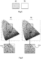
- Figure 5 shows an exaggerated illustration of the empty slide area 104 before and after being calibrated with an adapted calibration transformation 416.
- Figure 5a shows raw scanner acquisition of empty glass area 104.
- Figure 5b shows a scanner output of empty glass area 104 after calibration with an adapted calibration matrix 416.
- Figure 5 schematically shows the sRGB representation of an empty glass area 104 as a raw scanner image and after applying the adapted calibration matrix 416.
- Figure 5a for example schematically represents RGB co-ordinates [0.74, 0.74, 0.72] and
- Figure 5b represents mean RGB co-ordinates [0.85, 0.85, 0.85], which corresponds to a desired color 408 used in optimization. This simply represents an example of possible color change.
- Figure 6 shows the distribution of color target patches in a chromaticity diagram.
- Figure 6a shows raw patches after applying calibration matrix 406.
- Figure 6b shows raw patches after applying the adapted calibration matrix 416.
- a color target patch is given by a black dot with a label name.
- the triangle shown in white dotted lines represents the sRGB color space.
- Figure 6 shows the distribution of IT8 color target patches, in the chromaticity plot, acquired by a scanner after applying only the calibration matrix 406 in Figure 6a and after applying the adapted calibration matrix 416 in Figure 6b . It shows that there is a slight shift in the overall color distribution. For example the patch L18 602a appear to be on the upper corner of the sRGB triangle in Figure 6a , while the patch 602b is shifted slightly lower and to the right in Figure 6b . However, the coverage of the patches in the sRGB color space is comparable in both of the transformations. It shows that the chromatic adaption of the calibration matrix 406 does not limit the reproduction of colors in sRGB color space.
- Figure 7 shows an area of a whole slide image before and after calibrating.
- Figure 7a shows raw scanner acquisition of the WSI.
- Figure 7b shows the scanner output after applying the calibration matrix 406 to the WSI.
- Figure 7c shows the scanner output after applying the adapted calibration matrix 416 to the WSI.
- the empty slide area 104 appears to become a neutral white in Figure 7c and appears more natural and offers higher visual contrast when compared with Figure 7b.
- Figure 7 shows a cropped area of the WSI, where different shades of empty slide areas 104 can be seen in an un-calibrated raw image of Figure 7a and in the image calibrated using a calibration matrix 406 only in Figure 7b .
- the same raw image, calibrated using the adapted calibration matrix 416 in Figure 7c shows a neutral white background as specified by the desired color 408.
- the adapted calibration matrix for example enables a scanner with multiple cameras (e.g. high resolution and low resolution) to generate the same output colors (in particular background glass color) in the target color space.
- a low-resolution camera may for example be used in tissue detection and a high-resolution camera may be used in tissue scanning.
- a system in accordance with the invention for obtaining an adapted calibration transformation combines a scanner for obtaining a WSI in the device-dependent color space and a processor to perform the processing steps described above.
- each step of the flow charts of Figures 4a and 4b may represent a different action performed by a processor, and may be performed by a respective module of the processing processor.
- the processor can be implemented in numerous ways, with software and/or hardware, to perform the various functions required.
- the processor typically employs one or more microprocessors that may be programmed using software (e.g., microcode) to perform the required functions.
- the processor may be implemented as a combination of dedicated hardware to perform some functions and one or more programmed microprocessors and associated circuitry to perform other functions.
- circuitry examples include, but are not limited to, conventional microprocessors, application specific integrated circuits (ASICs), and field-programmable gate arrays (FPGAs).
- ASICs application specific integrated circuits
- FPGAs field-programmable gate arrays
- the processor may be associated with one or more storage media such as volatile and non-volatile computer memory such as RAM, PROM, EPROM, and EEPROM.
- the storage media may be encoded with one or more programs that, when executed on one or more processors and/or controllers, perform the required functions.
- Various storage media may be fixed within a processor or controller or may be transportable, such that the one or more programs stored thereon can be loaded into a processor.
- a single processor or other unit may fulfill the functions of several items recited in the claims.
- the mere fact that certain measures are recited in mutually different dependent claims does not indicate that a combination of these measures cannot be used to advantage.
- a computer program may be stored/distributed on a suitable medium, such as an optical storage medium or a solid-state medium supplied together with or as part of other hardware, but may also be distributed in other forms, such as via the Internet or other wired or wireless telecommunication systems.
- a suitable medium such as an optical storage medium or a solid-state medium supplied together with or as part of other hardware, but may also be distributed in other forms, such as via the Internet or other wired or wireless telecommunication systems.
Landscapes
- Engineering & Computer Science (AREA)
- Multimedia (AREA)
- Physics & Mathematics (AREA)
- Computer Vision & Pattern Recognition (AREA)
- General Physics & Mathematics (AREA)
- Signal Processing (AREA)
- Analytical Chemistry (AREA)
- Optics & Photonics (AREA)
- Theoretical Computer Science (AREA)
- Chemical & Material Sciences (AREA)
- Color Image Communication Systems (AREA)
- Image Processing (AREA)
- Facsimile Image Signal Circuits (AREA)
Priority Applications (5)
| Application Number | Priority Date | Filing Date | Title |
|---|---|---|---|
| EP19220155.6A EP3846431A1 (fr) | 2019-12-31 | 2019-12-31 | Procédé et système d'imagerie plein champ |
| US17/790,291 US12010467B2 (en) | 2019-12-31 | 2020-12-24 | Method and system for whole slide imaging |
| PCT/EP2020/087847 WO2021136740A1 (fr) | 2019-12-31 | 2020-12-24 | Procédé et système pour imagerie de lame entière |
| CN202080091147.XA CN114902644B (zh) | 2019-12-31 | 2020-12-24 | 用于全玻片成像的方法和系统 |
| DE112020006413.1T DE112020006413T5 (de) | 2019-12-31 | 2020-12-24 | Verfahren und system für gesamtobjektträger-bildgebung |
Applications Claiming Priority (1)
| Application Number | Priority Date | Filing Date | Title |
|---|---|---|---|
| EP19220155.6A EP3846431A1 (fr) | 2019-12-31 | 2019-12-31 | Procédé et système d'imagerie plein champ |
Publications (1)
| Publication Number | Publication Date |
|---|---|
| EP3846431A1 true EP3846431A1 (fr) | 2021-07-07 |
Family
ID=69061176
Family Applications (1)
| Application Number | Title | Priority Date | Filing Date |
|---|---|---|---|
| EP19220155.6A Withdrawn EP3846431A1 (fr) | 2019-12-31 | 2019-12-31 | Procédé et système d'imagerie plein champ |
Country Status (5)
| Country | Link |
|---|---|
| US (1) | US12010467B2 (fr) |
| EP (1) | EP3846431A1 (fr) |
| CN (1) | CN114902644B (fr) |
| DE (1) | DE112020006413T5 (fr) |
| WO (1) | WO2021136740A1 (fr) |
Citations (3)
| Publication number | Priority date | Publication date | Assignee | Title |
|---|---|---|---|---|
| US20040199346A1 (en) * | 2000-04-26 | 2004-10-07 | Microsoft Corporation | Method of achieving high color fidelty in a digital image capture device and a capture device incorporating same |
| WO2009039209A1 (fr) * | 2007-09-18 | 2009-03-26 | Canon Kabushiki Kaisha | Procédé de génération d'un profil colorimétriquement précis à large plage de luminance |
| US20150124072A1 (en) * | 2013-11-01 | 2015-05-07 | Datacolor, Inc. | System and method for color correction of a microscope image |
Family Cites Families (17)
| Publication number | Priority date | Publication date | Assignee | Title |
|---|---|---|---|---|
| JP3072729B2 (ja) | 1998-10-09 | 2000-08-07 | 日本電気株式会社 | カラーマッチング方法、カラーマッチング装置並びにプログラムを記録した機械読み取り可能な記録媒体 |
| DE60321159D1 (de) * | 2002-10-18 | 2008-07-03 | Hamamatsu Photonics Kk | Schiebeglas, abdeckglas und pathologisches diagnosesystem |
| DE10322378B4 (de) | 2003-05-17 | 2009-03-19 | Heidelberger Druckmaschinen Ag | Verfahren zur Farbtransformation mittels Farbprofilen |
| US8243325B2 (en) * | 2005-07-08 | 2012-08-14 | Xerox Corporation | Method for prepress-time color match verification and correction |
| US7684080B2 (en) | 2006-06-07 | 2010-03-23 | Adobe Systems Incorporated | Accommodating creative white point |
| EP2046067A4 (fr) * | 2006-07-25 | 2010-04-21 | Nikon Corp | Procédé de détermination de matrice de conversion, appareil de traitement d'images, programme de traitement d'images et appareil d'imagerie |
| CN102075666B (zh) | 2009-11-25 | 2018-09-18 | 惠普开发有限公司 | 用于从图像去除背景色彩的方法和装置 |
| US8797589B2 (en) * | 2010-08-19 | 2014-08-05 | Xerox Corporation | Color management and calibration using a scanner or camera |
| US20130044200A1 (en) * | 2011-08-17 | 2013-02-21 | Datacolor, Inc. | System and apparatus for the calibration and management of color in microscope slides |
| US9797767B2 (en) * | 2014-08-26 | 2017-10-24 | General Electric Company | Calibration of microscopy systems |
| US10746980B2 (en) * | 2014-08-26 | 2020-08-18 | General Electric Company | Calibration of microscopy systems |
| US9799305B2 (en) * | 2014-09-19 | 2017-10-24 | Barco N.V. | Perceptually optimised color calibration method and system |
| CN107197225B (zh) * | 2017-06-13 | 2019-04-05 | 浙江大学 | 基于色适应模型的彩色数码相机白平衡校正方法 |
| CN109218698B (zh) * | 2018-10-19 | 2020-01-21 | 浙江大学 | 一种高容错性的彩色数码相机颜色校正方法 |
| US11609574B2 (en) * | 2018-11-13 | 2023-03-21 | FLIR Belgium BVBA | Extrinsic sensor calibration systems and methods |
| CN111448476B (zh) * | 2019-03-08 | 2023-10-31 | 深圳市大疆创新科技有限公司 | 在无人飞行器与地面载具之间共享绘图数据的技术 |
| CN110517268A (zh) * | 2019-08-29 | 2019-11-29 | 中国科学院深圳先进技术研究院 | 病理图像处理方法、装置、图像分析系统及存储介质 |
-
2019
- 2019-12-31 EP EP19220155.6A patent/EP3846431A1/fr not_active Withdrawn
-
2020
- 2020-12-24 DE DE112020006413.1T patent/DE112020006413T5/de active Pending
- 2020-12-24 WO PCT/EP2020/087847 patent/WO2021136740A1/fr not_active Ceased
- 2020-12-24 US US17/790,291 patent/US12010467B2/en active Active
- 2020-12-24 CN CN202080091147.XA patent/CN114902644B/zh active Active
Patent Citations (3)
| Publication number | Priority date | Publication date | Assignee | Title |
|---|---|---|---|---|
| US20040199346A1 (en) * | 2000-04-26 | 2004-10-07 | Microsoft Corporation | Method of achieving high color fidelty in a digital image capture device and a capture device incorporating same |
| WO2009039209A1 (fr) * | 2007-09-18 | 2009-03-26 | Canon Kabushiki Kaisha | Procédé de génération d'un profil colorimétriquement précis à large plage de luminance |
| US20150124072A1 (en) * | 2013-11-01 | 2015-05-07 | Datacolor, Inc. | System and method for color correction of a microscope image |
Also Published As
| Publication number | Publication date |
|---|---|
| US12010467B2 (en) | 2024-06-11 |
| CN114902644B (zh) | 2025-06-17 |
| DE112020006413T5 (de) | 2022-12-08 |
| WO2021136740A1 (fr) | 2021-07-08 |
| US20230104460A1 (en) | 2023-04-06 |
| CN114902644A (zh) | 2022-08-12 |
Similar Documents
| Publication | Publication Date | Title |
|---|---|---|
| US6671067B1 (en) | Scanner and printer profiling system | |
| US5420979A (en) | Method and apparatus for using composite transforms to form intermediary image data metrics which achieve device/media compatibility for subsequent imaging applications | |
| US6421142B1 (en) | Out-of-gamut color mapping strategy | |
| US20020036696A1 (en) | Image processing method, image processing apparatus and recording medium storing program therefor | |
| US20010035989A1 (en) | Method, apparatus and recording medium for color correction | |
| US7333136B2 (en) | Image processing apparatus for carrying out tone conversion processing and color correction processing using a three-dimensional look-up table | |
| US7046400B2 (en) | Adjusting the color, brightness, and tone scale of rendered digital images | |
| JP2001189875A (ja) | 画像捕捉の非線形性を補償するためのプロファイルの構成 | |
| EP2056585A2 (fr) | Appareil de conversion d'image, support de stockage de programme de conversion d'image et système d'affichage d'images | |
| US7477294B2 (en) | Method for evaluating and correcting the image data of a camera system | |
| US6954227B2 (en) | Method, apparatus, and recording medium for image correction | |
| EP0631431A1 (fr) | Appareil de traitement d'image et procédé pour préparer les données représentant une image en couleur | |
| US12010467B2 (en) | Method and system for whole slide imaging | |
| JP2002033934A (ja) | 画像処理装置及び方法 | |
| US7733353B2 (en) | System and method for profiling digital-image input devices | |
| JP2001358960A (ja) | 色変換係数導出方法、色変換方法、記録媒体および色変換装置 | |
| KR101023508B1 (ko) | 복수의 광원을 포함하는 영상의 색상 보정 장치 및 방법 | |
| US8363267B2 (en) | Image forming apparatus and color converting method thereof | |
| JP4633806B2 (ja) | 色プロファイルのための色補正テクニック | |
| JP7659874B1 (ja) | 手術画像処理装置 | |
| JP4881325B2 (ja) | ディジタル画像入力装置のプロファイリング | |
| Kuznetsov | Color Management in Printing | |
| WO2025245280A1 (fr) | Utilisation de tables de consultation de couleurs pour générer des images de pathologie monoplex à partir d'images multiplex | |
| JP2000134485A (ja) | カラー印刷画像を製作するときのカラー原稿画像の画像情報の処理方法 | |
| JP2001346062A (ja) | 画像処理装置、画像処理方法、およびその方法をコンピュータに実行させるプログラムを記録したコンピュータ読み取り可能な記録媒体 |
Legal Events
| Date | Code | Title | Description |
|---|---|---|---|
| PUAI | Public reference made under article 153(3) epc to a published international application that has entered the european phase |
Free format text: ORIGINAL CODE: 0009012 |
|
| STAA | Information on the status of an ep patent application or granted ep patent |
Free format text: STATUS: THE APPLICATION HAS BEEN PUBLISHED |
|
| AK | Designated contracting states |
Kind code of ref document: A1 Designated state(s): AL AT BE BG CH CY CZ DE DK EE ES FI FR GB GR HR HU IE IS IT LI LT LU LV MC MK MT NL NO PL PT RO RS SE SI SK SM TR |
|
| STAA | Information on the status of an ep patent application or granted ep patent |
Free format text: STATUS: REQUEST FOR EXAMINATION WAS MADE |
|
| STAA | Information on the status of an ep patent application or granted ep patent |
Free format text: STATUS: THE APPLICATION HAS BEEN WITHDRAWN |
|
| 17P | Request for examination filed |
Effective date: 20220107 |
|
| RBV | Designated contracting states (corrected) |
Designated state(s): AL AT BE BG CH CY CZ DE DK EE ES FI FR GB GR HR HU IE IS IT LI LT LU LV MC MK MT NL NO PL PT RO RS SE SI SK SM TR |
|
| 18W | Application withdrawn |
Effective date: 20220114 |